EP4148231A1 - Bereitstellung von steuerinformationen - Google Patents
Bereitstellung von steuerinformationen Download PDFInfo
- Publication number
- EP4148231A1 EP4148231A1 EP21195601.6A EP21195601A EP4148231A1 EP 4148231 A1 EP4148231 A1 EP 4148231A1 EP 21195601 A EP21195601 A EP 21195601A EP 4148231 A1 EP4148231 A1 EP 4148231A1
- Authority
- EP
- European Patent Office
- Prior art keywords
- feed beam
- measurement unit
- inertial measurement
- reference position
- mining machine
- Prior art date
- Legal status (The legal status is an assumption and is not a legal conclusion. Google has not performed a legal analysis and makes no representation as to the accuracy of the status listed.)
- Granted
Links
Images


Classifications
-
- E—FIXED CONSTRUCTIONS
- E21—EARTH OR ROCK DRILLING; MINING
- E21C—MINING OR QUARRYING
- E21C35/00—Details of, or accessories for, machines for slitting or completely freeing the mineral from the seam, not provided for in groups E21C25/00 - E21C33/00, E21C37/00 or E21C39/00
- E21C35/06—Equipment for positioning the whole machine in relation to its sub-structure
-
- E—FIXED CONSTRUCTIONS
- E21—EARTH OR ROCK DRILLING; MINING
- E21B—EARTH OR ROCK DRILLING; OBTAINING OIL, GAS, WATER, SOLUBLE OR MELTABLE MATERIALS OR A SLURRY OF MINERALS FROM WELLS
- E21B7/00—Special methods or apparatus for drilling
- E21B7/02—Drilling rigs characterised by means for land transport with their own drive, e.g. skid mounting or wheel mounting
- E21B7/022—Control of the drilling operation; Hydraulic or pneumatic means for activation or operation
-
- E—FIXED CONSTRUCTIONS
- E21—EARTH OR ROCK DRILLING; MINING
- E21B—EARTH OR ROCK DRILLING; OBTAINING OIL, GAS, WATER, SOLUBLE OR MELTABLE MATERIALS OR A SLURRY OF MINERALS FROM WELLS
- E21B7/00—Special methods or apparatus for drilling
- E21B7/02—Drilling rigs characterised by means for land transport with their own drive, e.g. skid mounting or wheel mounting
- E21B7/025—Rock drills, i.e. jumbo drills
-
- E—FIXED CONSTRUCTIONS
- E21—EARTH OR ROCK DRILLING; MINING
- E21B—EARTH OR ROCK DRILLING; OBTAINING OIL, GAS, WATER, SOLUBLE OR MELTABLE MATERIALS OR A SLURRY OF MINERALS FROM WELLS
- E21B19/00—Handling rods, casings, tubes or the like outside the borehole, e.g. in the derrick; Apparatus for feeding the rods or cables
- E21B19/08—Apparatus for feeding the rods or cables; Apparatus for increasing or decreasing the pressure on the drilling tool; Apparatus for counterbalancing the weight of the rods
-
- E—FIXED CONSTRUCTIONS
- E21—EARTH OR ROCK DRILLING; MINING
- E21B—EARTH OR ROCK DRILLING; OBTAINING OIL, GAS, WATER, SOLUBLE OR MELTABLE MATERIALS OR A SLURRY OF MINERALS FROM WELLS
- E21B7/00—Special methods or apparatus for drilling
- E21B7/04—Directional drilling
- E21B7/046—Directional drilling horizontal drilling
Definitions
- the present application relates generally to providing control information. More specifically, the present application relates to providing joint control information.
- Mobile mining machines work in a challenging environment such as in an underground mine.
- Rock drilling is typically carried out by using drilling equipment comprising a carrier provided with at least one boom with a rock drilling unit at a distal end of the at least one boom.
- the rock drilling unit comprises a feeding system configured to keep a drill bit in contact with rock during drilling.
- the feeding system comprises a feed beam configured to support and guide a rock drilling device that is configured to move along the feed beam during a drilling procedure. As accurate control of the feed beam enables accurate rock drilling, controlling the position of the feed beam plays a role in efficient operation.
- an apparatus for controlling a mobile mining machine comprising means for performing: determining a reference position of a feed beam, the feed beam being connected to a boom of a mobile mining machine; receiving measurement information provided by an inertial measurement unit associated with the feed beam, estimating, based on the measurement information, movement of the inertial measurement unit, and providing, based on the reference position of the feed beam and the estimated movement of the at inertial measurement unit, joint control information for controlling a position of the feed beam.
- a method comprising: determining a reference position of a feed beam, the feed beam being connected to a boom of a mobile mining machine; receiving measurement information provided by an inertial measurement unit associated with the feed beam, estimating, based on the measurement information, movement of the inertial measurement unit, and providing, based on the reference position of the feed beam and the estimated movement of the at inertial measurement unit, joint control information for controlling a position of the feed beam.
- a computer program comprising instructions for causing an apparatus to perform at least the following: determining a reference position of a feed beam, the feed beam being connected to a boom of a mobile mining machine; receiving measurement information provided by an inertial measurement unit associated with the feed beam, estimating, based on the measurement information, movement of the inertial measurement unit, and providing, based on the reference position of the feed beam and the estimated movement of the at inertial measurement unit, joint control information for controlling a position of the feed beam.
- an apparatus comprising at least one processor and at least one memory including computer program code, the at least one memory and the computer program code configured to with the at least one processor, cause the apparatus at least to: determine a reference position of a feed beam, the feed beam being connected to a boom of a mobile mining machine, receive measurement information provided by an inertial measurement unit associated with the feed beam, estimate, based on the measurement information, movement of the inertial measurement unit, and provide, based on the reference position of the feed beam and the estimated movement of the inertial measurement unit, joint control information for controlling a position of the feed beam.
- a non-transitory computer readable medium comprising program instructions for causing an apparatus to perform at least the following: determining a reference position of a feed beam, the feed beam being connected to a boom of a mobile mining machine; receiving measurement information provided by an inertial measurement unit associated with the feed beam, estimating, based on the measurement information, movement of the inertial measurement unit, and providing, based on the reference position of the feed beam and the estimated movement of the at inertial measurement unit, joint control information for controlling a position of the feed beam.
- a computer readable medium comprising program instructions for causing an apparatus to perform at least the following: determining a reference position of a feed beam, the feed beam being connected to a boom of a mobile mining machine; receiving measurement information provided by an inertial measurement unit associated with the feed beam, estimating, based on the measurement information, movement of the inertial measurement unit, and providing, based on the reference position of the feed beam and the estimated movement of the at inertial measurement unit, joint control information for controlling a position of the feed beam.
- Example embodiments relate to controlling a position of a feed beam of a mobile mining machine.
- the mobile mining machine comprises at least one boom such as a drilling boom provided with a rock drilling unit at a distal end of the at least one boom.
- the rock drilling unit comprises a feeding system configured to keep a drill bit in contact with rock during drilling.
- the feeding system comprises a feed beam configured to support and guide a rock drilling device that is arranged to move along the feed beam during a drilling procedure.
- the position control of the feed beam is based on hydraulic or electronic control with joint sensors.
- the hydraulic control works only with specific boom kinematics and the electronic control needs sensors for at least all the rotation joints, thereby requiring rotational sensors and wiring for each joint axis.
- wiring and angle sensors are prone to damage, especially in an underground environment.
- the sensors need to be calibrated separately.
- An example embodiment relates to an apparatus configured to determine a reference position of a feed beam, the feed beam being connected to a boom via at least one joint of a mobile mining machine, receive measurement information provided by an inertial measurement unit associated with the feed beam, estimate, based on the measurement information, movement of the inertial measurement unit, and provide, based on the reference position of the feed beam and the estimated movement of the inertial measurement unit, joint control information for controlling a position of the feed beam.
- FIG. 1 is a block diagram depicting an apparatus 100 operating in accordance with an example embodiment of the invention.
- the apparatus 100 may be, for example, an electronic device such as a module comprised by an automation or control system, a chip or a chipset.
- the apparatus 100 comprises one or more control circuitry, such as at least one processor 110 and at least one memory 160, including one or more algorithms such as computer program instructions 120 wherein the at least one memory 160 and the computer program instructions are configured, with the at least one processor 110 to cause the apparatus to carry out any of example functionalities described below.
- the processor 110 is a control unit operatively connected to read from and write to the memory 160.
- the processor 110 may also be configured to receive control signals received via an input interface and/or the processor 110 may be configured to output control signals via an output interface.
- the processor 110 may be configured to convert the received control signals into appropriate commands for controlling functionalities of the apparatus.
- the at least one memory 160 stores computer program instructions 120 which when loaded into the processor 110 control the operation of the apparatus 100 as explained below.
- the apparatus 100 may comprise more than one memory 160 or different kinds of storage devices.
- Computer program instructions 120 for enabling implementations of example embodiments of the invention or a part of such computer program instructions may be loaded onto the apparatus 100 by the manufacturer of the apparatus 100, by a user of the apparatus 100, or by the apparatus 100 itself based on a download program, or the instructions can be pushed to the apparatus 100 by an external device.
- the computer program instructions may arrive at the apparatus 100 via an electromagnetic carrier signal or be copied from a physical entity such as a computer program product, a memory device or a record medium such as a USB stick, a Compact Disc (CD), a Compact Disc Read-Only Memory (CD-ROM), a Digital Versatile Disk (DVD) or a Blu-ray disk.
- FIG. 2 is a block diagram depicting an apparatus 200 in accordance with an example embodiment of the invention.
- the apparatus 200 may be an electronic device such as a module comprised by an automation system or a control system, a Personal Computer (PC), a laptop, a desktop, a wireless terminal, a communication terminal, a computing device or the like. In the examples below it is assumed that the apparatus 200 is a computing device.
- PC Personal Computer
- the apparatus 200 is illustrated as comprising the apparatus 100, a display 210 and a user interface 220 for interacting with the computing device 200.
- the display 210 may also be configured to act as a user interface.
- the display may be a touch screen display.
- the display 210 and/or the user interface 220 may be external to the apparatus 200, but in communication with it.
- the user interface may also comprise a manually operable control such as a button, a key, a touch pad, a joystick, a stylus, a pen, a roller, a rocker, a keypad, a keyboard or any suitable input mechanism for inputting and/or accessing information.
- a manually operable control such as a button, a key, a touch pad, a joystick, a stylus, a pen, a roller, a rocker, a keypad, a keyboard or any suitable input mechanism for inputting and/or accessing information.
- the apparatus 200 of the example of Fig. 2 may also be configured to establish radio communication with another device using, for example, a cellular network, a Bluetooth or WiFi connection or the like. Alternatively or in addition, the apparatus 200 may be configured to communicate with another device using a wired connection.
- the apparatus 200 comprises a module operatively connected to a mobile mining machine.
- the apparatus 200 may be implemented in a control system of a mobile mining machine or the apparatus 200 may be configured to communicate with a control system of a mobile mining machine via a wired or wireless connection.
- the mobile mining machine comprises a drilling rig.
- the mobile mining machine comprises a carrier and at least one boom.
- the mobile mining machine comprises at least one boom provided with a rock drilling unit at a distal end of the at least one boom.
- the rock drilling unit comprises a feeding system configured to keep a drill bit in contact with rock during drilling.
- the feeding system comprises a feed beam configured to move with respect to a feed cradle connected to the at least one boom via one or more rotatable joints.
- the feed beam is configured to support and guide a rock drilling device that is arranged to move along the feed beam during a drilling procedure.
- the feed beam may comprise a feed rail.
- the apparatus 200 is configured to monitor and control the position of the feed beam. Monitoring and controlling the position of the feed beam may be performed based on a reference position of the feed beam.
- a position of the feed beam comprises an orientation of the feed beam with respect to a reference position of the feed beam.
- a reference position of a feed beam may comprise a desired position of the feed beam.
- a reference position may comprise a predetermined reference position or the apparatus 200 may be configured to determine the reference position based on, for example, measurement data, sensor data, a simulation, a machine learning algorithm, operator input, one or more environmental factors, a procedure for setting a reference position such as a navigation procedure and/or the like.
- the apparatus 200 is configured to determine the reference position based on information provided by a magnetometer and/or a gyrocompass.
- the apparatus 200 may be configured to receive information provided by a magnetometer and/or a gyrocompass and determine the reference position based on the received information.
- the apparatus 200 is configured to determine a reference position based on a navigation procedure.
- the navigation procedure may comprise, for example, aligning the boom to a desired position.
- the apparatus 200 may be configured to determine the reference position based on a position of an aligned boom in response to receiving an indication that the position of the aligned boom is accepted by the operator.
- the apparatus 200 maybe configured to determine the reference position based on a position of an aligned boom in response to receiving an indication that the position of the aligned boom corresponds to a predetermined alignment.
- a predetermine alignment may be indicated with a laser beam, for example.
- the apparatus 200 is configured to determine a reference position of a feed beam, the feed beam being connected to a boom of a mobile mining machine.
- a reference position of the feed beam may comprise location information and/or orientation information.
- Location information may comprise an absolute location such as a location in coordinates of a coordinate system or a relative location such as a location with respect to a particular reference point.
- Orientation information may comprise an angular position with respect to a particular reference point.
- the reference position comprises an angle of the feed beam with respect to the mobile mining machine.
- An angle of the feed beam with respect to the mobile mining machine may comprise an angle of the feed beam with respect to a predetermined reference point associated with the mobile mining machine.
- the reference position comprises an angle of the feed beam with respect to gravity.
- An angle of the feed beam with respect to gravity may comprise and an angle of the feed beam with respect to a direction of gravity at a geographic location.
- a direction of gravity may be considered as substantially stable and predictable on earth at least within a limited geographic area and substantially the same during a period of time.
- an advantage of the reference position comprising an angle of the feed beam with respect to gravity is that gravity enables an accurate and repeatable positioning independent of the position of the mobile mining machine.
- the reference position comprises a drilling angle.
- a drilling angle may comprise an orientation of the feed beam with respect to the mobile mining machine during drilling or an orientation of the feed beam with respect to gravity.
- the drilling angle comprises at least one of the following: a vertical angle or a horizontal angle.
- a vertical angle comprises an angle between the feed beam and a horizontal plane and a horizontal angle comprises an angle between the feed beam and a vertical plane.
- the feed beam is mechanically connected to the boom.
- the feed beam may be connected to a boom directly, through different kinds of joints and/or a feed cradle.
- the apparatus 200 is configured to receive measurement information provided by an inertial measurement unit associated with the feed beam.
- Measurement information may comprise, for example, measurement data and/or metadata relating to the measurement data, and the apparatus 200 may be configured to receive the measurement information provided by the inertial measurement unit via a wireless or wired connection.
- an advantage of associating the inertial measurement unit with the feed beam is that, based on the measurement information provided by the inertial measurement unit, position and/or movement of the feed beam may be determined.
- An inertial measurement unit associated with a feed beam may comprise an inertial measurement unit installed in the feeding system.
- the inertial measurement unit is installed to a feed rail.
- the inertial measurement unit installed to a feed cradle.
- an advantage of installing the inertial measurement unit to the feed rail or the feed cradle is that the structure of the feeding system may protect the inertial measurement unit from falling rocks, for example, thereby making the inertial measurement unit less prone to damage.
- An inertial measurement unit is configured to detect linear acceleration and angular velocity using a plurality of inertial sensors such as one or more accelerometers and one or more gyroscopes.
- An inertial measurement unit may further comprise a magnetometer for detecting a compass heading.
- the inertial measurement unit comprises at least one accelerometer and at least one gyroscope. According to an example embodiment, the inertial measurement unit further comprises at least one magnetometer.
- the apparatus 200 is configured to determine a position of the inertial measurement unit based on the measurement information provided by the inertial measurement unit.
- a position of the inertial measurement unit may comprise, for example, a six degrees of freedom (6 DOF) position of the inertial measurement unit.
- the apparatus 200 is further configured to determine the position of the feed beam based on the position of the inertial measurement unit associated with the feed beam.
- the apparatus 200 may further be configured to determine or estimate movement of the inertial measurement unit based on a change of position of the inertial measurement unit.
- the apparatus 200 is configured to estimate, based on the measurement information, movement of the at least one inertial measurement unit.
- the apparatus 200 may be configured to estimate movement of the at least one inertial measurement unit by using one or more sensor fusion algorithms.
- a sensor fusion algorithm may be configured to combine data from a plurality of sensors such as one or more accelerometers, gyroscopes and/or magnetometers in order to estimate a position of an object.
- sensors such as one or more accelerometers, gyroscopes and/or magnetometers
- a sensor fusion algorithm may be used for estimating the orientation and movement of the feed beam.
- an advantage estimating the orientation and movement of a feed beam using an inertial measurement unit is that rotational joint sensors requiring a sensors and wiring for each joint axis may be replaced with a single inertial measurement unit. Further, as rotational joint sensors and wiring are prone to damage in an underground mining environment, placing the inertial measurement unit appropriately enables reducing the number of interruptions caused by damaged sensors and/or wiring. Further, as calibration of a plurality of separate sensors is not necessary, using an inertial measurement unit enables more efficient operation.
- the apparatus 200 is configured to determine, based on the reference position of the feed beam and the estimated movement of the inertial measurement unit, joint control information for controlling a position of the feed beam.
- Determining the joint control information may comprise, for example, determining the position of the feed beam based on the measurement information provided by the inertial measurement unit, comparing the position of the feed beam with the reference position of the feed beam, and determining a control signal for maintaining the position of the feed beam with respect to the mobile mining machine or with respect to gravity.
- the apparatus 200 is configured to provide, based on the reference position of the feed beam and the estimated movement of the inertial measurement unit, joint control information for controlling a position of the feed beam.
- an advantage of providing joint control information for controlling a position of the feed beam based on the reference position of the feed beam and the estimated movement of the inertial measurement unit is that the position of the feed beam may be substantially maintained while operating the mobile mining machine. For example, the position of the feed beam may be maintained while controlling the at least one boom.
- Joint control information may comprise at least one control signal for controlling at least one valve configured to control an orientation of the feed beam and/or a position offset of the feed beam with respect to a reference point of the feed beam.
- the at least one valve may comprise, for example, a valve configured to control an orientation of the feed beam.
- the joint control information comprises joint control signals for controlling an orientation of the feed beam and/or controlling a position offset of the feed beam.
- the apparatus 200 may be configured to provide the joint control information to a dedicated controller configured to control the at least one valve or the apparatus 200 may be configured to control the at least one valve directly.
- the apparatus 200 is configured to control at least one valve based on the joint control information. Controlling the at least one valve may comprise controlling the at least one valve directly or through a dedicated controller.
- the apparatus 200 may be configured to control the at least one valve continuously or when at least one predetermined criterion is fulfilled.
- the at least one predetermined criterion may relate to, for example, a particular control mode, a particular state of the mobile mining machine, and/or the like.
- the apparatus 200 may be configured to control the at least one valve, when the mobile mining machine is stationary, but the boom is moving, or when the mobile mining machine is in a control mode aiming is to keep the feed beam in a desired orientation when the boom is moving.
- the apparatus 200 is configured to control the at least one valve during boom movement.
- an advantage of controlling the at least one valve during boom movement is that the position of the feed beam with respect to the mobile mining machine may be maintained when an operator moves the boom. In this way, drilling accuracy may be maintained even when the boom is moved.
- the apparatus 200 may be configured to utilize information from other sources for providing joint control information for controlling a position of the feed beam.
- the information from other sources may comprise, for example, contextual information relating to the mobile mining machine.
- Contextual information may comprise, for example, information on the environment or information on a structure of the mobile mining machine.
- Information on environment may comprise, for example, a model of the working environment of the mobile mining device such as a mine model.
- Information on a structure of the mobile mining machine may comprise, for example, information on a current position of one or more other booms of a multi-boom mobile mining machine.
- the apparatus 200 is configured to adjust the joint control information based on contextual information relating to the mobile mining machine.
- an advantage of utilizing additional information for providing joint control information is that, for example, collision with a tunnel floor or ceiling, or with other booms may be avoided.
- the apparatus 200 is configured to monitor the position and/or movement of the feed beam. Monitoring the position and/or movement of the feed beam may comprise, for example, providing information relating to the position and/or movement of the feed beam to a display.
- the apparatus 200 may be configured to provide information on a display on the reference position of the feed beam, an estimated position of the feed beam, a difference between the reference position and the estimated position of the feed beam, or the like. Further, the apparatus 200 may be configured to provide information of the joint control information on a display.
- the apparatus 200 is configured to provide information on an estimated orientation and/or estimated position offset of the feed beam on a display.
- Monitoring may further comprise indicating when the position of the feed beam fulfills at least one criterion.
- the apparatus 200 may be configured to, for example, provide a notification for the operator in response to movement of the feed beam reaching a predetermined threshold value. For example, assuming the operator has set a threshold value of 70 cm between holes to be drilled, the apparatus 200 may be configured to notify the operator when the feed beam has moved 70 cm, thereby assisting the operator to perform hole drilling more efficiently.
- the apparatus 200 is configured to determine that movement of the feed beam has reached a threshold value.
- a threshold value may comprise an orientation of the feed beam or a distance moved by the feed beam.
- the apparatus 200 is configured to provide a notification on a display in response to determining that the movement of the feed beam has reached a threshold value.
- the apparatus 200 comprises means for performing features of the apparatus 200, wherein the means for performing comprises at least one processor 110, at least one memory 160 including computer code 120 configured to, with the at least one processor 110, cause the performance of the apparatus 200.
- the apparatus 200 comprises means for determining a reference position of a feed beam, the feed beam being connected to a boom via at least one joint of a mobile mining machine, means for receiving measurement information provided by an inertial measurement unit associated with the feed beam, means for estimating, based on the measurement information, movement of the inertial measurement unit, and means for providing, based on the reference position of the feed beam and the estimated movement of the inertial measurement unit, joint control information for controlling a position of the feed beam.
- the apparatus 200 may further comprise means for controlling at least one valve based on the joint control information, means for adjusting the joint control information based contextual information relating to the mobile mining machine and/or means for controlling the at least one valve during boom movement.
- the apparatus 200 may further comprise means for providing information on an estimated orientation and/or estimated position offset of the feed beam on a display.
- the apparatus 200 may further comprise means for determining that movement of the feed beam has reached a threshold value, and/or means for providing a notification on a display in response to determining that movement of the feed beam has reached a threshold value.
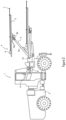
- Figure 3 illustrates an example drilling rig.
- the drilling rig comprises a rock drilling rig 1 comprising a carrier 2, one or more drilling booms 3 and drilling units 4 associated with the drilling booms 3.
- the boom may comprise two or more parts, objects, or portions 3a, 3b connected by a joint.
- the boom is further connected to a drilling unit 4 by a joint.
- the drilling unit 4 comprises a feed beam 5 on which a rock drilling device 6 can be moved by means of a feed device.
- the drilling unit 4 comprises a tool 7 with which impact pulses given by a percussion device of the rock drilling device 6 are transmitted to the rock to be drilled.
- an inertial measurement unit may be associated with the feed beam 5 by installing the inertial measurement unit to, for example, a feed rail or feed cradle 10a.
- the rock drilling rig 1 further comprises at least one control unit 8 arranged to control actuators of the rock drilling rig 1, for example.
- the control unit 8 may comprise, for example, the apparatus 200 comprising one or more processors executing computer program code stored in a memory, and it may comprise or be connected to a user interface with a display device 9 as well as operator input interface for receiving operator commands and information to the control unit 8.
- the control unit 8 is configured to control at least boom automation control related operations, and there may be one or more other control units in the rig for controlling other operations.
- one or more sensors 10 may be arranged for determining current position and direction of portions of the boom 3 and further the tool 7. Such sensors 10 may locate in connection with the boom 3, or alternatively the sensing may be executed remotely from the carrier or even elsewhere.
- the sensing data may be provided to the control unit 8 (or another control unit for positioning), which may execute appropriate computations.
- Figure 4 illustrates an example system 400 incorporating aspects of the previously disclosed embodiments.
- the apparatus 200 receives measurement information from an inertial measurement unit (IMU) 410.
- IMU inertial measurement unit
- an inertial measurement unit is configured to detect linear acceleration and angular velocity using a plurality of inertial sensors such as one or more accelerometers and one or more gyroscopes.
- An inertial measurement unit may further comprise a magnetometer for detecting a compass heading.
- the inertial measurement unit 410 comprises at least one three-dimensional (3D) accelerometer and at least one 3D gyroscope.
- the apparatus 200 is configured to determine a reference position of a feed beam, the feed beam being connected to a boom via at least one joint of a mobile mining machine, receive measurement information provided by an inertial measurement unit associated with the feed beam, estimate, based on the measurement information, movement of the inertial measurement unit, and provide, based on the reference position of the feed beam and the estimated movement of the inertial measurement unit, joint control information for controlling a position of the feed beam.
- valves 420 and 430 may comprise, for example, a valve configured to control an orientation of the feed beam.
- Figure 5 illustrates an example method 500 incorporating aspects of the previously disclosed embodiments. More specifically, the example method 500 illustrates providing control information. The method 500 may be performed by the apparatus 200.
- the method starts with determining 510 a reference position of a feed beam, the feed beam being connected to a boom of a mobile mining machine.
- a reference position of the feed beam may comprise location information and/or orientation information.
- Location information may comprise an absolute location such as a location in coordinates of a coordinate system or a relative location such as a location with respect to a particular reference point.
- Orientation information may comprise an angular position with respect to a particular reference point.
- the reference position comprises a drilling angle with respect to mobile mining machine.
- a drilling angle may comprise a vertical angle or a horizontal angle.
- An inertial measurement unit associated with a feed beam may comprise an inertial measurement unit installed in the feeding system such as an inertial measurement unit is installed to a feed rail or a feed cradle.
- the method further continues with estimating 530, based on the measurement information, movement of the inertial measurement unit. Movement of the inertial measurement unit may be estimated using, for example, one or more sensor fusion algorithms.
- the method further continues with providing 540, based on the reference position of the feed beam and the estimated movement of the inertial measurement unit, joint control information for controlling a position of the feed beam.
- Joint control information may comprise at least one control signal for controlling at least one valve configured to control an orientation of the feed beam and/or a position offset of the feed beam with respect to a reference point of the feed beam.
- the at least one valve may comprise, for example, a valve configured to control an orientation of the feed beam.
- an advantage of providing joint control information for controlling a position of a feed beam based on measurement information received from an inertial measurement unit associated with the feed beam is that a plurality of rotational joint sensors may be replaced with a single inertial measurement unit.
- the inertial measurement unit may be installed such that the structure of the mobile mining machine may protect the inertial measurement unit from external impacts.
- a technical effect of one or more of the example embodiments disclosed herein is that disruptions in controlling a position of the feed beam may be reduced as the inertial measurement unit is protected by the structure of the mobile mining machine.
- a further technical effect may be that the number of components needed for controlling position of the feed beam may be reduced.
- circuitry may refer to one or more or all of the following: (a) hardware-only circuit implementations (such as implementations in only analog and/or digital circuitry) and (b) combinations of hardware circuits and software, such as (as applicable): (i) a combination of analog and/or digital hardware circuit(s) with software/firmware and (ii) any portions of hardware processor(s) with software (including digital signal processor(s)), software, and memory(ies) that work together to cause an apparatus, such as a mobile phone or server, to perform various functions) and (c) hardware circuit(s) and or processor(s), such as a microprocessor(s) or a portion of a microprocessor(s), that requires software (e.g., firmware) for operation, but the software may not be present when it is not needed for operation.
- hardware-only circuit implementations such as implementations in only analog and/or digital circuitry
- combinations of hardware circuits and software such as (as applicable): (i) a combination of analog and/or digital hardware circuit(s
- circuitry also covers an implementation of merely a hardware circuit or processor (or multiple processors) or portion of a hardware circuit or processor and its (or their) accompanying software and/or firmware.
- circuitry also covers, for example and if applicable to the particular claim element, a baseband integrated circuit or processor integrated circuit for a mobile device or a similar integrated circuit in server, a cellular network device, or other computing or network device.
- Embodiments of the present invention may be implemented in software, hardware, application logic or a combination of software, hardware and application logic.
- the software, application logic and/or hardware may reside on the apparatus, a separate device or a plurality of devices. If desired, part of the software, application logic and/or hardware may reside on the apparatus, part of the software, application logic and/or hardware may reside on a separate device, and part of the software, application logic and/or hardware may reside on a plurality of devices.
- the application logic, software or an instruction set is maintained on any one of various conventional computer-readable media.
- a 'computer-readable medium' may be any media or means that can contain, store, communicate, propagate or transport the instructions for use by or in connection with an instruction execution system, apparatus, or device, such as a computer, with one example of a computer described and depicted in FIGURE 2 .
- a computer-readable medium may comprise a computer-readable storage medium that may be any media or means that can contain or store the instructions for use by or in connection with an instruction execution system, apparatus, or device, such as a computer.
- the different functions discussed herein may be performed in a different order and/or concurrently with each other. Furthermore, if desired, one or more of the above-described functions may be optional or may be combined.
Landscapes
- Engineering & Computer Science (AREA)
- Mining & Mineral Resources (AREA)
- Life Sciences & Earth Sciences (AREA)
- Geology (AREA)
- Geochemistry & Mineralogy (AREA)
- General Life Sciences & Earth Sciences (AREA)
- Environmental & Geological Engineering (AREA)
- Fluid Mechanics (AREA)
- Physics & Mathematics (AREA)
- Mechanical Engineering (AREA)
- Earth Drilling (AREA)
- Management, Administration, Business Operations System, And Electronic Commerce (AREA)
- Length Measuring Devices By Optical Means (AREA)
- Control And Safety Of Cranes (AREA)
- Drilling And Exploitation, And Mining Machines And Methods (AREA)
Priority Applications (8)
| Application Number | Priority Date | Filing Date | Title |
|---|---|---|---|
| EP21195601.6A EP4148231B1 (de) | 2021-09-08 | 2021-09-08 | Bereitstellung von steuerinformationen |
| US18/689,982 US20240384601A1 (en) | 2021-09-08 | 2022-09-07 | Providing control information |
| JP2024514387A JP2024535748A (ja) | 2021-09-08 | 2022-09-07 | 制御情報の提供 |
| AU2022341526A AU2022341526A1 (en) | 2021-09-08 | 2022-09-07 | Providing control information |
| CN202280060012.6A CN117916449A (zh) | 2021-09-08 | 2022-09-07 | 提供控制信息 |
| CA3229097A CA3229097A1 (en) | 2021-09-08 | 2022-09-07 | Providing control information |
| PCT/EP2022/074818 WO2023036802A1 (en) | 2021-09-08 | 2022-09-07 | Providing control information |
| CL2024000676A CL2024000676A1 (es) | 2021-09-08 | 2024-03-06 | Proporcionar información de control |
Applications Claiming Priority (1)
| Application Number | Priority Date | Filing Date | Title |
|---|---|---|---|
| EP21195601.6A EP4148231B1 (de) | 2021-09-08 | 2021-09-08 | Bereitstellung von steuerinformationen |
Publications (3)
| Publication Number | Publication Date |
|---|---|
| EP4148231A1 true EP4148231A1 (de) | 2023-03-15 |
| EP4148231B1 EP4148231B1 (de) | 2025-11-26 |
| EP4148231C0 EP4148231C0 (de) | 2025-11-26 |
Family
ID=77666415
Family Applications (1)
| Application Number | Title | Priority Date | Filing Date |
|---|---|---|---|
| EP21195601.6A Active EP4148231B1 (de) | 2021-09-08 | 2021-09-08 | Bereitstellung von steuerinformationen |
Country Status (8)
| Country | Link |
|---|---|
| US (1) | US20240384601A1 (de) |
| EP (1) | EP4148231B1 (de) |
| JP (1) | JP2024535748A (de) |
| CN (1) | CN117916449A (de) |
| AU (1) | AU2022341526A1 (de) |
| CA (1) | CA3229097A1 (de) |
| CL (1) | CL2024000676A1 (de) |
| WO (1) | WO2023036802A1 (de) |
Cited By (2)
| Publication number | Priority date | Publication date | Assignee | Title |
|---|---|---|---|---|
| EP4549694A1 (de) * | 2023-10-31 | 2025-05-07 | Sandvik Mining and Construction Oy | Verbesserung der bohrgenauigkeit für ein mobiles unterirdisches bohrgestell und zugehörige vorrichtungen, verfahren und computerprogramme |
| EP4571040A1 (de) * | 2023-12-11 | 2025-06-18 | Sandvik Mining and Construction Oy | Steuerung einer abbaumaschine |
Families Citing this family (1)
| Publication number | Priority date | Publication date | Assignee | Title |
|---|---|---|---|---|
| CN119664236B (zh) * | 2024-12-18 | 2025-07-01 | 中国华冶科工集团有限公司 | 伞钻设备的钻孔方法、装置、工控机及四臂伞钻 |
Citations (6)
| Publication number | Priority date | Publication date | Assignee | Title |
|---|---|---|---|---|
| WO2015120905A1 (en) * | 2014-02-14 | 2015-08-20 | Sandvik Mining And Construction Oy | Arrangement for initiating a remote operation mode |
| US9500079B2 (en) * | 2013-05-27 | 2016-11-22 | Sandvik Mining & Construction Oy | Method and control system for a mining vehicle and a mining vehicle |
| US20200049004A1 (en) * | 2018-08-07 | 2020-02-13 | Caterpillar Global Mining Europe Gmbh | Shearing system for longwall mining |
| WO2020187947A1 (en) * | 2019-03-19 | 2020-09-24 | Sandvik Mining And Construction Oy | Mine vehicle boom positioning control |
| AU2020286327A1 (en) * | 2019-12-18 | 2021-07-08 | Mining Tag S.A. | System for estimating distance, inclination and drilling speed of a mining machine and method to improve the drilling process of mining tunnels |
| US20210222498A1 (en) * | 2020-01-16 | 2021-07-22 | Caterpillar Global Mining Equipment Llc | System and method to automatically position a machine in an operating configuration |
Family Cites Families (2)
| Publication number | Priority date | Publication date | Assignee | Title |
|---|---|---|---|---|
| US20140172246A1 (en) * | 2012-12-14 | 2014-06-19 | Caterpillar Inc. | Automatic Swing and Radius Control System and Method for a Machine Implement |
| WO2014206471A1 (en) * | 2013-06-27 | 2014-12-31 | Sandvik Mining And Construction Oy | Arrangement for controlling percussive drilling process |
-
2021
- 2021-09-08 EP EP21195601.6A patent/EP4148231B1/de active Active
-
2022
- 2022-09-07 JP JP2024514387A patent/JP2024535748A/ja active Pending
- 2022-09-07 US US18/689,982 patent/US20240384601A1/en active Pending
- 2022-09-07 CA CA3229097A patent/CA3229097A1/en active Pending
- 2022-09-07 CN CN202280060012.6A patent/CN117916449A/zh active Pending
- 2022-09-07 WO PCT/EP2022/074818 patent/WO2023036802A1/en not_active Ceased
- 2022-09-07 AU AU2022341526A patent/AU2022341526A1/en active Pending
-
2024
- 2024-03-06 CL CL2024000676A patent/CL2024000676A1/es unknown
Patent Citations (6)
| Publication number | Priority date | Publication date | Assignee | Title |
|---|---|---|---|---|
| US9500079B2 (en) * | 2013-05-27 | 2016-11-22 | Sandvik Mining & Construction Oy | Method and control system for a mining vehicle and a mining vehicle |
| WO2015120905A1 (en) * | 2014-02-14 | 2015-08-20 | Sandvik Mining And Construction Oy | Arrangement for initiating a remote operation mode |
| US20200049004A1 (en) * | 2018-08-07 | 2020-02-13 | Caterpillar Global Mining Europe Gmbh | Shearing system for longwall mining |
| WO2020187947A1 (en) * | 2019-03-19 | 2020-09-24 | Sandvik Mining And Construction Oy | Mine vehicle boom positioning control |
| AU2020286327A1 (en) * | 2019-12-18 | 2021-07-08 | Mining Tag S.A. | System for estimating distance, inclination and drilling speed of a mining machine and method to improve the drilling process of mining tunnels |
| US20210222498A1 (en) * | 2020-01-16 | 2021-07-22 | Caterpillar Global Mining Equipment Llc | System and method to automatically position a machine in an operating configuration |
Cited By (4)
| Publication number | Priority date | Publication date | Assignee | Title |
|---|---|---|---|---|
| EP4549694A1 (de) * | 2023-10-31 | 2025-05-07 | Sandvik Mining and Construction Oy | Verbesserung der bohrgenauigkeit für ein mobiles unterirdisches bohrgestell und zugehörige vorrichtungen, verfahren und computerprogramme |
| WO2025093716A1 (en) * | 2023-10-31 | 2025-05-08 | Sandvik Mining And Construction Oy | Enhancing drilling accuracy for a mobile underground drilling rig, and related devices, methods and computer programs |
| EP4571040A1 (de) * | 2023-12-11 | 2025-06-18 | Sandvik Mining and Construction Oy | Steuerung einer abbaumaschine |
| WO2025125341A1 (en) * | 2023-12-11 | 2025-06-19 | Sandvik Mining And Construction Oy | Controlling of a mining machine |
Also Published As
| Publication number | Publication date |
|---|---|
| CA3229097A1 (en) | 2023-03-16 |
| US20240384601A1 (en) | 2024-11-21 |
| CL2024000676A1 (es) | 2024-12-20 |
| EP4148231B1 (de) | 2025-11-26 |
| AU2022341526A1 (en) | 2024-03-28 |
| WO2023036802A1 (en) | 2023-03-16 |
| CN117916449A (zh) | 2024-04-19 |
| JP2024535748A (ja) | 2024-10-02 |
| EP4148231C0 (de) | 2025-11-26 |
Similar Documents
| Publication | Publication Date | Title |
|---|---|---|
| US20240384601A1 (en) | Providing control information | |
| US7650252B2 (en) | Inclinometer measurement system and method providing correction for movement induced acceleration errors | |
| US11566470B2 (en) | Apparatus and method for positioning rock drilling rig | |
| JP2020530077A (ja) | 単一の位置センサを用いる回転プラットフォームのヨーおよび回転中心の決定方法 | |
| CN112854355B (zh) | 用于确定机械的位置和方向的方法 | |
| EP2817473B1 (de) | Vorrichtung zum ausrichten von bohrmaschinen | |
| US20200306909A1 (en) | Orientation apparatus for drilling machinery and method for orienting a drilling element of drilling machinery | |
| JP2002188389A (ja) | トンネルの発破掘削穿孔方法及びその穿孔システム | |
| EP3910159B1 (de) | Aktivierung eines referenzpunktes | |
| CN119062320A (zh) | 一种随钻姿态测量方法、系统、存储介质和电子设备 | |
| CA3174261C (en) | Activating a reference point | |
| US12197220B2 (en) | Selecting a route | |
| JPWO2023036802A5 (de) | ||
| CA3174324C (en) | Selecting a route | |
| EP4556677A1 (de) | Navigationskorrektur für bohrgestell | |
| CN119256145A (zh) | 提供控制信息 | |
| JP2025002385A (ja) | 掘削位置特定システムおよび掘削方法 | |
| CN121666563A (zh) | 控制履带式车辆的移动 | |
| Jones | Finesse in tough environments |
Legal Events
| Date | Code | Title | Description |
|---|---|---|---|
| PUAI | Public reference made under article 153(3) epc to a published international application that has entered the european phase |
Free format text: ORIGINAL CODE: 0009012 |
|
| STAA | Information on the status of an ep patent application or granted ep patent |
Free format text: STATUS: THE APPLICATION HAS BEEN PUBLISHED |
|
| AK | Designated contracting states |
Kind code of ref document: A1 Designated state(s): AL AT BE BG CH CY CZ DE DK EE ES FI FR GB GR HR HU IE IS IT LI LT LU LV MC MK MT NL NO PL PT RO RS SE SI SK SM TR |
|
| P01 | Opt-out of the competence of the unified patent court (upc) registered |
Effective date: 20230603 |
|
| STAA | Information on the status of an ep patent application or granted ep patent |
Free format text: STATUS: REQUEST FOR EXAMINATION WAS MADE |
|
| 17P | Request for examination filed |
Effective date: 20230915 |
|
| RBV | Designated contracting states (corrected) |
Designated state(s): AL AT BE BG CH CY CZ DE DK EE ES FI FR GB GR HR HU IE IS IT LI LT LU LV MC MK MT NL NO PL PT RO RS SE SI SK SM TR |
|
| GRAP | Despatch of communication of intention to grant a patent |
Free format text: ORIGINAL CODE: EPIDOSNIGR1 |
|
| STAA | Information on the status of an ep patent application or granted ep patent |
Free format text: STATUS: GRANT OF PATENT IS INTENDED |
|
| INTG | Intention to grant announced |
Effective date: 20250704 |
|
| GRAS | Grant fee paid |
Free format text: ORIGINAL CODE: EPIDOSNIGR3 |
|
| GRAA | (expected) grant |
Free format text: ORIGINAL CODE: 0009210 |
|
| STAA | Information on the status of an ep patent application or granted ep patent |
Free format text: STATUS: THE PATENT HAS BEEN GRANTED |
|
| AK | Designated contracting states |
Kind code of ref document: B1 Designated state(s): AL AT BE BG CH CY CZ DE DK EE ES FI FR GB GR HR HU IE IS IT LI LT LU LV MC MK MT NL NO PL PT RO RS SE SI SK SM TR |
|
| REG | Reference to a national code |
Ref country code: CH Ref legal event code: F10 Free format text: ST27 STATUS EVENT CODE: U-0-0-F10-F00 (AS PROVIDED BY THE NATIONAL OFFICE) Effective date: 20251126 Ref country code: GB Ref legal event code: FG4D |
|
| REG | Reference to a national code |
Ref country code: IE Ref legal event code: FG4D |
|
| REG | Reference to a national code |
Ref country code: DE Ref legal event code: R096 Ref document number: 602021042945 Country of ref document: DE |
|
| U01 | Request for unitary effect filed |
Effective date: 20251126 |
|
| U07 | Unitary effect registered |
Designated state(s): AT BE BG DE DK EE FI FR IT LT LU LV MT NL PT RO SE SI Effective date: 20251203 |