EP4148236A1 - Dispositif de réglage pour aubes à calage variable d'une turbomachine - Google Patents
Dispositif de réglage pour aubes à calage variable d'une turbomachine Download PDFInfo
- Publication number
- EP4148236A1 EP4148236A1 EP22192081.2A EP22192081A EP4148236A1 EP 4148236 A1 EP4148236 A1 EP 4148236A1 EP 22192081 A EP22192081 A EP 22192081A EP 4148236 A1 EP4148236 A1 EP 4148236A1
- Authority
- EP
- European Patent Office
- Prior art keywords
- lever
- adjusting
- ring
- coupling
- rod
- Prior art date
- Legal status (The legal status is an assumption and is not a legal conclusion. Google has not performed a legal analysis and makes no representation as to the accuracy of the status listed.)
- Pending
Links
- 230000008878 coupling Effects 0.000 claims abstract description 62
- 238000010168 coupling process Methods 0.000 claims abstract description 62
- 238000005859 coupling reaction Methods 0.000 claims abstract description 62
- 230000005540 biological transmission Effects 0.000 description 8
- 239000007789 gas Substances 0.000 description 8
- 238000002485 combustion reaction Methods 0.000 description 5
- 239000003350 kerosene Substances 0.000 description 2
- 238000000034 method Methods 0.000 description 2
- 239000000567 combustion gas Substances 0.000 description 1
- 230000001419 dependent effect Effects 0.000 description 1
- 239000000203 mixture Substances 0.000 description 1
- 239000000725 suspension Substances 0.000 description 1
- 238000011144 upstream manufacturing Methods 0.000 description 1
Images


Classifications
-
- F—MECHANICAL ENGINEERING; LIGHTING; HEATING; WEAPONS; BLASTING
- F01—MACHINES OR ENGINES IN GENERAL; ENGINE PLANTS IN GENERAL; STEAM ENGINES
- F01D—NON-POSITIVE DISPLACEMENT MACHINES OR ENGINES, e.g. STEAM TURBINES
- F01D17/00—Regulating or controlling by varying flow
- F01D17/10—Final actuators
- F01D17/12—Final actuators arranged in stator parts
- F01D17/14—Final actuators arranged in stator parts varying effective cross-sectional area of nozzles or guide conduits
- F01D17/16—Final actuators arranged in stator parts varying effective cross-sectional area of nozzles or guide conduits by means of nozzle vanes
- F01D17/162—Final actuators arranged in stator parts varying effective cross-sectional area of nozzles or guide conduits by means of nozzle vanes for axial flow, i.e. the vanes turning around axes which are essentially perpendicular to the rotor centre line
-
- F—MECHANICAL ENGINEERING; LIGHTING; HEATING; WEAPONS; BLASTING
- F01—MACHINES OR ENGINES IN GENERAL; ENGINE PLANTS IN GENERAL; STEAM ENGINES
- F01D—NON-POSITIVE DISPLACEMENT MACHINES OR ENGINES, e.g. STEAM TURBINES
- F01D7/00—Rotors with blades adjustable in operation; Control thereof
-
- F—MECHANICAL ENGINEERING; LIGHTING; HEATING; WEAPONS; BLASTING
- F01—MACHINES OR ENGINES IN GENERAL; ENGINE PLANTS IN GENERAL; STEAM ENGINES
- F01D—NON-POSITIVE DISPLACEMENT MACHINES OR ENGINES, e.g. STEAM TURBINES
- F01D17/00—Regulating or controlling by varying flow
- F01D17/20—Devices dealing with sensing elements or final actuators or transmitting means between them, e.g. power-assisted
-
- F—MECHANICAL ENGINEERING; LIGHTING; HEATING; WEAPONS; BLASTING
- F01—MACHINES OR ENGINES IN GENERAL; ENGINE PLANTS IN GENERAL; STEAM ENGINES
- F01D—NON-POSITIVE DISPLACEMENT MACHINES OR ENGINES, e.g. STEAM TURBINES
- F01D9/00—Stators
- F01D9/02—Nozzles; Nozzle boxes; Stator blades; Guide conduits, e.g. individual nozzles
- F01D9/04—Nozzles; Nozzle boxes; Stator blades; Guide conduits, e.g. individual nozzles forming ring or sector
- F01D9/041—Nozzles; Nozzle boxes; Stator blades; Guide conduits, e.g. individual nozzles forming ring or sector using blades
-
- F—MECHANICAL ENGINEERING; LIGHTING; HEATING; WEAPONS; BLASTING
- F02—COMBUSTION ENGINES; HOT-GAS OR COMBUSTION-PRODUCT ENGINE PLANTS
- F02C—GAS-TURBINE PLANTS; AIR INTAKES FOR JET-PROPULSION PLANTS; CONTROLLING FUEL SUPPLY IN AIR-BREATHING JET-PROPULSION PLANTS
- F02C9/00—Controlling gas-turbine plants; Controlling fuel supply in air- breathing jet-propulsion plants
- F02C9/16—Control of working fluid flow
- F02C9/20—Control of working fluid flow by throttling; by adjusting vanes
-
- F—MECHANICAL ENGINEERING; LIGHTING; HEATING; WEAPONS; BLASTING
- F04—POSITIVE - DISPLACEMENT MACHINES FOR LIQUIDS; PUMPS FOR LIQUIDS OR ELASTIC FLUIDS
- F04D—NON-POSITIVE-DISPLACEMENT PUMPS
- F04D29/00—Details, component parts, or accessories
- F04D29/40—Casings; Connections of working fluid
- F04D29/52—Casings; Connections of working fluid for axial pumps
- F04D29/54—Fluid-guiding means, e.g. diffusers
- F04D29/56—Fluid-guiding means, e.g. diffusers adjustable
- F04D29/563—Fluid-guiding means, e.g. diffusers adjustable specially adapted for elastic fluid pumps
-
- F—MECHANICAL ENGINEERING; LIGHTING; HEATING; WEAPONS; BLASTING
- F05—INDEXING SCHEMES RELATING TO ENGINES OR PUMPS IN VARIOUS SUBCLASSES OF CLASSES F01-F04
- F05D—INDEXING SCHEME FOR ASPECTS RELATING TO NON-POSITIVE-DISPLACEMENT MACHINES OR ENGINES, GAS-TURBINES OR JET-PROPULSION PLANTS
- F05D2220/00—Application
- F05D2220/30—Application in turbines
- F05D2220/32—Application in turbines in gas turbines
- F05D2220/323—Application in turbines in gas turbines for aircraft propulsion, e.g. jet engines
-
- F—MECHANICAL ENGINEERING; LIGHTING; HEATING; WEAPONS; BLASTING
- F05—INDEXING SCHEMES RELATING TO ENGINES OR PUMPS IN VARIOUS SUBCLASSES OF CLASSES F01-F04
- F05D—INDEXING SCHEME FOR ASPECTS RELATING TO NON-POSITIVE-DISPLACEMENT MACHINES OR ENGINES, GAS-TURBINES OR JET-PROPULSION PLANTS
- F05D2250/00—Geometry
- F05D2250/90—Variable geometry
-
- F—MECHANICAL ENGINEERING; LIGHTING; HEATING; WEAPONS; BLASTING
- F05—INDEXING SCHEMES RELATING TO ENGINES OR PUMPS IN VARIOUS SUBCLASSES OF CLASSES F01-F04
- F05D—INDEXING SCHEME FOR ASPECTS RELATING TO NON-POSITIVE-DISPLACEMENT MACHINES OR ENGINES, GAS-TURBINES OR JET-PROPULSION PLANTS
- F05D2260/00—Function
- F05D2260/50—Kinematic linkage, i.e. transmission of position
- F05D2260/56—Kinematic linkage, i.e. transmission of position using cams or eccentrics
-
- F—MECHANICAL ENGINEERING; LIGHTING; HEATING; WEAPONS; BLASTING
- F05—INDEXING SCHEMES RELATING TO ENGINES OR PUMPS IN VARIOUS SUBCLASSES OF CLASSES F01-F04
- F05D—INDEXING SCHEME FOR ASPECTS RELATING TO NON-POSITIVE-DISPLACEMENT MACHINES OR ENGINES, GAS-TURBINES OR JET-PROPULSION PLANTS
- F05D2270/00—Control
- F05D2270/60—Control system actuates means
- F05D2270/66—Mechanical actuators
Definitions
- the present invention relates to an adjustment arrangement for adjusting adjustable vanes of a turbomachine.
- the turbomachine can, for example, be a jet engine, e.g. B. a turbofan engine. Functionally, the turbomachine is divided into compressor, combustion chamber and turbine. In the case of the jet engine, for example, the air drawn in is compressed by the compressor and burned in the downstream combustion chamber with added kerosene. The resulting hot gas, a mixture of combustion gas and air, flows through the downstream turbine and is expanded in the process.
- Both the compressor and the turbine are usually made up of several stages, each with a stator (vane ring) and a rotor (rotor blade ring).
- Blade rings with adjustable blades are used in compressors and turbines of turbomachines.
- An adjustment arrangement for adjusting the blades can include an adjustment ring, which can be rotated about a ring axis or longitudinal axis of the turbomachine, with this rotary movement then being coupled to the individual blades of the blade ring, e.g transfer the respective adjustable vane.
- the present application focuses on the upstream mechanism, namely the gear for adjusting the adjusting ring. This allows the adjustment ring to be moved in the direction of rotation, i.e. rotated a little around its ring axis.
- the present invention is based on the technical problem of specifying an advantageous adjustment arrangement for adjustable vanes of a turbomachine.
- this is achieved with the adjustment arrangement according to claim 1 .
- this has a lever and a connecting rod which couples the lever to the adjusting ring.
- a coupling rod is provided, which is used for coupling to one or more other blade rings with adjustable blades, ie can create a simultaneous adjustment across the individual stages.
- the coupling rod couples to a power arm of the lever, which is rotatably mounted at a pivot point, with its load arm being coupled to the connecting rod and thus to the adjusting ring.
- An offset, in particular an axial offset, of the coupling rod is converted via the lever into an at least partial circumferential offset of the push rod and thus a rotation of the adjusting ring.
- the coupling rod and the push rod are arranged on different sides of the lever, so that the coupling rod and the push rod do not intersect, for example when viewed radially.
- this can allow for an essentially planar arrangement of the gearing that is tangential to the adjusting ring, which can be advantageous, for example, with regard to the introduction of force and accuracy and, for example, can also reduce joint wear.
- first coupling point of the connecting rod in which it couples to the adjusting ring
- second coupling point in which the connecting rod is coupled to the lever
- these two points are on the same viewed in the radial direction, since the two rods do not cross arranged side of the coupling rod.
- the "on opposite sides of the lever" arrangement may be such that the connecting rod is located at one end of the lever and the push rod at the opposite end of the lever extends away from the lever and the connecting rod.
- the terms “axial”, “radial” and “circumferential” and the associated directions relate to the ring axis, about which the adjusting ring can be adjusted with the gear, i.e. rotated.
- This ring axis typically coincides with a longitudinal axis of the module or of the turbomachine, about which, for example, its rotor blade rings rotate during operation.
- the adjustable blades are distributed circumferentially, and several adjustable blade rings can follow one another in an axially offset manner. With the adjustment, the angle of attack of the adjustable vanes can be changed, for example as a function of the operating state of the turbomachine.
- the connecting rod is tilted by a maximum of 10° with respect to a plane spanned by the lever. Further upper limits can, for example, be at most 8°, 6°, 4° or 2°.
- the tilting of the push rod relative to the plane is preferably within a corresponding interval, also taking into account any angular deflection that may result as a result of the adjustment.
- the tilting can also be at 0° (the push rod is in the plane), at least in a zero position of the adjusting ring.
- the level spanned by the lever can contain, for example, its pivot point and the coupling points to the connecting rod and the coupling rod.
- For the tilting of the connecting rod relative to this plane is then, for example, based on a connecting straight line placed in the connecting rod, which connects its coupling points (to the adjusting ring and to the lever) with one another.
- the push rod itself can also have a curved course, but it preferably extends in a straight line.
- the coupling rod lies in a plane spanned by the lever; reference is made to the above paragraphs with regard to the definition of the plane, which is preferably combined with the essentially non-tilted push rod.
- the coupling rod lies in a plane spanned by the lever; reference is made to the above paragraphs with regard to the definition of the plane, which is preferably combined with the essentially non-tilted push rod.
- an overall straight structure can be achieved (reduced wear and increased accuracy).
- This also makes it possible, for example, to reduce an oblique load on the push or coupling rod, which could otherwise lead to a higher weight of the rod(s) or also the lever in the structural-mechanical design.
- the transmission can preferably have further levers and push rods, which are assigned to different blade rings or stages in an axially offset manner on the coupling rod.
- these levers can lie in a common plane (that is, their coupling and pivot points lie in the same plane).
- the coupling rod for connecting the rims or steps has an at least partially axial extension, preferably it is parallel to the axial direction.
- said plane, which contains the coupling rod and the lever or levers, is parallel to the axis.
- the lever or levers can, for example, also be formed with a kink or a curve, with the two coupling points and the pivot point nevertheless spanning a plane.
- the lever is an overall planar component, which more preferably also applies to the levers of the other rings or steps.
- the push rod is essentially parallel to a tangent to the adjusting ring.
- This tangent is in a first Coupling point, in which the push rod is coupled to the adjusting ring, placed on the adjusting ring.
- the push rod that is "substantially parallel" to the tangent can be tilted, for example, by a maximum of 10°, 8°, 6° or 4° relative to the tangent.
- the push rod is preferably located at a corresponding interval over the adjustment path, ie also taking into account any angular offset as a result of the adjustment. In any case, in a zero position of the adjusting ring, the angle can also be 0°.
- the first coupling point is radially spaced at most 3 cm from the adjusting ring.
- this suspension point can also be arranged, for example, on a pin protruding radially outwards on the adjusting ring and accordingly be offset a little radially outwards.
- the first coupling point is preferably as close as possible to the ring, for example offset radially outwards by a maximum of 2.5 cm, 2 cm, 1.5 cm, 1 cm or 0.5 cm in the order in which they are named, which means, for example Allow additional deformation moments to be reduced on the ring.
- At least one of the coupling points of the connecting rod is formed by a ball joint, ie the first coupling point (to the adjusting ring) and/or the second coupling point (to the lever).
- a ball joint ie the first coupling point (to the adjusting ring) and/or the second coupling point (to the lever).
- the adjustment arrangement can preferably have an actuator, in particular a linear actuator, in addition to the gear mechanism.
- This can be arranged in such a way that its adjustment path has an axial component, preferably lies parallel to the axis.
- the actuator can then preferably be coupled to one of the levers assigned to the different rings or steps, in which case the adjustment can then be transferred from this lever to the other levers with the coupling rod.
- the actuator is arranged in a preferred embodiment in such a way that, viewed in the axial direction, it is on a straight line with the lever and the connecting rod lies. This straight line is preferably tangential to the adjusting ring, compare the comments above.
- adjustment rings are provided, which are associated with axially offset blade rings (in each case for adjusting the respective adjustment blades).
- a second adjustment ring which is connected to the coupling rod via a second push rod and a second lever in such a way that the second lever converts an offset of the coupling rod, in particular an axial offset, into an offset of the second push rod, in particular a circumferential offset.
- the axially consecutive levers differ in their load arms and/or their force arms, preferably both.
- the load arm can, for example, determine how far the respective push rod and thus the respective adjusting ring is offset, with this offset being able to decrease in an adjustable compressor, for example, from axially front to axially rear.
- the power arm can be used to measure the force with which the adjustment is made and thus the torque that is applied.
- the invention also relates to a module of a turbomachine, in particular a compressor module.
- the module has a plurality of rotor blade rings, each of which is equipped with adjustable blades, which can in particular be adjustable guide blade rings.
- An adjusting ring is assigned to each adjustable vane ring, these adjusting rings being connected to one another via the transmission described here.
- the individual adjustable vanes can then preferably each be coupled to the respective adjustment ring with an adjusting lever, so that its rotational offset rotates the adjustable vanes via the lever, ie changes their angle of attack.
- the invention also relates to a turbomachine with an adjustment arrangement disclosed here or a module just mentioned, preferably an aircraft engine, particularly preferably a turbofan engine. Furthermore, the invention relates the use of an adjustment arrangement described here for adjusting adjustable adjustable vanes.
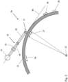
- FIG 1 shows a turbomachine 1, specifically a turbofan engine, in an axial section.
- the turbomachine 1 is functionally divided into a compressor 1a, a combustion chamber 1b and a turbine 1c. Both the compressor 1a and the turbine 1c are each constructed of multiple stages. Each of the stages consists of a ring of guide vanes 5 and a ring of rotor blades 6 .
- the reference numeral 7 designates the gas duct, ie the compressor gas duct in the case of the compressor 1a or the hot gas duct in the case of the turbine 1c.
- the intake air is compressed, it is then in the downstream combustion chamber 1b burned with added kerosene.
- the hot gas flows through the hot-gas duct and thereby drives the moving blade rings 6 which rotate about a ring axis 2 .
- ⁇ guide vane rings 5 of the compressor 1a are equipped with adjustable vanes 10, which can be adjusted to adapt the angle of attack.
- the adjustment axis, not shown here, of a respective adjustment vane 10 lies essentially radially to the ring axis 2, which coincides with a longitudinal axis of the turbomachine.
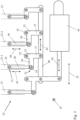
- FIG 2 shows an adjustment arrangement 20 according to the invention, with which the adjustable vanes 10 can be adjusted. It has an adjusting ring 21, with each guide vane ring 5 being assigned a respective adjusting ring 21 and these adjusting rings 21 being offset axially with respect to one another, ie spaced apart from one another in an axial direction 22.
- the adjusting rings 21 can be rotated, namely offset in the direction of rotation 26, via a gear mechanism 25, which is described in detail below.
- This rotational offset 27 of the adjusting ring 21 is transferred to the respective adjusting blade 10 via a respective lever 28 (not shown in detail), which results in the change in the flow angle described.
- figure 3 shows the gear 25 in a radial plan view, which in the present example is designed for the simultaneous actuation of four axially consecutive vane rings 5.
- the corresponding adjustment rings 21 are indicated by dashed lines.
- the adjustment mechanism is discussed below as an example using the second adjustment ring 21 from the left (hereinafter also "first adjustment ring 21.1”), and this applies analogously to the other adjustment rings 21.
- a push rod 30 is provided for coupling to the adjusting ring 21 , which is coupled to the adjusting ring 21 at a first coupling point 31 and to a lever 33 at a second coupling point 32 .
- the coupling points 31, 32 are each implemented via a ball joint 34.
- the lever 33 is rotatably mounted at a pivot point 35 and has a load arm 36 and a force arm 37 .
- the push rod 30 is coupled to the load arm 36, while a coupling rod 40 is coupled to the force arm 37. This extends along the axial direction 22 and connects the individual guide vane rings 5 to one another.
- An axial offset 42 can be generated by an actuator 41 and transferred to the coupling rod 40, this axial offset 42 being converted into an offset 43 of the push rod 30 by the rotatable mounting of the lever 33, as a result of which the adjusting ring 21 is rotated.
- the lever 33 is arranged between the coupling rod 40 and the push rod 30 , the latter extending away from the lever 33 , facing away from the coupling rod 40 . Accordingly, the push rod 30 is arranged completely on one side of the lever 33, both coupling points 31, 32 are in the radial view (looking at it in the radial direction 47) on the same side.
- the entire transmission 25 can thus be aligned essentially tangentially to the adjusting ring 21, compare figure 2 for illustration.
- the plane 45 spanned by the lever 33 can be seen schematically; this plane and thus the lever 33 as well as the connecting rod 30 lie essentially parallel to a tangent 46.
- a second lever 53 is also referenced as an example, which also has a load arm 56 and a force arm 57 and is rotatably mounted at a pivot point 55 .
- the second lever 53 is also connected to the coupling rod 40 and converts the axial offset 42 into an offset 58 of the second connecting rod 59 and thus of the associated adjusting ring 21 ("second adjusting ring 21.2").
- the levers 33, 53 differ in the respective dimensioning of the load arm 36, 56 and the power arm 37, 57.
- FIG 4 shows for comparison a transmission 65 not designed according to the invention, in which the connecting rods 66 do not extend away from the coupling rod 76, but rather cross it in the radial view.
- the transmission 65 is therefore designed with a kink, which is shown in the axial view figure 5 becomes clear.
- the connecting rods 66 are deflected by an angle 77 in relation to the rest of the transmission 65, which results in an oblique introduction of force, which is prone to wear and can result in inaccuracies.
Landscapes
- Engineering & Computer Science (AREA)
- Mechanical Engineering (AREA)
- General Engineering & Computer Science (AREA)
- Chemical & Material Sciences (AREA)
- Combustion & Propulsion (AREA)
- Physics & Mathematics (AREA)
- Fluid Mechanics (AREA)
- Structures Of Non-Positive Displacement Pumps (AREA)
Applications Claiming Priority (1)
| Application Number | Priority Date | Filing Date | Title |
|---|---|---|---|
| DE102021123772.6A DE102021123772A1 (de) | 2021-09-14 | 2021-09-14 | Verstellanordnung für verstellschaufeln einer strömungsmaschine |
Publications (1)
| Publication Number | Publication Date |
|---|---|
| EP4148236A1 true EP4148236A1 (fr) | 2023-03-15 |
Family
ID=83081333
Family Applications (1)
| Application Number | Title | Priority Date | Filing Date |
|---|---|---|---|
| EP22192081.2A Pending EP4148236A1 (fr) | 2021-09-14 | 2022-08-25 | Dispositif de réglage pour aubes à calage variable d'une turbomachine |
Country Status (3)
| Country | Link |
|---|---|
| US (1) | US11891918B2 (fr) |
| EP (1) | EP4148236A1 (fr) |
| DE (1) | DE102021123772A1 (fr) |
Families Citing this family (1)
| Publication number | Priority date | Publication date | Assignee | Title |
|---|---|---|---|---|
| DE102023112223A1 (de) | 2023-05-10 | 2024-11-14 | MTU Aero Engines AG | Kupplungsvorrichtung zum Verbinden von zwei Wellen, Verstellsystem zur Verstellung von variablen Verdichterstufen eines Axialverdichters einer Strömungsmaschine, Axialverdichter für eine Strömungsmaschine, sowie Strömungsmaschine |
Citations (7)
| Publication number | Priority date | Publication date | Assignee | Title |
|---|---|---|---|---|
| US2858062A (en) * | 1955-01-24 | 1958-10-28 | Gen Electric | Variable stator mechanism |
| FR1246176A (fr) * | 1959-01-03 | 1960-11-18 | Entwicklungsbau Pirna Veb | Compresseur axial |
| US2999630A (en) * | 1957-08-08 | 1961-09-12 | Gen Electric | Compressor |
| US5692879A (en) * | 1995-09-27 | 1997-12-02 | Societe Nationale D'etude Et De Construction De Moteurs D'aviation Snecma | Control device for a stage of blades with variable pitch |
| US6398483B1 (en) * | 1999-06-10 | 2002-06-04 | Snecma Moteurs | Protection device for protecting control mechanism of inlet guide-vanes of turbojet engine |
| US20050129510A1 (en) * | 2003-06-20 | 2005-06-16 | Snecma Moteurs | Variable pitch device for two blade stages fixed onto a turbojet |
| EP1724471A2 (fr) * | 2005-05-17 | 2006-11-22 | Snecma | Système de commande d'étages d'aubes de stator à angle de calage variable de turbomachine |
Family Cites Families (10)
| Publication number | Priority date | Publication date | Assignee | Title |
|---|---|---|---|---|
| US2933234A (en) * | 1954-12-28 | 1960-04-19 | Gen Electric | Compressor stator assembly |
| US3861822A (en) | 1974-02-27 | 1975-01-21 | Gen Electric | Duct with vanes having selectively variable pitch |
| US3873230A (en) | 1974-04-10 | 1975-03-25 | United Aircraft Corp | Stator vane actuating mechanism |
| US4295784A (en) | 1979-09-26 | 1981-10-20 | United Technologies Corporation | Variable stator |
| US4720237A (en) | 1986-02-24 | 1988-01-19 | United Technologies Corporation | Unison ring actuator assembly |
| JPH0219698A (ja) * | 1988-07-07 | 1990-01-23 | Hitachi Ltd | ベーンコントロール装置 |
| DE3913102C1 (fr) | 1989-04-21 | 1990-05-31 | Mtu Muenchen Gmbh | |
| US9394804B2 (en) * | 2012-01-24 | 2016-07-19 | Florida Institute Of Technology | Apparatus and method for rotating fluid controlling vanes in small turbine engines and other applications |
| DE102016212767A1 (de) | 2016-07-13 | 2018-01-18 | MTU Aero Engines AG | Verstellbares Turbomaschinen-Schaufelgitter |
| US11105219B2 (en) | 2019-07-03 | 2021-08-31 | Raytheon Technologies Corporation | Vane angle system accuracy improvement |
-
2021
- 2021-09-14 DE DE102021123772.6A patent/DE102021123772A1/de active Pending
-
2022
- 2022-08-25 EP EP22192081.2A patent/EP4148236A1/fr active Pending
- 2022-09-12 US US17/931,345 patent/US11891918B2/en active Active
Patent Citations (7)
| Publication number | Priority date | Publication date | Assignee | Title |
|---|---|---|---|---|
| US2858062A (en) * | 1955-01-24 | 1958-10-28 | Gen Electric | Variable stator mechanism |
| US2999630A (en) * | 1957-08-08 | 1961-09-12 | Gen Electric | Compressor |
| FR1246176A (fr) * | 1959-01-03 | 1960-11-18 | Entwicklungsbau Pirna Veb | Compresseur axial |
| US5692879A (en) * | 1995-09-27 | 1997-12-02 | Societe Nationale D'etude Et De Construction De Moteurs D'aviation Snecma | Control device for a stage of blades with variable pitch |
| US6398483B1 (en) * | 1999-06-10 | 2002-06-04 | Snecma Moteurs | Protection device for protecting control mechanism of inlet guide-vanes of turbojet engine |
| US20050129510A1 (en) * | 2003-06-20 | 2005-06-16 | Snecma Moteurs | Variable pitch device for two blade stages fixed onto a turbojet |
| EP1724471A2 (fr) * | 2005-05-17 | 2006-11-22 | Snecma | Système de commande d'étages d'aubes de stator à angle de calage variable de turbomachine |
Also Published As
| Publication number | Publication date |
|---|---|
| DE102021123772A1 (de) | 2023-03-16 |
| US11891918B2 (en) | 2024-02-06 |
| US20230077444A1 (en) | 2023-03-16 |
Similar Documents
| Publication | Publication Date | Title |
|---|---|---|
| EP3283733B1 (fr) | Dispositif d'actionnement des aubes de guidage variables et turbomachine | |
| EP3283732B1 (fr) | Dispositif de réglage d'aubes directrices et turbomachine | |
| EP3269941B1 (fr) | Grille d'aube réglable pour turbomachines | |
| CH702692B1 (de) | Variable Leitschaufel und Verfahren zur Beseitigung einer aerodynamischen Erregung. | |
| DE102014104318A1 (de) | Strömungsmanipulationsanordnung für einen Turbinenauslassdiffusor | |
| EP2650490A2 (fr) | Dispositif de réglage d'aube directrice d'une turbine à gaz | |
| DE102011000143A1 (de) | Verfahren und Einrichtung für eine segmentierte Turbinenschaufelanordnung | |
| DE102019200885A1 (de) | Leitgitter für eine Strömungsmaschine | |
| CH709266B1 (de) | Turbinenschaufel und Verfahren zum Auswuchten eines Spitzendeckbandes einer Turbinenschaufel und Gasturbine. | |
| DE102007050916A1 (de) | Verfahren und Vorrichtung zum Zusammenbau von Gasturbinen-Triebwerken | |
| EP1624192A1 (fr) | Aube de rouet pour compresseur axial | |
| EP2730751B1 (fr) | Dispositif de réglage d'aubes directrices d'une turbine à gaz | |
| EP4148236A1 (fr) | Dispositif de réglage pour aubes à calage variable d'une turbomachine | |
| EP3176386B1 (fr) | Système de virole interne, virole interne, boîtier intermédiaire et turbomachine associés | |
| EP4230846B1 (fr) | Levier pour le réglage d'une aube à calage variable | |
| WO2022128354A1 (fr) | Composant d'aube, son procédé de production, et turbine à gaz | |
| WO2005045202A1 (fr) | Dispositif de reglage d'aubes directrices | |
| DE10352789B4 (de) | Gasturbine | |
| DE102011052037A1 (de) | Strömungsteileranordnung für Dampfturboantrieb und Verfahren | |
| DE19909899A1 (de) | Schaufeln mit veränderbarer Profilgeometrie | |
| EP3219921B1 (fr) | Aube directrice reglable de turbomachines, turbo-machine et méthode de fabrication | |
| DE102004026365B4 (de) | Einrichtung zur Unwuchtkompensation | |
| DE102022112652A1 (de) | Vorrichtung zum synchronen Verstellen einer Vielzahl von variablen Verdichterstufen für einen Axialverdichter einer Strömungsmaschine, sowie eine Strömungsmaschine | |
| EP3636880A1 (fr) | Roue de turbine | |
| DE102023127736A1 (de) | Leitschaufelverstellvorrichtung und Strömungsmaschine |
Legal Events
| Date | Code | Title | Description |
|---|---|---|---|
| PUAI | Public reference made under article 153(3) epc to a published international application that has entered the european phase |
Free format text: ORIGINAL CODE: 0009012 |
|
| STAA | Information on the status of an ep patent application or granted ep patent |
Free format text: STATUS: THE APPLICATION HAS BEEN PUBLISHED |
|
| AK | Designated contracting states |
Kind code of ref document: A1 Designated state(s): AL AT BE BG CH CY CZ DE DK EE ES FI FR GB GR HR HU IE IS IT LI LT LU LV MC MK MT NL NO PL PT RO RS SE SI SK SM TR |
|
| STAA | Information on the status of an ep patent application or granted ep patent |
Free format text: STATUS: REQUEST FOR EXAMINATION WAS MADE |
|
| 17P | Request for examination filed |
Effective date: 20230915 |
|
| RBV | Designated contracting states (corrected) |
Designated state(s): AL AT BE BG CH CY CZ DE DK EE ES FI FR GB GR HR HU IE IS IT LI LT LU LV MC MK MT NL NO PL PT RO RS SE SI SK SM TR |
|
| STAA | Information on the status of an ep patent application or granted ep patent |
Free format text: STATUS: EXAMINATION IS IN PROGRESS |
|
| 17Q | First examination report despatched |
Effective date: 20250102 |