EP4148254A1 - Ensemble pour une nacelle d'aéronef et comportant un panneau support, une protection thermique et un système de fixation - Google Patents
Ensemble pour une nacelle d'aéronef et comportant un panneau support, une protection thermique et un système de fixation Download PDFInfo
- Publication number
- EP4148254A1 EP4148254A1 EP22194436.6A EP22194436A EP4148254A1 EP 4148254 A1 EP4148254 A1 EP 4148254A1 EP 22194436 A EP22194436 A EP 22194436A EP 4148254 A1 EP4148254 A1 EP 4148254A1
- Authority
- EP
- European Patent Office
- Prior art keywords
- slider
- thermal protection
- support panel
- ball
- cap
- Prior art date
- Legal status (The legal status is an assumption and is not a legal conclusion. Google has not performed a legal analysis and makes no representation as to the accuracy of the status listed.)
- Granted
Links
Images

Classifications
-
- F—MECHANICAL ENGINEERING; LIGHTING; HEATING; WEAPONS; BLASTING
- F02—COMBUSTION ENGINES; HOT-GAS OR COMBUSTION-PRODUCT ENGINE PLANTS
- F02K—JET-PROPULSION PLANTS
- F02K1/00—Plants characterised by the form or arrangement of the jet pipe or nozzle; Jet pipes or nozzles peculiar thereto
- F02K1/78—Other construction of jet pipes
- F02K1/82—Jet pipe walls, e.g. liners
- F02K1/822—Heat insulating structures or liners, cooling arrangements, e.g. post combustion liners; Infrared radiation suppressors
-
- B—PERFORMING OPERATIONS; TRANSPORTING
- B64—AIRCRAFT; AVIATION; COSMONAUTICS
- B64D—EQUIPMENT FOR FITTING IN OR TO AIRCRAFT; FLIGHT SUITS; PARACHUTES; ARRANGEMENT OR MOUNTING OF POWER PLANTS OR PROPULSION TRANSMISSIONS IN AIRCRAFT
- B64D29/00—Power-plant nacelles, fairings or cowlings
- B64D29/06—Attaching of nacelles, fairings or cowlings
-
- B—PERFORMING OPERATIONS; TRANSPORTING
- B64—AIRCRAFT; AVIATION; COSMONAUTICS
- B64C—AEROPLANES; HELICOPTERS
- B64C7/00—Structures or fairings not otherwise provided for
- B64C7/02—Nacelles
-
- B—PERFORMING OPERATIONS; TRANSPORTING
- B64—AIRCRAFT; AVIATION; COSMONAUTICS
- B64D—EQUIPMENT FOR FITTING IN OR TO AIRCRAFT; FLIGHT SUITS; PARACHUTES; ARRANGEMENT OR MOUNTING OF POWER PLANTS OR PROPULSION TRANSMISSIONS IN AIRCRAFT
- B64D29/00—Power-plant nacelles, fairings or cowlings
-
- F—MECHANICAL ENGINEERING; LIGHTING; HEATING; WEAPONS; BLASTING
- F02—COMBUSTION ENGINES; HOT-GAS OR COMBUSTION-PRODUCT ENGINE PLANTS
- F02C—GAS-TURBINE PLANTS; AIR INTAKES FOR JET-PROPULSION PLANTS; CONTROLLING FUEL SUPPLY IN AIR-BREATHING JET-PROPULSION PLANTS
- F02C7/00—Features, components parts, details or accessories, not provided for in, or of interest apart form groups F02C1/00 - F02C6/00; Air intakes for jet-propulsion plants
- F02C7/24—Heat or noise insulation
-
- F—MECHANICAL ENGINEERING; LIGHTING; HEATING; WEAPONS; BLASTING
- F16—ENGINEERING ELEMENTS AND UNITS; GENERAL MEASURES FOR PRODUCING AND MAINTAINING EFFECTIVE FUNCTIONING OF MACHINES OR INSTALLATIONS; THERMAL INSULATION IN GENERAL
- F16B—DEVICES FOR FASTENING OR SECURING CONSTRUCTIONAL ELEMENTS OR MACHINE PARTS TOGETHER, e.g. NAILS, BOLTS, CIRCLIPS, CLAMPS, CLIPS OR WEDGES; JOINTS OR JOINTING
- F16B21/00—Means for preventing relative axial movement of a pin, spigot, shaft or the like and a member surrounding it; Stud-and-socket releasable fastenings
- F16B21/10—Means for preventing relative axial movement of a pin, spigot, shaft or the like and a member surrounding it; Stud-and-socket releasable fastenings by separate parts
- F16B21/16—Means for preventing relative axial movement of a pin, spigot, shaft or the like and a member surrounding it; Stud-and-socket releasable fastenings by separate parts with grooves or notches in the pin or shaft
- F16B21/165—Means for preventing relative axial movement of a pin, spigot, shaft or the like and a member surrounding it; Stud-and-socket releasable fastenings by separate parts with grooves or notches in the pin or shaft with balls or rollers
-
- F—MECHANICAL ENGINEERING; LIGHTING; HEATING; WEAPONS; BLASTING
- F16—ENGINEERING ELEMENTS AND UNITS; GENERAL MEASURES FOR PRODUCING AND MAINTAINING EFFECTIVE FUNCTIONING OF MACHINES OR INSTALLATIONS; THERMAL INSULATION IN GENERAL
- F16B—DEVICES FOR FASTENING OR SECURING CONSTRUCTIONAL ELEMENTS OR MACHINE PARTS TOGETHER, e.g. NAILS, BOLTS, CIRCLIPS, CLAMPS, CLIPS OR WEDGES; JOINTS OR JOINTING
- F16B5/00—Joining sheets or plates, e.g. panels, to one another or to strips or bars parallel to them
- F16B5/06—Joining sheets or plates, e.g. panels, to one another or to strips or bars parallel to them by means of clamps or clips
- F16B5/0607—Joining sheets or plates, e.g. panels, to one another or to strips or bars parallel to them by means of clamps or clips joining sheets or plates to each other
- F16B5/0621—Joining sheets or plates, e.g. panels, to one another or to strips or bars parallel to them by means of clamps or clips joining sheets or plates to each other in parallel relationship
- F16B5/0642—Joining sheets or plates, e.g. panels, to one another or to strips or bars parallel to them by means of clamps or clips joining sheets or plates to each other in parallel relationship the plates being arranged one on top of the other and in full close contact with each other
-
- F—MECHANICAL ENGINEERING; LIGHTING; HEATING; WEAPONS; BLASTING
- F16—ENGINEERING ELEMENTS AND UNITS; GENERAL MEASURES FOR PRODUCING AND MAINTAINING EFFECTIVE FUNCTIONING OF MACHINES OR INSTALLATIONS; THERMAL INSULATION IN GENERAL
- F16L—PIPES; JOINTS OR FITTINGS FOR PIPES; SUPPORTS FOR PIPES, CABLES OR PROTECTIVE TUBING; MEANS FOR THERMAL INSULATION IN GENERAL
- F16L59/00—Thermal insulation in general
- F16L59/12—Arrangements for supporting insulation from the wall or body insulated, e.g. by means of spacers between pipe and heat-insulating material; Arrangements specially adapted for supporting insulated bodies
-
- B—PERFORMING OPERATIONS; TRANSPORTING
- B64—AIRCRAFT; AVIATION; COSMONAUTICS
- B64C—AEROPLANES; HELICOPTERS
- B64C1/00—Fuselages; Constructional features common to fuselages, wings, stabilising surfaces or the like
- B64C1/40—Sound or heat insulation, e.g. using insulation blankets
- B64C1/403—Arrangement of fasteners specially adapted therefor, e.g. of clips
-
- F—MECHANICAL ENGINEERING; LIGHTING; HEATING; WEAPONS; BLASTING
- F05—INDEXING SCHEMES RELATING TO ENGINES OR PUMPS IN VARIOUS SUBCLASSES OF CLASSES F01-F04
- F05D—INDEXING SCHEME FOR ASPECTS RELATING TO NON-POSITIVE-DISPLACEMENT MACHINES OR ENGINES, GAS-TURBINES OR JET-PROPULSION PLANTS
- F05D2260/00—Function
- F05D2260/20—Heat transfer, e.g. cooling
- F05D2260/231—Preventing heat transfer
-
- F—MECHANICAL ENGINEERING; LIGHTING; HEATING; WEAPONS; BLASTING
- F05—INDEXING SCHEMES RELATING TO ENGINES OR PUMPS IN VARIOUS SUBCLASSES OF CLASSES F01-F04
- F05D—INDEXING SCHEME FOR ASPECTS RELATING TO NON-POSITIVE-DISPLACEMENT MACHINES OR ENGINES, GAS-TURBINES OR JET-PROPULSION PLANTS
- F05D2260/00—Function
- F05D2260/30—Retaining components in desired mutual position
- F05D2260/36—Retaining components in desired mutual position by a form fit connection, e.g. by interlocking
Definitions
- the present invention relates to an assembly for a nacelle of an aircraft engine comprising a support panel, a thermal protection and a fixing system which ensures the fixing of the thermal protection on the support panel, a nacelle of an engine of aircraft comprising at least one such assembly, as well as an aircraft comprising at least one such nacelle.
- An aircraft conventionally comprises at least one turbofan engine which comprises an engine constituting a core housed in a nacelle.
- the nacelle comprises a fixed internal structure (also called IFS “Internai Fixed Structure” in Anglo-Saxon) surrounding the engine and external covers arranged around the fixed internal structure.
- the internal structure and the outer cowls delimit between them a secondary channel in which circulates a secondary flow of air originating from an air inlet arranged at the front of the nacelle, while a primary flow circulates in the engine.
- the internal structure is subjected to very high temperatures due to the proximity of the motor and it is therefore desirable to attach thermal protection to it.
- An object of the present invention is to propose an assembly for a nacelle of an aircraft engine comprising a support panel such as for example a panel of an internal structure, thermal protection and a fastening system which ensures the fastening of the thermal protection on the support panel, where fixing is done quickly and easily.
- Such an assembly allows simple and quick fixing of the thermal protection on the support panel, also allowing easy dismantling if necessary.
- the passage from the blocking position to the unlocking position of the slider consists of pushing the slider into the sleeve, the slider carries a stop and the sleeve has a chamber in which the stop moves and one face of which constitutes a counter abutment against which the abutment bears in the locking position, and the slider has, in the locking position, an end which protrudes from the cap and which is traversed by a bore in which a locking means is inserted.
- the assembly comprises a cylindrical washer which fits onto the female part to fill the space between the support panel and the thermal protection at the level of the hole.
- the assembly comprises an eyelet which is positioned along the edges of the corresponding hole of the thermal protection, which fits onto the corresponding cylindrical wall and bears against the base .
- each male part is secured to the thermal protection.
- the assembly comprises a cylindrical washer which fits onto the female part to fill the space between the support panel and the thermal protection at the level of the hole, the thermal protection comprises on its face oriented against the hat, a support plate glued to said face and the hat is fixed to the eyelet and to the support plate.
- the thermal protection comprises, on its face oriented against the cap, a support plate bonded to said face and the cap is fixed to the support plate.
- the male part comprises a return means which forces the slider into the locking position.
- the invention also proposes a nacelle of a turbofan engine, said nacelle comprising a fixed internal structure and an assembly according to one of the preceding variants, where the support panel is a panel of the fixed internal structure.
- the invention also proposes an aircraft comprising at least one nacelle according to the previous variant.
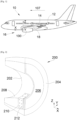
- FIG. 1 shows an aircraft 10 which comprises a fuselage 12 on each side of which is fixed a wing 14 which carries at least one turbofan engine 16 supported by a mast 18 which secures the turbofan engine 16 under the wing 14.
- the longitudinal axis of the turbofan engine 16 is called X, which is parallel to the longitudinal axis of the aircraft 10 and oriented positively towards the front of the aircraft 10.
- Y the transverse axis which is horizontal when the aircraft 10 is on the ground
- Z the vertical axis when the aircraft 10 is on the ground, these three axes X, Y and Z being mutually orthogonal.
- the turbofan engine 16 comprises a nacelle 100 and an engine forming a core which is housed inside the nacelle 100 which conventionally comprises two modules fixed to the mast 18 on either side of a vertical median plane XZ.
- FIG. 2 schematically shows a module 200 of the nacelle 100.
- the module 200 comprises among other things a fixed internal structure 202 (also called IFS "Internai Fixed Structure” in English) surrounding the engine and external covers 204 arranged around the fixed internal structure 202.
- a fixed internal structure 202 also called IFS "Internai Fixed Structure” in English
- IFS Internai Fixed Structure
- the internal structure 202 and the outer covers 204 delimit between them a secondary channel 206 in which circulates a secondary flow of air coming from an air inlet arranged at the front of the nacelle 100.
- the internal structure 202 consists, among other things, of a support panel 208 which surrounds the motor and which is subjected to high temperatures.
- the protection of the support panel 208 is ensured by thermal protections 210.
- a single heat shield 210 is shown, but a plurality of such heat shields 210 are attached to cover the surface of the support panel 208 to be protected.
- Each thermal protection 210 takes the form of an additional panel fixed to the support panel 208 via a plurality of fixing systems 212 and made of a thermally insulating material.
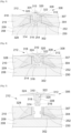
- THE Figs. 3 to 5 show a first embodiment of the invention in different assembly positions.
- the thermal protection 210 and the support panel 208 are in contact against each other at the level of a contact surface 209.
- the fixing system 212 comprises a female part 302 which here is a part of revolution around an axis of revolution generally perpendicular to the support panel 208 and which has a cylindrical wall 252 delimiting a free space and a base 250 secured to the support panel 208 and the cylindrical wall 252.
- the cylindrical wall 252 is of revolution around the axis of revolution and has an opening oriented opposite the support panel 208.
- the cylindrical wall 252 has on the inside a circular shoulder 304 around the axis of revolution which projects inwardly from the cylindrical wall 252.
- the shoulder 304 is provided to allow the placement of balls behind the shoulder 304 relative to the opening.
- the shoulder 304 is therefore at a distance from the bottom of the female part 302 corresponding to the base 250.
- the thermal protection 210 has a hole 307 which passes through it parallel to the axis of revolution.
- the fastening system 212 comprises a male part 306 which is also here of revolution around the axis of revolution.
- the male part 306 comprises a sleeve 308 which is inserted into the female part 302, and more precisely into the free space delimited by the cylindrical wall 252 to ensure the fixing of the thermal protection 210 to the support panel 208.
- the sleeve 308 is pierced with a main bore 254 coaxial with the axis of revolution and the male part 306 comprises a slider 310 movable in translation in the main bore 254.
- the male part 306 also comprises a cap 312 integral with the sheath 308 and which comes into bearing against the face of the thermal protection 210 on the side opposite to the contact surface 209.
- the male part 306 also comprises a plurality of balls 314 distributed angularly around the axis of revolution.
- the sleeve 308 has a secondary bore 316 perpendicular to the main bore 254 and which opens on a first side into said main bore 254 and on a second side outside the sleeve 308.
- Each ball 314 is placed in the corresponding secondary bore 316 and is thus movable in translation along said secondary bore 316 between a locking position ( Fig. 3 ) in which the ball 314 protrudes at the level of the second side and therefore projects relative to the sheath 308 and an unlocking position ( Figs. 4 and 5 ) in which the ball 314 does not overflow at the level of the second side and is therefore retracted inside the sleeve 308.
- the diameter of the secondary bore 316 at the level of said second side is less than the diameter of the ball 314 while ensuring the exit from the sheath 308 of part of the ball 314.
- the slider 310 For each ball 314, the slider 310 comprises a cell 318 taking the form of a half-ball which sinks into the slider 310.
- the slider 310 is movable in translation between a locking position and an unlocking position.
- locking position Fig. 3
- the slider 310 is in a position such that the cells 318 are not opposite the balls 314.
- the balls 314 are then against the slider 310 which forces the balls 314 into the locking position and into the locking position.
- unlock Figs. 4 and 5
- the slider 310 is in a position such that the cells 318 are opposite the balls 314 allowing the balls 314 to pass into the unlocked position.
- the principle of setting up the fixing system 212 consists in placing the thermal protection 210 against the support panel 208 with the female part 302 in the hole 307.
- the male part 306 is brought close to the female part 302 with the slider 310 in the unlocking position and the balls 314 in the unlocking position ( Fig. 5 ).
- the sleeve 308 is introduced through the opening in the cylindrical wall 252 until the balls 314 are brought under the shoulder 304 ( Fig. 4 ) and finally the slider 310 is moved into the blocking position ( Fig. 3 ) so as to force the balls 314 into the locking position under the shoulder 304 so as to block the male part 306.
- the cap 312 bears against the face of the thermal protection 210 on the side opposite the contact surface 209, thus ensuring the fixing of the thermal protection 210 to the support panel 208 by sandwiching the thermal protection 210 between the cap 312 and the support panel 208.
- dismantling consists of starting from the locking and blocking position ( Fig. 5 ), to move (here push) the slider 310 towards the release position ( Fig. 4 ) which releases the balls 314 which are free to move into the unlocked position, then to remove the male part 306 ( Fig. 5 ) by pulling on the male part 306.
- the assembly and disassembly of the thermal protection are therefore relatively simple and quick.
- the assembly according to the invention constituting part of the nacelle 100 then comprises the support panel 208, the thermal protection 210 and the plurality of fastening systems 212.
- the passage from the blocking position to the unlocking position of the slider 310 consists of a depression of the slider 310 in the sleeve 308 and, conversely, the passage from the unlocking position to the blocking position of the slider 310 consists at an outlet of the slider 310 of the sheath 308 at the level of the cap 312.
- the slider 310 carries a stop 320 and the sheath 308 has a chamber in which the stop 320 moves and one face of which constitutes a counter-stop 322 against which the stop 320 comes to bear in the blocking position.
- the slider 310 has, in the locking position, an end which protrudes from the cap 312 and which is traversed by a bore 324 in which a locking means 326, such as a pin, is inserted.
- a locking means 326 such as a pin
- the assembly also comprises a washer 328 of cylindrical shape with a central hole to allow fitting onto the part female 302, and more particularly on the cylindrical wall 252, to fill the space between the support panel 208 and the thermal protection 210 at the level of the hole 307.
- the washer 328 is made of a thermally insulating material.
- washer 328 takes the form of a truncated cone with a central hole.
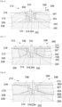
- the assembly comprises an eyelet 602 which is positioned along the edges of the corresponding hole 307 of the thermal protection 210.
- This eyelet 602 fits onto the corresponding cylindrical wall 252 and bears against the base 250.
- the eyelet 602 comprises two flanges which are arranged on either side of the thermal protection 210 and a cylinder which secures the two flanges.
- each male part 306 is integral with the thermal protection 210.
- the attachment is made by rivets 706.
- the assembly comprises an eyelet 702 which is positioned along the edges of the corresponding central hole of the washer 328. As before, this eyelet 702 fits onto the corresponding cylindrical wall 252 and bears against the 250 base.
- the thermal protection 210 comprises on its face oriented against the cap 312, a support plate 704, of the metal plate type, bonded to said face.
- Cap 312 is attached to grommet 702 and backing plate 704.
- the thermal protection 210 comprises on its face oriented against the support panel 208, another support plate 708, of the metal plate type, bonded to said face.
- the thermal protection 210 has on its face oriented against the cap 312, a support plate 804, of the metal plate type, glued to said face and the cap 312 is fixed to the support plate 804.
- the thermal protection 210 comprises on its face oriented against the support panel 208, another support plate 808, of the metal plate type, bonded to said face.
- the male part 306 comprises a return means 902, here a helical spring, which forces the slider 310 into the locking position.
- the return means 902 also facilitates the exit of the slider 310.
- the return means 902 is housed in the chamber carrying the counter-stop 322 and it is constrained between a wall of said chamber and an element of the slider 310, here a stud 904.
- the cap 312 also includes a guard hole 906 which allows the attachment of the locking means 326 when it is not housed in the bore 324 thus avoiding losing it and making it possible to use the locking means 326 to pull on the hat 312.
- guard hole 906 is presented on a particular assembly, it applies to the various embodiments presented above.
- the female part 302 is a one-piece, single-material part, for example made of metal or a composite material.
- Fig. 10 and the Fig. 11 show two variant embodiments of the female part 302 in which the cylindrical wall 252 and the shoulder 304 are made by a metal insert 1002 and the base 250 is made by a base 1004 made of composite material.
- the base 1004 is molded around the insert 1002 to ensure the fixing of the insert 1002.
- the insert 1002 has a flange 1006 which extends outside the insert 1002 and which is embedded in the base 1004 to ensure the fixing of the insert 1002.
- the fixing of the base 250 is carried out for example by gluing to the composite panel 208.
Landscapes
- Engineering & Computer Science (AREA)
- General Engineering & Computer Science (AREA)
- Mechanical Engineering (AREA)
- Chemical & Material Sciences (AREA)
- Combustion & Propulsion (AREA)
- Aviation & Aerospace Engineering (AREA)
- Connection Of Plates (AREA)
Abstract
Description
- La présente invention concerne un ensemble pour une nacelle d'un moteur d'aéronef comportant un panneau support, une protection thermique et un système de fixation qui assure la fixation de la protection thermique sur le panneau support, une nacelle d'un moteur d'aéronef comportant au moins un tel ensemble, ainsi qu'un aéronef comportant au moins une telle nacelle.
- Un aéronef comporte classiquement au moins un turboréacteur double flux qui comporte un moteur constituant un noyau logé dans une nacelle. La nacelle comporte une structure interne fixe (également appelée IFS « Internai Fixed Structure » en Anglo-saxon) entourant le moteur et des capots extérieurs disposés autour de la structure interne fixe.
- La structure interne et les capots extérieurs délimitent entre eux un canal secondaire dans lequel circule un flux secondaire d'air provenant d'une entrée d'air disposée à l'avant de la nacelle, tandis qu'un flux primaire circule dans le moteur.
- La structure interne est soumise à de très fortes températures du fait de la proximité du moteur et il est donc souhaitable d'y fixer des protections thermiques.
- Un objet de la présente invention est de proposer un ensemble pour une nacelle d'un moteur d'aéronef comportant un panneau support comme par exemple un panneau d'une structure interne, une protection thermique et un système de fixation qui assure la fixation de la protection thermique sur le panneau support, où la fixation s'effectue de manière simple et rapide.
- À cet effet, est proposé un ensemble comportant :
- un panneau support d'une structure interne fixe d'une nacelle d'un turboréacteur double flux,
- une protection thermique en contact avec le panneau support au niveau d'une surface de contact, et
- une pluralité de systèmes de fixation assurant la fixation amovible de la protection thermique au panneau support,
- où pour chaque système de fixation, la protection thermique présente un trou qui la traverse,
- où chaque système de fixation comporte :
- une pièce femelle logée dans le trou correspondant, et présentant une embase solidaire du panneau support et une paroi cylindrique délimitant un espace libre et ouvert à l'opposé du panneau support, où la paroi cylindrique présente un épaulement circulaire qui fait saillie vers l'intérieur de la paroi cylindrique, et
- une pièce mâle comportant un fourreau inséré dans la paroi cylindrique et percé d'un alésage principal, un coulisseau mobile en translation dans l'alésage principal et une pluralité de billes, où pour chaque bille, le fourreau présente un alésage secondaire perpendiculaire à l'alésage principal et qui débouche d'un premier côté dans ledit alésage principal et d'un deuxième côté à l'extérieur du fourreau, où chaque bille est placée dans l'alésage secondaire correspondant et est mobile en translation le long dudit alésage secondaire entre une position de verrouillage dans laquelle la bille déborde au niveau du deuxième côté et une position de déverrouillage dans laquelle la bille ne déborde pas au niveau du deuxième côté, où pour chaque bille, le coulisseau comporte une alvéole prenant la forme d'une demi-bille, et où le coulisseau est mobile en translation entre une position de blocage dans laquelle le coulisseau est dans une position telle que les alvéoles ne sont pas en vis-à-vis des billes et telle que les billes sont forcées en position de verrouillage, et une position de déblocage dans laquelle le coulisseau est dans une position telle que les alvéoles sont en vis-à-vis des billes autorisant les billes à passer en position de déverrouillage et où la pièce mâle comporte également un chapeau solidaire du fourreau et qui vient en appui contre la face de la protection thermique du côté opposé à la surface de contact.
- Un tel ensemble permet une fixation simple et rapide de la protection thermique sur le panneau support, permettant également un démontage aisé en cas de besoin.
- Avantageusement, le passage de la position de blocage à la position de déblocage du coulisseau consiste en un enfoncement du coulisseau dans le fourreau, le coulisseau porte une butée et le fourreau présente une chambre dans laquelle se déplace la butée et dont une face constitue une contre-butée contre laquelle la butée vient en appui en position de blocage, et le coulisseau présente, en position de blocage, une extrémité qui dépasse du chapeau et qui est traversée par un perçage dans lequel un moyen de verrouillage est inséré.
- Selon un mode de réalisation particulier, pour chaque pièce femelle, l'ensemble comporte une rondelle de forme cylindrique qui s'emmanche sur la pièce femelle pour combler l'espace entre le panneau support et la protection thermique au niveau du trou.
- Selon un mode de réalisation particulier, pour chaque pièce femelle, l'ensemble comporte un oeillet qui est positionné le long des bords du trou correspondant de la protection thermique, qui s'emmanche sur la paroi cylindrique correspondante et vient en appui contre l'embase.
- Selon un mode de réalisation particulier, chaque pièce mâle est solidaire de la protection thermique.
- Selon un mode de réalisation particulier, pour chaque pièce femelle, l'ensemble comporte une rondelle de forme cylindrique qui s'emmanche sur la pièce femelle pour combler l'espace entre le panneau support et la protection thermique au niveau du trou, la protection thermique comporte sur sa face orientée contre le chapeau, une plaque de soutien collée sur ladite face et le chapeau est fixé à l'œillet et à la plaque de soutien.
- Selon un mode de réalisation particulier, la protection thermique comporte sur sa face orientée contre le chapeau, une plaque de soutien collée sur ladite face et le chapeau est fixé à la plaque de soutien.
- Avantageusement, la pièce mâle comporte un moyen de rappel qui contraint le coulisseau en position de verrouillage.
- L'invention propose également une nacelle d'un turboréacteur double flux, ladite nacelle comportant une structure interne fixe et un ensemble selon l'une des variantes précédentes, où le panneau support est un panneau de la structure interne fixe.
- L'invention propose également un aéronef comportant au moins une nacelle selon la variante précédente.
- Les caractéristiques de l'invention mentionnées ci-dessus, ainsi que d'autres, apparaîtront plus clairement à la lecture de la description suivante d'un exemple de réalisation, ladite description étant faite en relation avec les dessins joints, parmi lesquels :
- [
Fig. 1 ] est une vue de côté d'un aéronef selon l'invention, - [
Fig. 2 ] est une vue en perspective d'une partie d'une nacelle selon l'invention, - [
Fig. 3 ] est une vue en coupe d'un ensemble selon un premier mode de réalisation de l'invention en position assemblée, - [
Fig. 4 ] est une vue similaire à celle de laFig. 3 en position déverrouillée, - [
Fig. 5 ] est une vue similaire à celle de laFig. 3 en position désassemblée, - [
Fig. 6 ] est une vue similaire à celle de laFig. 3 pour un deuxième mode de réalisation de l'invention, - [
Fig. 7 ] est une vue similaire à celle de laFig. 3 pour un troisième mode de réalisation de l'invention, - [
Fig. 8 ] est une vue similaire à celle de laFig. 3 pour un quatrième mode de réalisation de l'invention, - [
Fig. 9 ] est une vue similaire à celle de laFig. 3 pour une variante de l'invention, - [
Fig. 10 ] est une vue en coupe d'une pièce femelle selon une première variante, et - [
Fig. 11 ] est une vue en coupe d'une pièce femelle selon une deuxième variante. - Dans la description qui suit, les termes relatifs à une position sont pris en référence au sens d'avancement d'un aéronef représenté par la flèche 107 de la
Fig. 1 . - La
Fig. 1 montre un aéronef 10 qui comporte un fuselage 12 de chaque côté duquel est fixée une aile 14 qui porte au moins un turboréacteur double flux 16 soutenu par un mât 18 qui assure la fixation du turboréacteur double flux 16 sous l'aile 14. - Dans la description qui suit, et par convention, on appelle X l'axe longitudinal du turboréacteur double flux 16 qui est parallèle à l'axe longitudinal de l'aéronef 10 et orienté positivement vers l'avant de l'aéronef 10, on appelle Y l'axe transversal qui est horizontal lorsque l'aéronef 10 est au sol, et Z l'axe vertical lorsque l'aéronef 10 est au sol, ces trois axes X, Y et Z étant orthogonaux entre eux.
- Le turboréacteur double flux 16 comporte une nacelle 100 et un moteur formant un noyau qui est logé à l'intérieur de la nacelle 100 qui comporte classiquement deux modules fixés au mât 18 de part et d'autre d'un plan médian vertical XZ.
- La
Fig. 2 montre schématiquement un module 200 de la nacelle 100. Le module 200 comporte entre autres une structure interne fixe 202 (également appelée IFS « Internai Fixed Structure » en Anglo-saxon) entourant le moteur et des capots extérieurs 204 disposés autour de la structure interne fixe 202. - La structure interne 202 et les capots extérieurs 204 délimitent entre eux un canal secondaire 206 dans lequel circule un flux secondaire d'air provenant d'une entrée d'air disposée à l'avant de la nacelle 100.
- La structure interne 202 est constituée, entre autres, d'un panneau support 208 qui entoure le moteur et qui est soumis à de fortes températures. Dans le cadre de l'invention, la protection du panneau support 208 est assurée par des protections thermiques 210.
- Dans le mode de réalisation de l'invention, présenté ici, une seule protection thermique 210 est représentée, mais une pluralité de telles protections thermiques 210 sont fixées pour recouvrir la surface du panneau support 208 à protéger.
- Chaque protection thermique 210 prend la forme d'un panneau additionnel fixé au panneau support 208 par l'intermédiaire d'une pluralité de systèmes de fixation 212 et réalisé dans un matériau thermiquement isolant.
- Les
Figs. 3 à 5 montrent un premier mode de réalisation de l'invention dans différentes positions d'assemblage. La protection thermique 210 et le panneau support 208 sont en contact l'un contre l'autre au niveau d'une surface de contact 209. - Le système de fixation 212 comporte une pièce femelle 302 qui est ici une pièce de révolution autour d'un axe de révolution globalement perpendiculaire au panneau support 208 et qui présente une paroi cylindrique 252 délimitant un espace libre et une embase 250 solidaire du panneau support 208 et de la paroi cylindrique 252. La paroi cylindrique 252 est de révolution autour de l'axe de révolution et présente une ouverture orientée à l'opposé du panneau support 208. La paroi cylindrique 252 présente à l'intérieur un épaulement 304 circulaire autour de l'axe de révolution qui fait saillie vers l'intérieur de la paroi cylindrique 252.
- Comme cela est expliqué ci-dessous, l'épaulement 304 est prévu pour permettre la mise en place de billes à l'arrière de l'épaulement 304 par rapport à l'ouverture. L'épaulement 304 est donc à distance du fond de la pièce femelle 302 correspondant à l'embase 250.
- Pour permettre la mise en place de chaque pièce femelle 302, la protection thermique 210 présente un trou 307 qui la traverse parallèlement à l'axe de révolution.
- Le système de fixation 212 comporte une pièce mâle 306 qui est également ici de révolution autour de l'axe de révolution.
- La pièce mâle 306 comporte un fourreau 308 qui s'insère dans la pièce femelle 302, et plus précisément dans l'espace libre délimité par la paroi cylindrique 252 pour assurer la fixation de la protection thermique 210 au panneau support 208. Le fourreau 308 est percé d'un alésage principal 254 coaxial avec l'axe de révolution et la pièce mâle 306 comporte un coulisseau 310 mobile en translation dans l'alésage principal 254. La pièce mâle 306 comporte également un chapeau 312 solidaire du fourreau 308 et qui vient en appui contre la face de la protection thermique 210 du côté opposé à la surface de contact 209.
- La pièce mâle 306 comporte également une pluralité de billes 314 réparties angulairement autour de l'axe de révolution.
- Pour chaque bille 314, le fourreau 308 présente un alésage secondaire 316 perpendiculaire à l'alésage principal 254 et qui débouche d'un premier côté dans ledit alésage principal 254 et d'un deuxième côté à l'extérieur du fourreau 308. Chaque bille 314 est placée dans l'alésage secondaire 316 correspondant et est ainsi mobile en translation le long dudit alésage secondaire 316 entre une position de verrouillage (
Fig. 3 ) dans laquelle la bille 314 déborde au niveau du deuxième côté et est donc en saillie par rapport au fourreau 308 et une position de déverrouillage (Figs. 4 et 5 ) dans laquelle la bille 314 ne déborde pas au niveau du deuxième côté et est donc rentrée à l'intérieur du fourreau 308. - Pour éviter la perte de la bille 314 au niveau du deuxième côté, le diamètre de l'alésage secondaire 316 au niveau dudit deuxième côté est inférieur au diamètre de la bille 314 tout en assurant la sortie du fourreau 308 d'une partie de la bille 314.
- Pour chaque bille 314, le coulisseau 310 comporte une alvéole 318 prenant la forme d'une demi-bille qui s'enfonce dans le coulisseau 310.
- Le coulisseau 310 est mobile en translation entre une position de blocage et une position de déblocage. En position de blocage (
Fig. 3 ), le coulisseau 310 est dans une position telle que les alvéoles 318 ne sont pas en vis-à-vis des billes 314. Les billes 314 sont alors contre le coulisseau 310 ce qui force les billes 314 en position de verrouillage et en position de déblocage (Figs. 4 et 5 ), le coulisseau 310 est dans une position telle que les alvéoles 318 sont en vis-à-vis des billes 314 autorisant les billes 314 à passer en position de déverrouillage. - Le principe de mise en place du système de fixation 212 consiste à placer la protection thermique 210 contre le panneau support 208 avec la pièce femelle 302 dans le trou 307.
- La pièce mâle 306 est approchée de la pièce femelle 302 avec le coulisseau 310 en position de déblocage et les billes 314 en position de déverrouillage (
Fig. 5 ). Le fourreau 308 est introduit par l'ouverture dans la paroi cylindrique 252 jusqu'à amener les billes 314 sous l'épaulement 304 (Fig. 4 ) et enfin le coulisseau 310 est déplacé en position de blocage (Fig. 3 ) de manière à forcer les billes 314 en position de verrouillage sous l'épaulement 304 de manière à bloquer la pièce mâle 306. - Le passage de la position de déblocage à la position de blocage s'effectue ici par un retrait limité du coulisseau 310 du côté du chapeau 312.
- En même temps, le chapeau 312 est en appui contre la face de la protection thermique 210 du côté opposé à la surface de contact 209, assurant ainsi la fixation de la protection thermique 210 au panneau support 208 par prise en sandwich de la protection thermique 210 entre le chapeau 312 et le panneau support 208.
- À l'inverse le démontage consiste à partir de la position de verrouillage et de blocage (
Fig. 5 ), à déplacer (ici enfoncer) le coulisseau 310 vers la position de déblocage (Fig. 4 ) ce qui libère les billes 314 qui sont libres de passer en position de déverrouillage, puis à retirer la pièce mâle 306 (Fig. 5 ) en tirant sur la pièce mâle 306. - Le montage et le démontage de la protection thermique sont donc relativement simples et rapides.
- L'ensemble selon l'invention constituant une partie de la nacelle 100 comporte alors le panneau support 208, la protection thermique 210 et la pluralité de systèmes de fixation 212.
- Dans le mode de réalisation des
Figs. 3 à 5 , le passage de la position de blocage à la position de déblocage du coulisseau 310 consiste en un enfoncement du coulisseau 310 dans le fourreau 308 et, à l'inverse, le passage de la position de déblocage à la position de blocage du coulisseau 310 consiste en une sortie du coulisseau 310 du fourreau 308 au niveau du chapeau 312. - Pour éviter la sortie du coulisseau 310 au-delà de la position de blocage, le coulisseau 310 porte une butée 320 et le fourreau 308 présente une chambre dans laquelle se déplace la butée 320 et dont une face constitue une contre-butée 322 contre laquelle la butée 320 vient en appui en position de blocage.
- Pour empêcher un enfoncement non souhaité du coulisseau 310, le coulisseau 310 présente, en position de blocage, une extrémité qui dépasse du chapeau 312 et qui est traversée par un perçage 324 dans lequel un moyen de verrouillage 326, tel qu'une goupille, est inséré. Le passage vers la position de déblocage nécessite alors le retrait préalable du moyen de verrouillage 326.
- Dans le mode de réalisation des
Figs. 3 à 5 , l'ensemble comporte également une rondelle 328 de forme cylindrique avec un trou central pour permettre l'emmanchement sur la pièce femelle 302, et plus particulièrement sur la paroi cylindrique 252, pour combler l'espace entre le panneau support 208 et la protection thermique 210 au niveau du trou 307. La rondelle 328 est réalisée dans un matériau thermiquement isolant. Ici, la rondelle 328 prend la forme d'un tronc de cône avec un trou central. - Dans le deuxième mode de réalisation de l'invention représenté à la
Fig. 6 , pour chaque pièce femelle 302, l'ensemble comporte un œillet 602 qui est positionné le long des bords du trou 307 correspondant de la protection thermique 210. Cet oeillet 602 s'emmanche sur la paroi cylindrique 252 correspondante et vient en appui contre l'embase 250. L'oeillet 602 comporte deux flasques qui sont disposés de part et d'autre de la protection thermique 210 et un cylindre qui solidarise les deux flasques. - Dans le troisième mode de réalisation de l'invention représenté à la
Fig. 7 et dans le quatrième mode de réalisation de l'invention représenté à laFig. 8 , chaque pièce mâle 306 est solidaire de la protection thermique 210. Ici la solidarisation est réalisée par des rivets 706. - Dans le troisième mode de réalisation de l'invention représenté à la
Fig. 7 , pour chaque pièce femelle 302, l'ensemble comporte un œillet 702 qui est positionné le long des bords du trou central correspondant de la rondelle 328. Comme précédemment, cet oeillet 702 s'emmanche sur la paroi cylindrique 252 correspondante et vient en appui contre l'embase 250. - En outre, la protection thermique 210 comporte sur sa face orientée contre le chapeau 312, une plaque de soutien 704, du type plaque métallique, collée sur ladite face.
- Le chapeau 312 est fixé à l'œillet 702 et à la plaque de soutien 704.
- Dans le mode de réalisation de l'invention présenté ici, la protection thermique 210 comporte sur sa face orientée contre le panneau support 208, une autre plaque de soutien 708, du type plaque métallique, collée sur ladite face.
- Dans le quatrième mode de réalisation de l'invention représenté à la
Fig. 8 , la protection thermique 210 comporte sur sa face orientée contre le chapeau 312, une plaque de soutien 804, du type plaque métallique, collée sur ladite face et le chapeau 312 est fixé à la plaque de soutien 804. - Dans le mode de réalisation de l'invention présenté ici, la protection thermique 210 comporte sur sa face orientée contre le panneau support 208, une autre plaque de soutien 808, du type plaque métallique, collée sur ladite face.
- Dans une variante de réalisation de l'invention représentée à la
Fig. 9 , la pièce mâle 306 comporte un moyen de rappel 902, ici un ressort hélicoïdal, qui contraint le coulisseau 310 en position de blocage. Le moyen de rappel 902 facilite également la sortie du coulisseau 310. - Dans le mode de réalisation de l'invention présenté ici, le moyen de rappel 902 est logé dans la chambre portant la contre-butée 322 et il est contraint entre une paroi de ladite chambre et un élément du coulisseau 310, ici un plot 904.
- Bien que ce moyen de rappel 902 soit présenté sur un ensemble particulier, il s'applique aux différents modes de réalisation présentés ci-dessus.
- Le chapeau 312 comporte également un trou de garde 906 qui permet l'accrochage du moyen de verrouillage 326 lorsqu'il n'est pas logé dans le perçage 324 évitant ainsi de le perdre et permettant de se servir du moyen de verrouillage 326 pour tirer sur le chapeau 312.
- Bien que ce trou de garde 906 soit présenté sur un ensemble particulier, il s'applique aux différents modes de réalisation présentés ci-dessus.
- Dans les modes de réalisation des
Figs. 3 à 9 , la pièce femelle 302 est une pièce monobloc et mono-matière, par exemple en métal ou en matériau composite. - La
Fig. 10 et laFig. 11 montrent deux variantes de réalisation de la pièce femelle 302 dans lesquelles la paroi cylindrique 252 et l'épaulement 304 sont réalisés par un insert métallique 1002 et l'embase 250 est réalisée par un socle 1004 réalisé en matériau composite. - Dans le mode de réalisation de la
Fig. 10 , le socle 1004 est surmoulé autour de l'insert 1002 pour assurer la fixation de l'insert 1002. - Dans le mode de réalisation de la
Fig. 11 , l'insert 1002 présente une collerette 1006 qui s'étend à l'extérieur de l'insert 1002 et qui est noyé dans le socle 1004 pour assurer la fixation de l'insert 1002. - Dans chacun des modes de réalisation décrits ci-dessus, la fixation de l'embase 250 est réalisée par exemple par collage au panneau composite 208.
Claims (10)
- Ensemble comportant :- un panneau support (208) d'une structure interne fixe (202) d'une nacelle (100) d'un turboréacteur double flux (106),- une protection thermique (210) en contact avec le panneau support (208) au niveau d'une surface de contact (209), et- une pluralité de systèmes de fixation (212) assurant la fixation amovible de la protection thermique (210) au panneau support (208),où pour chaque système de fixation (212), la protection thermique (210) présente un trou (307) qui la traverse,où chaque système de fixation (212) comporte :- une pièce femelle (302) logée dans le trou (307) correspondant, et présentant une embase (250) solidaire du panneau support (208) et une paroi cylindrique (252) délimitant un espace libre et ouvert à l'opposé du panneau support (208), où la paroi cylindrique (252) présente un épaulement (304) circulaire qui fait saillie vers l'intérieur de la paroi cylindrique (252), et- une pièce mâle (306) comportant un fourreau (308) inséré dans la paroi cylindrique (252) et percé d'un alésage principal (254), un coulisseau (310) mobile en translation dans l'alésage principal (254) et une pluralité de billes (314), où pour chaque bille (314), le fourreau (308) présente un alésage secondaire (316) perpendiculaire à l'alésage principal (254) et qui débouche d'un premier côté dans ledit alésage principal (254) et d'un deuxième côté à l'extérieur du fourreau (308), où chaque bille (314) est placée dans l'alésage secondaire (316) correspondant et est mobile en translation le long dudit alésage secondaire (316) entre une position de verrouillage dans laquelle la bille (314) déborde au niveau du deuxième côté et une position de déverrouillage dans laquelle la bille (314) ne déborde pas au niveau du deuxième côté, où pour chaque bille (314), le coulisseau (310) comporte une alvéole (318) prenant la forme d'une demi-bille, et où le coulisseau (310) est mobile en translation entre une position de blocage dans laquelle le coulisseau (310) est dans une position telle que les alvéoles (318) ne sont pas en vis-à-vis des billes (314) et telle que les billes (314) sont forcées en position de verrouillage, et une position de déblocage dans laquelle le coulisseau (310) est dans une position telle que les alvéoles (318) sont en vis-à-vis des billes (314) autorisant les billes (314) à passer en position de déverrouillage et où la pièce mâle (306) comporte également un chapeau (312) solidaire du fourreau (308) et qui vient en appui contre la face de la protection thermique (210) du côté opposé à la surface de contact (209).
- Ensemble selon la revendication 1, caractérisé en ce que le passage de la position de blocage à la position de déblocage du coulisseau (310) consiste en un enfoncement du coulisseau (310) dans le fourreau (308), en ce que le coulisseau (310) porte une butée (320) et le fourreau (308) présente une chambre dans laquelle se déplace la butée (320) et dont une face constitue une contre-butée (322) contre laquelle la butée (320) vient en appui en position de blocage, et en ce que le coulisseau (310) présente, en position de blocage, une extrémité qui dépasse du chapeau (312) et qui est traversée par un perçage (324) dans lequel un moyen de verrouillage (326) est inséré.
- Ensemble selon l'une des revendications 1 ou 2, caractérisé en ce que, pour chaque pièce femelle (302), l'ensemble comporte une rondelle (328) de forme cylindrique qui s'emmanche sur la pièce femelle (302) pour combler l'espace entre le panneau support (208) et la protection thermique (210) au niveau du trou (307).
- Ensemble selon l'une des revendications 1 ou 2, caractérisé en ce que, pour chaque pièce femelle (302), l'ensemble comporte un œillet (602) qui est positionné le long des bords du trou (307) correspondant de la protection thermique (210), qui s'emmanche sur la paroi cylindrique (252) correspondante et vient en appui contre l'embase (250).
- Ensemble selon l'une des revendications 1 ou 2, caractérisé en ce que chaque pièce mâle (306) est solidaire de la protection thermique (210).
- Ensemble selon la revendication 5, caractérisé en ce que, pour chaque pièce femelle (302), l'ensemble comporte une rondelle (328) de forme cylindrique qui s'emmanche sur la pièce femelle (302) pour combler l'espace entre le panneau support (208) et la protection thermique (210) au niveau du trou (307), en ce que la protection thermique (210) comporte sur sa face orientée contre le chapeau (312), une plaque de soutien (704) collée sur ladite face et en ce que le chapeau (312) est fixé à l'oeillet (702) et à la plaque de soutien (704).
- Ensemble selon la revendication 5, caractérisé en ce que la protection thermique (210) comporte sur sa face orientée contre le chapeau (312), une plaque de soutien (804) collée sur ladite face et en ce que le chapeau (312) est fixé à la plaque de soutien (704).
- Ensemble selon l'une des revendications 1 à 7, caractérisé en ce que la pièce mâle (306) comporte un moyen de rappel (902) qui contraint le coulisseau (310) en position de blocage.
- Nacelle (100) d'un turboréacteur double flux (106), ladite nacelle (100) comportant une structure interne fixe (202) et un ensemble selon l'une des revendications 1 à 8, où le panneau support (208) est un panneau de la structure interne fixe (202).
- Aéronef (10) comportant au moins une nacelle (100) selon la revendication précédente.
Applications Claiming Priority (1)
| Application Number | Priority Date | Filing Date | Title |
|---|---|---|---|
| FR2109535A FR3127028A1 (fr) | 2021-09-10 | 2021-09-10 | Ensemble pour une nacelle d’aéronef et comportant un panneau support, une protection thermique et un systeme de fixation |
Publications (2)
| Publication Number | Publication Date |
|---|---|
| EP4148254A1 true EP4148254A1 (fr) | 2023-03-15 |
| EP4148254B1 EP4148254B1 (fr) | 2024-07-10 |
Family
ID=78049439
Family Applications (1)
| Application Number | Title | Priority Date | Filing Date |
|---|---|---|---|
| EP22194436.6A Active EP4148254B1 (fr) | 2021-09-10 | 2022-09-07 | Ensemble pour une nacelle d'aéronef et comportant un panneau support, une protection thermique et un système de fixation |
Country Status (4)
| Country | Link |
|---|---|
| US (1) | US12139267B2 (fr) |
| EP (1) | EP4148254B1 (fr) |
| CN (1) | CN115783273A (fr) |
| FR (1) | FR3127028A1 (fr) |
Families Citing this family (2)
| Publication number | Priority date | Publication date | Assignee | Title |
|---|---|---|---|---|
| FR3137367A1 (fr) * | 2022-07-04 | 2024-01-05 | Airbus Operations (S.A.S.) | Structure en treillis renforcée et aéronef comprenant au moins une telle structure |
| CN117842341A (zh) * | 2023-12-29 | 2024-04-09 | 镇江市逸帆航空部件有限公司 | 一种基于阻尼减震的机舱内板降噪结构 |
Citations (4)
| Publication number | Priority date | Publication date | Assignee | Title |
|---|---|---|---|---|
| US4016914A (en) * | 1975-06-26 | 1977-04-12 | Zurko Mieczyslaw J | Self-locking panel fastener |
| US20140255182A1 (en) * | 2013-03-11 | 2014-09-11 | United Technologies Corporation | Push-lock pin connector |
| US20150232190A1 (en) * | 2012-11-13 | 2015-08-20 | Aircelle | Attachment device for thermal protection panel |
| WO2015155477A1 (fr) * | 2014-04-08 | 2015-10-15 | Aircelle | Agencement de fixation pour panneau de protection thermique |
Family Cites Families (2)
| Publication number | Priority date | Publication date | Assignee | Title |
|---|---|---|---|---|
| US3052940A (en) * | 1959-04-28 | 1962-09-11 | Aerpat Ag | Locking pin |
| US5061112A (en) * | 1991-02-13 | 1991-10-29 | The United States Of America As Represented By The Administrator Of The National Aeronautics And Space Administration | Method and apparatus for releasably connecting first and second objects |
-
2021
- 2021-09-10 FR FR2109535A patent/FR3127028A1/fr not_active Ceased
-
2022
- 2022-09-07 EP EP22194436.6A patent/EP4148254B1/fr active Active
- 2022-09-07 US US17/939,000 patent/US12139267B2/en active Active
- 2022-09-13 CN CN202211111192.4A patent/CN115783273A/zh active Pending
Patent Citations (4)
| Publication number | Priority date | Publication date | Assignee | Title |
|---|---|---|---|---|
| US4016914A (en) * | 1975-06-26 | 1977-04-12 | Zurko Mieczyslaw J | Self-locking panel fastener |
| US20150232190A1 (en) * | 2012-11-13 | 2015-08-20 | Aircelle | Attachment device for thermal protection panel |
| US20140255182A1 (en) * | 2013-03-11 | 2014-09-11 | United Technologies Corporation | Push-lock pin connector |
| WO2015155477A1 (fr) * | 2014-04-08 | 2015-10-15 | Aircelle | Agencement de fixation pour panneau de protection thermique |
Also Published As
| Publication number | Publication date |
|---|---|
| FR3127028A1 (fr) | 2023-03-17 |
| US12139267B2 (en) | 2024-11-12 |
| US20230084689A1 (en) | 2023-03-16 |
| EP4148254B1 (fr) | 2024-07-10 |
| CN115783273A (zh) | 2023-03-14 |
Similar Documents
| Publication | Publication Date | Title |
|---|---|---|
| EP2139768B1 (fr) | Mat d'accrochage de moteur pour aeronef disposant d'une attache moteur arriere pourvue d'un ecrou a barillet | |
| EP1883578B1 (fr) | Ensemble moteur pour aéronef | |
| EP2522575B1 (fr) | Dispositif d'accrochage d'un moteur d'aéronef, comprenant des cales de serrage d'attache moteur à effet de coin | |
| EP4148254B1 (fr) | Ensemble pour une nacelle d'aéronef et comportant un panneau support, une protection thermique et un système de fixation | |
| EP3647202B1 (fr) | Ensemble turbomachine d'aeronef comportant un capot articule | |
| EP4296157A1 (fr) | Aéronef comportant un fuselage et un panneau fixé de manière amovible au fuselage à l'aide de moyens de fixation | |
| FR2891526A1 (fr) | Mat d'accrochage de turboreacteur pour aeronef | |
| EP2644505B1 (fr) | Carénage aérodynamique arrière à tenue en température améliorée pour mât d'accrochage d'ensemble propulsif d'aéronef | |
| FR3020798A1 (fr) | Ensemble propulsif pour aeronef comprenant un conduit formant barriere thermique integre au caisson de la structure rigide du mat d'accrochage | |
| EP1612139B1 (fr) | Dispositif et procédé de fixation d'un radôme d'aéronef | |
| EP4484297A1 (fr) | Système d'attache moteur avant pour un moteur d'aéronef qui comporte une structure compacte | |
| FR2734876A1 (fr) | Piece de liaison a absorption d'energie et siege d'aeronef equipe d'une telle piece | |
| EP0488872B1 (fr) | Dispositif d'assujettissement temporaire d'un objet à un support à douille de retenue monobloc | |
| CA2921905C (fr) | Structure de carter interposee entre le moteur et la nacelle a platine a vis | |
| EP2352674B1 (fr) | Ensemble moteur pour aeronef comprenant une structure rigide modulaire de mat d'accrochage | |
| FR2581023A1 (fr) | Moyen de support pour dispositif d'emmagasinage monte sur un aeronef | |
| EP2188178A1 (fr) | Nacelle de turboréacteur, destinée à équiper un aéronef | |
| EP4129825B1 (fr) | Ensemble pour une nacelle d'un moteur d'aéronef, ledit ensemble comportant un capot fixe et un capot monté mobile sur le capot fixe | |
| EP4132848B1 (fr) | Organe d'obturation amovible pour une partie femelle logee dans une ouverture exterieure d'une nacelle de moteur d'aeronef | |
| FR3158708A1 (fr) | Ensemble de guidage pour un ensemble propulsif d’aeronef | |
| EP4484765A1 (fr) | Aéronef comportant un système d attache d'un élément à un fuselage et comportant un écran anti-foudre | |
| FR3108097A1 (fr) | Dispositif de positionnement pour un capot de nacelle d’un ensemble propulsif d’aeronef | |
| FR3047726A1 (fr) | Mat d'un aeronef | |
| FR3151837A1 (fr) | Ensemble de positionnement ameliore de capot mobile d’aeronef et aeronef muni d’un tel ensemble. | |
| FR3139117A1 (fr) | Carenage ameliore de mât d’aeronef, ensemble de carenage, mât d’aeronef et aeronef. |
Legal Events
| Date | Code | Title | Description |
|---|---|---|---|
| PUAI | Public reference made under article 153(3) epc to a published international application that has entered the european phase |
Free format text: ORIGINAL CODE: 0009012 |
|
| STAA | Information on the status of an ep patent application or granted ep patent |
Free format text: STATUS: THE APPLICATION HAS BEEN PUBLISHED |
|
| AK | Designated contracting states |
Kind code of ref document: A1 Designated state(s): AL AT BE BG CH CY CZ DE DK EE ES FI FR GB GR HR HU IE IS IT LI LT LU LV MC MK MT NL NO PL PT RO RS SE SI SK SM TR |
|
| STAA | Information on the status of an ep patent application or granted ep patent |
Free format text: STATUS: REQUEST FOR EXAMINATION WAS MADE |
|
| 17P | Request for examination filed |
Effective date: 20230914 |
|
| RBV | Designated contracting states (corrected) |
Designated state(s): AL AT BE BG CH CY CZ DE DK EE ES FI FR GB GR HR HU IE IS IT LI LT LU LV MC MK MT NL NO PL PT RO RS SE SI SK SM TR |
|
| GRAP | Despatch of communication of intention to grant a patent |
Free format text: ORIGINAL CODE: EPIDOSNIGR1 |
|
| STAA | Information on the status of an ep patent application or granted ep patent |
Free format text: STATUS: GRANT OF PATENT IS INTENDED |
|
| RIC1 | Information provided on ipc code assigned before grant |
Ipc: B64C 7/02 20060101ALI20240117BHEP Ipc: F16B 5/06 20060101ALI20240117BHEP Ipc: F16B 21/16 20060101ALI20240117BHEP Ipc: B64C 1/40 20060101ALI20240117BHEP Ipc: F02K 1/82 20060101ALI20240117BHEP Ipc: F02C 7/24 20060101AFI20240117BHEP |
|
| INTG | Intention to grant announced |
Effective date: 20240202 |
|
| GRAS | Grant fee paid |
Free format text: ORIGINAL CODE: EPIDOSNIGR3 |
|
| GRAA | (expected) grant |
Free format text: ORIGINAL CODE: 0009210 |
|
| STAA | Information on the status of an ep patent application or granted ep patent |
Free format text: STATUS: THE PATENT HAS BEEN GRANTED |
|
| AK | Designated contracting states |
Kind code of ref document: B1 Designated state(s): AL AT BE BG CH CY CZ DE DK EE ES FI FR GB GR HR HU IE IS IT LI LT LU LV MC MK MT NL NO PL PT RO RS SE SI SK SM TR |
|
| REG | Reference to a national code |
Ref country code: CH Ref legal event code: EP |
|
| REG | Reference to a national code |
Ref country code: DE Ref legal event code: R096 Ref document number: 602022004442 Country of ref document: DE |
|
| REG | Reference to a national code |
Ref country code: LT Ref legal event code: MG9D |
|
| REG | Reference to a national code |
Ref country code: NL Ref legal event code: MP Effective date: 20240710 |
|
| PG25 | Lapsed in a contracting state [announced via postgrant information from national office to epo] |
Ref country code: PT Free format text: LAPSE BECAUSE OF FAILURE TO SUBMIT A TRANSLATION OF THE DESCRIPTION OR TO PAY THE FEE WITHIN THE PRESCRIBED TIME-LIMIT Effective date: 20241111 |
|
| REG | Reference to a national code |
Ref country code: AT Ref legal event code: MK05 Ref document number: 1702212 Country of ref document: AT Kind code of ref document: T Effective date: 20240710 |
|
| PG25 | Lapsed in a contracting state [announced via postgrant information from national office to epo] |
Ref country code: NL Free format text: LAPSE BECAUSE OF FAILURE TO SUBMIT A TRANSLATION OF THE DESCRIPTION OR TO PAY THE FEE WITHIN THE PRESCRIBED TIME-LIMIT Effective date: 20240710 |
|
| PG25 | Lapsed in a contracting state [announced via postgrant information from national office to epo] |
Ref country code: PT Free format text: LAPSE BECAUSE OF FAILURE TO SUBMIT A TRANSLATION OF THE DESCRIPTION OR TO PAY THE FEE WITHIN THE PRESCRIBED TIME-LIMIT Effective date: 20241111 Ref country code: NL Free format text: LAPSE BECAUSE OF FAILURE TO SUBMIT A TRANSLATION OF THE DESCRIPTION OR TO PAY THE FEE WITHIN THE PRESCRIBED TIME-LIMIT Effective date: 20240710 |
|
| PG25 | Lapsed in a contracting state [announced via postgrant information from national office to epo] |
Ref country code: NO Free format text: LAPSE BECAUSE OF FAILURE TO SUBMIT A TRANSLATION OF THE DESCRIPTION OR TO PAY THE FEE WITHIN THE PRESCRIBED TIME-LIMIT Effective date: 20241010 |
|
| PG25 | Lapsed in a contracting state [announced via postgrant information from national office to epo] |
Ref country code: GR Free format text: LAPSE BECAUSE OF FAILURE TO SUBMIT A TRANSLATION OF THE DESCRIPTION OR TO PAY THE FEE WITHIN THE PRESCRIBED TIME-LIMIT Effective date: 20241011 Ref country code: PL Free format text: LAPSE BECAUSE OF FAILURE TO SUBMIT A TRANSLATION OF THE DESCRIPTION OR TO PAY THE FEE WITHIN THE PRESCRIBED TIME-LIMIT Effective date: 20240710 Ref country code: FI Free format text: LAPSE BECAUSE OF FAILURE TO SUBMIT A TRANSLATION OF THE DESCRIPTION OR TO PAY THE FEE WITHIN THE PRESCRIBED TIME-LIMIT Effective date: 20240710 |
|
| PG25 | Lapsed in a contracting state [announced via postgrant information from national office to epo] |
Ref country code: BG Free format text: LAPSE BECAUSE OF FAILURE TO SUBMIT A TRANSLATION OF THE DESCRIPTION OR TO PAY THE FEE WITHIN THE PRESCRIBED TIME-LIMIT Effective date: 20240710 |
|
| PG25 | Lapsed in a contracting state [announced via postgrant information from national office to epo] |
Ref country code: LV Free format text: LAPSE BECAUSE OF FAILURE TO SUBMIT A TRANSLATION OF THE DESCRIPTION OR TO PAY THE FEE WITHIN THE PRESCRIBED TIME-LIMIT Effective date: 20240710 |
|
| PG25 | Lapsed in a contracting state [announced via postgrant information from national office to epo] |
Ref country code: IS Free format text: LAPSE BECAUSE OF FAILURE TO SUBMIT A TRANSLATION OF THE DESCRIPTION OR TO PAY THE FEE WITHIN THE PRESCRIBED TIME-LIMIT Effective date: 20241110 Ref country code: AT Free format text: LAPSE BECAUSE OF FAILURE TO SUBMIT A TRANSLATION OF THE DESCRIPTION OR TO PAY THE FEE WITHIN THE PRESCRIBED TIME-LIMIT Effective date: 20240710 |
|
| PG25 | Lapsed in a contracting state [announced via postgrant information from national office to epo] |
Ref country code: HR Free format text: LAPSE BECAUSE OF FAILURE TO SUBMIT A TRANSLATION OF THE DESCRIPTION OR TO PAY THE FEE WITHIN THE PRESCRIBED TIME-LIMIT Effective date: 20240710 |
|
| PG25 | Lapsed in a contracting state [announced via postgrant information from national office to epo] |
Ref country code: RS Free format text: LAPSE BECAUSE OF FAILURE TO SUBMIT A TRANSLATION OF THE DESCRIPTION OR TO PAY THE FEE WITHIN THE PRESCRIBED TIME-LIMIT Effective date: 20241010 Ref country code: ES Free format text: LAPSE BECAUSE OF FAILURE TO SUBMIT A TRANSLATION OF THE DESCRIPTION OR TO PAY THE FEE WITHIN THE PRESCRIBED TIME-LIMIT Effective date: 20240710 |
|
| PG25 | Lapsed in a contracting state [announced via postgrant information from national office to epo] |
Ref country code: RS Free format text: LAPSE BECAUSE OF FAILURE TO SUBMIT A TRANSLATION OF THE DESCRIPTION OR TO PAY THE FEE WITHIN THE PRESCRIBED TIME-LIMIT Effective date: 20241010 Ref country code: PL Free format text: LAPSE BECAUSE OF FAILURE TO SUBMIT A TRANSLATION OF THE DESCRIPTION OR TO PAY THE FEE WITHIN THE PRESCRIBED TIME-LIMIT Effective date: 20240710 Ref country code: NO Free format text: LAPSE BECAUSE OF FAILURE TO SUBMIT A TRANSLATION OF THE DESCRIPTION OR TO PAY THE FEE WITHIN THE PRESCRIBED TIME-LIMIT Effective date: 20241010 Ref country code: LV Free format text: LAPSE BECAUSE OF FAILURE TO SUBMIT A TRANSLATION OF THE DESCRIPTION OR TO PAY THE FEE WITHIN THE PRESCRIBED TIME-LIMIT Effective date: 20240710 Ref country code: IS Free format text: LAPSE BECAUSE OF FAILURE TO SUBMIT A TRANSLATION OF THE DESCRIPTION OR TO PAY THE FEE WITHIN THE PRESCRIBED TIME-LIMIT Effective date: 20241110 Ref country code: HR Free format text: LAPSE BECAUSE OF FAILURE TO SUBMIT A TRANSLATION OF THE DESCRIPTION OR TO PAY THE FEE WITHIN THE PRESCRIBED TIME-LIMIT Effective date: 20240710 Ref country code: GR Free format text: LAPSE BECAUSE OF FAILURE TO SUBMIT A TRANSLATION OF THE DESCRIPTION OR TO PAY THE FEE WITHIN THE PRESCRIBED TIME-LIMIT Effective date: 20241011 Ref country code: FI Free format text: LAPSE BECAUSE OF FAILURE TO SUBMIT A TRANSLATION OF THE DESCRIPTION OR TO PAY THE FEE WITHIN THE PRESCRIBED TIME-LIMIT Effective date: 20240710 Ref country code: ES Free format text: LAPSE BECAUSE OF FAILURE TO SUBMIT A TRANSLATION OF THE DESCRIPTION OR TO PAY THE FEE WITHIN THE PRESCRIBED TIME-LIMIT Effective date: 20240710 Ref country code: BG Free format text: LAPSE BECAUSE OF FAILURE TO SUBMIT A TRANSLATION OF THE DESCRIPTION OR TO PAY THE FEE WITHIN THE PRESCRIBED TIME-LIMIT Effective date: 20240710 Ref country code: AT Free format text: LAPSE BECAUSE OF FAILURE TO SUBMIT A TRANSLATION OF THE DESCRIPTION OR TO PAY THE FEE WITHIN THE PRESCRIBED TIME-LIMIT Effective date: 20240710 |
|
| REG | Reference to a national code |
Ref country code: DE Ref legal event code: R097 Ref document number: 602022004442 Country of ref document: DE |
|
| PG25 | Lapsed in a contracting state [announced via postgrant information from national office to epo] |
Ref country code: RO Free format text: LAPSE BECAUSE OF FAILURE TO SUBMIT A TRANSLATION OF THE DESCRIPTION OR TO PAY THE FEE WITHIN THE PRESCRIBED TIME-LIMIT Effective date: 20240710 Ref country code: DK Free format text: LAPSE BECAUSE OF FAILURE TO SUBMIT A TRANSLATION OF THE DESCRIPTION OR TO PAY THE FEE WITHIN THE PRESCRIBED TIME-LIMIT Effective date: 20240710 Ref country code: SM Free format text: LAPSE BECAUSE OF FAILURE TO SUBMIT A TRANSLATION OF THE DESCRIPTION OR TO PAY THE FEE WITHIN THE PRESCRIBED TIME-LIMIT Effective date: 20240710 |
|
| PG25 | Lapsed in a contracting state [announced via postgrant information from national office to epo] |
Ref country code: MC Free format text: LAPSE BECAUSE OF FAILURE TO SUBMIT A TRANSLATION OF THE DESCRIPTION OR TO PAY THE FEE WITHIN THE PRESCRIBED TIME-LIMIT Effective date: 20240710 Ref country code: EE Free format text: LAPSE BECAUSE OF FAILURE TO SUBMIT A TRANSLATION OF THE DESCRIPTION OR TO PAY THE FEE WITHIN THE PRESCRIBED TIME-LIMIT Effective date: 20240710 |
|
| PG25 | Lapsed in a contracting state [announced via postgrant information from national office to epo] |
Ref country code: CZ Free format text: LAPSE BECAUSE OF FAILURE TO SUBMIT A TRANSLATION OF THE DESCRIPTION OR TO PAY THE FEE WITHIN THE PRESCRIBED TIME-LIMIT Effective date: 20240710 |
|
| PG25 | Lapsed in a contracting state [announced via postgrant information from national office to epo] |
Ref country code: SK Free format text: LAPSE BECAUSE OF FAILURE TO SUBMIT A TRANSLATION OF THE DESCRIPTION OR TO PAY THE FEE WITHIN THE PRESCRIBED TIME-LIMIT Effective date: 20240710 Ref country code: IT Free format text: LAPSE BECAUSE OF FAILURE TO SUBMIT A TRANSLATION OF THE DESCRIPTION OR TO PAY THE FEE WITHIN THE PRESCRIBED TIME-LIMIT Effective date: 20240710 |
|
| PLBE | No opposition filed within time limit |
Free format text: ORIGINAL CODE: 0009261 |
|
| STAA | Information on the status of an ep patent application or granted ep patent |
Free format text: STATUS: NO OPPOSITION FILED WITHIN TIME LIMIT |
|
| PG25 | Lapsed in a contracting state [announced via postgrant information from national office to epo] |
Ref country code: LU Free format text: LAPSE BECAUSE OF NON-PAYMENT OF DUE FEES Effective date: 20240907 |
|
| 26N | No opposition filed |
Effective date: 20250411 |
|
| REG | Reference to a national code |
Ref country code: BE Ref legal event code: MM Effective date: 20240930 |
|
| PG25 | Lapsed in a contracting state [announced via postgrant information from national office to epo] |
Ref country code: BE Free format text: LAPSE BECAUSE OF NON-PAYMENT OF DUE FEES Effective date: 20240930 |
|
| PG25 | Lapsed in a contracting state [announced via postgrant information from national office to epo] |
Ref country code: IE Free format text: LAPSE BECAUSE OF NON-PAYMENT OF DUE FEES Effective date: 20240907 |
|
| PG25 | Lapsed in a contracting state [announced via postgrant information from national office to epo] |
Ref country code: SE Free format text: LAPSE BECAUSE OF FAILURE TO SUBMIT A TRANSLATION OF THE DESCRIPTION OR TO PAY THE FEE WITHIN THE PRESCRIBED TIME-LIMIT Effective date: 20240710 |
|
| PGFP | Annual fee paid to national office [announced via postgrant information from national office to epo] |
Ref country code: DE Payment date: 20250919 Year of fee payment: 4 |
|
| PGFP | Annual fee paid to national office [announced via postgrant information from national office to epo] |
Ref country code: FR Payment date: 20250922 Year of fee payment: 4 |
|
| PG25 | Lapsed in a contracting state [announced via postgrant information from national office to epo] |
Ref country code: CY Free format text: LAPSE BECAUSE OF FAILURE TO SUBMIT A TRANSLATION OF THE DESCRIPTION OR TO PAY THE FEE WITHIN THE PRESCRIBED TIME-LIMIT; INVALID AB INITIO Effective date: 20220907 |
|
| PG25 | Lapsed in a contracting state [announced via postgrant information from national office to epo] |
Ref country code: HU Free format text: LAPSE BECAUSE OF FAILURE TO SUBMIT A TRANSLATION OF THE DESCRIPTION OR TO PAY THE FEE WITHIN THE PRESCRIBED TIME-LIMIT; INVALID AB INITIO Effective date: 20220907 |
|
| REG | Reference to a national code |
Ref country code: CH Ref legal event code: H13 Free format text: ST27 STATUS EVENT CODE: U-0-0-H10-H13 (AS PROVIDED BY THE NATIONAL OFFICE) Effective date: 20260425 |