EP4148256B1 - Gestion de puissance de sortie pour moteurs - Google Patents
Gestion de puissance de sortie pour moteurs Download PDFInfo
- Publication number
- EP4148256B1 EP4148256B1 EP22194693.2A EP22194693A EP4148256B1 EP 4148256 B1 EP4148256 B1 EP 4148256B1 EP 22194693 A EP22194693 A EP 22194693A EP 4148256 B1 EP4148256 B1 EP 4148256B1
- Authority
- EP
- European Patent Office
- Prior art keywords
- engine
- core temperature
- deterioration
- output power
- thermal
- Prior art date
- Legal status (The legal status is an assumption and is not a legal conclusion. Google has not performed a legal analysis and makes no representation as to the accuracy of the status listed.)
- Active
Links
Images


Classifications
-
- F—MECHANICAL ENGINEERING; LIGHTING; HEATING; WEAPONS; BLASTING
- F02—COMBUSTION ENGINES; HOT-GAS OR COMBUSTION-PRODUCT ENGINE PLANTS
- F02C—GAS-TURBINE PLANTS; AIR INTAKES FOR JET-PROPULSION PLANTS; CONTROLLING FUEL SUPPLY IN AIR-BREATHING JET-PROPULSION PLANTS
- F02C9/00—Controlling gas-turbine plants; Controlling fuel supply in air- breathing jet-propulsion plants
- F02C9/26—Control of fuel supply
- F02C9/28—Regulating systems responsive to plant or ambient parameters, e.g. temperature, pressure, rotor speed
-
- B—PERFORMING OPERATIONS; TRANSPORTING
- B64—AIRCRAFT; AVIATION; COSMONAUTICS
- B64D—EQUIPMENT FOR FITTING IN OR TO AIRCRAFT; FLIGHT SUITS; PARACHUTES; ARRANGEMENT OR MOUNTING OF POWER PLANTS OR PROPULSION TRANSMISSIONS IN AIRCRAFT
- B64D31/00—Power plant control systems; Arrangement of power plant control systems in aircraft
- B64D31/02—Initiating means
- B64D31/06—Initiating means actuated automatically
-
- B—PERFORMING OPERATIONS; TRANSPORTING
- B64—AIRCRAFT; AVIATION; COSMONAUTICS
- B64F—GROUND OR AIRCRAFT-CARRIER-DECK INSTALLATIONS SPECIALLY ADAPTED FOR USE IN CONNECTION WITH AIRCRAFT; DESIGNING, MANUFACTURING, ASSEMBLING, CLEANING, MAINTAINING OR REPAIRING AIRCRAFT, NOT OTHERWISE PROVIDED FOR; HANDLING, TRANSPORTING, TESTING OR INSPECTING AIRCRAFT COMPONENTS, NOT OTHERWISE PROVIDED FOR
- B64F5/00—Designing, manufacturing, assembling, cleaning, maintaining or repairing aircraft, not otherwise provided for; Handling, transporting, testing or inspecting aircraft components, not otherwise provided for
- B64F5/60—Testing or inspecting aircraft components or systems
-
- F—MECHANICAL ENGINEERING; LIGHTING; HEATING; WEAPONS; BLASTING
- F02—COMBUSTION ENGINES; HOT-GAS OR COMBUSTION-PRODUCT ENGINE PLANTS
- F02C—GAS-TURBINE PLANTS; AIR INTAKES FOR JET-PROPULSION PLANTS; CONTROLLING FUEL SUPPLY IN AIR-BREATHING JET-PROPULSION PLANTS
- F02C9/00—Controlling gas-turbine plants; Controlling fuel supply in air- breathing jet-propulsion plants
-
- F—MECHANICAL ENGINEERING; LIGHTING; HEATING; WEAPONS; BLASTING
- F05—INDEXING SCHEMES RELATING TO ENGINES OR PUMPS IN VARIOUS SUBCLASSES OF CLASSES F01-F04
- F05D—INDEXING SCHEME FOR ASPECTS RELATING TO NON-POSITIVE-DISPLACEMENT MACHINES OR ENGINES, GAS-TURBINES OR JET-PROPULSION PLANTS
- F05D2220/00—Application
- F05D2220/30—Application in turbines
- F05D2220/32—Application in turbines in gas turbines
- F05D2220/323—Application in turbines in gas turbines for aircraft propulsion, e.g. jet engines
-
- F—MECHANICAL ENGINEERING; LIGHTING; HEATING; WEAPONS; BLASTING
- F05—INDEXING SCHEMES RELATING TO ENGINES OR PUMPS IN VARIOUS SUBCLASSES OF CLASSES F01-F04
- F05D—INDEXING SCHEME FOR ASPECTS RELATING TO NON-POSITIVE-DISPLACEMENT MACHINES OR ENGINES, GAS-TURBINES OR JET-PROPULSION PLANTS
- F05D2260/00—Function
- F05D2260/80—Diagnostics
-
- F—MECHANICAL ENGINEERING; LIGHTING; HEATING; WEAPONS; BLASTING
- F05—INDEXING SCHEMES RELATING TO ENGINES OR PUMPS IN VARIOUS SUBCLASSES OF CLASSES F01-F04
- F05D—INDEXING SCHEME FOR ASPECTS RELATING TO NON-POSITIVE-DISPLACEMENT MACHINES OR ENGINES, GAS-TURBINES OR JET-PROPULSION PLANTS
- F05D2260/00—Function
- F05D2260/82—Forecasts
- F05D2260/821—Parameter estimation or prediction
-
- F—MECHANICAL ENGINEERING; LIGHTING; HEATING; WEAPONS; BLASTING
- F05—INDEXING SCHEMES RELATING TO ENGINES OR PUMPS IN VARIOUS SUBCLASSES OF CLASSES F01-F04
- F05D—INDEXING SCHEME FOR ASPECTS RELATING TO NON-POSITIVE-DISPLACEMENT MACHINES OR ENGINES, GAS-TURBINES OR JET-PROPULSION PLANTS
- F05D2270/00—Control
- F05D2270/01—Purpose of the control system
- F05D2270/05—Purpose of the control system to affect the output of the engine
- F05D2270/053—Explicitly mentioned power
-
- F—MECHANICAL ENGINEERING; LIGHTING; HEATING; WEAPONS; BLASTING
- F05—INDEXING SCHEMES RELATING TO ENGINES OR PUMPS IN VARIOUS SUBCLASSES OF CLASSES F01-F04
- F05D—INDEXING SCHEME FOR ASPECTS RELATING TO NON-POSITIVE-DISPLACEMENT MACHINES OR ENGINES, GAS-TURBINES OR JET-PROPULSION PLANTS
- F05D2270/00—Control
- F05D2270/01—Purpose of the control system
- F05D2270/11—Purpose of the control system to prolong engine life
- F05D2270/112—Purpose of the control system to prolong engine life by limiting temperatures
-
- F—MECHANICAL ENGINEERING; LIGHTING; HEATING; WEAPONS; BLASTING
- F05—INDEXING SCHEMES RELATING TO ENGINES OR PUMPS IN VARIOUS SUBCLASSES OF CLASSES F01-F04
- F05D—INDEXING SCHEME FOR ASPECTS RELATING TO NON-POSITIVE-DISPLACEMENT MACHINES OR ENGINES, GAS-TURBINES OR JET-PROPULSION PLANTS
- F05D2270/00—Control
- F05D2270/30—Control parameters, e.g. input parameters
- F05D2270/303—Temperature
-
- F—MECHANICAL ENGINEERING; LIGHTING; HEATING; WEAPONS; BLASTING
- F05—INDEXING SCHEMES RELATING TO ENGINES OR PUMPS IN VARIOUS SUBCLASSES OF CLASSES F01-F04
- F05D—INDEXING SCHEME FOR ASPECTS RELATING TO NON-POSITIVE-DISPLACEMENT MACHINES OR ENGINES, GAS-TURBINES OR JET-PROPULSION PLANTS
- F05D2270/00—Control
- F05D2270/30—Control parameters, e.g. input parameters
- F05D2270/303—Temperature
- F05D2270/3032—Temperature excessive temperatures, e.g. caused by overheating
-
- F—MECHANICAL ENGINEERING; LIGHTING; HEATING; WEAPONS; BLASTING
- F05—INDEXING SCHEMES RELATING TO ENGINES OR PUMPS IN VARIOUS SUBCLASSES OF CLASSES F01-F04
- F05D—INDEXING SCHEME FOR ASPECTS RELATING TO NON-POSITIVE-DISPLACEMENT MACHINES OR ENGINES, GAS-TURBINES OR JET-PROPULSION PLANTS
- F05D2270/00—Control
- F05D2270/30—Control parameters, e.g. input parameters
- F05D2270/304—Spool rotational speed
-
- F—MECHANICAL ENGINEERING; LIGHTING; HEATING; WEAPONS; BLASTING
- F05—INDEXING SCHEMES RELATING TO ENGINES OR PUMPS IN VARIOUS SUBCLASSES OF CLASSES F01-F04
- F05D—INDEXING SCHEME FOR ASPECTS RELATING TO NON-POSITIVE-DISPLACEMENT MACHINES OR ENGINES, GAS-TURBINES OR JET-PROPULSION PLANTS
- F05D2270/00—Control
- F05D2270/30—Control parameters, e.g. input parameters
- F05D2270/332—Maximum loads or fatigue criteria
-
- F—MECHANICAL ENGINEERING; LIGHTING; HEATING; WEAPONS; BLASTING
- F05—INDEXING SCHEMES RELATING TO ENGINES OR PUMPS IN VARIOUS SUBCLASSES OF CLASSES F01-F04
- F05D—INDEXING SCHEME FOR ASPECTS RELATING TO NON-POSITIVE-DISPLACEMENT MACHINES OR ENGINES, GAS-TURBINES OR JET-PROPULSION PLANTS
- F05D2270/00—Control
- F05D2270/40—Type of control system
- F05D2270/44—Type of control system active, predictive, or anticipative
Definitions
- the disclosure relates generally to engines and, more particularly, to systems and methods for setting the output power of an engine.
- the output power of a gas turbine engine may be set in accordance with a reference power, and the reference power may be selected as a minimum from a thermal limit, a mechanical limit, and any other limit that may affect the power available for the engine.
- Fixed power schedules are associated with each limit, based on a plurality of engine and aircraft parameters such as altitude, ambient temperature, aircraft speed, and the like. While this approach to setting the output power is suitable for its purposes, improvements are desired.
- EP 3 708 790 A2 discloses a prior art system and method for operating a turbine engine.
- the system includes a controller configured to receive feedback parameters indicative of a temperature of the at least one hot gas path component, estimate a remaining life of a hot gas path component based on the received feedback parameters, determine a desired power output of the turbine system based on the estimate remaining life of the at least one hot gas path component and a cooling capacity of the inlet cooling system, and control operation of the turbine system to cause the turbine system to generate the desired power output.
- setting the output power of the engine in accordance with the reference power based on non-thermal limits of the engine comprises selecting a minimum between an output power based on a mechanical engine limit and an output power based on an additional engine limit.
- monitoring the engine core temperature comprises establishing the level of deterioration of the engine based on a reference condition of the engine.
- the engine is an aircraft engine and the reference condition of the engine is a flight take-off condition.
- establishing the level of deterioration of the engine based on a reference condition of the engine comprises, during a take-off phase, recording a take-off value for an engine core temperature, and computing the level of deterioration of the engine by comparing the take-off value for the engine core temperature to an expected take-off value for an engine core temperature of a new engine without deterioration at a same flight condition.
- establishing the level of deterioration of the engine based on a reference condition of the engine comprises accounting for a change in performance of the engine over time.
- a system comprising a controller configured to be communicatively couple to a gas turbine engine as set forth in claim 10.
- the present disclosure is directed to methods and systems for setting the output power of an engine.
- the power management approach considers the various constraints affecting the output power of the engine along the lines of thermal and non-thermal limits.
- Non-thermal limits are used to set the output power of the engine in accordance with a reference power, and a thermal limit is used to concurrently monitor an engine core temperature and intervene in power management only in certain circumstances, as will be explained in more detail below.
- the power management approach is applicable to various types of engines, such as gas turbine engines, hybrid engines, electric motors, and the like.
- the power management approach as described herein is applicable to auxiliary power units.
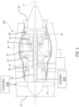
- FIG. 1 an example gas turbine engine 100 of a type preferably provided for use in subsonic flight is illustrated, generally comprising in serial flow communication a fan 12 through which ambient air is propelled, a compressor section 14 for pressurizing the air, a combustor 16 in which the compressed air is mixed with fuel and ignited for generating an annular stream of hot combustion gases, and a turbine section 18 for extracting energy from the combustion gases, which exit via an exhaust 36.
- High-pressure rotor(s) of the turbine section 18 (referred to as “HP turbine rotor(s) 20") are drivingly engaged to high-pressure rotor(s) of the compressor section 14 (referred to as “HP compressor rotor(s) 22") through a high-pressure shaft 24.
- the turbine section 18 includes a vane 19 between the combustor 16 and the HP turbine rotor(s) 20.
- Low-pressure rotor(s) of the turbine section 18 (referred to as “LP turbine rotor(s) 26") are drivingly engaged to the fan rotor 12 and to low-pressure rotor(s) of the compressor section 14 (referred to as “LP compressor rotor(s) 30") through a low-pressure shaft 28 extending within the high-pressure shaft 24 and rotating independently therefrom.
- the gas turbine engine 10 may alternatively be another type of engine, for example a turboshaft engine, also generally comprising in serial flow communication a compressor section, a combustor, and a turbine section, and a fan through which ambient air is propelled.
- a turboprop engine may also apply.
- the engine 10 is described herein for flight applications, it should be understood that other uses, such as industrial or the like, may apply.
- the engine 100 is provided in the form of a multi-spool engine having a high-pressure spool and a low pressure (LP) spool independently rotatable about axis 11.
- LP low pressure
- a multi-spool engine could have more than two spools.
- the embodiments described herein also consider the use of single-spool engines.
- Control of the operation of the engine 100 can be effected by one or more control systems, for example a controller 110, which is communicatively coupled to the engine 100.
- the operation of the engine 100 can be controlled by way of one or more actuators, mechanical linkages, hydraulic systems, and the like.
- the controller 110 can be coupled to the actuators, mechanical linkages, hydraulic systems, and the like, in any suitable fashion for effecting control of the engine 100.
- the controller 110 can modulate the position and orientation of variable geometry mechanisms within the engine 100, the bleed level of the engine 100, and fuel flow, based on predetermined schedules or algorithms.
- the controller 110 includes one or more FADEC(s), electronic engine controller(s) (EEC(s)), or the like, that are programmed to control the operation of the engine 100.
- the controller 110 is configured for monitoring an engine core temperature and comparing it to a thermal limit of the engine.
- the thermal limit is adjusted for a level of deterioration of the engine. In this manner, the thermal limit used for power management of the engine gets corrected over the life of the engine, such that an older engine can output as much power as a new engine.
- the deterioration bias is associated with a level of deterioration of the engine and pushes the adjusted thermal limit higher on older engines to account for a change in performance of the engine over time. Any known or other method of determining a deterioration level of the engine may be used, such as but not limited to testing, simulations, modeling (e.g. state variable model (SVM)), and the like. A corresponding deterioration bias for the level of deterioration as determined is applied to the actual thermal limit to obtain the adjusted thermal limit.
- SVM state variable model
- the deterioration bias corresponds to a difference between a reference engine core temperature and an expected engine core temperature, as exemplified in the diagram of FIG. 2 .
- the reference core temperature 202 is an actual engine core temperature at a given reference condition, and is compared to the expected core temperature 206 at the same reference condition to obtain the deterioration bias 208.
- the expected core temperature 206 may be selected from a plurality of possible expected core temperatures 204, as a function of various parameters such as flight conditions (e.g. altitude, pressure, temperature, etc.), engine power, engine thrust, and the like.
- the expected core temperature 206 is the temperature expected for an engine without deterioration.
- the reference condition may be, for example at take-off, climb, cruise, idle, etc.
- the expected core temperature 206 also corresponds to a core temperature expected for the reference condition, and the possible expected core temperatures 204 may also vary as a function of the reference condition at which the actual core temperature is obtained.
- the actual core temperature is established via an engine power assurance check (EPAC). by using a state variable model, or any various other forms of trend monitoring.
- the reference condition used is a flight take-off condition. During the aircraft's take-off phase of the first flight of the day, engine data upon lift-off is recorded, and comprises the engine core temperature at the take-off phase. The controller 110 may use the aircraft and/or engine parameters at the take-off phase to select the expected core temperature of the engine and compute the deterioration bias accordingly.
- the value of the deterioration bias may be adjusted over time to account for various transient effects, for instance those associated with the setting of engine component clearances. Additionally or alternatively, the value of the deterioration bias may be scaled to take into account the fact that the deterioration recorded at, for instance, a take-off condition may not apply to all conditions across the flight envelope in the same way. For example, the deterioration bias at a take-off condition for an outside temperature of 10 degrees Celsius may be equivalent to the deterioration bias at a max take-off condition for an outside temperature of 14 degrees Celsius. Other scale factors may be contemplated as well.
- the deterioration bias may be confirmed by calculating deterioration bias values at multiple points during the aircraft's flight. For instance, deterioration bias values may be calculated at a take-off condition, during a climbing condition, and at a cruising condition. Other conditions for calculating the deterioration bias may be contemplated as well. A rolling average of recently-calculated deterioration bias values, for instance the ten most-recent deterioration bias values, may be used to limit variations.
- an exemplary method 300 for operating the engine 100 to set the engine's output power may be performed by the controller 110 in part or in whole.
- an engine core temperature is monitored.
- monitoring the engine core temperature comprises measuring the actual core temperature using one or more real or virtual sensing device.
- Example temperature measurement locations of the engine 100 are illustrated in FIG. 4 .
- T0 taken upstream of the inlet 32, refers to an ambient temperature of the environment surrounding the engine 100. Although illustrated here as being captured upstream of the inlet 32, it should be understood that the ambient temperature T0 can be captured at any suitable location in the environment in which the engine 100 is operating.
- T1 refers to an inlet temperature, taken at the inlet 32 of the engine 100, just as the air from the environment enters through the fan rotor 12.
- T2 refers to a low-pressure compressor inlet temperature, taken before the LP turbine rotor(s) 26 of the low-pressure compressor stage 14 1 .
- T2.5 refers to a high-pressure compressor temperature, taken between the ICC 34 and the high-pressure compressor stage 14 2 .
- T3 refers to a high-pressure compressor delivery temperature, taken after the high-pressure compressor stages 14 2 and 14 3 , for instance after the HP compressor rotor(s) 22.
- T4 refers to a combustor outlet temperature, taken before the HP turbine rotor(s) 20, and after the combustor 16.
- T4.1 refers to a temperature taken at or near an entry to the high-pressure turbine 18 2 .
- T4.1 can serve as a proxy for T4 because the exit of the combustor (where T4 is taken) and the entry to the high-pressure turbine 18 2 (where T4.1 is taken) are connected to one another.
- T4.5 refers to a temperature taken between the high-pressure turbine 18 2 and the low-pressure turbine 18 1 .
- T5 refers to the turbine outlet temperature, taken after the LP turbine rotor(s) 26 of the low-pressure turbine 18 1 .
- T6 refers to an exhaust gas temperature, taken between the low-pressure turbine 18 1 and the exhaust 36.
- T8 refers to an exhaust gas temperature, taken at the outlet of the exhaust 36.
- the temperature used for the actual engine core temperature is the maximum temperature of the engine.
- the maximum temperature usually occurs at location T4 or at location T4.1, which may be difficult to measure in at least some engines due to possible instrumentation and material temperature limitations.
- One approach to overcoming such difficulties is deriving the temperature at location T4 based on a temperature measured downstream from location T4, where the temperature is cooler, and where instrumentation and material temperature limitations are lowered.
- One example includes measuring the temperature at location T4.5.
- T4.5 is sometimes referred to as an inter-turbine or indicated turbine temperature (ITT) and in this embodiment is taken between the HP turbine rotor(s) 20 and LP turbine rotor(s) 26.
- a relationship between the temperatures at locations T4 to T4.5, used for deriving the temperature at location T4, can be determined during the development phase of the engine 100.
- the relationship can be provided to the engine controller 110 to derive the T4 temperature as may be required for operation of the engine 100.
- monitoring the engine core temperature comprises estimating or deriving the actual engine core temperature. For example, an iterative method for predicting T4, as described in U.S. Patent Application No. 16/906,637 may be used. Other methods or algorithms for deriving or estimating the engine core temperature may be used.
- the output power of the engine 100 is set in accordance with a reference power based on non-thermal limits of the engine, at step 304.
- non-thermal limits may comprise mechanical limits, for instance based on the speed of fan 12 or gearbox 120, or other engine 100 limits such as gas generator pressure and mechanical or corrected rotor speeds, among others.
- the reference power may be selected as a minimum from a plurality of non-thermal limits. Fixed power schedules may be associated with each non-thermal limit, based on a plurality of engine and aircraft parameters such as altitude, ambient temperature, aircraft speed, and the like.
- the output power of the engine 100 is set to a value lower than the reference power to reduce the engine core temperature, at step 306. Therefore, instead of using a fixed thermal limit to be considered with the mechanical limit and any other limit of the engine to set engine power, engine core temperature is used as a monitoring value in setting the engine power.
- the power management approach also concurrently manages engine temperature, and considers engine deterioration in temperature and power management.
- Step 306 is performed before the core temperature is above the adjusted thermal limit. For example, if a trend of increasing engine core temperature is detected, step 306 may be performed when the engine core temperature is near or approaches the adjusted thermal limit.
- Various triggers may be used to cause step 306 to be performed prior to reaching the adjusted thermal limit.
- a trigger such as a given number (X) of consecutive increases in core temperature and a difference between the core temperature and the adjusted thermal limit of less than a given difference threshold (T diff ) causes the method 300 to move to step 306 before the adjusted thermal limit is reached by the core temperature:
- Engine core temp ⁇ adjusted thermal limit ⁇ T diff AND Consecutive increases X
- the trigger is that the difference between the core temperature and the adjusted thermal limit is less than the difference threshold (T diff ) for a duration greater than a given time threshold (T time ): Engine core temp ⁇ adjusted thermal limit ⁇ T diff AND Duration ⁇ T time
- the trigger is that the difference between the core temperature and the adjusted thermal limit is less than the difference threshold (T diff ) and the last increase in temperature was for a value greater than an increase threshold (T incr ): Engine core temp ⁇ adjusted thermal limit ⁇ T diff AND Last Increase ⁇ T iner
- a prediction algorithm such as those implemented by a proportional-integral (PI) or proportional-integral-derivative (PID) controller, or a machine-learning algorithm, is used to detect a trend or predict a crossing of the adjusted thermal limit by the engine core temperature and trigger step 306 prior to reaching the adjusted thermal limit.
- PI proportional-integral
- PID proportional-integral-derivative
- an exemplary control scheme 500 for setting the output power of the engine 100 is shown.
- non-thermal limits 504, 506 are used to set the output power of the engine 100 in accordance with a reference power
- a thermal limit 502 is used to concurrently monitor an engine core temperature and intervene in power management only in certain circumstances.
- the thermal limit 502 of the engine 100 may take into account, for instance, the engine's current rating (e.g. max takeoff, max continuous) and power lever angle (PLA).
- the thermal limit is then adjusted for the level of deterioration of the engine, for instance by applying the deterioration bias to the actual thermal limit to obtain an adjusted thermal limit.
- the deterioration bias may be determined via the method exemplified in the diagram of FIG. 2 , as discussed above. Other methods for determining the deterioration bias may be contemplated as well.
- Non-thermal limits 504, 506 are used to set the output power of the engine 100 in accordance with a reference power.
- a flat rating i.e. a mechanical limit of the engine 100
- Such mechanical limits may be based on, for instance, the rotational speed of fan 12 or the rotational speed of gearbox 120.
- the flat rating may take into account, for instance, the engine's current rating, PLA and flight condition(s) of the aircraft.
- other engine limits for instance such as gas generator pressure and mechanical or corrected rotor speeds, are determined. Such other engine limits may take into account, for instance, the engine's current rating, PLA and flight condition(s) of the aircraft.
- Fixed power schedules may be associated with each non-thermal limit, based on a plurality of engine and aircraft parameters such as altitude, ambient temperature, aircraft speed, and the like. At 508, a minimum between the flat rating and the other engine limits may be selected and outputted as the reference power.
- steps 302, 304 and 306 of method 300 may be implemented to set the engine's output power.
- Various engine sensors 512 positioned throughout engine 100 may monitor or detect a current engine core temperature. Such sensors may be real or virtual sensing devices, as discussed above. Sensors 512 may also monitor or detect an actual engine output power.
- the engine power output is set to the reference power.
- the engine core temperature is concurrently monitored to ensure that it does not exceed the adjusted thermal limit. If the engine core temperature is near or exceeds the adjusted thermal limit, the output power of the engine 100 is set to a value lower than the reference power to reduce the engine core temperature. In various embodiments, the output power of the engine 100 may be set to a value lower than the reference power until the engine core temperature drops below the engine thermal limit adjusted based on the level of deterioration of the engine 100.
- the controller 110 is implemented with a computing device 600, an example of which is illustrated in Fig. 6 .
- a computing device 600 for simplicity only one computing device 600 is shown but the controller 110 may include more computing devices 600 operable to exchange data.
- the computing devices 600 may be the same or different types of devices.
- the controller 110 can be implemented as part of a full-authority digital engine controls (FADEC) or other similar device, including electronic engine control (EEC), engine control unit (ECU), and the like.
- FADEC full-authority digital engine controls
- EEC electronic engine control
- ECU engine control unit
- the computing device 600 comprises a processing unit 602 and a memory 604 which has stored therein computer-executable instructions 606.
- the processing unit 602 may comprise any suitable devices configured to implement the method 300 such that instructions 606, when executed by the computing device 600 or other programmable apparatus, may cause the functions/acts/steps performed as part of the method 300 as described herein to be executed.
- the processing unit 602 may comprise, for example, any type of general-purpose microprocessor or microcontroller, a digital signal processing (DSP) processor, a central processing unit (CPU), an integrated circuit, a field programmable gate array (FPGA), a reconfigurable processor, other suitably programmed or programmable logic circuits, or any combination thereof.
- DSP digital signal processing
- CPU central processing unit
- FPGA field programmable gate array
- reconfigurable processor other suitably programmed or programmable logic circuits, or any combination thereof.
- the memory 604 may comprise any suitable known or other machine-readable storage medium.
- the memory 604 may comprise non-transitory computer readable storage medium, for example, but not limited to, an electronic, magnetic, optical, electromagnetic, infrared, or semiconductor system, apparatus, or device, or any suitable combination of the foregoing.
- the memory 604 may include a suitable combination of any type of computer memory that is located either internally or externally to device, for example random-access memory (RAM), read-only memory (ROM), compact disc read-only memory (CDROM), electro-optical memory, magnetooptical memory, erasable programmable read-only memory (EPROM), and electrically-erasable programmable read-only memory (EEPROM), Ferroelectric RAM (FRAM) or the like.
- Memory 604 may comprise any storage means (e.g., devices) suitable for retrievably storing machine-readable instructions 606 executable by processing unit 602.
- the methods and systems for operating the engine 100 described herein may be implemented in a high level procedural or object oriented programming or scripting language, or a combination thereof, to communicate with or assist in the operation of a computer system, for example the computing device 600.
- the methods and systems for operating the engine 100 may be implemented in assembly or machine language.
- the language may be a compiled or interpreted language.
- Program code for implementing the methods and systems for operating the engine 100 may be stored on a storage media or a device, for example a ROM, a magnetic disk, an optical disc, a flash drive, or any other suitable storage media or device.
- the program code may be readable by a general or special-purpose programmable computer for configuring and operating the computer when the storage media or device is read by the computer to perform the procedures described herein.
- Embodiments of the methods and systems for operating the engine 100 may also be considered to be implemented by way of a non-transitory computer-readable storage medium having a computer program stored thereon.
- the computer program may comprise computer-readable instructions which cause a computer, or more specifically the processing unit 602 of the computing device 600, to operate in a specific and predefined manner to perform the functions described herein, for example those described in the method 300.
- Computer-executable instructions may be in many forms, including program modules, executed by one or more computers or other devices.
- program modules include routines, programs, objects, components, data structures, etc., that perform particular tasks or implement particular abstract data types.
- functionality of the program modules may be combined or distributed as desired in various embodiments.
- the controller 110 may set the reference power to the flat rated power by default and lower or limit the output power if the engine core temperature crosses the adjusted thermal limit threshold.
- the reference power may be set based on fan speed, nozzle pressure ratio, and other parameters.
Landscapes
- Engineering & Computer Science (AREA)
- Chemical & Material Sciences (AREA)
- Combustion & Propulsion (AREA)
- Aviation & Aerospace Engineering (AREA)
- Mechanical Engineering (AREA)
- General Engineering & Computer Science (AREA)
- Manufacturing & Machinery (AREA)
- Transportation (AREA)
- Control Of Vehicle Engines Or Engines For Specific Uses (AREA)
- Control Of Turbines (AREA)
- Combined Controls Of Internal Combustion Engines (AREA)
Claims (10)
- Procédé de fonctionnement d'un moteur (100), le procédé comprenant :la surveillance d'une température de noyau de moteur ;lorsque la température de noyau de moteur est inférieure à une limite thermique de moteur ajustée pour un niveau de détérioration du moteur (100), le réglage d'une puissance de sortie du moteur (100) conformément à une puissance de référence sur la base des limites non thermiques du moteur (100) ; etlorsqu'un nombre donné (X) d'augmentations consécutives de la température de noyau de moteur est atteint, et qu'une différence entre la température de noyau de moteur et la limite thermique ajustée est inférieure à un seuil de différence donné (Tdiff), le réglage de la puissance de sortie du moteur (100) à une valeur inférieure à la puissance de référence sur la base des limites non thermiques du moteur (100) pour réduire la température de noyau de moteur.
- Procédé de fonctionnement d'un moteur (100), le procédé comprenant :la surveillance d'une température de noyau de moteur ;lorsque la température de noyau de moteur est inférieure à une limite thermique de moteur ajustée pour un niveau de détérioration du moteur (100), le réglage d'une puissance de sortie du moteur (100) conformément à une puissance de référence sur la base des limites non thermiques du moteur (100) ; etlorsque la différence entre la température de noyau de moteur et la limite thermique ajustée est inférieure à un seuil de différence (Tdiff) pendant une durée supérieure à un seuil de temps donné (Ttemps), le réglage de la puissance de sortie du moteur (100) à une valeur inférieure à la puissance de référence sur la base des limites non thermiques du moteur (100) pour réduire la température de noyau de moteur.
- Procédé de fonctionnement d'un moteur (100), le procédé comprenant :la surveillance d'une température de noyau de moteur ;lorsque la température de noyau de moteur est inférieure à une limite thermique de moteur ajustée pour un niveau de détérioration du moteur (100), le réglage d'une puissance de sortie du moteur (100) conformément à une puissance de référence sur la base des limites non thermiques du moteur (100) ; etlorsque la différence entre la température de noyau de moteur et la limite thermique ajustée est inférieure à un seuil de différence (Tdiff), et qu'une dernière augmentation en température était pour une valeur supérieure à un seuil d'augmentation (Tincr), le réglage de la puissance de sortie du moteur (100) à une valeur inférieure à la puissance de référence sur la base des limites non thermiques du moteur (100) pour réduire la température de noyau de moteur.
- Procédé de fonctionnement d'un moteur (100), le procédé comprenant :la surveillance d'une température de noyau de moteur ;lorsque la température de noyau de moteur est inférieure à une limite thermique de moteur ajustée pour un niveau de détérioration du moteur (100), le réglage d'une puissance de sortie du moteur (100) conformément à une puissance de référence sur la base des limites non thermiques du moteur (100) ; etlorsqu'un algorithme de prédiction ou un algorithme d'apprentissage automatique détecte une tendance ou prédit un dépassement de la limite thermique ajustée par la température de noyau de moteur, le réglage de la puissance de sortie du moteur (100) à une valeur inférieure à la puissance de référence sur la base des limites non thermiques du moteur (100) pour réduire la température de noyau de moteur.
- Procédé selon une quelconque revendication précédente, dans lequel le réglage de la puissance de sortie du moteur (100) conformément à la puissance de référence sur la base des limites non thermiques du moteur (100) comprend la sélection d'un minimum entre une puissance de sortie sur la base d'une limite mécanique de moteur et une puissance de sortie sur la base d'une limite supplémentaire de moteur.
- Procédé selon une quelconque revendication précédente, dans lequel la surveillance de la température de noyau de moteur comprend l'établissement du niveau de détérioration du moteur (100) sur la base d'une condition de référence du moteur (100).
- Procédé selon la revendication 6, dans lequel le moteur (100) est un moteur d'aéronef et la condition de référence du moteur (100) est une condition de décollage.
- Procédé selon la revendication 7, dans lequel l'établissement du niveau de détérioration du moteur (100) sur la base d'une condition de référence du moteur (100) comprend :pendant une phase de décollage, l'enregistrement d'une valeur de décollage pour une température de noyau de moteur ; etle calcul du niveau de détérioration du moteur (100) en comparant la valeur de décollage pour la température de noyau de moteur à une valeur de décollage attendue pour une température de noyau de moteur d'un nouveau moteur (100) sans détérioration dans une même condition de vol.
- Procédé selon l'une quelconque des revendications 6 à 8, dans lequel l'établissement du niveau de détérioration du moteur (100) sur la base d'une condition de référence du moteur (100) comprend la prise en compte d'un changement de performance du moteur (100) au fil du temps.
- Système comprenant un contrôleur (110) configuré pour être couplé de manière communicative à un moteur à turbine à gaz (100), le contrôleur comprenant :un processeur (602) ; etun support non transitoire lisible par ordinateur (604) sur lequel sont stockées des instructions de programme (606) exécutables par le processeur (602) pour réaliser les étapes définies selon une quelconque revendication précédente.
Applications Claiming Priority (1)
| Application Number | Priority Date | Filing Date | Title |
|---|---|---|---|
| US17/468,906 US11628945B2 (en) | 2021-09-08 | 2021-09-08 | Output power management for engines |
Publications (2)
| Publication Number | Publication Date |
|---|---|
| EP4148256A1 EP4148256A1 (fr) | 2023-03-15 |
| EP4148256B1 true EP4148256B1 (fr) | 2025-05-21 |
Family
ID=83270964
Family Applications (1)
| Application Number | Title | Priority Date | Filing Date |
|---|---|---|---|
| EP22194693.2A Active EP4148256B1 (fr) | 2021-09-08 | 2022-09-08 | Gestion de puissance de sortie pour moteurs |
Country Status (3)
| Country | Link |
|---|---|
| US (1) | US11628945B2 (fr) |
| EP (1) | EP4148256B1 (fr) |
| CA (1) | CA3171059A1 (fr) |
Families Citing this family (1)
| Publication number | Priority date | Publication date | Assignee | Title |
|---|---|---|---|---|
| CN120491713B (zh) * | 2025-05-20 | 2026-02-17 | 国电投河南工程运维有限公司 | 燃气发电机组温度测量控制方法以及系统 |
Family Cites Families (9)
| Publication number | Priority date | Publication date | Assignee | Title |
|---|---|---|---|---|
| US20070214795A1 (en) * | 2006-03-15 | 2007-09-20 | Paul Cooker | Continuous real time EGT margin control |
| GB0722398D0 (en) | 2007-11-15 | 2007-12-27 | Rolls Royce Plc | A method of monitoring a gas turbine engine |
| JP5356967B2 (ja) * | 2009-09-29 | 2013-12-04 | 本田技研工業株式会社 | 航空機用ガスタービン・エンジン |
| CN102928232B (zh) * | 2012-11-21 | 2015-01-21 | 中国民用航空飞行学院 | 一种航空发动机整机性能衰退趋势预测方法 |
| US20170175646A1 (en) * | 2015-12-22 | 2017-06-22 | General Electric Company | Method and system for stall margin modulation as a function of engine health |
| US10442544B2 (en) | 2016-05-09 | 2019-10-15 | Rolls-Royce North American Technologies, Inc. | Engine degradation management via multi-engine mechanical power control |
| US20180320598A1 (en) * | 2017-05-02 | 2018-11-08 | Pratt & Whitney Canada Corp. | Method and system for detecting and accommodating loss of a torque signal |
| US11286855B2 (en) * | 2019-03-15 | 2022-03-29 | General Electric Company | Systems and methods for operating a turbine engine |
| US11536205B2 (en) * | 2020-03-31 | 2022-12-27 | Rolls-Royce Plc | Gas turbine engine operating schedules for optimizing ceramic matrix composite component life |
-
2021
- 2021-09-08 US US17/468,906 patent/US11628945B2/en active Active
-
2022
- 2022-08-24 CA CA3171059A patent/CA3171059A1/fr active Pending
- 2022-09-08 EP EP22194693.2A patent/EP4148256B1/fr active Active
Also Published As
| Publication number | Publication date |
|---|---|
| US11628945B2 (en) | 2023-04-18 |
| CA3171059A1 (fr) | 2023-03-08 |
| US20230070587A1 (en) | 2023-03-09 |
| EP4148256A1 (fr) | 2023-03-15 |
Similar Documents
| Publication | Publication Date | Title |
|---|---|---|
| US6272422B2 (en) | Method and apparatus for use in control of clearances in a gas turbine engine | |
| US11486310B2 (en) | System and method for dynamic engine motoring | |
| EP3712074B1 (fr) | Procédé et système pour régler la puissance d'un moteur d'avion | |
| EP3401530B1 (fr) | Procédé et système de réglage d'un programme d'accélération pour un démarrage de moteur | |
| US20230102382A1 (en) | Method and system for determining an engine temperature | |
| CN105392977B (zh) | 用于生成要注入涡轮引擎的燃烧室的燃料流的命令的方法和设备 | |
| EP3835559A1 (fr) | Système et procédé pour détecter et gérer une perte du signal de couple sur un moteur à turbine à gaz | |
| EP3409926B1 (fr) | Procédé et système de détection d'une température élevée d'une turbine à gaz | |
| EP4148256B1 (fr) | Gestion de puissance de sortie pour moteurs | |
| EP4119775B1 (fr) | Système et procédé actif de commande de jeu pour moteur d'avion | |
| EP3623608B1 (fr) | Procédé et système de réglage d'un mécanisme à géométrie variable | |
| EP4141241A1 (fr) | Procédé et système de fonctionnement d'un moteur pour générer une poussée supplémentaire | |
| EP4105470B1 (fr) | Procédé et système de fonctionnement d'un moteur pour empêcher le pompage à haute puissance | |
| EP4134538B1 (fr) | Procédés et systèmes de fonctionnement d'un moteur pour générer une poussée supplémentaire |
Legal Events
| Date | Code | Title | Description |
|---|---|---|---|
| PUAI | Public reference made under article 153(3) epc to a published international application that has entered the european phase |
Free format text: ORIGINAL CODE: 0009012 |
|
| STAA | Information on the status of an ep patent application or granted ep patent |
Free format text: STATUS: THE APPLICATION HAS BEEN PUBLISHED |
|
| AK | Designated contracting states |
Kind code of ref document: A1 Designated state(s): AL AT BE BG CH CY CZ DE DK EE ES FI FR GB GR HR HU IE IS IT LI LT LU LV MC MK MT NL NO PL PT RO RS SE SI SK SM TR |
|
| STAA | Information on the status of an ep patent application or granted ep patent |
Free format text: STATUS: REQUEST FOR EXAMINATION WAS MADE |
|
| 17P | Request for examination filed |
Effective date: 20230915 |
|
| RBV | Designated contracting states (corrected) |
Designated state(s): AL AT BE BG CH CY CZ DE DK EE ES FI FR GB GR HR HU IE IS IT LI LT LU LV MC MK MT NL NO PL PT RO RS SE SI SK SM TR |
|
| GRAP | Despatch of communication of intention to grant a patent |
Free format text: ORIGINAL CODE: EPIDOSNIGR1 |
|
| STAA | Information on the status of an ep patent application or granted ep patent |
Free format text: STATUS: GRANT OF PATENT IS INTENDED |
|
| RIC1 | Information provided on ipc code assigned before grant |
Ipc: F02C 9/28 20060101AFI20241127BHEP |
|
| INTG | Intention to grant announced |
Effective date: 20241213 |
|
| GRAS | Grant fee paid |
Free format text: ORIGINAL CODE: EPIDOSNIGR3 |
|
| GRAA | (expected) grant |
Free format text: ORIGINAL CODE: 0009210 |
|
| STAA | Information on the status of an ep patent application or granted ep patent |
Free format text: STATUS: THE PATENT HAS BEEN GRANTED |
|
| AK | Designated contracting states |
Kind code of ref document: B1 Designated state(s): AL AT BE BG CH CY CZ DE DK EE ES FI FR GB GR HR HU IE IS IT LI LT LU LV MC MK MT NL NO PL PT RO RS SE SI SK SM TR |
|
| REG | Reference to a national code |
Ref country code: GB Ref legal event code: FG4D |
|
| REG | Reference to a national code |
Ref country code: CH Ref legal event code: EP |
|
| REG | Reference to a national code |
Ref country code: DE Ref legal event code: R096 Ref document number: 602022014894 Country of ref document: DE |
|
| REG | Reference to a national code |
Ref country code: IE Ref legal event code: FG4D |
|
| REG | Reference to a national code |
Ref country code: NL Ref legal event code: MP Effective date: 20250521 |
|
| PG25 | Lapsed in a contracting state [announced via postgrant information from national office to epo] |
Ref country code: FI Free format text: LAPSE BECAUSE OF FAILURE TO SUBMIT A TRANSLATION OF THE DESCRIPTION OR TO PAY THE FEE WITHIN THE PRESCRIBED TIME-LIMIT Effective date: 20250521 Ref country code: ES Free format text: LAPSE BECAUSE OF FAILURE TO SUBMIT A TRANSLATION OF THE DESCRIPTION OR TO PAY THE FEE WITHIN THE PRESCRIBED TIME-LIMIT Effective date: 20250521 Ref country code: PT Free format text: LAPSE BECAUSE OF FAILURE TO SUBMIT A TRANSLATION OF THE DESCRIPTION OR TO PAY THE FEE WITHIN THE PRESCRIBED TIME-LIMIT Effective date: 20250922 |
|
| PGFP | Annual fee paid to national office [announced via postgrant information from national office to epo] |
Ref country code: DE Payment date: 20250820 Year of fee payment: 4 |
|
| REG | Reference to a national code |
Ref country code: LT Ref legal event code: MG9D |
|
| PG25 | Lapsed in a contracting state [announced via postgrant information from national office to epo] |
Ref country code: NO Free format text: LAPSE BECAUSE OF FAILURE TO SUBMIT A TRANSLATION OF THE DESCRIPTION OR TO PAY THE FEE WITHIN THE PRESCRIBED TIME-LIMIT Effective date: 20250821 Ref country code: GR Free format text: LAPSE BECAUSE OF FAILURE TO SUBMIT A TRANSLATION OF THE DESCRIPTION OR TO PAY THE FEE WITHIN THE PRESCRIBED TIME-LIMIT Effective date: 20250822 |
|
| PG25 | Lapsed in a contracting state [announced via postgrant information from national office to epo] |
Ref country code: NL Free format text: LAPSE BECAUSE OF FAILURE TO SUBMIT A TRANSLATION OF THE DESCRIPTION OR TO PAY THE FEE WITHIN THE PRESCRIBED TIME-LIMIT Effective date: 20250521 Ref country code: PL Free format text: LAPSE BECAUSE OF FAILURE TO SUBMIT A TRANSLATION OF THE DESCRIPTION OR TO PAY THE FEE WITHIN THE PRESCRIBED TIME-LIMIT Effective date: 20250521 |
|
| PG25 | Lapsed in a contracting state [announced via postgrant information from national office to epo] |
Ref country code: BG Free format text: LAPSE BECAUSE OF FAILURE TO SUBMIT A TRANSLATION OF THE DESCRIPTION OR TO PAY THE FEE WITHIN THE PRESCRIBED TIME-LIMIT Effective date: 20250521 |
|
| PG25 | Lapsed in a contracting state [announced via postgrant information from national office to epo] |
Ref country code: HR Free format text: LAPSE BECAUSE OF FAILURE TO SUBMIT A TRANSLATION OF THE DESCRIPTION OR TO PAY THE FEE WITHIN THE PRESCRIBED TIME-LIMIT Effective date: 20250521 |
|
| PGFP | Annual fee paid to national office [announced via postgrant information from national office to epo] |
Ref country code: FR Payment date: 20250820 Year of fee payment: 4 |
|
| PG25 | Lapsed in a contracting state [announced via postgrant information from national office to epo] |
Ref country code: RS Free format text: LAPSE BECAUSE OF FAILURE TO SUBMIT A TRANSLATION OF THE DESCRIPTION OR TO PAY THE FEE WITHIN THE PRESCRIBED TIME-LIMIT Effective date: 20250821 |
|
| PG25 | Lapsed in a contracting state [announced via postgrant information from national office to epo] |
Ref country code: IS Free format text: LAPSE BECAUSE OF FAILURE TO SUBMIT A TRANSLATION OF THE DESCRIPTION OR TO PAY THE FEE WITHIN THE PRESCRIBED TIME-LIMIT Effective date: 20250921 |
|
| PG25 | Lapsed in a contracting state [announced via postgrant information from national office to epo] |
Ref country code: LV Free format text: LAPSE BECAUSE OF FAILURE TO SUBMIT A TRANSLATION OF THE DESCRIPTION OR TO PAY THE FEE WITHIN THE PRESCRIBED TIME-LIMIT Effective date: 20250521 |
|
| REG | Reference to a national code |
Ref country code: AT Ref legal event code: MK05 Ref document number: 1796935 Country of ref document: AT Kind code of ref document: T Effective date: 20250521 |
|
| PG25 | Lapsed in a contracting state [announced via postgrant information from national office to epo] |
Ref country code: DK Free format text: LAPSE BECAUSE OF FAILURE TO SUBMIT A TRANSLATION OF THE DESCRIPTION OR TO PAY THE FEE WITHIN THE PRESCRIBED TIME-LIMIT Effective date: 20250521 Ref country code: AT Free format text: LAPSE BECAUSE OF FAILURE TO SUBMIT A TRANSLATION OF THE DESCRIPTION OR TO PAY THE FEE WITHIN THE PRESCRIBED TIME-LIMIT Effective date: 20250521 Ref country code: SM Free format text: LAPSE BECAUSE OF FAILURE TO SUBMIT A TRANSLATION OF THE DESCRIPTION OR TO PAY THE FEE WITHIN THE PRESCRIBED TIME-LIMIT Effective date: 20250521 |
|
| PG25 | Lapsed in a contracting state [announced via postgrant information from national office to epo] |
Ref country code: CZ Free format text: LAPSE BECAUSE OF FAILURE TO SUBMIT A TRANSLATION OF THE DESCRIPTION OR TO PAY THE FEE WITHIN THE PRESCRIBED TIME-LIMIT Effective date: 20250521 |
|
| PG25 | Lapsed in a contracting state [announced via postgrant information from national office to epo] |
Ref country code: EE Free format text: LAPSE BECAUSE OF FAILURE TO SUBMIT A TRANSLATION OF THE DESCRIPTION OR TO PAY THE FEE WITHIN THE PRESCRIBED TIME-LIMIT Effective date: 20250521 |
|
| PG25 | Lapsed in a contracting state [announced via postgrant information from national office to epo] |
Ref country code: SK Free format text: LAPSE BECAUSE OF FAILURE TO SUBMIT A TRANSLATION OF THE DESCRIPTION OR TO PAY THE FEE WITHIN THE PRESCRIBED TIME-LIMIT Effective date: 20250521 |
|
| PG25 | Lapsed in a contracting state [announced via postgrant information from national office to epo] |
Ref country code: IT Free format text: LAPSE BECAUSE OF FAILURE TO SUBMIT A TRANSLATION OF THE DESCRIPTION OR TO PAY THE FEE WITHIN THE PRESCRIBED TIME-LIMIT Effective date: 20250521 |
|
| PG25 | Lapsed in a contracting state [announced via postgrant information from national office to epo] |
Ref country code: RO Free format text: LAPSE BECAUSE OF FAILURE TO SUBMIT A TRANSLATION OF THE DESCRIPTION OR TO PAY THE FEE WITHIN THE PRESCRIBED TIME-LIMIT Effective date: 20250521 |
|
| REG | Reference to a national code |
Ref country code: DE Ref legal event code: R097 Ref document number: 602022014894 Country of ref document: DE |
|
| PLBE | No opposition filed within time limit |
Free format text: ORIGINAL CODE: 0009261 |
|
| STAA | Information on the status of an ep patent application or granted ep patent |
Free format text: STATUS: NO OPPOSITION FILED WITHIN TIME LIMIT |
|
| REG | Reference to a national code |
Ref country code: CH Ref legal event code: L10 Free format text: ST27 STATUS EVENT CODE: U-0-0-L10-L00 (AS PROVIDED BY THE NATIONAL OFFICE) Effective date: 20260402 |
|
| 26N | No opposition filed |
Effective date: 20260224 |