EP4148268A1 - Unité de générateur éolien flottante - Google Patents
Unité de générateur éolien flottante Download PDFInfo
- Publication number
- EP4148268A1 EP4148268A1 EP21876872.9A EP21876872A EP4148268A1 EP 4148268 A1 EP4148268 A1 EP 4148268A1 EP 21876872 A EP21876872 A EP 21876872A EP 4148268 A1 EP4148268 A1 EP 4148268A1
- Authority
- EP
- European Patent Office
- Prior art keywords
- floating
- board
- wind
- sub
- arm
- Prior art date
- Legal status (The legal status is an assumption and is not a legal conclusion. Google has not performed a legal analysis and makes no representation as to the accuracy of the status listed.)
- Withdrawn
Links
Images


Classifications
-
- B—PERFORMING OPERATIONS; TRANSPORTING
- B63—SHIPS OR OTHER WATERBORNE VESSELS; RELATED EQUIPMENT
- B63B—SHIPS OR OTHER WATERBORNE VESSELS; EQUIPMENT FOR SHIPPING
- B63B1/00—Hydrodynamic or hydrostatic features of hulls or of hydrofoils
- B63B1/32—Other means for varying the inherent hydrodynamic characteristics of hulls
- B63B1/322—Other means for varying the inherent hydrodynamic characteristics of hulls using aerodynamic elements, e.g. aerofoils producing a lifting force
-
- B—PERFORMING OPERATIONS; TRANSPORTING
- B63—SHIPS OR OTHER WATERBORNE VESSELS; RELATED EQUIPMENT
- B63B—SHIPS OR OTHER WATERBORNE VESSELS; EQUIPMENT FOR SHIPPING
- B63B35/00—Vessels or similar floating structures specially adapted for specific purposes and not otherwise provided for
- B63B35/44—Floating buildings, stores, drilling platforms, or workshops, e.g. carrying water-oil separating devices
-
- F—MECHANICAL ENGINEERING; LIGHTING; HEATING; WEAPONS; BLASTING
- F03—MACHINES OR ENGINES FOR LIQUIDS; WIND, SPRING, OR WEIGHT MOTORS; PRODUCING MECHANICAL POWER OR A REACTIVE PROPULSIVE THRUST, NOT OTHERWISE PROVIDED FOR
- F03D—WIND MOTORS
- F03D1/00—Wind motors with rotation axis substantially parallel to the air flow entering the rotor
- F03D1/02—Wind motors with rotation axis substantially parallel to the air flow entering the rotor having a plurality of rotors
-
- F—MECHANICAL ENGINEERING; LIGHTING; HEATING; WEAPONS; BLASTING
- F03—MACHINES OR ENGINES FOR LIQUIDS; WIND, SPRING, OR WEIGHT MOTORS; PRODUCING MECHANICAL POWER OR A REACTIVE PROPULSIVE THRUST, NOT OTHERWISE PROVIDED FOR
- F03D—WIND MOTORS
- F03D1/00—Wind motors with rotation axis substantially parallel to the air flow entering the rotor
- F03D1/04—Wind motors with rotation axis substantially parallel to the air flow entering the rotor having stationary wind-guiding means, e.g. with shrouds or channels
-
- F—MECHANICAL ENGINEERING; LIGHTING; HEATING; WEAPONS; BLASTING
- F03—MACHINES OR ENGINES FOR LIQUIDS; WIND, SPRING, OR WEIGHT MOTORS; PRODUCING MECHANICAL POWER OR A REACTIVE PROPULSIVE THRUST, NOT OTHERWISE PROVIDED FOR
- F03D—WIND MOTORS
- F03D13/00—Assembly, mounting or commissioning of wind motors; Arrangements specially adapted for transporting wind motor components
- F03D13/20—Arrangements for mounting or supporting wind motors; Masts or towers for wind motors
- F03D13/22—Foundations specially adapted for wind motors
-
- F—MECHANICAL ENGINEERING; LIGHTING; HEATING; WEAPONS; BLASTING
- F03—MACHINES OR ENGINES FOR LIQUIDS; WIND, SPRING, OR WEIGHT MOTORS; PRODUCING MECHANICAL POWER OR A REACTIVE PROPULSIVE THRUST, NOT OTHERWISE PROVIDED FOR
- F03D—WIND MOTORS
- F03D13/00—Assembly, mounting or commissioning of wind motors; Arrangements specially adapted for transporting wind motor components
- F03D13/20—Arrangements for mounting or supporting wind motors; Masts or towers for wind motors
- F03D13/25—Arrangements for mounting or supporting wind motors; Masts or towers for wind motors specially adapted for offshore installation
-
- F—MECHANICAL ENGINEERING; LIGHTING; HEATING; WEAPONS; BLASTING
- F03—MACHINES OR ENGINES FOR LIQUIDS; WIND, SPRING, OR WEIGHT MOTORS; PRODUCING MECHANICAL POWER OR A REACTIVE PROPULSIVE THRUST, NOT OTHERWISE PROVIDED FOR
- F03D—WIND MOTORS
- F03D7/00—Controlling wind motors
- F03D7/02—Controlling wind motors the wind motors having rotation axis substantially parallel to the air flow entering the rotor
- F03D7/0204—Controlling wind motors the wind motors having rotation axis substantially parallel to the air flow entering the rotor for orientation in relation to wind direction
-
- F—MECHANICAL ENGINEERING; LIGHTING; HEATING; WEAPONS; BLASTING
- F03—MACHINES OR ENGINES FOR LIQUIDS; WIND, SPRING, OR WEIGHT MOTORS; PRODUCING MECHANICAL POWER OR A REACTIVE PROPULSIVE THRUST, NOT OTHERWISE PROVIDED FOR
- F03D—WIND MOTORS
- F03D7/00—Controlling wind motors
- F03D7/02—Controlling wind motors the wind motors having rotation axis substantially parallel to the air flow entering the rotor
- F03D7/0264—Controlling wind motors the wind motors having rotation axis substantially parallel to the air flow entering the rotor for stopping; controlling in emergency situations
- F03D7/0268—Parking or storm protection
-
- F—MECHANICAL ENGINEERING; LIGHTING; HEATING; WEAPONS; BLASTING
- F03—MACHINES OR ENGINES FOR LIQUIDS; WIND, SPRING, OR WEIGHT MOTORS; PRODUCING MECHANICAL POWER OR A REACTIVE PROPULSIVE THRUST, NOT OTHERWISE PROVIDED FOR
- F03D—WIND MOTORS
- F03D7/00—Controlling wind motors
- F03D7/02—Controlling wind motors the wind motors having rotation axis substantially parallel to the air flow entering the rotor
- F03D7/0276—Controlling wind motors the wind motors having rotation axis substantially parallel to the air flow entering the rotor controlling rotor speed, e.g. variable speed
-
- F—MECHANICAL ENGINEERING; LIGHTING; HEATING; WEAPONS; BLASTING
- F03—MACHINES OR ENGINES FOR LIQUIDS; WIND, SPRING, OR WEIGHT MOTORS; PRODUCING MECHANICAL POWER OR A REACTIVE PROPULSIVE THRUST, NOT OTHERWISE PROVIDED FOR
- F03D—WIND MOTORS
- F03D7/00—Controlling wind motors
- F03D7/02—Controlling wind motors the wind motors having rotation axis substantially parallel to the air flow entering the rotor
- F03D7/028—Controlling wind motors the wind motors having rotation axis substantially parallel to the air flow entering the rotor controlling wind motor output power
- F03D7/0288—Controlling wind motors the wind motors having rotation axis substantially parallel to the air flow entering the rotor controlling wind motor output power in relation to clearance between the blade and the tower, i.e. preventing tower strike
-
- B—PERFORMING OPERATIONS; TRANSPORTING
- B63—SHIPS OR OTHER WATERBORNE VESSELS; RELATED EQUIPMENT
- B63B—SHIPS OR OTHER WATERBORNE VESSELS; EQUIPMENT FOR SHIPPING
- B63B35/00—Vessels or similar floating structures specially adapted for specific purposes and not otherwise provided for
- B63B35/44—Floating buildings, stores, drilling platforms, or workshops, e.g. carrying water-oil separating devices
- B63B2035/4433—Floating structures carrying electric power plants
- B63B2035/446—Floating structures carrying electric power plants for converting wind energy into electric energy
-
- F—MECHANICAL ENGINEERING; LIGHTING; HEATING; WEAPONS; BLASTING
- F05—INDEXING SCHEMES RELATING TO ENGINES OR PUMPS IN VARIOUS SUBCLASSES OF CLASSES F01-F04
- F05B—INDEXING SCHEME RELATING TO WIND, SPRING, WEIGHT, INERTIA OR LIKE MOTORS, TO MACHINES OR ENGINES FOR LIQUIDS COVERED BY SUBCLASSES F03B, F03D AND F03G
- F05B2240/00—Components
- F05B2240/10—Stators
- F05B2240/12—Fluid guiding means, e.g. vanes
-
- F—MECHANICAL ENGINEERING; LIGHTING; HEATING; WEAPONS; BLASTING
- F05—INDEXING SCHEMES RELATING TO ENGINES OR PUMPS IN VARIOUS SUBCLASSES OF CLASSES F01-F04
- F05B—INDEXING SCHEME RELATING TO WIND, SPRING, WEIGHT, INERTIA OR LIKE MOTORS, TO MACHINES OR ENGINES FOR LIQUIDS COVERED BY SUBCLASSES F03B, F03D AND F03G
- F05B2240/00—Components
- F05B2240/20—Rotors
- F05B2240/21—Rotors for wind turbines
- F05B2240/221—Rotors for wind turbines with horizontal axis
- F05B2240/2213—Rotors for wind turbines with horizontal axis and with the rotor downwind from the yaw pivot axis
-
- F—MECHANICAL ENGINEERING; LIGHTING; HEATING; WEAPONS; BLASTING
- F05—INDEXING SCHEMES RELATING TO ENGINES OR PUMPS IN VARIOUS SUBCLASSES OF CLASSES F01-F04
- F05B—INDEXING SCHEME RELATING TO WIND, SPRING, WEIGHT, INERTIA OR LIKE MOTORS, TO MACHINES OR ENGINES FOR LIQUIDS COVERED BY SUBCLASSES F03B, F03D AND F03G
- F05B2240/00—Components
- F05B2240/90—Mounting on supporting structures or systems
- F05B2240/93—Mounting on supporting structures or systems on a structure floating on a liquid surface
- F05B2240/932—Mounting on supporting structures or systems on a structure floating on a liquid surface which is a catamaran-like structure
-
- F—MECHANICAL ENGINEERING; LIGHTING; HEATING; WEAPONS; BLASTING
- F05—INDEXING SCHEMES RELATING TO ENGINES OR PUMPS IN VARIOUS SUBCLASSES OF CLASSES F01-F04
- F05B—INDEXING SCHEME RELATING TO WIND, SPRING, WEIGHT, INERTIA OR LIKE MOTORS, TO MACHINES OR ENGINES FOR LIQUIDS COVERED BY SUBCLASSES F03B, F03D AND F03G
- F05B2240/00—Components
- F05B2240/90—Mounting on supporting structures or systems
- F05B2240/95—Mounting on supporting structures or systems offshore
-
- Y—GENERAL TAGGING OF NEW TECHNOLOGICAL DEVELOPMENTS; GENERAL TAGGING OF CROSS-SECTIONAL TECHNOLOGIES SPANNING OVER SEVERAL SECTIONS OF THE IPC; TECHNICAL SUBJECTS COVERED BY FORMER USPC CROSS-REFERENCE ART COLLECTIONS [XRACs] AND DIGESTS
- Y02—TECHNOLOGIES OR APPLICATIONS FOR MITIGATION OR ADAPTATION AGAINST CLIMATE CHANGE
- Y02E—REDUCTION OF GREENHOUSE GAS [GHG] EMISSIONS, RELATED TO ENERGY GENERATION, TRANSMISSION OR DISTRIBUTION
- Y02E10/00—Energy generation through renewable energy sources
- Y02E10/70—Wind energy
- Y02E10/72—Wind turbines with rotation axis in wind direction
-
- Y—GENERAL TAGGING OF NEW TECHNOLOGICAL DEVELOPMENTS; GENERAL TAGGING OF CROSS-SECTIONAL TECHNOLOGIES SPANNING OVER SEVERAL SECTIONS OF THE IPC; TECHNICAL SUBJECTS COVERED BY FORMER USPC CROSS-REFERENCE ART COLLECTIONS [XRACs] AND DIGESTS
- Y02—TECHNOLOGIES OR APPLICATIONS FOR MITIGATION OR ADAPTATION AGAINST CLIMATE CHANGE
- Y02E—REDUCTION OF GREENHOUSE GAS [GHG] EMISSIONS, RELATED TO ENERGY GENERATION, TRANSMISSION OR DISTRIBUTION
- Y02E10/00—Energy generation through renewable energy sources
- Y02E10/70—Wind energy
- Y02E10/727—Offshore wind turbines
-
- Y—GENERAL TAGGING OF NEW TECHNOLOGICAL DEVELOPMENTS; GENERAL TAGGING OF CROSS-SECTIONAL TECHNOLOGIES SPANNING OVER SEVERAL SECTIONS OF THE IPC; TECHNICAL SUBJECTS COVERED BY FORMER USPC CROSS-REFERENCE ART COLLECTIONS [XRACs] AND DIGESTS
- Y02—TECHNOLOGIES OR APPLICATIONS FOR MITIGATION OR ADAPTATION AGAINST CLIMATE CHANGE
- Y02E—REDUCTION OF GREENHOUSE GAS [GHG] EMISSIONS, RELATED TO ENERGY GENERATION, TRANSMISSION OR DISTRIBUTION
- Y02E10/00—Energy generation through renewable energy sources
- Y02E10/70—Wind energy
- Y02E10/728—Onshore wind turbines
Definitions
- the present disclosure relates to a field of wind power generation, in particular to a floating wind turbine.
- Conventional wind turbine structure is a single rotor active yaw system, and an efficiency of wind energy capture is low.
- the fixed foundation occupies a small area and cannot support an installation of a large wind guiding structure.
- the purpose of the present disclosure is to provide a floating wind turbine with a wind guiding structure in order to overcome above shortcomings of the prior art.
- a floating wind turbine includes: a wind deflector, a floating board, an angle adjustment mechanism, a floating foundation, and a tower, wherein the floating foundation is provided with a mounting position, the tower is mounted to the mounting position and the tower is provided with a wind rotor, the floating board is substantially horizontally mounted to the floating foundation, the wind deflector is hinged to the floating board, an opening between the wind deflector and the floating board faces the tower, and the angle adjustment mechanism is operably connected to the wind deflector to adjust an angle between the wind deflector and the floating board.
- the wind deflector includes two or more sub-boards, and each of the sub-boards is hinged to the floating board, the angle adjustment mechanism includes two or more sub-angle adjustment mechanisms, and each of the sub-boards is operably connected to the corresponding sub-angle adjustment mechanism.
- the tower is an airfoil tower
- the airfoil tower includes a support arm, a first airfoil arm and a second airfoil arm provided at an upper end of the support arm, a lower end of the support arm is mounted on the mounting position
- the wind rotor includes a first wind rotor provided on the first airfoil arm and a second wind rotor provided on the second airfoil arm
- the wind deflector includes a first sub-board and a second sub-board, the first sub-board and the second sub-board are respectively hinged to the floating board, the first sub-board corresponds to the first wind rotor, the second sub-board corresponds to the second wind rotor
- the angle adjustment mechanism includes a first sub-angle adjustment mechanism and a second sub-angle adjustment mechanism, the first sub-angle adjustment mechanism is operably connected to the first sub-board to adjust the angle between the first sub-board and the floating board, the second sub-angle adjustment mechanism is operably connected to the second sub-board to adjust
- the floating foundation includes a first floating arm, a second floating arm, and a third floating arm that are connected in a Y shape, a length of the first floating arm is greater than that of the second floating arm or the third floating arm, the mounting position is provided at a joint of the first floating arm, the second floating arm, and the third floating arm, the tower is mounted on the mounting position obliquely.
- the floating board is mounted to the first floating arm, the floating board is arranged symmetrically with respect to the first floating arm such that the floating board includes a first floating board area located on one side of the first floating arm and a second floating board area located on the other side of the first floating arm, the first sub-board is hinged to the first floating board area through a first hinge shaft, and the second sub-board is hinged to the second floating board area through a second hinge shaft.
- first hinge shaft and the second hinge shaft are coaxially arranged.
- the floating wind further includes at least one first buoy mounted below the floating board.
- the floating board includes a plurality of flat boards arranged uniformly and coplanarly.
- the angle between the wind deflector and the floating board is in a range from 10° to 50°.
- the angle adjustment mechanism is mounted between the floating board and the wind deflector
- the angle adjustment mechanism includes a hydraulic cylinder, a base, a connecting block, a first support rod, and a second support rod
- the base is mounted to a hinge shaft between the wind deflector and the floating board
- the hydraulic cylinder is mounted to the base
- a telescopic rod of the hydraulic cylinder faces the tower
- the connecting block is mounted to the telescopic rod of the hydraulic cylinder
- both ends of the first support rod are hinged to the connecting block and the floating board, respectively
- both ends of the second support rod are hinged to the connecting block and wind deflector, respectively.
- a plurality of the hydraulic cylinders, the connecting blocks, the first support rods, and the second support rods are provided, the plurality of hydraulic cylinders are connected in sequence, the connecting block is fixed to the telescopic rod of each hydraulic cylinder, each of the connecting blocks is connected to the floating board and the wind deflector through the corresponding first support rod and the second support rod.
- each of the sub-boards is a flat board or a curved board.
- the angle adjustment mechanism is mounted between the tower and the wind deflector, and the angle adjustment mechanism includes a frame, a steel cable, and a hoist, the frame is mounted to both sides of the wind deflector, a first side of the frame is hinged to the floating board, a second side of the frame opposite to the first side has a steel cable connection point, the tower is provided with a steel cable through hole corresponding to the steel cable connection point, the hoist is mounted in the tower, one end of the steel cable is fixed to the steel cable connection point, the other end of the steel cable extends though the steel cable through hole and is connected to the hoist.
- the wind deflector is made of canvas material.
- the floating wind turbine further includes an engine room and the wind rotor, the engine room is mounted to an end of the tower respectively, the wind rotor is mounted to an end of the engine room away from the wind deflector.
- the present disclosure has the following advantages.
- a wind guiding structure including such as the wind deflector, the floating board, and the angle adjustment mechanism
- wind within a certain height range on a sea surface can be guided and disturbed through a wind deflecting structure including the wind deflector, the floating board, and the angle adjustment mechanism, so that more wind flows to a swept area of the wind rotor, in this way, a wind energy capture efficiency can be improved, and a power generation can be increased.
- the floating board interacts with the sea water to increase a damping of the floating foundation's movement under an action of ocean waves, thereby effectively suppressing a swaying motion of the floating foundation and increasing a stability of the floating foundation.
- a swing angle of the wind deflector can be adjusted though the angle adjustment mechanism.
- the wind deflector can be opened to a maximum angle to absorb wind energy to a maximum extent.
- the wind deflector can be closed to a minimum angle, so that a wind blocking area is significantly reduced, a wind load on the floating foundation and the wind deflector of the wind turbine is greatly reduced, thereby ensuring a safety of the structure.
- the angle can be controlled according to the wind load on the wind deflector, according to a design requirement, the load can be reduced by reducing the angle of the wind deflector to ensure the safety of the floating foundation and a mooring system.
- a state of different wind deflectors can be adjusted according to a direction of the deviation, for example, one part of the wind deflector is retracted, and the other part of the wind deflector is kept open to receive wind resistance load, thereby, an eccentric moment is generated to assist the wind turbine to rotate around an anchor point with a turret bearing at an end of the floating foundation located in a upwind direction, so as to assist the yaw to wind.
- the wind deflector can be a combination of multiple flat boards or curved boards and a frame structure, and suitable metal or non-metallic materials that meet environmental and strength requirements can be selected to facilitate project implementation.
- the wind guiding structure can be applied to floating wind turbines with double wind rotor or single wind rotor.
- the wind guiding structure can be combined with a Y-shaped floating foundation, the structure is compact and a load transmission path is shortened, which is conducive to lightweight design.
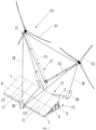
- FIGS. 1 to 5 show a floating wind turbine 100 according to an embodiment of the present disclosure, including a wind deflector 1, a floating board 2, an angle adjustment mechanism 21, a floating foundation 22 and a tower 23.
- the floating foundation 22 is provided with a mounting position 24, the tower 23 is mounted at the mounting position 24 and the tower 23 is provided with a wind rotor 18.
- the floating board 2 is substantially horizontally mounted to the floating foundation 22, the wind deflector 1 is hinged to the floating board 2, and an opening between the wind deflector 1 and the floating board 2 faces the tower 23.
- the angle adjustment mechanism 21 is operably connected to the wind deflector 1 to adjust an angle between the wind deflector 1 and the floating board 2.
- the wind deflector 1, the floating board 2, and the angle adjustment mechanism 21 cooperatively constitute a wind guiding structure.
- the wind guiding structure may also include other components or adopt other structures.
- the above-mentioned wind guiding structure can guide and disturb the wind within a certain height range on a sea surface, so that more wind flow blows into a swept area of the wind rotor 18, thereby improving a wind energy capture efficiency, and increasing a generated electrical energy.
- the wind deflector 1 and the floating board 2 may also be supported by a fixed bracket, so that the angle of the wind deflector 1 relative to the floating board 2 is a constant value.
- the tower 23 may be an airfoil tower.
- the airfoil tower includes a support arm 16 and two airfoil arms 15 located at an upper end of the support arm 16, more specifically, the two airfoil arms 15 are a first airfoil arm 151 and a second airfoil arm 152.
- a lower end of the support arm 16 is mounted at the mounting position 24.
- the wind rotor 18 may include a first wind rotor 181 provided on the first airfoil arm 151 and a second wind rotor 182 provided on the second airfoil arm 152. It should be understood that the first wind rotor 181 and the second wind rotor 182 can be driven by wind to rotate, so that wind energy can be converted into electrical energy.
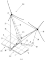
- the wind deflector 1 may include two or more sub-boards that are hinged to the floating board 2, respectively.
- the angle adjustment mechanism 21 may include two or more sub-angle adjustment mechanisms, each sub-board is operably connected to the corresponding sub-angle adjustment mechanism.
- the wind deflector 1 may include a first sub-board 111 and a second sub-board 112 that are hinged to the floating board 2, respectively.
- the first sub-board 111 may correspond to the first wind rotor 181 to guide the wind to the first wind rotor 181.
- the second sub-board 112 may correspond to the second wind rotor 182 to guide wind force toward the second wind rotor 182.
- the angle adjustment mechanism 21 may include a first sub-angle adjustment mechanism 211 and a second sub-angle adjustment mechanism 212.
- the first sub-angle adjustment mechanism 211 is operably connected to the first sub-board 111 to adjust an angle between the first sub-board 111 and the floating board 2
- the second sub-angle adjustment mechanism 212 is operably connected to the second sub-board 112 to adjust an angle between the second sub-board 112 and the floating board 2.
- the angle adjustment mechanism 21 to include the first sub-angle adjustment mechanism 211 and the second sub-angle adjustment mechanism 212, swing angles of the first sub-board 111 and the second sub-board 112 can be adjusted independently.
- the wind turbine deviates from a wind direction, according to a direction deviating from the wind direction, by adjusting respective stretching/folding states of the first sub-board 111 and the second sub-board 112, an eccentric moment is generated to assist the wind turbine to rotate around an anchor point with a turret bearing at an end of the floating foundation 22 located in an upwind direction, so as to assist the yaw to wind.
- a small gap may be provided between the two wind deflectors, when the swing angle of the first sub-board 111 or the second sub-board 112 is adjusted independently, the first sub-board 111 and the second sub-board 112 will not affect each other.
- the floating foundation 22 may include a first floating arm 221, a second floating arm 222, and a third floating arm 223 that are connected in a Y shape.
- a length of the first floating arm 221 may be greater than that of the second floating arm 222 and the third floating arm 223.
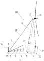
- the mounting position 24 is provided at a joint between the first floating arm 221, the second floating arm 222, and the third floating arm 223, the tower 23 is preferably mounted at the mounting position 24 obliquely.
- the floating board 2 may be mounted to the first floating arm 221.
- the floating board 2 may be symmetrically arranged with respect to the first floating arm 221, so that the floating board 2 includes a first floating board area 201 located on one side of the first floating arm 221 and a second floating board area 202 located on the other side of a floating arm 221.
- the first sub-board 111 and the first floating board area 201 can be hinged through a first hinge shaft 231, the second sub-board 112 and the second floating board area 202 can be hinged through a second hinge shaft 232.
- the first hinge shaft 231 and the second hinge shaft 232 may be coaxially arranged.
- the floating wind turbine 100 may further include at least one first buoy 4, the at least one first buoy 4 is mounted, for example, below the floating board 2.
- the first buoy 4 may be symmetrically mounted to a lower surface of the floating board 2 along the first floating arm 221. The first buoy 4 cooperates with the floating board 2 to improve a floating performance of the overall wind guiding structure.
- the angle between the wind deflector 1 (for example, each sub-board of the wind deflector 1) and the floating board 2 is in a range from 10° to 50°.
- the swing angle of the wind deflector 1 can be adjusted by the angle adjustment mechanism 21, the swing range of the wind deflector 1 can be adjusted to be 10° to 50°.
- the wind deflector 1 (each sub-board of the wind deflector 1) may include a plurality of flat boards 9 or curved boards arranged uniformly and coplanarly.
- the wind deflector 1 can be made in pieces, each sub-board can be spliced by a plurality of small boards on a frame structure as needed.
- a material of a board surface of each small board can be made of steel plate or glass steel plate or other metal or non-metallic material, which can meet environmental conditions and strength requirements.
- a shape of the board surface can be made into a straight line or a curved shape to enhance the wind guiding effect. The specific shape of the curved board surface is determined according to the design requirements.
- both the first sub-board 111 and the second sub-board 112 may be flat boards or curved boards.
- the floating board 2 may include a plurality of the flat boards 9 arranged uniformly.
- the floating board 2 floats on the sea surface and is configured to support a weight of the wind deflector 1 and a support frame.
- the floating board 2 can be a closed flat board surrounded by a plurality of the flat boards 9, or can be a flat board with holes configured to locate the first buoy 4.
- the first buoy 4 cooperates with the floating board 2, which can improve the floating performance of the wind deflector 1 and prolong a service life of the wind deflector 1.
- the angle adjustment mechanism 21 can be mounted between the floating board 2 and the wind deflector 1.
- the angle adjustment mechanism 21 includes a hydraulic cylinder 5, a base 6, a connecting block 7, and a support rod 8 (including a first support rod 81 and a second support rod 82).
- the base 6 is mounted to the hinge shaft between each sub-board (the first sub-board 111 and the second sub-board 112) of the wind deflector 1 and the floating board 2.
- the hydraulic cylinder 5 is mounted to the base 6.
- a telescopic rod 25 of the hydraulic cylinder 5 faces the tower 23.
- the connecting block 7 is mounted to the telescopic rod 25 of the hydraulic cylinder 5. Both ends of the first support rod 81 are hinged to the connecting block 7 and the floating board 2, respectively, and both ends of the second support rod 82 are hinged with connecting block 7 and wind deflector 1, respectively.
- a plurality of hydraulic cylinders 5, the connecting blocks 7, the first support rods 81, and the second support rods 82 may be provided.
- the plurality of hydraulic cylinders 5 are connected in sequence, the connecting block 7 is fixed to the telescopic rod 25 of each hydraulic cylinder 5.
- Each of the connecting blocks 7 is connected to the floating board 2 and the wind deflector 1 through the corresponding first support rod 81 and second support rod 82.
- the telescopic movement of the hydraulic cylinder 5 enables the first support rod 81 and the second support rod 82 to rotate around a hinge point at an end thereof, so that the first support rod 81 and the second support rod 82 are stretched or folded, thus the angle between the sub-board (the first sub-board 111 or the second sub-board 112) corresponding to the angle adjustment mechanism 21 and the floating board 2 is changed.
- the angle adjustment mechanism 21 is provided between the first sub-board 111 and the floating board 2 and between the second sub-board 112 and the floating board 2, (for example, the angle adjustment mechanism 21 corresponding to the first sub-board 111 is referred to as a first sub-angle adjustment mechanism 211, and the angle adjustment mechanism 21 corresponding to the second sub-board 112 is referred to as a second sub-angle adjustment mechanism 212), so that the swing angles of the first sub-board 111 or the second sub-board 111 can be adjusted independently.
- the angle of the wind deflector 1 can be adjusted by hydraulic drive.
- a wind speed is too large, by reducing an opening angle of the wind deflector 1, a wind blocking area is reduced, thereby reducing the wind load on the wind deflector 1.
- a design difficulty of a support structure of the wind deflector 1 and a foundation mooring system of the wind turbine is significantly reduced, and the structural safety is ensured.
- the first sub-board 111 or the second sub-board 112 can be retracted independently, so that wind resistances of the first sub-board 111 and the second sub-board 112 are different, thereby the eccentric moment is generated to assist the yaw of the floating wind turbine 100 to face the wind, improve the accuracy of facing to the wind, and thereby increase the power generation.
- a hydraulic power unit may be provided inside the second buoy 20 of the floating foundation 22 and connected to the hydraulic cylinder 5 through a pipeline.
- the floating wind turbine 100 may further include an engine room 17, the engine room 17 is mounted to an end of the tower 23 respectively.
- the wind rotor 18 is mounted to an end of the engine room 17 away from the wind deflector 1.
- a shape of the airfoil arm 15 is similar to a wing of an airplane, wind resistance can be reduced by this arrangement.
- the airfoil arm 15 may also have a predetermined cable connection point, the cable connection point and the floating foundation 22 are pre-tightenedly connected through a cable 19 to improve stability.
- both the floating foundation 22 and the tower 23 are Y-shaped, which reserves the mounting position for the wind guiding structure.
- the wind guiding structure is mounted on the floating wind turbine 100, when the lower wind blows through the wind deflector 1, the wind will flow obliquely upward under a guidance of the wind deflector 1 and accelerate to flow toward the swept area of the two wind rotors 18, so that an airflow velocity and density in the swept area of the two wind rotors 18 are increased, and the wind energy capture capability of the wind rotors 18 is greatly increased, thereby significantly improving the generated electrical energy of the wind turbine 100.
- the first floating arm 221 is located in the upwind direction
- the second floating arm 222 and the third floating arm 223 are located in a downwind direction.
- An inclined direction of the support arm 16 may be a direction away from the first floating arm 221.
- the support arms 15, 16, the engine room 17 and the wind rotor 18 are moved to the inclined direction as a whole.
- a thrust generated by the wind acting on the wind rotor 18 and the support arm 16 increases relative to a distance from the anchor point at the end of the floating foundation, thereby increasing the yaw restoring moment generated by the wind thrust, which is conducive to the realization of passive yaw to wind.
- the floating wind turbine 100 may also include the cables 19 and a plurality of second buoys 20.
- Each cable 19 may be a steel strand.
- the second buoys 20 can be respectively mounted on the other ends of the three floating arms 3 (the first floating arm 221, the second floating arm 222, and the third floating arm 223), each of the second buoys 20 can be connected to the corresponding engine room 17 through the cable 19.
- the two obliquely arranged airfoil arms 15 can ensure stability though the stay cables 29.
- an inside of the floating arm 3 may have a cavity. Water can be injected into the cavity to increase a buoyancy of the floating foundation 22.
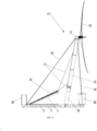
- This embodiment is a modification of the above-mentioned first embodiment. Compared with the above-mentioned first embodiment, this embodiment mainly has the following differences. If there is no conflict, other features of this embodiment can be substantially the same as those of first embodiment.
- the angle adjustment mechanism 21 can be mounted between the tower 23 and the wind deflector 1.
- the angle adjustment mechanism 21 includes a frame 10, a steel cable 11, and a hoist (not shown).
- the frame 10 is mounted to both sides of the wind deflector 1, a first side of the frame 10 is hinged to the floating board 2, and a second side of the frame 10 opposite to the first side has a steel cable connection point 13.
- the tower 23 is provided with a steel cable through hole 14 corresponding to the steel cable connection point 13, the hoist is mounted in the tower 23, one end of the steel cable 11 is fixed to the steel cable connection point 13, the other end of the steel cable 11 extends though the steel cable through hole 14 and is connected to the hoist.
- each sub-board (the first sub-board 111 and the second sub-board 112) of the wind deflector 1 can be made of canvas material to form a panel board.
- the panel board made of canvas is fixed to the frame 10 of each sub-board.
- the frames 10 on both sides of each sub-board of the wind deflector 1 can be made of steel, one end of each frame 10 can be hinged to the floating board 2, and the other end of each frame 10 can be connected to the steel cable 11.
- the panel board made of canvas is fixed to the frame 10, and forms a curved surface as a wind guiding surface under an action of wind load.
- each sub-board of the wind deflector 1 is not limited to be composed of canvas and the frame 10.
- sub-boards composed of canvas and frame 10 can be used in the fixed wind deflector.
- the sub-board composed of canvas and the frame 10 can also be used in the above-mentioned first embodiment.
- the swing angle of each sub-board of the wind deflector 1 is adjusted by driving the hoisting steel cable, so that elements such as the hydraulic cylinder 5 and the support rod 8 in the above-mentioned first embodiment can be omitted.
- two groups of steel cables 11 are used to pull each sub-board obliquely, and each group of steel cables 11 is driven by the hoist, so as to adjust the swing angle of each sub-board of the wind deflector 1.
- the frames 10 can be mounted on the left and right sides of each sub-board of the wind deflector 1, respectively.
- the steel cable connection points 13 are respectively provided on each frame 10, a plurality of the steel cable through hole 14 are provided on the airfoil arm 15.
- a hoisting mechanism (not shown) is mounted in the airfoil arm 15.
- each steel cable 11 is connected to the frames 10 on both sides of each sub-board of the wind deflector 1, and the other end of each steel cable 11 reaches corresponding position of the tower 23 of the wind turbine 100 in a vertical plane parallel to the wind direction, and enters the inside of the tower 23 along the corresponding steel cable though hole 14 of the airfoil arm 15 to be connected to the hoisting mechanism, thereby driving the steel cable 11 through the hoist.
Landscapes
- Engineering & Computer Science (AREA)
- Combustion & Propulsion (AREA)
- Mechanical Engineering (AREA)
- Chemical & Material Sciences (AREA)
- Sustainable Energy (AREA)
- Life Sciences & Earth Sciences (AREA)
- Sustainable Development (AREA)
- General Engineering & Computer Science (AREA)
- Fluid Mechanics (AREA)
- Physics & Mathematics (AREA)
- Ocean & Marine Engineering (AREA)
- Architecture (AREA)
- Civil Engineering (AREA)
- Structural Engineering (AREA)
- Wind Motors (AREA)
Applications Claiming Priority (2)
| Application Number | Priority Date | Filing Date | Title |
|---|---|---|---|
| CN202011079262.3A CN112065650B (zh) | 2020-10-10 | 2020-10-10 | 一种具有导风结构的漂浮式风力发电机组 |
| PCT/CN2021/096077 WO2022073349A1 (fr) | 2020-10-10 | 2021-05-26 | Unité de générateur éolien flottante |
Publications (2)
| Publication Number | Publication Date |
|---|---|
| EP4148268A1 true EP4148268A1 (fr) | 2023-03-15 |
| EP4148268A4 EP4148268A4 (fr) | 2024-06-26 |
Family
ID=73655833
Family Applications (1)
| Application Number | Title | Priority Date | Filing Date |
|---|---|---|---|
| EP21876872.9A Withdrawn EP4148268A4 (fr) | 2020-10-10 | 2021-05-26 | Unité de générateur éolien flottante |
Country Status (5)
| Country | Link |
|---|---|
| EP (1) | EP4148268A4 (fr) |
| JP (1) | JP2023533876A (fr) |
| KR (1) | KR102786139B1 (fr) |
| CN (1) | CN112065650B (fr) |
| WO (1) | WO2022073349A1 (fr) |
Families Citing this family (7)
| Publication number | Priority date | Publication date | Assignee | Title |
|---|---|---|---|---|
| CN112065650B (zh) * | 2020-10-10 | 2025-04-22 | 明阳智慧能源集团股份公司 | 一种具有导风结构的漂浮式风力发电机组 |
| CN113279901A (zh) * | 2021-07-01 | 2021-08-20 | 中国华能集团清洁能源技术研究院有限公司 | 一种机舱带有辅助支撑结构的双风轮风电机组 |
| CN114892838A (zh) * | 2022-06-02 | 2022-08-12 | 山西四建集团有限公司 | 一种超高层建筑砌砖的降风力装置 |
| CN115201509B (zh) * | 2022-07-13 | 2025-07-04 | 江苏科技大学 | 一种具有自动转向功能的风速测试装置 |
| CN115788800B (zh) * | 2022-12-30 | 2025-11-21 | 国家电投集团灵丘东方新能源发电有限公司 | 一种风力发电机组的导流装置及其控制方法 |
| CN118224046B (zh) * | 2024-03-13 | 2024-12-06 | 三峡大学 | 一种环境自适应漂浮式风电机组及其运行控制方法 |
| CN120798650B (zh) * | 2025-08-28 | 2026-04-24 | 山东银丰能源科技有限公司 | 一种水平翼角度可调整的水平翼风力发电机 |
Family Cites Families (16)
| Publication number | Priority date | Publication date | Assignee | Title |
|---|---|---|---|---|
| DK177081B1 (da) * | 2005-12-16 | 2011-06-20 | Lm Glasfiber As | Vindenergianlæg med strømningsflader |
| KR100948788B1 (ko) * | 2007-10-24 | 2010-03-24 | 삼성중공업 주식회사 | 부유식 멀티 풍력터빈 |
| TW201100637A (en) * | 2009-05-19 | 2011-01-01 | fu-zhang Liao | Wind-powered solar energy electricity generation mechanism |
| KR101291356B1 (ko) * | 2011-06-08 | 2013-07-30 | 삼성중공업 주식회사 | 풍력발전기용 기류 상승장치 |
| NO2776494T3 (fr) * | 2014-07-01 | 2018-09-29 | ||
| KR101636199B1 (ko) * | 2015-03-19 | 2016-07-05 | 유용선 | 풍력 및 태양광을 이용한 복합에너지 발전장치 |
| JP2019060237A (ja) * | 2015-12-25 | 2019-04-18 | 株式会社日立製作所 | 風車システムまたはウィンドファーム |
| DE102016110290B4 (de) * | 2016-06-03 | 2021-11-25 | Aerodyn Consulting Singapore Pte Ltd | Schwimmende Windenergieanlage mit einer Mehrzahl von Energiewandlungseinheiten |
| EP3701142B1 (fr) * | 2017-10-25 | 2022-12-07 | Winnowave SL | Système de guidage de vent pour éolienne |
| CN107813707B (zh) * | 2017-10-26 | 2019-08-02 | 宋志全 | 一种电动车能量收集转换装置 |
| CN109838351B (zh) * | 2017-11-24 | 2020-09-11 | 黄灿光 | 多风力发电机浮式自动对风水上风力发电设备 |
| US10465657B2 (en) * | 2017-12-07 | 2019-11-05 | Makani Technologies Llc | Methods and systems for controlling motion of floating ground station |
| CN108252866A (zh) * | 2018-03-06 | 2018-07-06 | 大连理工大学 | 一种基于浮式风机和潮流能装置的深海能源集成系统 |
| CN111089029B (zh) * | 2018-10-24 | 2021-05-04 | 北京金风科创风电设备有限公司 | 风力发电机组的导流装置及其控制方法、风力发电机组 |
| CN212838171U (zh) * | 2020-10-10 | 2021-03-30 | 明阳智慧能源集团股份公司 | 一种具有导风结构的漂浮式风力发电机组 |
| CN112065650B (zh) * | 2020-10-10 | 2025-04-22 | 明阳智慧能源集团股份公司 | 一种具有导风结构的漂浮式风力发电机组 |
-
2020
- 2020-10-10 CN CN202011079262.3A patent/CN112065650B/zh active Active
-
2021
- 2021-05-26 EP EP21876872.9A patent/EP4148268A4/fr not_active Withdrawn
- 2021-05-26 JP JP2023523319A patent/JP2023533876A/ja active Pending
- 2021-05-26 KR KR1020227042629A patent/KR102786139B1/ko active Active
- 2021-05-26 WO PCT/CN2021/096077 patent/WO2022073349A1/fr not_active Ceased
Also Published As
| Publication number | Publication date |
|---|---|
| JP2023533876A (ja) | 2023-08-04 |
| KR20230003259A (ko) | 2023-01-05 |
| CN112065650A (zh) | 2020-12-11 |
| EP4148268A4 (fr) | 2024-06-26 |
| CN112065650B (zh) | 2025-04-22 |
| WO2022073349A1 (fr) | 2022-04-14 |
| KR102786139B1 (ko) | 2025-03-24 |
Similar Documents
| Publication | Publication Date | Title |
|---|---|---|
| EP4148268A1 (fr) | Unité de générateur éolien flottante | |
| US6929450B2 (en) | Turbine apparatus and method | |
| CN115258071B (zh) | 一种导流式海上风力发电平台及海上风力发电系统 | |
| DK2895740T3 (en) | DRIED WINDING SYSTEM FOR WIND ENERGY USE | |
| DK181971B1 (en) | Floating vessel for energy harvesting | |
| CN116292124B (zh) | 一种风机、浮动平台和系泊系统一体化耦合的风电装备 | |
| US11384736B1 (en) | Floating offshore wind turbine system, apparatus and method | |
| CN117536792A (zh) | 海上漂浮式风机基础及海上风力发电机 | |
| WO2024012210A1 (fr) | Éolienne à axe vertical à rotors multiples pourvue d'un cadre de support rotatif | |
| EP4248082B1 (fr) | Appareil de production d'énergie | |
| CN212838171U (zh) | 一种具有导风结构的漂浮式风力发电机组 | |
| WO2011122895A2 (fr) | Appareil de génération d'énergie utilisant un fluide | |
| US20240026862A1 (en) | System for Offshore Power Generation | |
| CN211038938U (zh) | 一种塔扇风力发电机组 | |
| WO2021157498A1 (fr) | Équipement d'éolienne et pale d'éolienne | |
| CN119844288B (zh) | 具有双向自动伸缩圆柱涡流发生器的大型垂直轴风力机 | |
| KR102817240B1 (ko) | 수직형 대용량 풍력발전기 | |
| CN111997841A (zh) | 一种漂浮式风机发电机组 | |
| CN116792261B (zh) | 一种漂浮式风电平台姿态调控系统 | |
| FI130041B (en) | Method and apparatus for a Darrieus wind turbine comprising adjustable geometry | |
| US20240141866A1 (en) | Cross-flow wind turbine with twin blades and inclined rotation axes | |
| CN120246180A (zh) | 一种主动偏航的单点系泊漂浮式风机平台 | |
| JP2017072056A (ja) | ヨット型風力発電装置 |
Legal Events
| Date | Code | Title | Description |
|---|---|---|---|
| STAA | Information on the status of an ep patent application or granted ep patent |
Free format text: STATUS: THE INTERNATIONAL PUBLICATION HAS BEEN MADE |
|
| PUAI | Public reference made under article 153(3) epc to a published international application that has entered the european phase |
Free format text: ORIGINAL CODE: 0009012 |
|
| STAA | Information on the status of an ep patent application or granted ep patent |
Free format text: STATUS: REQUEST FOR EXAMINATION WAS MADE |
|
| 17P | Request for examination filed |
Effective date: 20221206 |
|
| AK | Designated contracting states |
Kind code of ref document: A1 Designated state(s): AL AT BE BG CH CY CZ DE DK EE ES FI FR GB GR HR HU IE IS IT LI LT LU LV MC MK MT NL NO PL PT RO RS SE SI SK SM TR |
|
| DAV | Request for validation of the european patent (deleted) | ||
| DAX | Request for extension of the european patent (deleted) | ||
| A4 | Supplementary search report drawn up and despatched |
Effective date: 20240524 |
|
| RIC1 | Information provided on ipc code assigned before grant |
Ipc: B63B 1/32 20060101ALI20240517BHEP Ipc: B63B 35/44 20060101ALI20240517BHEP Ipc: F03D 13/25 20160101ALI20240517BHEP Ipc: F03D 7/04 20060101ALI20240517BHEP Ipc: F03D 1/04 20060101AFI20240517BHEP |
|
| STAA | Information on the status of an ep patent application or granted ep patent |
Free format text: STATUS: THE APPLICATION IS DEEMED TO BE WITHDRAWN |
|
| 18D | Application deemed to be withdrawn |
Effective date: 20241212 |