EP4148405B1 - Système et procédé d'étalonnage de capteur - Google Patents
Système et procédé d'étalonnage de capteur Download PDFInfo
- Publication number
- EP4148405B1 EP4148405B1 EP21195483.9A EP21195483A EP4148405B1 EP 4148405 B1 EP4148405 B1 EP 4148405B1 EP 21195483 A EP21195483 A EP 21195483A EP 4148405 B1 EP4148405 B1 EP 4148405B1
- Authority
- EP
- European Patent Office
- Prior art keywords
- thermos
- elongate
- cavity
- fluid
- fluid directing
- Prior art date
- Legal status (The legal status is an assumption and is not a legal conclusion. Google has not performed a legal analysis and makes no representation as to the accuracy of the status listed.)
- Active
Links
Images




Classifications
-
- G—PHYSICS
- G01—MEASURING; TESTING
- G01K—MEASURING TEMPERATURE; MEASURING QUANTITY OF HEAT; THERMALLY-SENSITIVE ELEMENTS NOT OTHERWISE PROVIDED FOR
- G01K15/00—Testing or calibrating of thermometers
- G01K15/002—Calibrated temperature sources, temperature standards therefor
-
- G—PHYSICS
- G01—MEASURING; TESTING
- G01K—MEASURING TEMPERATURE; MEASURING QUANTITY OF HEAT; THERMALLY-SENSITIVE ELEMENTS NOT OTHERWISE PROVIDED FOR
- G01K19/00—Testing or calibrating calorimeters
-
- G—PHYSICS
- G01—MEASURING; TESTING
- G01K—MEASURING TEMPERATURE; MEASURING QUANTITY OF HEAT; THERMALLY-SENSITIVE ELEMENTS NOT OTHERWISE PROVIDED FOR
- G01K7/00—Measuring temperature based on the use of electric or magnetic elements directly sensitive to heat ; Power supply therefor, e.g. using thermoelectric elements
- G01K7/02—Measuring temperature based on the use of electric or magnetic elements directly sensitive to heat ; Power supply therefor, e.g. using thermoelectric elements using thermoelectric elements, e.g. thermocouples
-
- G—PHYSICS
- G01—MEASURING; TESTING
- G01K—MEASURING TEMPERATURE; MEASURING QUANTITY OF HEAT; THERMALLY-SENSITIVE ELEMENTS NOT OTHERWISE PROVIDED FOR
- G01K7/00—Measuring temperature based on the use of electric or magnetic elements directly sensitive to heat ; Power supply therefor, e.g. using thermoelectric elements
- G01K7/16—Measuring temperature based on the use of electric or magnetic elements directly sensitive to heat ; Power supply therefor, e.g. using thermoelectric elements using resistive elements
- G01K7/22—Measuring temperature based on the use of electric or magnetic elements directly sensitive to heat ; Power supply therefor, e.g. using thermoelectric elements using resistive elements the element being a non-linear resistance, e.g. thermistor
Definitions
- the invention relates to a system and method for calibrating a temperature sensor according to claims 1 and 18, respectively.
- Temperature sensors find used in many applications of use and in some of applications of use, such as food production, production of chemicals, drugs and medicaments or other production, a correct determination of a temperature may be of vital importance which determination requires a calibration of a given sensor to e.g. learn to which extend the sensor provides a correct read-out. Further, a sensor may drift over time, whereby a calibration of the sensor e.g. during manufacturing may only be valid for a shorter or longer period of time such that a recalibration of the sensor may be needed at some points in time.
- Calibration may in some instances be carried out by controlling the temperature of a fluid surrounding the temperature sensor and use a reference temperature sensor defined to provide correct read-outs placed in the fluid.
- temperature sensors are designed to fit into a production facility whereby the actual sensing element may be encapsulated into a structure used to fit the production facility and at the same time place the sensing element in a desired measuring position.
- a complex heat transfer occurs between the fluid surrounding the temperature sensor and the actual sensing element, which complex heat transfer typically involves one or more timescales at which transfer occurs.
- a calibration carried out at a single temperature may not be sufficient as e.g. a deviation between read-out the sensor and the correct temperature may depend on the actual temperature level at which the calibration is carried out.
- an improved system and method for calibrating a temperature sensor would be advantageous, and in particular a more efficient and/or reliable system and method for calibrating a temperature sensor would be advantageous.
- CN 209 979 097 U discloses a temperature calibration bath comprising a stirrer and a heater on one side of the tank, and a partition wall separating this side from the temperature sensor to be calibrated.
- the wall has ducts such that due to enforced circulation of the calibration liquid temperature gradients are decreased.
- the controller may further be configured to obtain measurements from the reference thermos element and thermos element and provide a calibration for the thermos element on the basis of said measurements.
- the system may further comprising a stirrer to promote a flow of fluid going upward in the outer flow passage and downward in the inner flow passage or vice versa, said stirrer preferably comprising a magnetic stirrer or a stirrer arranged on a shaft rotated by an electrical motor.
- the temperature sensor may comprise at a position distal to the first end of the elongate element a socket from which the elongate element extend, and wherein said socket may has a thickness and a diameter or equivalent diameter being larger than a diameter or equivalent diameter of the elongate element.
- the elongate fluid directing element may comprising
- the lower end of the elongate fluid directing element may be bevelled.
- the elongate fluid directing element may comprise at its upper end a supporting flange extending horizontally beyond a cross section of the open end of the cavity so that the temperature sensor may be supported at the open end of the cavity.
- the system may comprise a basin arranged at the open end of the cavity, said basin may comprising an bottom with an through going opening so that the basin may be in fluid communication with the cavity and an wall protruding upwardly from the bottom and may have an internal diameter or equivalent diameter being larger than the internal diameter or equivalent diameter of the open end of the cavity.
- the elongate fluid directing element has a wall thickness of larger than 2.0 mm, such as larger than 3.0 mm, preferably larger than 5.0 mm and smaller than 12.0 mm such as smaller than 10.0 mm and preferably a wall thickness of 9.00 mm.
- the elongate fluid directing element may have a height being less than a height of the tubular wall.
- the elongate fluid directing element is made, such as made solely from aluminium, copper, brass or stainless steel.
- the fluid directing element may comprise a number vertically extending panels, arranged on a perimeter of e.g. a circle with a space in between each panels.
- the electrical thermos element may comprise a thermistor such as a negative temperature coefficient resistor or a positive temperature coefficient resistor.
- the electrical thermos element may comprise a thermocouple.
- the reference thermos element may be arranged within the cavity at a position having substantially the same temperature as the thermos element, such as at the same horizontal level at which the thermos element may be arranged.
- the elongate element, the elongate fluid directing element and the tubular wall may be co-axially arranged.
- the energy source comprises one or more electrical heating elements, such as ohmic heating element(s), Peltier element(s), a Stirling cooler or combinations thereof.
- electrical heating elements such as ohmic heating element(s), Peltier element(s), a Stirling cooler or combinations thereof.
- the invention further relates to a method being adapted to enable a calibration of a temperature sensor, said method may be utilizing the system, and may comprise:
- the calibration may comprise determining a correction for the temperatures sensor, wherein the correction may be an arithmetic correction or a database storing deviations as a function of measured temperatures.
- a surface facing the inner surface of receptacle is referred to as an outer surface unless otherwise presented.
- Elongate is preferably used to reference an element having a longitudinal extension being larger than a transverse extension of the element.
- the invention relates to a system 1 for calibrating a temperature sensor 2.
- the temperature sensor 2 is typically of a type which is to be used in production facility or other facility where the temperature of medium, which may be liquid or gaseous, is to be monitored.
- the temperature sensor 2 does therefore not as such forms an integral part of the system as the temperature sensor 2 may be arranged in the system for calibration and after calibration be placed in the facility where the temperature is to be monitored. Thus, in use, the system has received the temperature sensor 2.
- the temperature sensor 2 has as shown in the figures an elongate element 3 having at a first end 4 a thermos element 5.
- the thermos element 5 may be an electrical thermos element but it may also be a mechanical thermos element 5.
- the thermos element 5 provides a read-out representing the temperature as sensed by the temperature sensor 2.
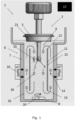
- the system 1 comprising a receptacle 6 which inter alia receives the elongate element 3 of the temperature sensor 2.
- the receptacle 6 has a tubular wall 7, such as a cylindrical wall, closed at a lower end by a bottom 8 thereby defining an open-ended cavity 9.
- This cavity 9 is configured to hold a liquid by being impermeable to the fluid to be added to the receptacle 6 in the calibration procedure. It is also configured to receive at least a part of said elongate element 3 at least to an extent so that the first end 4 with the thermos element 5 is contained within cavity 9. Thereby, when a fluid is provided in the receptacle 6, the thermos element 5 is submerged in the fluid.
- the temperature of the fluid contained in the receptacle 6 is to be controlled, e.g. heated or cooled to one or more temperatures.
- a controllable energy source 10 is applied and the energy source 10 is configured to add to or remove heat from the cavity 9.
- a predefined temperature is often used during calibration, and firstly the fluid contained in the receptacle 6 is heated or cooled by the controllable energy source 10 to the predefined temperature.
- the reference thermos element 19 provides a stable temperature, being a temperature within a predefined range, then secondly the temperature sensor 2 measures and provides a temperature. This calibration process is preferably carried out multiple times, using different predefined temperatures, in order to calibrate the temperature sensor 2.
- the energy source 10 is arranged on an outer surface of the tubular wall 7.
- the energy source 10 may be arranged differently, such as embedded in the tubular wall 7, on the inner surface of the tubular wall 7, arranged in the cavity 9 so as to be in direct contact with the fluid or even combinations thereof.
- a predefined temperature is used and after a predefined amount
- the receptacle has a longitudinal extension in vertical direction which may give rise to a vertical and/or horizontal temperature gradient in the fluid contained in the receptacle 6.
- the temperature gradient may also be provided by the upper end of the temperature sensor 2 having a relatively high mass which may not have the same temperature as the fluid whereby a conduction of heat may be provided between the elongate element 3 and the upper end of the temperature sensor 2.
- the system 1 has an elongate fluid directing element 11 typically configured to assist in creating a circulating motion of the fluid.
- the elongate fluid directing element 11 has an upper end 12 and a lower end 13 and is arranged within the cavity 9 and is dimensioned to provide an outer flow passage 14 between an outer surface 15 of the fluid directing element 11 and an inner surface 16 of tubular wall 7, and an inner flow passage 18 inside and inner side the elongate fluid directing element 11.
- the outer flow passage 15 and the inner flow passage 18 are in fluid communication at the upper end 12 and at the lower end 13.
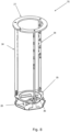
- the fluid directing element 11 may in preferred embodiments be a tubular or cylindrical element comprised by a solid wall, including in some embodiments through going openings.
- a fluid directing element is illustrated in fig. 9 .
- the system also comprises a reference thermos element 19 arranged within the cavity 9.
- This reference thermos element 19 is the element assigned to provide reference temperature measurements, that is the calibration of the temperature sensor 2 is made up against the measurements provided by the thermos element 19.
- a secondary or alternative reference temperature measurement may be carried out at a reference thermos element void 37 at another position different from reference thermos element 19.
- the reference thermos element void 37 is preferably arranged in the receptacle 6 close to the energy sources 10.
- a controller 17 is provided and the controller is configured to control the amount of heat added to or removed from the cavity 9 by controlling the energy source 10, obtain measurements from the reference thermos element 19 and thermos element 5 and, preferably, provide a calibration for the thermos element 5 on the basis of said measurements.
- thermos element is embedded in the tubular wall 7, and such a thermos element may be used to assisting in controlling the temperature in the receptacle 6.
- the system may comprising a stirrer 20 to promote a flow of fluid going upward in the outer flow passage 14 and downward in the inner flow passage 19 or vice versa.
- the stirrer 20 is a magnetic stirrer but other types of stirrers such stirrer arranged on a shaft rotated by an electrical motor may be used.
- the elongate fluid directing element 11 is in the embodiments shown as a cylindrical element, but it may be a tubular element having outer diameter or equivalent diameter (for a tubular element) being less than an inner diameter or equivalent inner diameter of the tubular wall 7.
- the elongate fluid directing element 11 is typically a straight element and the elongate fluid directing element 11 is typically defined by a tubular wall having thickness.
- the temperature sensor 2 may have at a position distal to the first end 4 of the elongate element 3 a socket 21, sometimes also referred to as a "process connector", from which the elongate element 3 extend.
- a socket may come in a variety of shapes, but for the purpose of disclosing the present invention, the socket 21 is in some embodiments defined to have a thickness and a diameter or equivalent diameter.
- the diameter or equivalent diameter of the socket 21 may be larger than a diameter or equivalent diameter of the elongate element 3, and the thickness of the socket 21 may be smaller, equal to or larger than diameter or equivalent diameter of the elongate element 3.
- the thickness is typically measured transversely to the diameter, and with reference to figs. 1 and 2 the thickness is measured in vertical direction whereas diameter is measured in horizontal direction.
- the fluid directing element 11 is a cylindrical element with no through going openings provided in the wall.
- the fluid directing element 11 has a shorter longitudinal extension than the depth of the receptacle 6 and is arranged within the receptacle 6 in a position providing an overflow passage at the upper end 12 and an underflow passage at the lower end 13.
- the fluid directing element 11 is typically suspended in position by not illustrated suspension element, such as spacers or fixation elements.
- the temperature sensor 2 in the embodiment shown in fig. 1 is typically suspended in the show position by suspension elements not illustrated.
- the elongate fluid directing element 11 has an outer diameter or equivalent outer diameter and a wall thickness providing an abutment surface 23 at the upper end 12.
- This abutment surface 23 is provided to abut with an underside of the temperature sensor 2.
- the temperature sensor 2 is accordingly arranged with at least a part of a lower surface 24 of the socket 21 abutting the abutment surface 23.
- a thermal contact between the fluid directing element and the socket 21 is provided so that heat may be conducted (as illustrated by the arrows in fig. 2 ) from the elongate fluid directing element 11 and to the socket 21 (or vice versa depending on the sign of temperature gradient).
- the abutment surface may also serves as a supporting element for the temperature sensor 2.
- the abutment surface 23 forms a closed area, whereby flow of fluid is substantially prevented or limited in between the abutment surface 23 and the lower surface 24 of the socket.
- the abutment may be provided so that the fluid may sieve out of the receptacle 6 in between the abutment surface 23 and the lower surface 24.
- Such a sieving possibility may be provided by the weight of the temperature sensor 2 is suitable low so that the weight do not provide a hermetic fluidic seal but allow for fluid to pass between the abutment surface 23 and the lower surface 24.
- a small opening 30 may be provided to allow fluid exchange as detailed below.
- two through going openings 25 are provided at the upper end of the elongate fluid directing element 11 to provide the fluid communication at the upper end 12. These through going openings are perhaps most clearly visible in fig. 3 . It is to be noted that the number of through going openings is not limited to two, as a single or a plurality of through going openings 25 may be provided. When more than one through going opening are provided they are typically evenly distributed, preferably along a perimeter of the fluid directing element at the upper end (12) thereof, to allow for a degree of symmetry in the fluid motion.
- an opening 26 is provided between said lower end 13 and the bottom 8. This opening 26 is in the illustrated embodiment provided by the lower end of the elongate fluid directing element 11 being positioned in distance from the bottom 8.
- the lower end 13 of the elongate fluid directing element is bevelled, although this is not essential for the operation of the invention.
- the orientation of the bevel may be provided depending on the orientation of the circulation.
- the elongate fluid directing element 11 shown in fig. 2 has at its upper end 12 a supporting flange 27 extending horizontally beyond a cross section of the open end of the cavity 9. This supporting flange rest on an upwardly facing surface of the open ended cavity 9 whereby the temperature sensor is supported at the open end of the cavity 9.
- the supporting flange 27 is comprised in a suspension element 31 as illustrated in fig. 6 .
- the suspension element 31 comprises a suspension element bottom 36, whereon the stirrer 20 may be placed.
- the suspension element bottom 36 is connected to a supporting rim 35 through one or more extending member(s) 34.
- the suspension element 31 comprises three extending members 34, but in other embodiments, it may be relevant to a different construction, such as two extending members 34, such as four extending members 34.
- the supporting flange 27 as detailed above, is arranged in the opposite end of the suspension element bottom 36, and connected to the extending members 34. Both the supporting flange 27 and the supporting rim 35 are preferably ring-shaped.
- the suspension element 31 besides serving as a suspension element for the fluid directing element 11, may also be used to limit fluid circulations and turbulence in the bottom part of the receptacle 6 around the opening 26, the bottom 8 and the lower end 13, and ensure that fluid is circulated around through both the inner flow passage 18 and the outer flow passage 14.
- the system has a basin 28 arranged at the open end of the cavity 9.
- the basin 28 has a bottom with a through-going opening 29 so that the basin 28 is in fluid communication with the cavity 9.
- the basin 28 also has a wall protruding upwardly from the bottom and having an internal diameter or equivalent diameter being larger than the internal diameter or equivalent diameter of the open end of the cavity 9.
- the basin 28 is furthermore dimensioned so as to receive the socket 21, or at least a section thereof.
- thermos element 5 It is beneficial to have the same heat transfer to the socket at many such as essentially all temperatures, as heat transfer to the socket influences the temperature measurement by thermos element 5. In the embodiment shown in fig. 1 , this has to be accomplished by adjusting liquid level with change of temperature or by adjusting sensor 2 height and/or position.
- a small opening 30 is provided in the flange 27 to allow fluid to be exchanged between the receptacle 6 and the basin as temperature changes but without creating liquid flow in the basin and thereby minimizing heat transfer to other surfaces of the socket 21 than 24.
- the fluid directing element 11 besides serving as an element directing fluid motion, the element 11 may also serve the purpose of conducting heat in the longitudinal direction of the element 11 towards or away from the socket 21 or in general.
- the wall thickness can be chosen according to a particular preferred used, preferably also taking into consideration the heat capacity and the heat transfer coefficient of the elongate fluid directing element 11.
- dimensions of the wall thickness of the elongate fluid directing element 11 is a wall thickness of larger than 2.0 mm, such as larger than 3.0 mm, preferably larger than 5.0 mm and smaller than 12.0 mm such as smaller than 10.0 mm and preferably a wall thickness of 9.00.
- the elongate fluid directing element 11 has in preferred embodiments a height being less than a height of the tubular wall 7.
- the elongate fluid directing element 11 may be made, such as made solely from, aluminium, copper, brass, or stainless steel. In further embodiments, heat pipes may be embedded in the elongate fluid directing element 11 to improve heat transfer.
- the fluid directing element 11 may in other embodiments comprise a number vertically extending panels, arranged on a perimeter of e.g. a circle with a space in between each panels.
- the electrical thermos element 5 is or comprised by a thermistor such as a negative temperature coefficient resistor or a positive temperature coefficient resistor. In other embodiments, the electrical thermos element 5 is or comprised by a thermocouple.
- the reference thermos element 19 is, as illustrated in figs. 1 and 2 , arranged within the cavity 9 at a position having substantially the same temperature as the thermos element 5. This may as disclosed be at the same horizontal level at which the thermos element 5 is arranged, and inside the elongate fluid directing element 11. However, as the motion of the fluid may provide a thermal equilibrium, in the sense that different positions in the receptacle has substantially equal temperature, the reference thermos element 19 may be placed at other positions within the receptacle 6.
- the elongate element 3 the elongate fluid directing element 11 and the tubular wall 7 may be co-axially arranged.
- the energy source may be one or more electrical sources, such as ohmic heating element(s), Peltier element(s), a Stirling cooler or combinations hereof.
- Calibration of a temperature sensor by use of the embodiments may typically involve the following steps.
- the system is set-up which involves arranging the temperature sensor in the cavity 9 and adding a fluid, such as silicon oil, water, cooking oil or an oil approved for pharmaceutical use, into the cavity in an amount sufficient to submerge the elongate fluid directing element and the electrical thermos element an at least a section of the elongate element.
- a fluid such as silicon oil, water, cooking oil or an oil approved for pharmaceutical use
- fluid is preferably added so that at least a part of the socket 21 becomes submerged having the fluid in contact with 24.
- the fluid may be selected in accordance with the specific use of the temperature sensor, and the conditions under which the temperature sensor 2 is to operate in a facility may be reflected in the choice of fluid, e.g. selecting a fluid having similar or equal fluid and heating characteristics to the fluid of the facility.
- the controller begin to control the energy source 10 to heat or cool the fluid in the cavity 9 to one or more temperatures. These temperatures are typically preselected and preferably selected to cover a span of operation of the temperature sensor 2. It worth noting that the temperature may be determined either by the reference thermos element 19 or a thermos element in the tubular wall 7 as a calibration of the thermos element 5 is to be determined.
- the elongate fluid direction element 11 may comprise a thermos element cavity 33 as illustrated in fig. 3 and adapted to hold and/or fit the reference thermos element 19. The thermos element cavity 33 ensures that the thermos element 19 is kept in place during the temperature measurements.
- thermos element 19 and thermos element 5 When a thermal equilibrium is established in the fluid for the selected temperature, a deviation, if any, between the measurement made by the reference thermos element 19 and the thermos element 5 is determined and this deviation is used as a calibration for temperature sensor 2.
- a thermal equilibrium may be established based on that, the temperature of thermos element 19 and thermos element 5 have not changed more than a predefined value in a predefined time. For example 0.05°C in 10 minutes.
- the calibration comprising determining a correction for the temperatures sensor 2, wherein the correction is an arithmetic correction or a database storing deviations as a function of measured temperatures.
- FIG. 7 illustrating experimental results in terms of temperature deviations when using multiple embodiments of the invention.
- the embodiment of the invention as illustrated in fig. 2 is shown as solid columns.
- the pattern filled columns illustrates laboratory baths.
- the experiments were carried out as comparative experiments between laboratory baths, which is a test facility in which the temperature of a fluid is determinable and controllable to an extend where it is assigned to be a true temperature, and in embodiment of the invention as illustrated in fig. 2 .
- the temperature sensor 2 is submerged in the bath at a temperature of 160 degrees Celsius and the temperature of the temperature sensor (2) is measured for different liquid levels relative to the lower surface (24) of the temperature sensor (2).
- the temperature sensor (2) was placed on the supporting flange (27).
- the temperature sensor (2) was supported by other means. Results from the embodiment of the invention as illustrated in fig. 1 is similar to laboratory baths.
- the system 1 further comprises a container 32 arranged within the cavity 9 and configured to a hold liquid.
- the diameter or equivalent diameter of the container 32 is normally smaller than the inner diameter or equivalent diameter of the receptacle 6 so that the container 32 fits snugly within the receptacle with a clearance between the container and the receptacle.
- dimension of the clearance is such as 0.7 mm smaller than the inner diameter of the receptacle 6, such as 0.3mm smaller than the inner diameter of the receptacle 6, such as 0.1mm smaller than the inner diameter of the receptacle 6.
- the lower limit for the clearance is selected so as to allow removal of the container, typically by hand.
- the diameter or equivalent diameter of the container 32 is measured from one inner surface of the tubular wall 16 to the opposite inner surface of the tubular wall 16.
- the container 32 is preferably used when multiple mediums are used for calibration(s), such as wet-medium calibration and a dry calibration, where the wet-medium calibration can be carried out with container 32 arranged in the cavity 9 and once a dry calibration is to be carried, the system can easily be configured for that purpose by removing the container 32.
- fig. 5 illustrating experimental results in terms of temperature deviations when using multiple embodiments of the invention.
- the embodiment of the invention as illustrated in fig. 1 is shown as a dashed graph
- the second embodiment of the invention as illustrated in fig. 2 is shown as a solid line
- measurements in laboratory bath is shown as a dotted line.
- the experiments were carried out as comparative experiments between laboratory baths, which is a test facility in which the temperature of a fluid is determinable and controllable to an extend where it is assigned to be a true temperature, and in embodiments of the invention.
- the temperature sensor 2 is submerged in the bath and the temperature was increased from -10 degrees Celsius to 160 degrees Celsius for both the laboratory baths and the embodiment of the invention.
- the deviation from calibration of solely the thermos element 5 was calculated based on both laboratory bath measurements and measurements obtained by embodiments of the invention.
- an embodiment of an elongate fluid directing element is shown having similarities with the embodiment shown in fig. 3 .
- the through going openings 25 arranged in different positions relatively to the reference thermos element cavity 33 as can be realized by a comparison of the two figures in question.
- the interior contours of elongate fluid direction elements are illustrated by dotted lines, which inter alia reveals a through-going passage 38 axially aligned with the notch 39.
- wiring of the reference thermos element to be placed in the cavity 33 may be led through the through going passage, the through going opening 25 and through the notch 39 and out and away from the notch 39.
- the reference thermos element may be arranged in the cavity 33 by leading it through the notch 39 and the through going passage 38.
- the embodiment of fig. 3 may comprise a similar through going passage extending between the notch 39 and the through going opening 33.
- a system for calibrating a temperature sensor comprising a temperature sensor 2, an elongate fluid directing element 11, a suspension element and a receptacle 6 (not shown).
Landscapes
- Physics & Mathematics (AREA)
- General Physics & Mathematics (AREA)
- Nonlinear Science (AREA)
- Measuring Temperature Or Quantity Of Heat (AREA)
Claims (19)
- Système (1) d'étalonnage d'un capteur de température (2), ledit système comprenant• ledit capteur de température (2) comprenant un élément allongé (3) comportant à une première extrémité (4) un élément thermos (5), qui est de préférence un élément thermos électrique ;• un réceptacle (6) comprenant une paroi tubulaire (7), telle qu'une paroi cylindrique, fermé à une extrémité inférieure par un fond (8) définissant ainsi une cavité (9) à extrémité ouverte, configurée pour retenir un liquide et pour recevoir au moins une partie dudit élément allongé (3) de sorte que la première extrémité (4) comportant l'élément thermos (5) est contenue à l'intérieur de la cavité (9) ;• une source d'énergie réglable (10) configurée pour introduire ou extraire de la chaleur dans ou de la cavité (9) ;• un élément allongé directeur (11) de fluide, qui est un élément tubulaire, tel qu'un élément cylindrique, ayant un diamètre ou diamètre équivalent externe qui est inférieur à un diamètre interne ou diamètre interne équivalent de la paroi tubulaire (7) et présentant une extrémité supérieure (12) et une extrémité inférieure (13), ledit élément directeur (11) de fluide est disposé à l'intérieur de la cavité (9) et étant dimensionné pour procurer un passage d'écoulement externe (14) entre une surface externe (15) de l'élément directeur (11) de fluide et une surface interne (16) de paroi tubulaire (7) et un passage d'écoulement interne (18) à un côté interne de l'élément allongé directeur (11) de fluide, le passage d'écoulement externe (15) et le passage d'écoulement interne (18) étant en communication fluidique à l'extrémité supérieure (12) et à l'extrémité inférieure (13) ;• un élément thermos de référence (19) disposé pour capter la température à l'intérieur de la cavité (9) ;• un régulateur (17) configuré pour régler la quantité de chaleur introduite dans ou extraite de la cavité (9).
- Système selon la revendication 1, dans lequel le régulateur est en outre configuré pour obtenir des mesures depuis l'élément thermos de référence (19) et l'élément thermos (5) et fournir un étalonnage pour l'élément thermos (5) sur la base desdites mesures.
- Système selon la revendication 1 ou 2, comprenant en outre un agitateur (20) pour faciliter un écoulement de fluide circulant vers le haut dans le passage d'écoulement externe (14) et vers le bas dans le passage d'écoulement interne (18) ou vice versa, ledit agitateur (20) comprenant de préférence un agitateur magnétique ou un agitateur disposé sur un arbre entraîné en rotation par un moteur électrique.
- Système selon l'une quelconque des revendications précédentes, dans lequel ledit capteur de température (2) comprend à une position distale par rapport à la première extrémité (4) de l'élément allongé (3) une douille (21) à partir de laquelle s'étend l'élément allongé (3), et dans lequel ladite douille (21) a une épaisseur et un diamètre ou diamètre équivalent qui est plus grand qu'un diamètre ou diamètre équivalent de l'élément allongé (3).
- Système selon l'une quelconque des revendications précédentes, dans lequel l'élément allongé directeur (11) de fluide comprend• un diamètre externe ou diamètre externe équivalent et une épaisseur de paroi offrant une surface de butée (23) à l'extrémité supérieure (12) et dans lequel le capteur de température (2) est disposé avec au moins une partie d'une surface inférieure (24) de la douille (21) venant buter contre ladite surface de butée (23) pour procurer un contact thermique entre l'élément directeur de fluide et la douille (21),• au moins une ouverture traversante (25) ou au moins deux ouvertures traversantes réparties, de préférence le long d'un périmètre de l'élément directeur de fluide à l'extrémité supérieure (12) de ce dernier, ladite/lesdites ouverture(s) traversante(s) (25) procurant ladite communication fluidique à l'extrémité supérieure (12),et dans lequel une ouverture (26) est disposée entre ladite extrémité inférieure (13) et ledit fond (8).
- Système selon la revendication 5, dans lequel l'extrémité inférieure (13) de l'élément allongé directeur de fluide est biseautée.
- Système selon la revendication 5 or 6, dans lequel l'élément allongé directeur (11) de fluide comprend à son extrémité supérieure (12) une bride de soutien (27) s'étendant horizontalement au-delà d'une section transversale de l'extrémité ouverte de la cavité (9) de sorte que le capteur de température est soutenu à l'extrémité ouverte de la cavité (9).
- Système selon l'une quelconque des revendications précédentes, comprenant en outre une cuvette (28) disposée à l'extrémité ouverte de la cavité (9), ladite cuvette (28) comprenant un fond comportant une ouverture traversante (29) de sorte que la cuvette (28) est en communication fluidique avec la cavité (9) et une paroi faisant saillie vers le haut à partir du fond et ayant un diamètre ou diamètre équivalent interne qui est plus grand que le diamètre ou diamètre équivalent interne de l'extrémité ouverte de la cavité (9).
- Système selon l'une quelconque des revendications précédentes, dans lequel l'élément allongé directeur (11) de fluide a une épaisseur de paroi supérieure à 2,0 mm, telle que supérieure à 3,0 mm, de préférence supérieure à 5,0 mm et inférieure à 12,0 mm, telle qu'inférieure à 10,0 mm et de préférence une épaisseur de paroi de 9,00 mm.
- Système selon l'une quelconque des revendications précédentes, dans lequel l'élément allongé directeur (11) de fluide a une hauteur qui est inférieure à une hauteur de la paroi tubulaire (7).
- Système selon l'une quelconque des revendications précédentes, dans lequel l'élément allongé directeur (11) de fluide est constitué de métal, tel que constitué uniquement d'aluminium, de cuivre, de laiton ou d'acier inoxydable ou d'une association de ceux-ci.
- Système selon l'une quelconque des revendications précédentes, comprenant en outre un élément de suspension (31) disposé dans le réceptacle (6), pour suspendre l'élément allongé directeur (11) de fluide.
- Système selon l'une quelconque des revendications précédentes, dans lequel l'élément thermos électrique (5) comprend une thermistance telle qu'une résistance à coefficient de température négatif ou une résistance à coefficient de température positif.
- Système selon l'une quelconque des revendications précédentes, dans lequel l'élément thermos électrique (5) comprend un thermocouple.
- Système selon l'une quelconque des revendications précédentes, dans lequel l'élément thermos de référence (19) est disposé à l'intérieur de la cavité (9) à une position ayant sensiblement la même température que l'élément thermos (5), par exemple au même niveau horizontal que celui sur lequel est disposé l'élément thermos (5).
- Système selon l'une quelconque des revendications précédentes, dans lequel l'élément allongé (3), l'élément allongé directeur (11) de fluide et la paroi tubulaire (7) sont disposés coaxialement.
- Système selon l'une quelconque des revendications précédentes, dans lequel la source d'énergie comprend un ou plusieurs éléments chauffants électriques, tels qu'élément(s) chauffant(s) ohmique(s), élément(s) Peltier, un refroidisseur Stirling ou des associations de ceux-ci.
- Procédé d'étalonnage d'un capteur de température (2), ledit procédé utilisant un système selon l'une quelconque des revendications précédentes, et comprenant les étapes consistant à :• disposer le capteur de température (2) dans la cavité (9) ;• introduire dans la cavité (9) un fluide, tel que de l'huile de silicone, de l'eau, de l'huile de cuisson ou une huile approuvée pour usage pharmaceutique, en une quantité suffisante pour submerger l'élément allongé directeur (11) de fluide et l'élément thermos (5) et au moins un segment de l'élément allongé (3) ;• régler la source d'énergie (10) pour chauffer ou refroidir le fluide dans la cavité (9) jusqu'à une ou plusieurs températures, la/les température(s) étant déterminée(s) par l'élément thermos de référence (19) ou l'élément thermos (6) ;• lorsqu'un équilibre thermique est établi dans le fluide pour ladite/lesdites une ou plusieurs température(s) :o déterminer en utilisant l'élément thermos (5) et l'élément thermos de référence (19) un écart entre ces deux températures, s'il existe, et étalonner le capteur de température (2) sur la base dudit écart.
- Procédé selon la revendication 18, dans lequel l'étalonnage comprend déterminer une correction pour le capteur de température (2), la correction étant une correction arithmétique ou une base de données mémorisant des écarts en fonction de températures mesurées.
Priority Applications (5)
| Application Number | Priority Date | Filing Date | Title |
|---|---|---|---|
| DK21195483.9T DK4148405T3 (da) | 2021-09-08 | 2021-09-08 | System og fremgangsmåde til kalibrering af en sensor |
| EP21195483.9A EP4148405B1 (fr) | 2021-09-08 | 2021-09-08 | Système et procédé d'étalonnage de capteur |
| PCT/EP2022/074847 WO2023036816A1 (fr) | 2021-09-08 | 2022-09-07 | Système d'étalonnage de capteur |
| CN202211091921.4A CN115655519A (zh) | 2021-09-08 | 2022-09-07 | 一种用于校准温度传感器的系统和方法 |
| US18/689,615 US20240344905A1 (en) | 2021-09-08 | 2022-09-07 | System for calibrating a sensor |
Applications Claiming Priority (1)
| Application Number | Priority Date | Filing Date | Title |
|---|---|---|---|
| EP21195483.9A EP4148405B1 (fr) | 2021-09-08 | 2021-09-08 | Système et procédé d'étalonnage de capteur |
Publications (2)
| Publication Number | Publication Date |
|---|---|
| EP4148405A1 EP4148405A1 (fr) | 2023-03-15 |
| EP4148405B1 true EP4148405B1 (fr) | 2025-01-08 |
Family
ID=77666347
Family Applications (1)
| Application Number | Title | Priority Date | Filing Date |
|---|---|---|---|
| EP21195483.9A Active EP4148405B1 (fr) | 2021-09-08 | 2021-09-08 | Système et procédé d'étalonnage de capteur |
Country Status (5)
| Country | Link |
|---|---|
| US (1) | US20240344905A1 (fr) |
| EP (1) | EP4148405B1 (fr) |
| CN (1) | CN115655519A (fr) |
| DK (1) | DK4148405T3 (fr) |
| WO (1) | WO2023036816A1 (fr) |
Families Citing this family (5)
| Publication number | Priority date | Publication date | Assignee | Title |
|---|---|---|---|---|
| CN116773048A (zh) * | 2023-06-05 | 2023-09-19 | 芜湖钻石航空发动机有限公司 | 用于航空发动机液位及温度类一体传感器的试验装置 |
| WO2025212621A1 (fr) * | 2024-04-01 | 2025-10-09 | W. L. Walker Co, Inc. | Appareil de test destiné à être utilisé avec un bain de test de thermomètre |
| CN118730343B (zh) * | 2024-09-04 | 2024-11-15 | 中国科学院海洋研究所 | 一种海洋温度传感器船载校准装置及其校准方法 |
| CN120293353B (zh) * | 2025-05-28 | 2026-01-06 | 中国计量科学研究院 | 一种双热管表面温度源及其校准方法 |
| CN120890582B (zh) * | 2025-09-29 | 2026-01-06 | 中国计量大学 | 基于水气液两相平衡态的可调多定点校准装置及方法 |
Family Cites Families (15)
| Publication number | Priority date | Publication date | Assignee | Title |
|---|---|---|---|---|
| US3350915A (en) * | 1965-05-27 | 1967-11-07 | Procedyne Corp | Thermometric calibration apparatus utilizing a fluidized bed of solid particles |
| US4050289A (en) * | 1976-10-08 | 1977-09-27 | Techne(Cambridge) Limited | Method for temperature calibration of probes and the like |
| JP3465402B2 (ja) * | 1995-03-08 | 2003-11-10 | 山里産業株式会社 | 温度校正槽及びその温度安定化方法 |
| JP4893930B2 (ja) * | 2006-05-17 | 2012-03-07 | 独立行政法人産業技術総合研究所 | 黒体炉 |
| US7785000B2 (en) * | 2007-09-11 | 2010-08-31 | Fluke Corporation | Venting system for drywell calibrators |
| US7909504B2 (en) * | 2007-11-14 | 2011-03-22 | Fluke Corporation | Open-loop vertical drywell gradient correction system and method |
| CN101354294B (zh) * | 2008-09-08 | 2010-10-20 | 王长勋 | 圆筒形空气介质高温恒温槽 |
| CN203981308U (zh) * | 2014-05-29 | 2014-12-03 | 大连博控科技股份有限公司 | 温度传感器在线原位校准装置 |
| CN107101747A (zh) * | 2017-01-22 | 2017-08-29 | 北京交通发展研究院 | 一种标准温度计及其使用方法 |
| CN209326835U (zh) * | 2018-12-27 | 2019-08-30 | 张媛媛 | 一种温度传感器校准装置 |
| CN112304473B (zh) * | 2019-07-26 | 2025-03-04 | 北京康斯特仪表科技股份有限公司 | 一种均热组件、温度校验仪及温度校验方法 |
| CN209979097U (zh) * | 2019-07-30 | 2020-01-21 | 大连众和光电科技有限公司 | 电站测温仪表现场校准用恒温槽 |
| CN111307337B (zh) * | 2020-02-13 | 2021-04-13 | 中国科学院理化技术研究所 | 一种强制风循环温度校准装置 |
| CN113804331A (zh) * | 2021-09-15 | 2021-12-17 | 湖州唯立仪表科技有限公司 | 一种含水三相点自动复现的多功能恒温槽及控温方法 |
| CN114964564A (zh) * | 2022-07-15 | 2022-08-30 | 广州赛宝计量检测中心服务有限公司 | 管道式自循环空气介质恒温槽 |
-
2021
- 2021-09-08 DK DK21195483.9T patent/DK4148405T3/da active
- 2021-09-08 EP EP21195483.9A patent/EP4148405B1/fr active Active
-
2022
- 2022-09-07 US US18/689,615 patent/US20240344905A1/en active Pending
- 2022-09-07 CN CN202211091921.4A patent/CN115655519A/zh active Pending
- 2022-09-07 WO PCT/EP2022/074847 patent/WO2023036816A1/fr not_active Ceased
Also Published As
| Publication number | Publication date |
|---|---|
| EP4148405A1 (fr) | 2023-03-15 |
| DK4148405T3 (da) | 2025-04-07 |
| CN115655519A (zh) | 2023-01-31 |
| WO2023036816A1 (fr) | 2023-03-16 |
| US20240344905A1 (en) | 2024-10-17 |
Similar Documents
| Publication | Publication Date | Title |
|---|---|---|
| EP4148405B1 (fr) | Système et procédé d'étalonnage de capteur | |
| US10441953B2 (en) | Device and method for heating a fluid chamber | |
| JP2019505228A (ja) | 試料分析及び処理のための急速熱サイクル | |
| NO312119B1 (no) | Innretning for kalibrering av temperaturfölere | |
| ES2755515T3 (es) | Procedimiento de determinación un índice de rendimiento de un recipiente de cocción representativo de la homogeneidad de la temperatura | |
| US5814721A (en) | Fluid boiling point analyzer | |
| US20080056957A1 (en) | Segmented reaction blocks for supporting vials of different sizes for chemical synthesis on a hot plate stirrer | |
| EP3070444A1 (fr) | Dispositif de mesure de température de surface | |
| Li et al. | Investigation of sessile droplet evaporation using a transient two-step moving mesh model | |
| US8460621B2 (en) | Temperature transfer stand | |
| US5171518A (en) | Method of determining differences or changes in the rate of heat transfer through tube walls | |
| JPH04502580A (ja) | 特にマイクロタイトレーションプレートの内容物を調温するための恒温槽 | |
| McDonald et al. | Investigation of natural convection heat transfer in liquid sodium | |
| JPH07274938A (ja) | 細胞及び生体成分観察用温度制御装置 | |
| CN216654627U (zh) | 一种用于火试金分金的恒温加热装置 | |
| JPH07185363A (ja) | 加熱冷却器 | |
| CN213239837U (zh) | 一种粘度计专用恒温槽 | |
| RU2729255C1 (ru) | Градиентный термостабилизатор для жидкостного термостата | |
| CN111729703A (zh) | 恒温水浴装置 | |
| Gomes et al. | Experimental study on combined buoyant-thermocapillary flow along with rising liquid film on the surface of a horizontal metallic mesh tube | |
| JP2005066383A (ja) | 被冷却加熱対象物の温度調節装置 | |
| CN213933587U (zh) | 折射率恒温测量池 | |
| Das et al. | An experimental investigation of pool boiling on narrow horizontal tubes | |
| CN216499479U (zh) | 一种浴锅 | |
| SU1483290A1 (ru) | Способ измерени плотности теплового потока и устройство дл его осуществлени |
Legal Events
| Date | Code | Title | Description |
|---|---|---|---|
| PUAI | Public reference made under article 153(3) epc to a published international application that has entered the european phase |
Free format text: ORIGINAL CODE: 0009012 |
|
| STAA | Information on the status of an ep patent application or granted ep patent |
Free format text: STATUS: THE APPLICATION HAS BEEN PUBLISHED |
|
| AK | Designated contracting states |
Kind code of ref document: A1 Designated state(s): AL AT BE BG CH CY CZ DE DK EE ES FI FR GB GR HR HU IE IS IT LI LT LU LV MC MK MT NL NO PL PT RO RS SE SI SK SM TR |
|
| STAA | Information on the status of an ep patent application or granted ep patent |
Free format text: STATUS: REQUEST FOR EXAMINATION WAS MADE |
|
| 17P | Request for examination filed |
Effective date: 20230914 |
|
| RBV | Designated contracting states (corrected) |
Designated state(s): AL AT BE BG CH CY CZ DE DK EE ES FI FR GB GR HR HU IE IS IT LI LT LU LV MC MK MT NL NO PL PT RO RS SE SI SK SM TR |
|
| GRAP | Despatch of communication of intention to grant a patent |
Free format text: ORIGINAL CODE: EPIDOSNIGR1 |
|
| STAA | Information on the status of an ep patent application or granted ep patent |
Free format text: STATUS: GRANT OF PATENT IS INTENDED |
|
| INTG | Intention to grant announced |
Effective date: 20240805 |
|
| GRAS | Grant fee paid |
Free format text: ORIGINAL CODE: EPIDOSNIGR3 |
|
| GRAA | (expected) grant |
Free format text: ORIGINAL CODE: 0009210 |
|
| STAA | Information on the status of an ep patent application or granted ep patent |
Free format text: STATUS: THE PATENT HAS BEEN GRANTED |
|
| AK | Designated contracting states |
Kind code of ref document: B1 Designated state(s): AL AT BE BG CH CY CZ DE DK EE ES FI FR GB GR HR HU IE IS IT LI LT LU LV MC MK MT NL NO PL PT RO RS SE SI SK SM TR |
|
| REG | Reference to a national code |
Ref country code: GB Ref legal event code: FG4D |
|
| REG | Reference to a national code |
Ref country code: CH Ref legal event code: EP |
|
| REG | Reference to a national code |
Ref country code: DE Ref legal event code: R096 Ref document number: 602021024593 Country of ref document: DE |
|
| REG | Reference to a national code |
Ref country code: IE Ref legal event code: FG4D |
|
| P01 | Opt-out of the competence of the unified patent court (upc) registered |
Free format text: CASE NUMBER: APP_2556/2025 Effective date: 20250115 |
|
| REG | Reference to a national code |
Ref country code: DK Ref legal event code: T3 Effective date: 20250401 |
|
| REG | Reference to a national code |
Ref country code: LT Ref legal event code: MG9D |
|
| REG | Reference to a national code |
Ref country code: NL Ref legal event code: MP Effective date: 20250108 |
|
| REG | Reference to a national code |
Ref country code: AT Ref legal event code: MK05 Ref document number: 1758605 Country of ref document: AT Kind code of ref document: T Effective date: 20250108 |
|
| PG25 | Lapsed in a contracting state [announced via postgrant information from national office to epo] |
Ref country code: NL Free format text: LAPSE BECAUSE OF FAILURE TO SUBMIT A TRANSLATION OF THE DESCRIPTION OR TO PAY THE FEE WITHIN THE PRESCRIBED TIME-LIMIT Effective date: 20250108 |
|
| PG25 | Lapsed in a contracting state [announced via postgrant information from national office to epo] |
Ref country code: RS Free format text: LAPSE BECAUSE OF FAILURE TO SUBMIT A TRANSLATION OF THE DESCRIPTION OR TO PAY THE FEE WITHIN THE PRESCRIBED TIME-LIMIT Effective date: 20250408 |
|
| PG25 | Lapsed in a contracting state [announced via postgrant information from national office to epo] |
Ref country code: FI Free format text: LAPSE BECAUSE OF FAILURE TO SUBMIT A TRANSLATION OF THE DESCRIPTION OR TO PAY THE FEE WITHIN THE PRESCRIBED TIME-LIMIT Effective date: 20250108 |
|
| PG25 | Lapsed in a contracting state [announced via postgrant information from national office to epo] |
Ref country code: PL Free format text: LAPSE BECAUSE OF FAILURE TO SUBMIT A TRANSLATION OF THE DESCRIPTION OR TO PAY THE FEE WITHIN THE PRESCRIBED TIME-LIMIT Effective date: 20250108 |
|
| PG25 | Lapsed in a contracting state [announced via postgrant information from national office to epo] |
Ref country code: ES Free format text: LAPSE BECAUSE OF FAILURE TO SUBMIT A TRANSLATION OF THE DESCRIPTION OR TO PAY THE FEE WITHIN THE PRESCRIBED TIME-LIMIT Effective date: 20250108 |
|
| PG25 | Lapsed in a contracting state [announced via postgrant information from national office to epo] |
Ref country code: NO Free format text: LAPSE BECAUSE OF FAILURE TO SUBMIT A TRANSLATION OF THE DESCRIPTION OR TO PAY THE FEE WITHIN THE PRESCRIBED TIME-LIMIT Effective date: 20250408 Ref country code: IS Free format text: LAPSE BECAUSE OF FAILURE TO SUBMIT A TRANSLATION OF THE DESCRIPTION OR TO PAY THE FEE WITHIN THE PRESCRIBED TIME-LIMIT Effective date: 20250508 |
|
| PG25 | Lapsed in a contracting state [announced via postgrant information from national office to epo] |
Ref country code: HR Free format text: LAPSE BECAUSE OF FAILURE TO SUBMIT A TRANSLATION OF THE DESCRIPTION OR TO PAY THE FEE WITHIN THE PRESCRIBED TIME-LIMIT Effective date: 20250108 |
|
| PG25 | Lapsed in a contracting state [announced via postgrant information from national office to epo] |
Ref country code: LV Free format text: LAPSE BECAUSE OF FAILURE TO SUBMIT A TRANSLATION OF THE DESCRIPTION OR TO PAY THE FEE WITHIN THE PRESCRIBED TIME-LIMIT Effective date: 20250108 Ref country code: PT Free format text: LAPSE BECAUSE OF FAILURE TO SUBMIT A TRANSLATION OF THE DESCRIPTION OR TO PAY THE FEE WITHIN THE PRESCRIBED TIME-LIMIT Effective date: 20250508 |
|
| PG25 | Lapsed in a contracting state [announced via postgrant information from national office to epo] |
Ref country code: BG Free format text: LAPSE BECAUSE OF FAILURE TO SUBMIT A TRANSLATION OF THE DESCRIPTION OR TO PAY THE FEE WITHIN THE PRESCRIBED TIME-LIMIT Effective date: 20250108 Ref country code: GR Free format text: LAPSE BECAUSE OF FAILURE TO SUBMIT A TRANSLATION OF THE DESCRIPTION OR TO PAY THE FEE WITHIN THE PRESCRIBED TIME-LIMIT Effective date: 20250409 |
|
| PG25 | Lapsed in a contracting state [announced via postgrant information from national office to epo] |
Ref country code: AT Free format text: LAPSE BECAUSE OF FAILURE TO SUBMIT A TRANSLATION OF THE DESCRIPTION OR TO PAY THE FEE WITHIN THE PRESCRIBED TIME-LIMIT Effective date: 20250108 |
|
| PG25 | Lapsed in a contracting state [announced via postgrant information from national office to epo] |
Ref country code: SE Free format text: LAPSE BECAUSE OF FAILURE TO SUBMIT A TRANSLATION OF THE DESCRIPTION OR TO PAY THE FEE WITHIN THE PRESCRIBED TIME-LIMIT Effective date: 20250108 |
|
| PG25 | Lapsed in a contracting state [announced via postgrant information from national office to epo] |
Ref country code: SM Free format text: LAPSE BECAUSE OF FAILURE TO SUBMIT A TRANSLATION OF THE DESCRIPTION OR TO PAY THE FEE WITHIN THE PRESCRIBED TIME-LIMIT Effective date: 20250108 |
|
| REG | Reference to a national code |
Ref country code: DE Ref legal event code: R097 Ref document number: 602021024593 Country of ref document: DE |
|
| PGFP | Annual fee paid to national office [announced via postgrant information from national office to epo] |
Ref country code: DK Payment date: 20250923 Year of fee payment: 5 Ref country code: DE Payment date: 20250919 Year of fee payment: 5 |
|
| PGFP | Annual fee paid to national office [announced via postgrant information from national office to epo] |
Ref country code: GB Payment date: 20250919 Year of fee payment: 5 |
|
| PGFP | Annual fee paid to national office [announced via postgrant information from national office to epo] |
Ref country code: FR Payment date: 20250922 Year of fee payment: 5 |
|
| PG25 | Lapsed in a contracting state [announced via postgrant information from national office to epo] |
Ref country code: CZ Free format text: LAPSE BECAUSE OF FAILURE TO SUBMIT A TRANSLATION OF THE DESCRIPTION OR TO PAY THE FEE WITHIN THE PRESCRIBED TIME-LIMIT Effective date: 20250108 Ref country code: EE Free format text: LAPSE BECAUSE OF FAILURE TO SUBMIT A TRANSLATION OF THE DESCRIPTION OR TO PAY THE FEE WITHIN THE PRESCRIBED TIME-LIMIT Effective date: 20250108 |
|
| PG25 | Lapsed in a contracting state [announced via postgrant information from national office to epo] |
Ref country code: RO Free format text: LAPSE BECAUSE OF FAILURE TO SUBMIT A TRANSLATION OF THE DESCRIPTION OR TO PAY THE FEE WITHIN THE PRESCRIBED TIME-LIMIT Effective date: 20250108 |
|
| PG25 | Lapsed in a contracting state [announced via postgrant information from national office to epo] |
Ref country code: SK Free format text: LAPSE BECAUSE OF FAILURE TO SUBMIT A TRANSLATION OF THE DESCRIPTION OR TO PAY THE FEE WITHIN THE PRESCRIBED TIME-LIMIT Effective date: 20250108 |
|
| PLBE | No opposition filed within time limit |
Free format text: ORIGINAL CODE: 0009261 |
|
| STAA | Information on the status of an ep patent application or granted ep patent |
Free format text: STATUS: NO OPPOSITION FILED WITHIN TIME LIMIT |
|
| 26N | No opposition filed |
Effective date: 20251009 |
|
| PG25 | Lapsed in a contracting state [announced via postgrant information from national office to epo] |
Ref country code: IT Free format text: LAPSE BECAUSE OF FAILURE TO SUBMIT A TRANSLATION OF THE DESCRIPTION OR TO PAY THE FEE WITHIN THE PRESCRIBED TIME-LIMIT Effective date: 20250108 |