EP4148430A1 - Servo-capteur insensible aux défaillances avec capteurs à effet hall linéaires et capteurs à effet hall discrets - Google Patents
Servo-capteur insensible aux défaillances avec capteurs à effet hall linéaires et capteurs à effet hall discrets Download PDFInfo
- Publication number
- EP4148430A1 EP4148430A1 EP22205412.4A EP22205412A EP4148430A1 EP 4148430 A1 EP4148430 A1 EP 4148430A1 EP 22205412 A EP22205412 A EP 22205412A EP 4148430 A1 EP4148430 A1 EP 4148430A1
- Authority
- EP
- European Patent Office
- Prior art keywords
- output shaft
- rotor position
- rotation
- hall sensors
- angle
- Prior art date
- Legal status (The legal status is an assumption and is not a legal conclusion. Google has not performed a legal analysis and makes no representation as to the accuracy of the status listed.)
- Granted
Links
Images







Classifications
-
- G—PHYSICS
- G01—MEASURING; TESTING
- G01D—MEASURING NOT SPECIALLY ADAPTED FOR A SPECIFIC VARIABLE; ARRANGEMENTS FOR MEASURING TWO OR MORE VARIABLES NOT COVERED IN A SINGLE OTHER SUBCLASS; TARIFF METERING APPARATUS; MEASURING OR TESTING NOT OTHERWISE PROVIDED FOR
- G01D5/00—Mechanical means for transferring the output of a sensing member; Means for converting the output of a sensing member to another variable where the form or nature of the sensing member does not constrain the means for converting; Transducers not specially adapted for a specific variable
- G01D5/12—Mechanical means for transferring the output of a sensing member; Means for converting the output of a sensing member to another variable where the form or nature of the sensing member does not constrain the means for converting; Transducers not specially adapted for a specific variable using electric or magnetic means
- G01D5/14—Mechanical means for transferring the output of a sensing member; Means for converting the output of a sensing member to another variable where the form or nature of the sensing member does not constrain the means for converting; Transducers not specially adapted for a specific variable using electric or magnetic means influencing the magnitude of a current or voltage
- G01D5/142—Mechanical means for transferring the output of a sensing member; Means for converting the output of a sensing member to another variable where the form or nature of the sensing member does not constrain the means for converting; Transducers not specially adapted for a specific variable using electric or magnetic means influencing the magnitude of a current or voltage using Hall-effect devices
- G01D5/145—Mechanical means for transferring the output of a sensing member; Means for converting the output of a sensing member to another variable where the form or nature of the sensing member does not constrain the means for converting; Transducers not specially adapted for a specific variable using electric or magnetic means influencing the magnitude of a current or voltage using Hall-effect devices influenced by the relative movement between the Hall device and magnetic fields
-
- G—PHYSICS
- G01—MEASURING; TESTING
- G01D—MEASURING NOT SPECIALLY ADAPTED FOR A SPECIFIC VARIABLE; ARRANGEMENTS FOR MEASURING TWO OR MORE VARIABLES NOT COVERED IN A SINGLE OTHER SUBCLASS; TARIFF METERING APPARATUS; MEASURING OR TESTING NOT OTHERWISE PROVIDED FOR
- G01D3/00—Indicating or recording apparatus with provision for the special purposes referred to in the subgroups
- G01D3/02—Indicating or recording apparatus with provision for the special purposes referred to in the subgroups with provision for altering or correcting the law of variation
-
- G—PHYSICS
- G01—MEASURING; TESTING
- G01P—MEASURING LINEAR OR ANGULAR SPEED, ACCELERATION, DECELERATION, OR SHOCK; INDICATING PRESENCE, ABSENCE, OR DIRECTION, OF MOVEMENT
- G01P13/00—Indicating or recording presence, absence, or direction, of movement
- G01P13/02—Indicating direction only, e.g. by weather vane
- G01P13/04—Indicating positive or negative direction of a linear movement or clockwise or anti-clockwise direction of a rotational movement
Definitions
- One type of sensor for measuring the angle of an output shaft uses four linear Hall sensors packaged in a single integrated circuit (IC) and a diametrically magnetized disk (i.e., a magnet) oriented above the IC which contains the Hall sensors.
- the magnet is typically mounted to the output shaft of the servo and the IC is typically mounted on a printed circuit board (PCB) normal to the output shaft axis.
- PCB printed circuit board
- some IC manufacturers produce ICs with two sets of four Hall sensors (e.g., for a total of eight sensors).
- both sets of sensors are packaged in the same IC, such sensors are vulnerable to common mode failures (e.g., both sets of Hall sensors are unavailable if the IC loses power).
- New techniques for measuring the angle of a shaft e.g., with less vulnerability to common mode failures would be desirable.
- the invention can be implemented in numerous ways, including as a process; an apparatus; a system; a composition of matter; a computer program product embodied on a computer readable storage medium; and/or a processor, such as a processor configured to execute instructions stored on and/or provided by a memory coupled to the processor.
- these implementations, or any other form that the invention may take, may be referred to as techniques.
- the order of the steps of disclosed processes may be altered within the scope of the invention.
- a component such as a processor or a memory described as being configured to perform a task may be implemented as a general component that is temporarily configured to perform the task at a given time or a specific component that is manufactured to perform the task.
- the term 'processor' refers to one or more devices, circuits, and/or processing cores configured to process data, such as computer program instructions.
- servo sensors measure the angle of an output shaft in a servo system
- multiple sets of linear Hall sensors located on different components are used to measure or otherwise estimate the angle.
- the health of the system is monitored (e.g., to detect if one of the linear Hall sensors goes bad).
- the servo sensor switches to a different technique to estimate the angle, such as the second technique described herein which uses discrete Hall sensors which included in the motor (e.g., the shaft) to measure the angle of the output shaft.
- the second technique described herein which uses discrete Hall sensors which included in the motor (e.g., the shaft) to measure the angle of the output shaft.
- both techniques are used together (e.g., the angle of the output shaft is measured using linear Hall sensors as the primary or initial technique and discrete Hall sensors are used as the secondary or backup technique).
- only one technique is used in a system (e.g., linear Hall sensors without discrete Hall sensors, or vice versa).
- Various embodiments of both techniques are described below.
- Figure 1A is a diagram illustrating an embodiment of a servo sensor with two sets of linear Hall sensors from a side view.
- a magnet 100
- the magnet is attached to an output shaft and as the output shaft rotates, the magnet also rotates, moving the magnetization direction about an axis of rotation that goes through the center of magnet 100 and normal to the plane of the drawing.
- the angle of the magnet (and thus, the angle of the output shaft which is coupled to the magnet) is denoted as ⁇ in the figure.
- linear Hall sensors To measure the angle of the magnet (and, correspondingly, the angle of the output shaft), two sets of linear Hall sensors are used in this example: a first set of linear Hall sensors on a first IC (or, more generally, component) (104a) and a second set of linear Hall sensors on a second IC (104b).
- Linear Hall sensors generate a voltage output that is linear with the magnetic field orthogonal to the IC plane (e.g., as opposed to discrete Hall sensors which output a 0 or a 1).
- each IC or set of linear Hall sensors has four sensors.
- One way of describing the positional relationship between the ICs and the magnet is that the ICs are in a plane (106) (e.g., coming out of the page) which is parallel to the magnet's axis of rotation (e.g., coming out of the page at the center of magnet 100).
- the plane (106) is also where a printed circuit board (e.g., to which the ICs are mounted) would be.
- the two ICs measure the vertical component of the magnetic field (i.e., in the vertical direction of the drawing).
- the values measured by the first set of linear Hall sensors and the second set of linear Hall sensors are referred to as H1 and H2, respectively.
- the field measured by the two sets of sensors are approximately proportional to sin( ⁇ + ⁇ ) and cos( ⁇ + ⁇ ) respectively, where ⁇ is an angular offset that depends on how the magnet is mounted to the shaft.
- the value ⁇ can be calibrated out, or the magnet can be assembled precisely to make it a negligible value, so it is subsequently assumed to be zero.
- the constant of proportionality e.g., which the above sin( ⁇ + ⁇ ) and cos( ⁇ + ⁇ ) are multiplied against
- the estimated angle i.e., ⁇ estimate
- the above equation outputs angles with a range of (- ⁇ , ⁇ ] (which can be converted to (0, 2 ⁇ ] by adding 2 ⁇ to negative values).
- the ⁇ estimate generated by the above equation is able to span a full rotation of the magnet (i.e., 0 to 2 ⁇ ). If there are any small residual errors between the actual angle ⁇ and the estimated angle ⁇ estimate, they can be compensated for by using a one dimensional lookup table.
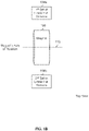
- Figure 1B is a diagram illustrating an embodiment of a servo sensor with two sets of linear Hall sensors from a top view.
- the viewer is looking down on the magnet and the linear Hall sensors, with the magnet closer to the viewer.
- neither set of linear Hall sensors (102a and 102b) lie in the magnet's axis of rotation (110).
- Figure 1A and Figure 1B shows that the two sets of linear Hall sensors are in separate ICs and therefore the exemplary servo sensor is not vulnerable to common mode failures. For example, if the first IC with the first set of linear Hall sensors lost power, the second IC does not automatically or necessarily lose power as well. This offers an improvement over measurement technique where all of the linear Hall sensors are in the same component.
- FIG. 2 is a diagram illustrating another type of servo sensor which is more vulnerable to common mode failure.
- a magnet 200
- An output shaft (not shown).
- An IC 202
- linear Hall sensors are used to measure the angle of the magnet. In order to do so, all of the linear Hall sensors are expected to lie in the magnet's axis of rotation (204) and have the same distance from the magnet.
- Above the magnet (not shown) is the output shaft to which the magnet is coupled. Therefore, a second, hypothetical IC (not shown) with linear Hall sensors cannot be placed above the magnet. The second IC also cannot be placed below the magnet at the same distance as the IC shown, because then two ICs would occupy the same point in space, which is not possible. It is therefore not easy to separate linear Hall sensors into multiple packages or components with other angle measurement techniques.
- the design shown in Figure 2 also places more constraints on the placement or layout of components, which may make the overall design larger.
- arrangement shown in Figure 1A and Figure 1B makes the layout or design of the system easier and/or the layout or design can be better optimized so that the overall volume or size of the servo sensor is smaller.
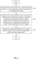
- Figure 3 is a flowchart illustrating an embodiment of a process to estimate an angle using two or more sets of linear Hall sensors.
- the method is performed by an aircraft (e.g., a fly-by-wire aircraft) which uses servos to move aerodynamic control surfaces of the airplane. This method may be used to measure the angle of such servos so that the measured angle can be compared against some desired angle (e.g., in a feedback loop in the servo system).
- the process is performed using the system shown in Figure 1A and Figure 1B .
- a first measurement of a magnet that rotates is received from a first set of one or more linear Hall sensors in a first component.
- the measurement H1 from Figure 1A is one example of a first measurement that may be received at step 300 and the first IC which holds the first set of linear Hall sensors (104a) is one example of a first set of one or more linear Hall sensors and/or a first component from which such a measurement is received.
- a second measurement associated with the magnet is received from a second set of one or more linear Hall sensors in a second component, wherein the first component and the second component are in a plane that is parallel to an axis of rotation associated with the magnet.
- H2 is received from the second IC which includes the second set of linear Hall sensors (104b).
- Figure 1A also shows that the two ICs (or, more generally, components) are in plane 106 which is parallel to the magnet's axis of rotation.
- an angle associated with the magnet is estimated based at least in part on the first measurement and the second measurement. For example, in the above equation, the H1 and H2 values are input to an atan2 function and the output of the atan2 function is the estimated or measured angle.
- measurements from three or more components is used to determine the angle associated with the magnet.
- the following figure shows one such example.
- Figure 4 is a diagram illustrating an embodiment of a servo sensor with three sets of linear Hall sensors.
- a first set of linear Hall sensors is in a first IC (402a)
- a second set of linear Hall sensors is in a second IC (402b)
- a third set of linear Hall sensors is in a third IC (402c).
- the three ICs output measured values of H1, H2, and H3, respectively.
- the angle formed by the first IC (402a), the magnet (400), and the third IC (402c) in this figure is ⁇ /3 whereas in Figure 1A this angle is ⁇ /4.
- the ICs (402a - 402c) are in a plane (406) which is parallel to the magnet's axis of rotation (e.g., coming out of the page at the center of magnet 400).
- the following figure shows one example of a PCB with three ICs (containing three sets of linear Hall sensors) mounted to the PCB.
- Figure 5 is a diagram illustrating an embodiment of a PCB with three ICs with linear Hall sensors.
- diagram 500 shows a top view of a PCB (502) with the three ICs with linear Hall sensors (504) mounted to the PCB.
- the magnet and output shaft for which an angle is measured is not shown.
- Diagram 510 shows a side view of the same PCB (502) with additional components which are not shown in diagram 500.
- the output shaft (512) rotates per the instructions of the servo and the rotation of the output shaft causes a magnet (514) attached to the output shaft to similarly rotate.
- a magnet 514
- the three ICs with the linear Hall sensors (504) which are attached to PCB 502. It is noted that in diagram 510 the ICs are not visible because they are blocked by a screw or bolt.
- the arrangement of linear Hall sensors described herein permits less expensive packaging.
- the output shaft (512) is parallel to PCB 502 and this may permit the overall size of the servo system to be smaller, which makes the system to be less expensive.
- the second IC (402b) is located closer to the magnet (400) compared to the first IC (402a) and the third IC (402c). This causes the H2 signal to have a larger amplitude compared to the H1 signal and H3 signal.
- the following figure shows an example of the H1, H2, and H3 signals as a function of the magnet's angle.
- Figure 6 is a graph illustrating an embodiment of values measured by three sets of linear Hall sensors as a function of angle.
- the x-axis of the graph is the angle of the magnet in degrees (e.g., ⁇ in Figure 4 ) and the y-axis is the measured value (proportional to the magnetic field, B) output by a particular IC or set of linear Hall sensors (e.g., 402a - 402c in Figure 4 ).
- Signal 600 shows the H1 measured values output by a first IC (e.g., 402a in Figure 4 ), signal 602 shows the H2 measured values output by a second IC (e.g., 402b in Figure 4 ), and signal 604 shows the H3 measured values output by a third IC (e.g., 402c in Figure 4 ).
- the signals have a phase difference of -120°.
- FIG. 7 is a block diagram of a system which uses three sets of linear Hall sensors to measure an angle and monitoring the health of the system.
- a Clarke transform 700 inputs the three measured values of H1, H2, and H3 after scaling to account for the different amplitudes.
- the H1 - H3 signals input by the Clarke transform should be sin ⁇ + 2 ⁇ 3 , sin( ⁇ ), and sin ⁇ + 4 ⁇ 3 , respectively, if all of the linear Hall sensors are working properly.
- the differences in amplitude shown in Figure 6 may be handled before the H1 - H3 signals are input to the Clarke transformation, for example by using a different part number for the middle IC (e.g., 402b in Figure 4 ) compared to the outer ICs (e.g., 402a and 402c in Figure 4 ) so that the amplitudes of the outputs of the ICs mostly or substantially match (using different part numbers also helps with the signal to noise ratio). Any residual scale factor imbalance can be accounted for in software with calibration factors after the signals have been digitized with an analog-to-digital converter (ADC).
- ADC analog-to-digital converter
- the Clarke transform (also known as an alpha-beta transform) is a matrix operation that inputs the H1 - H3 values and outputs three values: an alpha (a) value, a beta ( ⁇ ) value, and a gamma (y) value.
- the ⁇ estimate is output and may be used by the system as desired (e.g., in a feedback loop where the estimated or measured angle is compared against some desired angle).
- calibration and/or correction is periodically performed in support of a trigonometric solution to the correction of scale factors (above). For example, such corrections may be used to account for the variability in placement of the sensors, thermal effects on the magnet and/or sensors, local magnetic fields/offsets, etc.
- the system In addition to generating an estimate or measurement of the angle, the system also monitors the health of the system. In this example, two metrics are monitored to generate a health status signal.
- the first metric which is monitored in this example is the gamma value output by the Clarke transform (700). If all of the H1 - H3 values are properly scaled and are properly spaced -120 degrees apart, then the value of gamma will be zero. If gamma becomes (e.g., significantly or meaningfully) non-zero, this indicates an issue with the amplitude and/or phase of one or more of the H1 - H3 signals.
- the gamma value is input to a first comparator (704) where it is compared against a maximum gamma deviation (e.g., the largest amount gamma can deviate from zero before being flagged as a problem). If the gamma value is larger than the maximum gamma deviation, it is an indication that at least one of the ICs may have an issue and the output of comparator 704 becomes a 1 (i.e., a 0 means that the gamma value has not exceeded the maximum gamma deviation).
- a maximum gamma deviation e.g., the largest amount gamma can deviate from zero before being flagged as a problem.
- the second metric which is monitored in this example is the amplitude of the alpha-beta vector.
- the alpha-beta vector is a vector formed by the alpha and beta values output by the Clarke transform. Since alpha and beta are orthogonal to each other, the amplitude of the alpha-beta vector is ⁇ 2 + ⁇ 2 . If the system is working properly, the amplitude of the alpha-beta vector should be constant. To check for this, the alpha and beta values output by the Clarke transform are input to a function (706) which determines the amplitude of the alpha-beta vector. A nominal amplitude is subtracted (708) from the amplitude output by function 706 and the difference is passed to an absolute value function (710).
- the absolute value output by function 710 is input to a second comparator (712) where it is compared against a maximum amplitude deviation. If the absolute value exceeds the maximum amplitude deviation, then the output of the second comparator becomes a 1 (so that a 0 means that the amplitude of the alpha-beta vector has not varied beyond a fixed and/or nominal amplitude to an acceptable degree).
- the outputs of the first comparator (704) and second comparator (712) are passed to an OR gate (714). If either output of the comparators is a 1 (i.e., the corresponding metric being monitored indicates a problem in the system), then the output of the OR gate (which is the health status signal) will also be a 1. If the health status signal is a 0, then the health of the system is good; if the health status signal is a 1, then the health of the system is bad. In the latter case, the system may decide to stop using the ⁇ estimate generating using linear Hall sensors and switch to some other measurement technique (e.g., the one described below which uses discrete Hall sensors).
- the example system may be desirable because health monitoring is performed. Some other systems may not perform health monitoring.
- a trigonometric and/or Clarke transformation-based approach is used. This is merely one solution and in various embodiments some other technique or approach is used.
- simple lookup tables are used (e.g., one for each sensor) along with region constraints which describe or otherwise specify when to use each sensor. For example, given the exemplary 270° spacing above (see, e.g., Figure 6 and regions 610, 612, and 614), about 270° of range can be covered with this approach.
- a reverse lookup can be done on the two sensors not presently in use with simple bound checking on each sensor to determine if there is agreement.
- the initialization routine runs the health monitoring process on each sensor and determines which region the position is presently in by choosing the solution (i.e., region) which reports as "healthy.”
- a 3D look-up table is used at each point on the calibrated triple-Hall Sensor data.
- the construction of the lookup table gives a shallow gradient near the valid solution points and diverge to an invalid value at positions which are not valid (e.g., because one of the sensors disagrees).
- a Kalman filter or other advanced estimator uses some form of covariance scheduling for each sensor based on the present estimation state.
- the health of the system is a product of the estimator as well.
- the secondary position measurement factors into the health solution varies depending upon the solution or approach.
- the secondary position measurement is an additional state for the estimator (e.g., bounding its error).
- the secondary position measurement would be used in a manner similar to the trigonometric approach (e.g., as a gross comparison with an additional "voting" sensor to allow continued operation in the event of a failed Hall sensor).
- Figure 8 is a flowchart illustrating an embodiment of a process to estimate an angle using three or more sets of linear Hall sensors.
- the process shown here is performed in combination with the process of Figure 3 .
- step 800 is an additional step (e.g., in addition to steps 300, 302, and 304) and steps 802 and 804 are part of step 304.
- a third measurement associated with the magnet is received from a third set of one or more linear Hall sensors in a third component, wherein the third component is in the same plane as the first component and the second component. See, for example, Figure 4 where there are three ICs (402a - 402c) with three sets of linear Hall sensors.
- one of the ICs e.g., the one closest to the magnet
- an alpha value, a beta value, and a gamma value are generated using a Clarke transform, the first measurement, the second measurement, and the third measurement. See, for example, Figure 7 where Clarke transform 700 inputs H1 - H3 values and outputs alpha, beta, and gamma values.
- Clarke transform 700 inputs H1 - H3 values and outputs alpha, beta, and gamma values.
- one or more of the H1 - H3 signals are scaled (if or as needed) so that the signals have the same magnitude.
- different part numbers or component types are used so that the signal output by the IC which is closer to the magnet has the same amplitude as the ICs which are further away.
- the angle associated with the magnet is determined, including by performing an atan2 function on the alpha value and the beta value. See, for example, the atan2 function (702) in Figure 7 , from which ⁇ estimate is obtained.
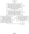
- Figure 9 is a flowchart illustrating an embodiment of a process to generate a health status signal.
- the example process is performed in combination with the process of Figure 3 .
- a third measurement associated with the magnet is received from a third set of one or more linear Hall sensors in a third component, wherein the third component is in the same plane as the first component and the second component. For example, it may be necessary to have at least three sets of linear Hall sensors in order to detect when the health of the system is poor.
- an alpha value, a beta value, and a gamma value are generated using a Clarke transform, the first measurement, the second measurement, and the third measurement. As described above, in some embodiments, steps are taken to ensure that the first measurement, the second measurement, and the third measurement have the sample amplitude before they are input to the Clarke transform.
- a health status signal is generated, including by monitoring an amplitude of an alpha-beta vector, associated with the alpha value and the beta value, for variation from a fixed value using a maximum amplitude deviation.
- the amplitude of the alpha-beta vector should remain constant and variation in the amplitude (e.g., beyond some permitted or acceptable amount) it is indicative of a problem in the system.
- a health status signal is generated, including by monitoring the gamma value for variation from a zero value using a maximum gamma deviation.
- the value of gamma should be zero and if gamma deviates from a zero value (e.g., beyond some permitted or acceptable amount), then it is indicative of a problem in the system.
- steps 904 and 906 are shown together in this figure but it is not necessary for both to be used in the same system
- some embodiments may choose to monitor the amplitude of the alpha-beta vector but not monitor the gamma value, or vice versa.
- both are used in the same system (see, e.g., Figure 7 where the health status signal depends both upon the amplitude of the alpha-beta vector and the gamma value).
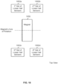
- Figure 10 is a diagram illustrating an embodiment of a servo sensor with four sets of linear Hall sensors.
- the four sets of linear Hall sensors (1002a- 1002b) are used to measure the angle of the magnet (1000) and monitor the health of the system.
- ⁇ 13 and ⁇ 24 are compared and the angle estimate is based on the discrete Hall sensors. If all of them fall within some tolerance band of each other, then the angle estimate is the average of ⁇ 13 and ⁇ 24 (e.g., because these are more accurate than the discrete estimate and the average should be better than either by itself). If the three estimates vary from each other by more than some threshold, then median voting is used. That is, whatever value is in the middle is chosen as the angle estimate.
- FIG 11 is a diagram illustrating an embodiment of a motor with discrete Hall sensors which are used to measure the angle of an output shaft.
- Diagram 1100 shows a side view of the system.
- the motor shaft (1104) is associated with a brushless three phase motor.
- Brushless motors have stationary windings that act against permanent magnets in the rotating part of the motor.
- the motor has three discrete Hall sensors that are used to measure the angle of the rotor in the motor shaft to within one of six sectors (e.g., where each sector is shaped like a slice of pie and in this example a sector has an angle of 60 degrees). With a brushed motor, discrete Hall sensors would not be used (e.g., because brushes are used instead).
- Diagram 1110 shows a table with the outputs of each of the discrete Hall sensors and the corresponding position of the rotor in the motor shaft indicated by that particular combination of discrete Hall sensor output values.
- the number of discrete Hall sensors in this example, three
- the angle of each sector in this example, 60 degrees
- the techniques work other values.
- one benefit of this technique is that the discrete Hall sensors are included in the system anyway (e.g., they are part of the brushless motor) and so no additional sensors need to be used in order to measure the angle of the output shaft. By reusing an existing component, the size, weight, and cost of the system can be kept down.
- the output shaft (1102) is coupled to the motor shaft (1104) via a set of gears (1106).
- the following figure shows other enumerated examples of positions of a rotor in a motor shaft and corresponding angles of an output shaft.
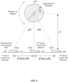
- Figure 12 is a diagram illustrating an embodiment of related positions of a rotor in a motor shaft and angles of an output shaft.
- the left column shows the position of the rotor and the right column shows the angle of the output shaft.
- knowledge of the current rotor position alone is not sufficient to determine the current output shaft angle. For example, even if it is known that the current rotor position is sector 2, it is not known whether the current output shaft angle should be 1 ⁇ 3 degree (see row 1202), 21 ⁇ 3 degrees (see row 1204), 41 ⁇ 3 degrees (see row 1206), etc.
- this angle measurement technique relies upon incrementing or decrementing a previous output shaft angle based on what direction the rotor moved (that is, this is an incremental technique). Note, for example, that all of the output shaft angles in the right column have a difference of 1 ⁇ 3 degree. If the rotor shifts one sector down (e.g., from sector 2 to sector 1, from sector 3 to sector 2, etc.), then the output shaft angle goes down by 1 ⁇ 3 degree. If the rotor shifts one sector up (e.g., from sector 1 to sector 2, from sector 2 to sector 3, etc.), then the output shaft angle increases by 1 ⁇ 3 degree.
- Previous state information including the previous rotor position and the previous output shaft angle, is kept.
- the previous rotor position is kept so that the system knows whether the rotor rotated in one direction (e.g., shifted up a sector) versus another direction (e.g., shifted down a sector) and thus whether to increment or decrement the previous output shaft angle by the incremental amount.
- the system only knew the current rotor position (e.g., sector 2) but not the previous sector position (e.g., it didn't know whether the rotor was previously in sector 1 or sector 3), then the rotor's direction of movement would not be known and the system would not know whether to increment or decrement the previous output shaft angle by the incremental amount.
- the output shaft angle is initialized to some known value. Once the initial value (e.g., x 0 ) is known, subsequent values (e.g., x 1 , x 2 , x 3 , ...) can be determined. In this example, if the output shaft angle is known, the rotor position is also known (see the table shown here) and so in this example it is not necessary for the output shaft angle to (e.g., separately or additionally) be initialized to a known value. Naturally, in embodiments where the rotor position cannot be determined from the output shaft angle (e.g., alone), the rotor position can also be initialized to some known value.
- initialization to a known value is performed by driving or moving a servo to a known position using a mechanical stop.
- the position of the rotor and/or angle of the output shaft may be initialized to known values using the measurement from the primary or initial measurement technique (e.g., using linear Hall sensors as described above).
- the latter technique is desirable because it permits the angle of an output shaft to be initialized to a known value without requiring the output shaft to move.
- aerodynamic control surfaces of an aircraft are controlled by the output shaft of a servo and the output shaft cannot always change to an arbitrary position because this may cause the aircraft to crash during flight.
- this angle measurement technique yields an acceptable resolution because of two characteristics associated with the gears (1106).
- the gear has a high gear reduction (in this example, 180:1). That is, not only do the gears reduce the number of rotations translated from the motor shaft (1104) to the output shaft (1102), but that ratio is relatively high.
- the gears have low backlash (in this example, 1 ⁇ 4 degree). Both the gear ratio and the backlash affect the resolution of this angle estimation technique.
- Figure 13 is a flowchart illustrating an embodiment of a process to estimate an angle using a plurality of discrete Hall sensors.
- this technique is used as a backup angle measurement technique (e.g., if the linear Hall sensor based technique described above fails). It is noted that having the backup angle measurement technique rely upon a different set of sensors compared to the primary angle measurement technique is attractive for reliability reasons (e.g., the discrete Hall sensors may still be working even if the linear Hall sensors are not working). Alternatively, this technique may be used as a primary angle measurement technique (e.g., not in combination with the linear Hall sensor based technique described above).
- At 1300 at least an output shaft angle associated with an output shaft is initialized to a known value, wherein the output shaft is coupled to a motor shaft via a set of one or more gears.
- the output shaft angle is initialized to a value of 0 degrees (corresponding to row 1200).
- some other angle measurement technique provides its estimate or measurement of the output shaft angle as the known value during initialization.
- the rotor position is also initialized to a known value.
- a direction of rotation associated with the motor shaft is determined using a plurality of discrete Hall sensors in the motor.
- the directions of rotation of may be either a first direction (e.g., a rotor in the motor shaft goes up a sector or rotates clockwise) or a second direction (e.g., the rotor in the motor shaft goes down a sector or rotates counterclockwise).
- the output shaft angle is updated using an incremental value and the direction of rotation.
- the incremental value is 1 ⁇ 3 degree. If the rotor in that example moves up as sector, the output shaft angle is updated by adding 1 ⁇ 3 degree; if the rotor goes down a sector, the output shaft angle is updated by subtracting 1 ⁇ 3 degree.
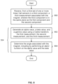
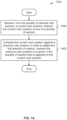
- Figure 14 is a flowchart illustrating an embodiment of a process to determine a direction of rotation associated with the motor shaft.
- step 1302 in Figure 13 includes the process shown.
- a current rotor position is received from the plurality of discrete Hall sensors, wherein the current rotor position is one of a plurality of sectors. See, for example, table 1110 in Figure 11 which shows what combination of discrete Hall sensor outputs correspond to what sector.
- the current rotor position is compared against a previous rotor position in order to determine the direction of rotation, wherein the previous rotor position is a sector in the plurality of sectors that is adjacent to the current rotor position.
- the rotor cannot skip over sectors and so the previous rotor position (i.e., the previous sector) and the current rotor position (i.e., the current sector) are adjacent to each other.
- the two directions of rotation may generally be referred to as a first and second direction.
- Figure 15 is a flowchart illustrating an embodiment of a process to update an output shaft angle using an incremental value and a direction of rotation associated with a motor shaft.
- step 1304 in Figure 13 includes the process shown.
- the direction of rotation is evaluated.
- a previous output shaft angle is increment with the incremental value in order to obtain a current output shaft angle at 1502.
- the incremental value is 1 ⁇ 3 degree and moving up a sector causes the incremental value to be added to the previous output shaft angle.
- the previous output shaft angle is decremented with the incremental value in order to obtain the current output shaft angle at 1504.
- the (previous) output shaft angle is decremented when the rotor goes down a sector.
Landscapes
- Physics & Mathematics (AREA)
- General Physics & Mathematics (AREA)
- Engineering & Computer Science (AREA)
- Technology Law (AREA)
- Transmission And Conversion Of Sensor Element Output (AREA)
- Measurement Of Length, Angles, Or The Like Using Electric Or Magnetic Means (AREA)
- Control Of Multiple Motors (AREA)
Applications Claiming Priority (3)
| Application Number | Priority Date | Filing Date | Title |
|---|---|---|---|
| US15/421,038 US10036654B1 (en) | 2017-01-31 | 2017-01-31 | Fault tolerant servo sensor with linear hall sensors and discrete hall sensors |
| PCT/US2017/015966 WO2018143973A1 (fr) | 2017-01-31 | 2017-02-01 | Capteur asservi à tolérance aux pannes avec capteurs à effet hall et capteurs à effet hall discrets |
| EP17895244.6A EP3577478B1 (fr) | 2017-01-31 | 2017-02-01 | Capteur asservi à tolérance aux pannes avec capteurs à effet hall et capteurs à effet hall discrets |
Related Parent Applications (2)
| Application Number | Title | Priority Date | Filing Date |
|---|---|---|---|
| EP17895244.6A Division EP3577478B1 (fr) | 2017-01-31 | 2017-02-01 | Capteur asservi à tolérance aux pannes avec capteurs à effet hall et capteurs à effet hall discrets |
| EP17895244.6A Division-Into EP3577478B1 (fr) | 2017-01-31 | 2017-02-01 | Capteur asservi à tolérance aux pannes avec capteurs à effet hall et capteurs à effet hall discrets |
Publications (2)
| Publication Number | Publication Date |
|---|---|
| EP4148430A1 true EP4148430A1 (fr) | 2023-03-15 |
| EP4148430B1 EP4148430B1 (fr) | 2026-05-06 |
Family
ID=62948445
Family Applications (2)
| Application Number | Title | Priority Date | Filing Date |
|---|---|---|---|
| EP22205412.4A Active EP4148430B1 (fr) | 2017-01-31 | 2017-02-01 | Servo-capteur insensible aux défaillances avec capteurs à effet hall linéaires et capteurs à effet hall discrets |
| EP17895244.6A Active EP3577478B1 (fr) | 2017-01-31 | 2017-02-01 | Capteur asservi à tolérance aux pannes avec capteurs à effet hall et capteurs à effet hall discrets |
Family Applications After (1)
| Application Number | Title | Priority Date | Filing Date |
|---|---|---|---|
| EP17895244.6A Active EP3577478B1 (fr) | 2017-01-31 | 2017-02-01 | Capteur asservi à tolérance aux pannes avec capteurs à effet hall et capteurs à effet hall discrets |
Country Status (4)
| Country | Link |
|---|---|
| US (3) | US10036654B1 (fr) |
| EP (2) | EP4148430B1 (fr) |
| CN (1) | CN110199201B (fr) |
| WO (1) | WO2018143973A1 (fr) |
Families Citing this family (6)
| Publication number | Priority date | Publication date | Assignee | Title |
|---|---|---|---|---|
| US10036654B1 (en) | 2017-01-31 | 2018-07-31 | Kitty Hawk Corporation | Fault tolerant servo sensor with linear hall sensors and discrete hall sensors |
| CN110022113B (zh) * | 2019-05-21 | 2020-11-06 | 中国科学院宁波材料技术与工程研究所 | 一种永磁同步直线电机的伺服控制方法 |
| CN110739887A (zh) * | 2019-10-12 | 2020-01-31 | 江苏科技大学 | 无刷直流电机单相霍尔故障的容错控制方法及系统 |
| EP3855257A1 (fr) * | 2020-01-22 | 2021-07-28 | Siemens Aktiengesellschaft | Procédé de surveillance d'une fonction protégée contre les erreurs de capteurs dans un moteur |
| US11573075B1 (en) * | 2021-09-16 | 2023-02-07 | Beta Air, Llc | Systems and methods for estimating angular position |
| DE102023209253A1 (de) * | 2023-09-22 | 2025-03-27 | Zf Friedrichshafen Ag | Sensoreinheit und Verfahren zur Bestimmung einer Drehung zumindest einer Welle und einem Rohr, in dem die Welle angeordnet ist |
Citations (4)
| Publication number | Priority date | Publication date | Assignee | Title |
|---|---|---|---|---|
| DE102004061405A1 (de) * | 2004-12-21 | 2006-07-06 | Robert Bosch Gmbh | Kraftfahrzeug sowie Verfahren zu dessen Betrieb |
| US20090140731A1 (en) * | 2005-10-18 | 2009-06-04 | Kunio Miyashita | Multiple-Rotation Absolute-Value Encoder of Geared Motor |
| US20100052663A1 (en) * | 2008-08-30 | 2010-03-04 | Walter Mehnert | Sensor unit for a rotary encoder and a rotary encoder equipped with such a sensor unit |
| DE102014113493A1 (de) * | 2014-09-18 | 2016-03-24 | Jungheinrich Aktiengesellschaft | Flurförderzeug mit einem Lenkwinkelsensor |
Family Cites Families (21)
| Publication number | Priority date | Publication date | Assignee | Title |
|---|---|---|---|---|
| ES2040948T3 (es) * | 1989-08-11 | 1993-11-01 | Siemens Aktiengesellschaft | Dispositivo de reconocimiento del giro. |
| US7307415B2 (en) * | 2002-02-14 | 2007-12-11 | Bvr Technologies Co. | Contactless angular position sensor and method for sensing angular position of a rotatable shaft |
| ATE538017T1 (de) * | 2002-04-15 | 2012-01-15 | Nsk Ltd | Elektrische servolenkvorrichtung |
| EP1499901A2 (fr) * | 2002-04-18 | 2005-01-26 | Continental Teves AG & Co. oHG | Procede et dispositif pour la detection de deplacements locaux et de rotations |
| US7021587B1 (en) | 2004-01-07 | 2006-04-04 | Trutrak Flight Systems, Inc | Dual channel fail-safe system and method for adjusting aircraft trim |
| US7477052B2 (en) * | 2005-03-14 | 2009-01-13 | Continental Automotive Systems Us, Inc. | Two-pole magnet wheel increment position sensing in an actuator |
| US7462999B2 (en) * | 2006-03-29 | 2008-12-09 | Mitchell Electronics, Inc | Brushless servo motor tester |
| FR2902872B1 (fr) * | 2006-06-27 | 2008-11-14 | Arvinmeritor Light Vehicle Sys | Dispositif de mesure de champ magnetique. |
| WO2008050578A1 (fr) * | 2006-10-27 | 2008-05-02 | The Furukawa Electric Co., Ltd. | Dispositif de détection de l'angle de rotation et procédé de détection de l'angle de rotation |
| US8575941B2 (en) * | 2009-09-08 | 2013-11-05 | Schweitzer Engineering Laboratories Inc | Apparatus and method for identifying a faulted phase in a shunt capacitor bank |
| JP5067676B2 (ja) * | 2010-03-12 | 2012-11-07 | 株式会社デンソー | センサユニット及び、集磁モジュール |
| DE102012212272A1 (de) | 2012-07-13 | 2014-01-16 | Robert Bosch Gmbh | Hall-Sensor |
| US9219432B2 (en) | 2012-07-25 | 2015-12-22 | System General Corporation | Control systems and methods for angle estimation of permanent magnet motors |
| EP2706326B1 (fr) | 2012-09-07 | 2015-12-16 | ams AG | Système de capteur, système de commande de direction et procédé pour déterminer un angle de rotation |
| JP6163874B2 (ja) * | 2013-05-23 | 2017-07-19 | 株式会社リコー | 回転角度検出装置、画像処理装置及び回転角度検出方法 |
| FR3006706B1 (fr) * | 2013-06-06 | 2015-06-05 | Somfy Sas | Detection de la position d’un tambour d’enroulement accouple a un moteur par l’intermediaire d’un element souple amortisseur |
| US9982989B2 (en) * | 2013-07-17 | 2018-05-29 | Infineon Technologies Ag | Angle sensors, systems and methods |
| JP6455111B2 (ja) * | 2014-12-05 | 2019-01-23 | 株式会社ジェイテクト | 回転角検出装置 |
| US10135369B2 (en) * | 2015-09-29 | 2018-11-20 | Microchip Technology Incorporated | Linear hall effect sensors for multi-phase permanent magnet motors with PWM drive |
| JP6622056B2 (ja) * | 2015-10-23 | 2019-12-18 | 日本電子株式会社 | 検出装置および荷電粒子線装置 |
| US10036654B1 (en) | 2017-01-31 | 2018-07-31 | Kitty Hawk Corporation | Fault tolerant servo sensor with linear hall sensors and discrete hall sensors |
-
2017
- 2017-01-31 US US15/421,038 patent/US10036654B1/en active Active
- 2017-02-01 EP EP22205412.4A patent/EP4148430B1/fr active Active
- 2017-02-01 CN CN201780084807.XA patent/CN110199201B/zh active Active
- 2017-02-01 WO PCT/US2017/015966 patent/WO2018143973A1/fr not_active Ceased
- 2017-02-01 EP EP17895244.6A patent/EP3577478B1/fr active Active
-
2018
- 2018-06-08 US US16/004,224 patent/US10859401B2/en active Active
-
2020
- 2020-09-15 US US17/021,783 patent/US11280638B2/en active Active
Patent Citations (4)
| Publication number | Priority date | Publication date | Assignee | Title |
|---|---|---|---|---|
| DE102004061405A1 (de) * | 2004-12-21 | 2006-07-06 | Robert Bosch Gmbh | Kraftfahrzeug sowie Verfahren zu dessen Betrieb |
| US20090140731A1 (en) * | 2005-10-18 | 2009-06-04 | Kunio Miyashita | Multiple-Rotation Absolute-Value Encoder of Geared Motor |
| US20100052663A1 (en) * | 2008-08-30 | 2010-03-04 | Walter Mehnert | Sensor unit for a rotary encoder and a rotary encoder equipped with such a sensor unit |
| DE102014113493A1 (de) * | 2014-09-18 | 2016-03-24 | Jungheinrich Aktiengesellschaft | Flurförderzeug mit einem Lenkwinkelsensor |
Also Published As
| Publication number | Publication date |
|---|---|
| US20210055133A1 (en) | 2021-02-25 |
| US20180292234A1 (en) | 2018-10-11 |
| NZ768202A (en) | 2024-01-26 |
| US11280638B2 (en) | 2022-03-22 |
| WO2018143973A1 (fr) | 2018-08-09 |
| NZ755102A (en) | 2021-03-26 |
| US20180216964A1 (en) | 2018-08-02 |
| US10859401B2 (en) | 2020-12-08 |
| EP4148430B1 (fr) | 2026-05-06 |
| EP3577478A4 (fr) | 2020-11-04 |
| EP3577478A1 (fr) | 2019-12-11 |
| CN110199201A (zh) | 2019-09-03 |
| CN110199201B (zh) | 2022-04-01 |
| US10036654B1 (en) | 2018-07-31 |
| EP3577478B1 (fr) | 2022-12-21 |
Similar Documents
| Publication | Publication Date | Title |
|---|---|---|
| US11280638B2 (en) | Fault tolerant servo sensor with linear hall sensors and discrete hall sensors | |
| US20250362359A1 (en) | Magnetic position sensor system and method | |
| EP3469383B1 (fr) | Capteur de champ magnétique à correction d'erreur | |
| US10132649B2 (en) | Apparatus and method for the redundant, absolute position determination of a movable body | |
| US10670383B2 (en) | Calibrating and operating rotary devices, in particular for rotating probe heads and/or probes of coordinate measuring machines | |
| US8933692B2 (en) | Rotation angle detection device | |
| EP4325238B1 (fr) | Capteur de champ magnétique avec correction d'erreur d'alignement | |
| EP4056956B1 (fr) | Système et procédé de capteur de position, solides contre les champs de perturbation | |
| US10281299B2 (en) | Angle sensor, a bearing unit, electrical motor, a control system and error-check system | |
| US20170030742A1 (en) | Correction apparatus and method for angle sensor, and angle sensor | |
| US11774234B2 (en) | Angle sensor calibration method for safety measure without full rotation | |
| US20200400463A1 (en) | Rotation angle sensor, angle signal calculation method and non-transitory computer readable medium | |
| WO2008053581A1 (fr) | Capteur de rotation et palier équipé dudit capteur de rotation | |
| US12215973B2 (en) | Magnetic-field-based angle sensor system with stray field compensation and method for stray field compensation | |
| US11500038B2 (en) | Sensor, control device and method for determining the direction of a magnetic field | |
| EP3957959B1 (fr) | Dispositif de détection d'angle | |
| NZ755102B2 (en) | Fault tolerant servo sensor with linear hall sensors and discrete hall sensors | |
| Khattab et al. | A Novel method for online correction of amplitude and phase imbalances in sinusoidal encoders signals | |
| EP4184122B1 (fr) | Capteur magnétique de position angulaire | |
| US20250060209A1 (en) | Method for compensating angular errors | |
| US9846057B2 (en) | Method and apparatus for computing an angle of rotation | |
| CN120538403A (zh) | 高精度角度测量系统 | |
| JP2006125853A (ja) | 位置検出方式 |
Legal Events
| Date | Code | Title | Description |
|---|---|---|---|
| PUAI | Public reference made under article 153(3) epc to a published international application that has entered the european phase |
Free format text: ORIGINAL CODE: 0009012 |
|
| STAA | Information on the status of an ep patent application or granted ep patent |
Free format text: STATUS: THE APPLICATION HAS BEEN PUBLISHED |
|
| AC | Divisional application: reference to earlier application |
Ref document number: 3577478 Country of ref document: EP Kind code of ref document: P |
|
| AK | Designated contracting states |
Kind code of ref document: A1 Designated state(s): AL AT BE BG CH CY CZ DE DK EE ES FI FR GB GR HR HU IE IS IT LI LT LU LV MC MK MT NL NO PL PT RO RS SE SI SK SM TR |
|
| P01 | Opt-out of the competence of the unified patent court (upc) registered |
Effective date: 20230507 |
|
| STAA | Information on the status of an ep patent application or granted ep patent |
Free format text: STATUS: REQUEST FOR EXAMINATION WAS MADE |
|
| 17P | Request for examination filed |
Effective date: 20230913 |
|
| RBV | Designated contracting states (corrected) |
Designated state(s): AL AT BE BG CH CY CZ DE DK EE ES FI FR GB GR HR HU IE IS IT LI LT LU LV MC MK MT NL NO PL PT RO RS SE SI SK SM TR |
|
| STAA | Information on the status of an ep patent application or granted ep patent |
Free format text: STATUS: EXAMINATION IS IN PROGRESS |
|
| 17Q | First examination report despatched |
Effective date: 20240301 |
|
| GRAP | Despatch of communication of intention to grant a patent |
Free format text: ORIGINAL CODE: EPIDOSNIGR1 |
|
| STAA | Information on the status of an ep patent application or granted ep patent |
Free format text: STATUS: GRANT OF PATENT IS INTENDED |
|
| INTG | Intention to grant announced |
Effective date: 20251128 |
|
| GRAS | Grant fee paid |
Free format text: ORIGINAL CODE: EPIDOSNIGR3 |
|
| GRAA | (expected) grant |
Free format text: ORIGINAL CODE: 0009210 |
|
| STAA | Information on the status of an ep patent application or granted ep patent |
Free format text: STATUS: THE PATENT HAS BEEN GRANTED |