EP4148433B1 - Strommessvorrichtung - Google Patents
Strommessvorrichtung Download PDFInfo
- Publication number
- EP4148433B1 EP4148433B1 EP21847084.7A EP21847084A EP4148433B1 EP 4148433 B1 EP4148433 B1 EP 4148433B1 EP 21847084 A EP21847084 A EP 21847084A EP 4148433 B1 EP4148433 B1 EP 4148433B1
- Authority
- EP
- European Patent Office
- Prior art keywords
- terminal
- resistor
- current measurement
- measurement apparatus
- extending portion
- Prior art date
- Legal status (The legal status is an assumption and is not a legal conclusion. Google has not performed a legal analysis and makes no representation as to the accuracy of the status listed.)
- Active
Links
Images





Classifications
-
- G—PHYSICS
- G01—MEASURING; TESTING
- G01R—MEASURING ELECTRIC VARIABLES; MEASURING MAGNETIC VARIABLES
- G01R19/00—Arrangements for measuring currents or voltages or for indicating presence or sign thereof
- G01R19/0092—Measuring current only
-
- G—PHYSICS
- G01—MEASURING; TESTING
- G01R—MEASURING ELECTRIC VARIABLES; MEASURING MAGNETIC VARIABLES
- G01R1/00—Details of instruments or arrangements of the types included in groups G01R5/00 - G01R13/00 and G01R31/00
- G01R1/36—Overload-protection arrangements or circuits for electric measuring instruments
-
- H—ELECTRICITY
- H02—GENERATION; CONVERSION OR DISTRIBUTION OF ELECTRIC POWER
- H02H—EMERGENCY PROTECTIVE CIRCUIT ARRANGEMENTS
- H02H1/00—Details of emergency protective circuit arrangements
- H02H1/0007—Details of emergency protective circuit arrangements concerning the detecting means
-
- B—PERFORMING OPERATIONS; TRANSPORTING
- B60—VEHICLES IN GENERAL
- B60L—PROPULSION OF ELECTRICALLY-PROPELLED VEHICLES; SUPPLYING ELECTRIC POWER FOR AUXILIARY EQUIPMENT OF ELECTRICALLY-PROPELLED VEHICLES; ELECTRODYNAMIC BRAKE SYSTEMS FOR VEHICLES IN GENERAL; MAGNETIC SUSPENSION OR LEVITATION FOR VEHICLES; MONITORING OPERATING VARIABLES OF ELECTRICALLY-PROPELLED VEHICLES; ELECTRIC SAFETY DEVICES FOR ELECTRICALLY-PROPELLED VEHICLES
- B60L3/00—Electric devices on electrically-propelled vehicles for safety purposes; Monitoring operating variables, e.g. speed, deceleration or energy consumption
- B60L3/0023—Detecting, eliminating, remedying or compensating for drive train abnormalities, e.g. failures within the drive train
- B60L3/0046—Detecting, eliminating, remedying or compensating for drive train abnormalities, e.g. failures within the drive train relating to electric energy storage systems, e.g. batteries or capacitors
-
- B—PERFORMING OPERATIONS; TRANSPORTING
- B60—VEHICLES IN GENERAL
- B60L—PROPULSION OF ELECTRICALLY-PROPELLED VEHICLES; SUPPLYING ELECTRIC POWER FOR AUXILIARY EQUIPMENT OF ELECTRICALLY-PROPELLED VEHICLES; ELECTRODYNAMIC BRAKE SYSTEMS FOR VEHICLES IN GENERAL; MAGNETIC SUSPENSION OR LEVITATION FOR VEHICLES; MONITORING OPERATING VARIABLES OF ELECTRICALLY-PROPELLED VEHICLES; ELECTRIC SAFETY DEVICES FOR ELECTRICALLY-PROPELLED VEHICLES
- B60L58/00—Methods or circuit arrangements for monitoring or controlling batteries or fuel cells, specially adapted for electric vehicles
- B60L58/10—Methods or circuit arrangements for monitoring or controlling batteries or fuel cells, specially adapted for electric vehicles for monitoring or controlling batteries
-
- G—PHYSICS
- G01—MEASURING; TESTING
- G01R—MEASURING ELECTRIC VARIABLES; MEASURING MAGNETIC VARIABLES
- G01R19/00—Arrangements for measuring currents or voltages or for indicating presence or sign thereof
- G01R19/0046—Arrangements for measuring currents or voltages or for indicating presence or sign thereof characterised by a specific application or detail not covered by any other subgroup of G01R19/00
-
- G—PHYSICS
- G01—MEASURING; TESTING
- G01R—MEASURING ELECTRIC VARIABLES; MEASURING MAGNETIC VARIABLES
- G01R27/00—Arrangements for measuring resistance, reactance, impedance, or electric characteristics derived therefrom
- G01R27/02—Measuring real or complex resistance, reactance, impedance, or other two-pole characteristics derived therefrom, e.g. time constant
-
- G—PHYSICS
- G01—MEASURING; TESTING
- G01R—MEASURING ELECTRIC VARIABLES; MEASURING MAGNETIC VARIABLES
- G01R27/00—Arrangements for measuring resistance, reactance, impedance, or electric characteristics derived therefrom
- G01R27/02—Measuring real or complex resistance, reactance, impedance, or other two-pole characteristics derived therefrom, e.g. time constant
- G01R27/14—Measuring resistance by measuring current or voltage obtained from a reference source
-
- G—PHYSICS
- G01—MEASURING; TESTING
- G01R—MEASURING ELECTRIC VARIABLES; MEASURING MAGNETIC VARIABLES
- G01R3/00—Apparatus or processes specially adapted for the manufacture or maintenance of measuring instruments, e.g. of probe tips
-
- G—PHYSICS
- G01—MEASURING; TESTING
- G01R—MEASURING ELECTRIC VARIABLES; MEASURING MAGNETIC VARIABLES
- G01R31/00—Arrangements for testing electric properties; Arrangements for locating electric faults; Arrangements for electrical testing characterised by what is being tested not provided for elsewhere
- G01R31/36—Arrangements for testing, measuring or monitoring the electrical condition of accumulators or electric batteries, e.g. capacity or state of charge [SoC]
- G01R31/374—Arrangements for testing, measuring or monitoring the electrical condition of accumulators or electric batteries, e.g. capacity or state of charge [SoC] with means for correcting the measurement for temperature or ageing
-
- G—PHYSICS
- G01—MEASURING; TESTING
- G01R—MEASURING ELECTRIC VARIABLES; MEASURING MAGNETIC VARIABLES
- G01R31/00—Arrangements for testing electric properties; Arrangements for locating electric faults; Arrangements for electrical testing characterised by what is being tested not provided for elsewhere
- G01R31/36—Arrangements for testing, measuring or monitoring the electrical condition of accumulators or electric batteries, e.g. capacity or state of charge [SoC]
- G01R31/382—Arrangements for monitoring battery or accumulator variables, e.g. SoC
- G01R31/3835—Arrangements for monitoring battery or accumulator variables, e.g. SoC involving only voltage measurements
-
- G—PHYSICS
- G01—MEASURING; TESTING
- G01R—MEASURING ELECTRIC VARIABLES; MEASURING MAGNETIC VARIABLES
- G01R31/00—Arrangements for testing electric properties; Arrangements for locating electric faults; Arrangements for electrical testing characterised by what is being tested not provided for elsewhere
- G01R31/36—Arrangements for testing, measuring or monitoring the electrical condition of accumulators or electric batteries, e.g. capacity or state of charge [SoC]
- G01R31/382—Arrangements for monitoring battery or accumulator variables, e.g. SoC
- G01R31/3842—Arrangements for monitoring battery or accumulator variables, e.g. SoC combining voltage and current measurements
-
- G—PHYSICS
- G01—MEASURING; TESTING
- G01R—MEASURING ELECTRIC VARIABLES; MEASURING MAGNETIC VARIABLES
- G01R31/00—Arrangements for testing electric properties; Arrangements for locating electric faults; Arrangements for electrical testing characterised by what is being tested not provided for elsewhere
- G01R31/36—Arrangements for testing, measuring or monitoring the electrical condition of accumulators or electric batteries, e.g. capacity or state of charge [SoC]
- G01R31/385—Arrangements for measuring battery or accumulator variables
-
- H—ELECTRICITY
- H01—ELECTRIC ELEMENTS
- H01H—ELECTRIC SWITCHES; RELAYS; SELECTORS; EMERGENCY PROTECTIVE DEVICES
- H01H39/00—Switching devices actuated by an explosion produced within the device and initiated by an electric current
- H01H39/006—Opening by severing a conductor
-
- H—ELECTRICITY
- H01—ELECTRIC ELEMENTS
- H01M—PROCESSES OR MEANS, e.g. BATTERIES, FOR THE DIRECT CONVERSION OF CHEMICAL ENERGY INTO ELECTRICAL ENERGY
- H01M10/00—Secondary cells; Manufacture thereof
- H01M10/42—Methods or arrangements for servicing or maintenance of secondary cells or secondary half-cells
-
- H—ELECTRICITY
- H01—ELECTRIC ELEMENTS
- H01M—PROCESSES OR MEANS, e.g. BATTERIES, FOR THE DIRECT CONVERSION OF CHEMICAL ENERGY INTO ELECTRICAL ENERGY
- H01M10/00—Secondary cells; Manufacture thereof
- H01M10/42—Methods or arrangements for servicing or maintenance of secondary cells or secondary half-cells
- H01M10/425—Structural combination with electronic components, e.g. electronic circuits integrated to the outside of the casing
-
- H—ELECTRICITY
- H01—ELECTRIC ELEMENTS
- H01M—PROCESSES OR MEANS, e.g. BATTERIES, FOR THE DIRECT CONVERSION OF CHEMICAL ENERGY INTO ELECTRICAL ENERGY
- H01M10/00—Secondary cells; Manufacture thereof
- H01M10/42—Methods or arrangements for servicing or maintenance of secondary cells or secondary half-cells
- H01M10/48—Accumulators combined with arrangements for measuring, testing or indicating the condition of cells, e.g. the level or density of the electrolyte
-
- H—ELECTRICITY
- H01—ELECTRIC ELEMENTS
- H01M—PROCESSES OR MEANS, e.g. BATTERIES, FOR THE DIRECT CONVERSION OF CHEMICAL ENERGY INTO ELECTRICAL ENERGY
- H01M50/00—Constructional details or processes of manufacture of the non-active parts of electrochemical cells other than fuel cells, e.g. hybrid cells
- H01M50/50—Current conducting connections for cells or batteries
- H01M50/572—Means for preventing undesired use or discharge
- H01M50/574—Devices or arrangements for the interruption of current
- H01M50/583—Devices or arrangements for the interruption of current in response to current, e.g. fuses
-
- H—ELECTRICITY
- H02—GENERATION; CONVERSION OR DISTRIBUTION OF ELECTRIC POWER
- H02H—EMERGENCY PROTECTIVE CIRCUIT ARRANGEMENTS
- H02H7/00—Emergency protective circuit arrangements specially adapted for specific types of electric machines or apparatus or for sectionalised protection of cable or line systems, and effecting automatic switching in the event of an undesired change from normal working conditions
- H02H7/18—Emergency protective circuit arrangements specially adapted for specific types of electric machines or apparatus or for sectionalised protection of cable or line systems, and effecting automatic switching in the event of an undesired change from normal working conditions for batteries; for accumulators
-
- B—PERFORMING OPERATIONS; TRANSPORTING
- B60—VEHICLES IN GENERAL
- B60L—PROPULSION OF ELECTRICALLY-PROPELLED VEHICLES; SUPPLYING ELECTRIC POWER FOR AUXILIARY EQUIPMENT OF ELECTRICALLY-PROPELLED VEHICLES; ELECTRODYNAMIC BRAKE SYSTEMS FOR VEHICLES IN GENERAL; MAGNETIC SUSPENSION OR LEVITATION FOR VEHICLES; MONITORING OPERATING VARIABLES OF ELECTRICALLY-PROPELLED VEHICLES; ELECTRIC SAFETY DEVICES FOR ELECTRICALLY-PROPELLED VEHICLES
- B60L2240/00—Control parameters of input or output; Target parameters
- B60L2240/40—Drive Train control parameters
- B60L2240/54—Drive Train control parameters related to batteries
- B60L2240/549—Current
-
- G—PHYSICS
- G01—MEASURING; TESTING
- G01R—MEASURING ELECTRIC VARIABLES; MEASURING MAGNETIC VARIABLES
- G01R1/00—Details of instruments or arrangements of the types included in groups G01R5/00 - G01R13/00 and G01R31/00
- G01R1/20—Modifications of basic electric elements for use in electric measuring instruments; Structural combinations of such elements with such instruments
- G01R1/203—Resistors used for electric measuring, e.g. decade resistors standards, resistors for comparators, series resistors, shunts
-
- G—PHYSICS
- G01—MEASURING; TESTING
- G01R—MEASURING ELECTRIC VARIABLES; MEASURING MAGNETIC VARIABLES
- G01R19/00—Arrangements for measuring currents or voltages or for indicating presence or sign thereof
- G01R19/165—Indicating that current or voltage is either above or below a predetermined value or within or outside a predetermined range of values
- G01R19/16533—Indicating that current or voltage is either above or below a predetermined value or within or outside a predetermined range of values characterised by the application
- G01R19/16538—Indicating that current or voltage is either above or below a predetermined value or within or outside a predetermined range of values characterised by the application in AC or DC supplies
- G01R19/16542—Indicating that current or voltage is either above or below a predetermined value or within or outside a predetermined range of values characterised by the application in AC or DC supplies for batteries
-
- G—PHYSICS
- G01—MEASURING; TESTING
- G01R—MEASURING ELECTRIC VARIABLES; MEASURING MAGNETIC VARIABLES
- G01R31/00—Arrangements for testing electric properties; Arrangements for locating electric faults; Arrangements for electrical testing characterised by what is being tested not provided for elsewhere
- G01R31/36—Arrangements for testing, measuring or monitoring the electrical condition of accumulators or electric batteries, e.g. capacity or state of charge [SoC]
- G01R31/364—Battery terminal connectors with integrated measuring arrangements
-
- G—PHYSICS
- G01—MEASURING; TESTING
- G01R—MEASURING ELECTRIC VARIABLES; MEASURING MAGNETIC VARIABLES
- G01R31/00—Arrangements for testing electric properties; Arrangements for locating electric faults; Arrangements for electrical testing characterised by what is being tested not provided for elsewhere
- G01R31/36—Arrangements for testing, measuring or monitoring the electrical condition of accumulators or electric batteries, e.g. capacity or state of charge [SoC]
- G01R31/382—Arrangements for monitoring battery or accumulator variables, e.g. SoC
-
- H—ELECTRICITY
- H01—ELECTRIC ELEMENTS
- H01H—ELECTRIC SWITCHES; RELAYS; SELECTORS; EMERGENCY PROTECTIVE DEVICES
- H01H39/00—Switching devices actuated by an explosion produced within the device and initiated by an electric current
- H01H2039/008—Switching devices actuated by an explosion produced within the device and initiated by an electric current using the switch for a battery cutoff
-
- H—ELECTRICITY
- H01—ELECTRIC ELEMENTS
- H01H—ELECTRIC SWITCHES; RELAYS; SELECTORS; EMERGENCY PROTECTIVE DEVICES
- H01H71/00—Details of the protective switches or relays covered by groups H01H73/00 - H01H83/00
- H01H71/10—Operating or release mechanisms
- H01H71/12—Automatic release mechanisms with or without manual release
- H01H71/123—Automatic release mechanisms with or without manual release using a solid-state trip unit
- H01H71/125—Automatic release mechanisms with or without manual release using a solid-state trip unit characterised by sensing elements, e.g. current transformers
-
- H—ELECTRICITY
- H01—ELECTRIC ELEMENTS
- H01H—ELECTRIC SWITCHES; RELAYS; SELECTORS; EMERGENCY PROTECTIVE DEVICES
- H01H9/00—Details of switching devices, not covered by groups H01H1/00 - H01H7/00
- H01H9/52—Cooling of switch parts
-
- H—ELECTRICITY
- H01—ELECTRIC ELEMENTS
- H01M—PROCESSES OR MEANS, e.g. BATTERIES, FOR THE DIRECT CONVERSION OF CHEMICAL ENERGY INTO ELECTRICAL ENERGY
- H01M10/00—Secondary cells; Manufacture thereof
- H01M10/42—Methods or arrangements for servicing or maintenance of secondary cells or secondary half-cells
- H01M10/425—Structural combination with electronic components, e.g. electronic circuits integrated to the outside of the casing
- H01M2010/4271—Battery management systems including electronic circuits, e.g. control of current or voltage to keep battery in healthy state, cell balancing
-
- H—ELECTRICITY
- H01—ELECTRIC ELEMENTS
- H01M—PROCESSES OR MEANS, e.g. BATTERIES, FOR THE DIRECT CONVERSION OF CHEMICAL ENERGY INTO ELECTRICAL ENERGY
- H01M2200/00—Safety devices for primary or secondary batteries
-
- H—ELECTRICITY
- H01—ELECTRIC ELEMENTS
- H01M—PROCESSES OR MEANS, e.g. BATTERIES, FOR THE DIRECT CONVERSION OF CHEMICAL ENERGY INTO ELECTRICAL ENERGY
- H01M2220/00—Batteries for particular applications
- H01M2220/20—Batteries in motive systems, e.g. vehicle, ship, plane
-
- Y—GENERAL TAGGING OF NEW TECHNOLOGICAL DEVELOPMENTS; GENERAL TAGGING OF CROSS-SECTIONAL TECHNOLOGIES SPANNING OVER SEVERAL SECTIONS OF THE IPC; TECHNICAL SUBJECTS COVERED BY FORMER USPC CROSS-REFERENCE ART COLLECTIONS [XRACs] AND DIGESTS
- Y02—TECHNOLOGIES OR APPLICATIONS FOR MITIGATION OR ADAPTATION AGAINST CLIMATE CHANGE
- Y02E—REDUCTION OF GREENHOUSE GAS [GHG] EMISSIONS, RELATED TO ENERGY GENERATION, TRANSMISSION OR DISTRIBUTION
- Y02E60/00—Enabling technologies; Technologies with a potential or indirect contribution to GHG emissions mitigation
- Y02E60/10—Energy storage using batteries
Definitions
- the present disclosure relates to a current measurement apparatus, and more particularly, to a current measurement apparatus configured to quickly block current by itself when an abnormal current flows, and a battery pack and a vehicle including the current measurement apparatus.
- lithium secondary batteries are spotlighted because they ensure free charging and discharging due to substantially no memory effect compared to nickel-based secondary batteries, as well as very low discharge rate and high energy density.
- the lithium secondary battery mainly uses lithium-based oxide and carbon material as positive electrode active material and negative electrode active material, respectively.
- the lithium secondary battery includes an electrode assembly in which a positive electrode plate and a negative electrode plate respectively coated with a positive electrode active material and a negative electrode active material are arranged with a separator interposed therebetween, and an exterior, namely a battery case, for hermetically receiving the electrode assembly together with electrolyte.
- the safety of the battery pack is emerging as a very important issue.
- users of electric vehicles are rapidly increasing, and the failure to secure the safety of the battery may lead to damage to the vehicle as well as casualties of occupants.
- a problem occurs in the battery pack while the electric vehicle is running, it may cause a traffic accident, or the like, resulting in very serious human and property damage.
- the battery pack is generally provided with various management means for managing the charging and discharging of the battery pack and securing safety.
- Such a means for securing the safety of a battery pack may include various components.
- such components may include a current sensor provided on a path through which a charging and discharging current flows, and a control device such as a battery management system (BMS) that blocks the charging and discharging path when overcurrent occurs.
- BMS battery management system
- the current sensing information measured by the current sensor is transmitted to the control device, and the control device may operate a current blocking element such as a fuse, a switch or a relay according to the current sensing information.
- an overcurrent blocking configuration may not operate quickly. That is, in the case of the overcurrent blocking configuration, communication must be made between the current sensor and the control unit, and thus a time delay may occur. For example, the current sensing information measured by the current sensor is transmitted to the BMS, and the BMS may check whether there is an overcurrent based on the transmitted current sensing information and then transmits a signal to the current blocking element to block the charging and discharging path.
- the current sensing information since the current sensing information must be transmitted to the control device such as a BMS and a control signal for blocking current must be transmitted from the control device such as BMS to the current blocking element, the current blocking operation may not be performed quickly.
- the present disclosure is designed to solve the problems of the related art, and therefore the present disclosure is directed to providing a current measurement apparatus, which may quickly perform a current blocking function by itself without using a separate control device such as a BMS, and a battery pack and a vehicle including the current measurement apparatus.
- a current measurement apparatus comprising: a first terminal made of an electrically conductive material; a second terminal made of an electrically conductive material and disposed to be spaced apart from the first terminal by a predetermined distance; a resistor interposed in a separated space between the first terminal and the second terminal and made of an electrically conductive material having a greater specific resistance than the first terminal and the second terminal; a circuit board having an electric path, located at a side portion of the first terminal and the second terminal, and electrically connected to the first terminal and the second terminal, respectively; a control unit mounted on the circuit board and configured to measure a current flowing in the resistor by using a voltage value between the first terminal and the second terminal and a resistance value of the resistor; and a cutting unit located above or below the resistor and configured to cut the resistor according to a control signal of the control unit.
- the first terminal and the second terminal are configured in a plate shape and located on the same plane as the circuit board.
- the circuit board includes a body portion located at the side portion of the first terminal and the second terminal, a first extending portion formed to extend in a horizontal direction from the body portion and configured to be placed on a surface of the first terminal, and a second extending portion configured to be placed on a surface of the second terminal.
- the cutting unit may be configured to be at least partially placed on the surfaces of both the first extending portion and the second extending portion.
- the cutting unit may be configured to protrude outward in a horizontal direction further to the first extending portion and the second extending portion.
- circuit board may be configured to be detachably attached to the first terminal and the second terminal.
- the cutting unit may contain a gunpowder therein and be configured to cut the resistor by exploding the gunpowder.
- the cutting unit may include an explosion portion located above or below the resistor and configured to apply a cutting force by explosion to the resistor, a pressing portion configured to press the resistor by an explosion force of the explosion portion, and a cover portion located opposite to the pressing portion based on the resistor and configured to prevent the resistor cut by the pressing force of the pressing portion from scattering.
- the circuit board may include a heat dissipation member provided on a surface thereof, and a heat transfer material interposed between the heat dissipation member and at least one of the first terminal, the resistor and the second terminal.
- a battery pack comprising the current measurement apparatus according to the present disclosure.
- a vehicle comprising the current measurement apparatus according to the present disclosure.
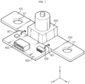
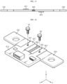
- FIG. 1 is an exploded perspective view schematically showing a configuration of a current measurement apparatus according to an embodiment of the present disclosure
- FIG. 2 is an assembled perspective view of FIG. 1 .
- the current measurement apparatus includes a first terminal 100, a second terminal 200, a resistor 300, a circuit board 400, a control unit 500, and a cutting unit 600.
- the first terminal 100 and the second terminal 200 may be made of an electrically conductive material.
- the first terminal 100 and the second terminal 200 may be made of a metal material such as copper.
- the first terminal 100 and the second terminal 200 are respectively connected to one side and the other side on a path through which current flows.
- the ends of the first terminal 100 and the second terminal 200 may be respectively connected to different charging and discharging bus bars, which constitute the same charging and discharging path of a battery pack.
- the first terminal 100 and the second terminal 200 may have a terminal hole, as indicated by H1 in the drawing, such that the terminal hole is coupled to the hole of the charging and discharging bus bar of the battery pack by bolting.
- the first terminal 100 and the second terminal 200 are disposed to be spaced apart from each other by a predetermined distance.
- the first terminal 100 and the second terminal 200 are configured to be spaced apart by a predetermined distance in a left and right direction (x-axis direction of the drawing).
- the resistor 300 is configured to be interposed in a separated space between the first terminal 100 and the second terminal 200.
- the resistor 300 may be configured to be fixedly coupled to the first terminal 100 and the second terminal 200.
- the resistor 300 may have one end (left end) coupled and fixed with the first terminal 100 and the other end (right end) coupled and fixed with the second terminal 200.
- the resistor 300 and the first terminal 100 and/or the second terminal 200 may be coupled by welding or the like, but various other coupling types may also be employed.
- the resistor 300 is made of an electrically conductive material having a greater resistance value, particularly a greater specific resistance, than the first terminal 100 and the second terminal 200.
- the resistor 300 may be made of an alloy material containing at least two or more of manganese (Mn), nickel (Ni), and copper (Cu).
- the material, configuration, shape, or the like of the first terminal 100, the second terminal 200 and the resistor 300 may employ those of a current sensor having a shunt resistor known at the time of filing of this application.
- the circuit board 400 is configured in a plate shape, like a printed circuit board (PCB), and may be configured to form an electric path on a surface thereof or at the inside thereof.
- the circuit board 400 is located at a side portion of the first terminal 100 and the second terminal 200.
- the circuit board 400 is be configured to be located at a side portion not in a direction where the first terminal 100 and the second terminal 200 are coupled but in a direction orthogonal thereto. For example, seeing the configuration of FIGS.
- the first terminal 100 and the second terminal 200 may be configured to be coupled in the left and right direction (x-axis direction of the drawing) with the resistor 300 interposed therebetween, and the circuit board 400 may be configured to be coupled in the front and rear direction (y-axis direction in the drawing).
- the circuit board 400 may be configured to be located at a front end of the first terminal 100, the second terminal 200, and the resistor 300.
- the circuit board 400 is configured to be electrically connected to the first terminal 100 and the second terminal 200, respectively.
- the circuit board 400 may include a plurality of measurement wires 401 made of a material through which an electric signal can be transmitted.
- the circuit board 400 may be electrically connected to the first terminal 100 through one of the measurement wires 401, and may be electrically connected to the second terminal 200 through another measurement wire 401.
- the measurement wire 401 may be connected and fixed to a conductor pattern or the like formed on the circuit board 400.
- the bonding and fixing between the measurement wire 401 and the terminals 100, 200 and/or between the measurement wire 401 and the circuit board 400 may be performed by soldering or the like, but various other bonding and fixing manners may also be implemented.
- the control unit 500 is mounted on the circuit board 400 and configured to measure the magnitude of current flowing through the resistor 300. More specifically, the control unit 500 may obtain a potential between the first terminal 100 and the second terminal 200 through the measurement wire 401. In addition, the control unit 500 may store the resistance value of the resistor 300 in advance in a memory or the like. Accordingly, the control unit 500 measures the magnitude of the current flowing through the resistor 300 by using the obtained voltage value between the first terminal 100 and the second terminal 200 and the resistance value of the resistor 300 stored in advance.
- the control unit 500 may be implemented in various forms such as a processor or a chipset known in the art, which may execute various control logics for measuring current and be mounted on the circuit board 400.
- the cutting unit 600 is located above or below the resistor 300.
- the cutting unit 600 may be configured to be placed on an upper surface of the resistor 300 as shown in FIGS. 1 and 2 .
- the cutting unit 600 may be configured to be also placed on an upper portion or a lower portion of the first terminal 100 and the second terminal 200 together with the resistor 300.
- a lower part of the cutting unit 600 may be placed in contact with the upper surface of the first terminal 100, another lower part thereof is may be placed in contact with the upper surface of the resistor 300, and still another lower part thereof may be placed in contact with the upper surface of the second terminal 200.
- the cutting unit 600 is configured to cut the resistor 300 according to a control signal of the control unit 500.
- the control unit 500 controls the cutting unit 600 to cut the resistor 300.
- the control unit 500 and the cutting unit 600 may be configured to send and receive electric signals to each other.
- the control unit 500 and the cutting unit 600 may be configured to be electrically connected to each other through a component such as a flexible printed circuit board (FPCB) or a wire.
- FPCB flexible printed circuit board
- the contact point between the FPCB or the like and the control unit 500 and/or the cutting unit 600 may be coated with a waterproof material.
- the control unit 500 and the cutting unit 600 may be configured to exchange signals with each other via an electric path of the circuit board 400, namely a conductor pattern.
- the control unit 500 may be configured to transmit a control signal for cutting to the cutting unit 600 when the current flowing through the resistor 300 is equal to or greater than a reference current.
- the reference current may be stored in advance in a memory device of the control unit 500 or the like.
- the cutting unit 600 may be configured to cut the resistor 300.
- the cutting unit 600 may be configured to cut the resistor 300 by applying a physical force to the resistor 300.
- the physical separation of the resistor 300 by the physical separation of the resistor 300, the flow of current through the first terminal 100, the resistor 300 and the second terminal 200 may be blocked. That is, if the resistor 300 is separated from the first terminal 100 and the second terminal 200, the electric connection state between the first terminal 100 and the second terminal 200 is cut off, and the flow of current passing through the first terminal 100, the resistor 300 and the second terminal 200 may not be formed any longer.
- the cutting unit 600 may be configured to press only the resistor 300 with respect to an assembly of the first terminal 100, the resistor 300 and the second terminal 200.
- the assembly of the first terminal 100, the resistor 300 and the second terminal 200 may be separated more easily. That is, the resistor 300 may be coupled and fixed with the first terminal 100 and the second terminal 200 by welding or the like, and the coupled and fixed portions between the resistor 300 and the first terminal 100 and between the resistor 300 and the second terminal 200 may be separated at one time by applying a physical force to the resistor 300. Therefore, in this case, the current may be blocked more quickly.
- the current blocking performance may be stably secured with a simple structure.
- the circuit board 400 is located at the side surface of the first terminal 100, the resistor 300 and the second terminal 200
- the cutting unit 600 is located above or below the first terminal 100, the resistor 300 and the second terminal 200.
- the cutting unit 600 may not disturb a connecting component such as a connection pin for measurement or the measurement wire 401 for the connection between the first terminal 100 and the circuit board 400 and between the second terminal 200 and the circuit board 400.
- the measurement wire 401 or the like does not need to be provided in a long shape. Therefore, the accuracy for current measurement and the structural coupling force between the circuit board 400 and the first terminal 100 and between the circuit board 400 and the second terminal 200 may be further improved.
- the current measurement apparatus of the present disclosure may have both the current measurement performance and the current blocking performance, without excessively increasing the volume. Therefore, when the current measurement apparatus is mounted to a battery pack or the like, the battery pack or the like may be designed easily, and the volume of the battery pack or the like may be prevented from increasing.
- the cutting unit 600 may be disposed above the resistor 300.
- the upper portion of the resistor 300 may be covered by the cutting unit 600, thereby more effectively preventing moisture or water existing inside the current measurement apparatus from being introduced toward the resistor 300.
- the cutting unit 600 prevents moisture or water droplets from being introduced toward the upper portion of the resistor 300, thereby preventing the accuracy of current measurement from deteriorating.
- the circuit board 400 may include a connector 402 for communication with an external device.
- a BMS provided in the battery pack may be connected to the current measurement apparatus through the connector 402.
- the BMS may receive the current measurement information of the current measurement apparatus through the connector 402.
- the circuit board 400 may further include various other components in addition to the connector 402 and the control unit 500.
- the first terminal 100 and the second terminal 200 are configured in a plate shape, as shown in FIGS. 1 and 2 .
- the first terminal 100 and the second terminal 200 may be configured in the form of a copper plate.
- the circuit board 400 is configured to be in a plate shape.
- the first terminal 100 and the second terminal 200 are configured to be located on the same plane as the circuit board 400. More specifically, the first terminal 100 and the second terminal 200 may be configured such that two wide surfaces are laid down to face upward and downward. In addition, the circuit board 400 may also be configured such that two wide surfaces are laid down to face upward and downward.
- the first terminal 100, the second terminal 200 and the circuit board 400 may be configured to be located on the same plane.
- the first terminal 100, the second terminal 200 and the circuit board 400 may all have a lower surface parallel to the x-y plane.
- a current measurement apparatus having a more compact size may be implemented.
- the first terminal 100, the second terminal 200 and the circuit board 400 may be stably mounted on the bottom surface of the current measurement apparatus.
- FIG. 3 is an exploded perspective view schematically showing a configuration of the current measurement apparatus according to an embodiment of the present disclosure.
- FIG. 3 features different from the former embodiment of FIGS. 1 and 2 will be described in detail.
- the current measurement apparatus may further include a case 700.
- the case 700 is an exterior material of the current measurement apparatus, and may be configured to have an inner space for accommodating at least a part of other components of the current measurement apparatus, such as the first terminal 100, the second terminal 200, the resistor 300, the circuit board 400, the control unit 500 and the cutting unit 600.
- the case 700 may be configured to include a lower case 701 and an upper case 702.
- an inner space is formed in the lower case 701 to accommodate other components of the current measurement apparatus, but an open portion may be formed at a top end thereof.
- the upper case 702 may be coupled to the top open portion of the lower case 701.
- the case 700 may protect various components provided therein from external physical and chemical factors.
- the case 700 for example the lower case 701, may be configured such that the first terminal 100 and the second terminal 200 are partially exposed to the outside for electric connection to the charging and discharging bus bar or the like.
- the case 700 may also be configured to expose the connector 402 to the outside, so that an external device such as a BMS may be easily connected to the connector 402 or the like.
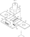
- FIG. 4 is an exploded perspective view schematically showing a configuration of a current measurement apparatus according to another embodiment of the present disclosure
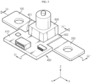
- FIG. 5 is an assembled perspective view of FIG. 4
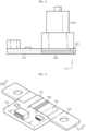
- FIG. 6 is a sectional view, taken along the line A1-A1' of FIG. 5 .
- features different from the former embodiments will be described in detail, and features identical or similar thereto will not be described in detail.
- the circuit board 400 includes a body portion 410 and an extending portion.
- the extending portion includes a first extending portion 421 and a second extending portion 422.
- the body portion 410 is a configuration located at the side portion of the first terminal 100 and the second terminal 200, and may be regarded as having a configuration corresponding to the circuit board 400 of FIGS. 1 and 2 as above. Accordingly, a conductor pattern may be formed on the body portion 410, and the control unit 500 may be mounted thereto.
- the first extending portion 421 is formed to extend in a horizontal direction from the body portion 410.
- the first extending portion 421 may be configured to extend in a y-axis direction, particularly in a -y-axis direction, on the x-y plane.
- the first extending portion 421 is
- the second extending portion 422 may be configured to extend in a horizontal direction from the body portion 410, particularly to extend in a direction parallel to the extending direction of the first extending portion 421.
- the second extending portion 422 may be configured to extend in the -y-axis direction, similar to the first extending portion 421.
- the second extending portion 422 is configured to be placed on a surface of the second terminal 200, for example an upper surface of the second terminal 200, as shown in FIGS. 4 to 6 .
- the coupling between the circuit board 400 and a resistor assembly which is an assembly of the first terminal 100, the resistor 300 and the second terminal 200, may be improved.
- a resistor assembly which is an assembly of the first terminal 100, the resistor 300 and the second terminal 200
- the first extending portion 421 and the second extending portion 422 are disposed on the upper portion or the lower portion of the first terminal 100 and the second terminal 200, it is possible to restrict upward or downward movement of the first terminal 100 and the second terminal 200. Accordingly, the mechanical coupling between the resistor assembly and the circuit board 400 may be improved.
- the circuit board 400 and each terminal may be electrically connected through the first extending portion 421 and the second extending portion 422.
- the conductor pattern formed on the body portion 410 may extend to the first extending portion 421 and the second extending portion 422.
- the conductor pattern formed on the first extending portion 421 and the second extending portion 422 may be connected to the first terminal 100 and the second terminal 200.
- the conductor patterns of the first extending portion 421 and the second extending portion 422 are formed to be buried inside a polymer layer, at least a part of the conductor pattern may be configured to be exposed to the outside of the polymer layer.
- the exposed part of the conductor pattern as described above may be in contact with the first terminal 100 and the second terminal 200 to be electrically connected to the first terminal 100 and the second terminal 200.
- the circuit board 400 and each terminal may be electrically connected more easily.
- an electric connection element such as the measurement wire 401 as shown in FIGS. 1 and 2 may not be included outside the circuit board 400.
- the thickness of the circuit board 400 may be configured to be greater than the thickness of the first terminal 100 and the second terminal 200.
- t1 and t2 may be configured to establish the following relationship. t1 > t2 .
- the vertical thickness of the second extending portion 422 extending from the body portion 410 of the circuit board 400 is t3
- the following relationship may be established for t1, t2 and t3.
- t1 may be equal to the sum of t2 and t3.
- the thickness of the laminate of the second extending portion 422 and the second terminal 200 is the same as the thickness of the body portion 410. Accordingly, the lower surface of the body portion 410 may be located on the same plane as the lower surface of the second terminal 200, and the upper surface of the body portion 410 may be located on the same plane as the upper surface of the second extending portion 422.
- this configuration may be identically applied to the first extending portion 421 and the first terminal 100. Accordingly, the bonding state among the circuit board 400, the terminal and the cutting unit 600 may be more stably maintained.
- the cutting unit 600 may be configured to be at least partially placed on the surfaces of both the first extending portion 421 and the second extending portion 422.
- a lower portion of one side of the cutting unit 600 may be placed on the first extending portion 421, and a lower portion of the other side of the cutting unit 600, for example a lower right side, may be placed on the second extending portion 422.
- the coupling between the cutting unit 600 and the circuit board 400 may be improved.
- the outer portions of the first extending portion 421 and the second extending portion 422 of the circuit board 400, namely the upper surfaces thereof, are configured to be flat, the cutting unit 600 may be stably placed on the flat surface.
- an empty space is formed between the first extending portion 421 and the second extending portion 422 above the resistor 300, it is possible to secure a space for locating the cutting configuration of the cutting unit 600 to cut the resistor 300.
- the first extending portion 421 and the second extending portion 422 serve to block fragments of the resistor 300, thereby preventing the fragments from scattering to the outside.
- the cutting unit 600 and the resistor assembly may not directly contact each other, it is possible to prevent the accuracy of current measurement from deteriorating due to current leakage or contact resistance.
- FIG. 7 is a perspective view schematically showing a configuration of a current measurement apparatus according to still another embodiment of the present disclosure
- FIG. 8 is an enlarged sectional view showing a portion A2 of FIG. 7 .
- features different from the former embodiments will be described in detail.
- the cutting unit 600 may be configured to protrude in an outer horizontal direction further to the first extending portion 421 and the second extending portion 422. That is, the cutting unit 600 may include a lower protrusion 601 protruding outward further to the first extending portion 421 and the second extending portion 421.
- a lower right end of the cutting unit 600 is placed on the second extending portion 422, and the right end of the cutting unit 600 may be configured to protrude in the right direction (+x-axis direction in the drawing) further to the second extending portion 422, thereby forming the lower protrusion 601.
- the lower protrusion 601 may be configured to be bent downward (-z-axis direction in the drawing) in the form of surrounding the outer side of the second extending portion 422 in a state of extending to the right further to the second extending portion 422. That is, the lower protrusion 601 of the cutting unit 600 may be configured to be bent in the form of surrounding the outer side of the second extending portion 422.
- FIG. 8 shows the configuration between the lower right end of the cutting unit 600 and the second extending portion 422
- the lower protrusion 601 may also be configured in a similar shape between the lower left end of the cutting unit 600 and the first extending portion 421. That is, at the lower left side of the cutting unit 600, the lower protrusion 601 configured to be bent in the form of surrounding the outer side, namely the left side, of the first extending portion 421 may be provided.
- the first extending portion 421 and the second extending portion 422 of the circuit board 400 are surrounded by the lower protrusion 601 of the cutting unit 600, it is possible to more effectively prevent foreign substances, particularly moisture or the like, from being introduced toward the resistor 300. That is, according to this configuration, the gap between the lower surface of the cutting unit 600 and the upper surface of the first extending portion 421 or the second extending portion 421 may not be exposed to the outside by the lower protrusion 601. Accordingly, it is possible to more reliably prevent foreign substances such as moisture from being introduced toward the resistor 300 located between the first extending portion 421 and the second extending portion 422 in the horizontal direction.
- the lower protrusion 601 may cover the side surfaces of the first extending portion 421 and the second extending portion 422 to protect the first extending portion 421 and the second extending portion 422 from external shocks or the like.
- FIG. 9 is a front sectional view schematically showing a configuration of a current measurement apparatus according to still another embodiment of the present disclosure.
- FIG. 9 may be regarded as another modification of the sectional configuration along the line A4-A4' of FIG. 5 .
- features different from the former embodiments will be described in detail.
- the current measurement apparatus may be configured such that outer upper parts of the first extending portion 421 and the second extending portion 422 are chamfered.
- the first extending portion 421 may be configured such that a left upper corner thereof is inclined, as indicated by A3 in FIG. 9 .
- the second extending portion 422 may be configured such that a right upper corner is inclined, as indicated by A3' in FIG. 9 .
- the chamfered portion may be configured in a curved shape.
- the chamfered portion may be formed in a region located outside the cutting unit 600 in the horizontal direction.
- this configuration of the present disclosure it is possible to more reliably prevent moisture or the like from penetrating toward the resistor 300.
- the water droplet falling onto the first extending portion 421 or the second extending portion 422 may flow more easily in a direction opposite to the resistor 300 through the chamfered portion. Therefore, it is possible to more reliably prevent the accuracy of current measurement from deteriorating due to the penetration of moisture toward the resistor 300.
- FIG. 10 is a perspective view schematically showing a configuration of a current measurement apparatus according to still another embodiment of the present disclosure
- FIG. 11 is a sectional view, taken along the line A5-A5' of FIG. 10 .
- the cutting unit 600 is not illustrated for convenience of explanation. In this embodiment, features different from the former embodiments will be described in detail.
- the circuit board 400 of the current measurement apparatus may include a third extending portion 423.
- the third extending portion 423 may be configured to connect an end of the first extending portion 421 and an end of the second extending portion 422 to each other.
- a left end of the third extending portion 423 may be connected to a rear end of the first extending portion 421, and a right end of the third extending portion 423 may be connected to a rear end of the second extending portion 422.
- the cutting unit 600 may be placed on the third extending portion 423. That is, as shown in FIG. 11 , the rear end of the cutting unit 600 may be placed on the third extending portion 423.
- the cutting unit 600 may be regarded as being placed on all of the first extending portion 421, the second extending portion 422 and the third extending portion 423. Moreover, the cutting unit 600 may be partially placed on the body portion 410 as shown in FIG. 11 .
- the circuit board 400 is located in the horizontal direction, namely all of the front, rear, left and right directions, around the resistor 300.
- the cutting unit 600 is located on the resistor 300. Therefore, it is possible to more completely block the penetration of foreign substances such as moisture toward the resistor 300.
- the cutting unit 600 may also be configured to be partially placed on the body portion 410. In this case, the upper portion of the resistor 300 may be more reliably sealed by the cutting unit 600.
- the third extending portion 423 may be configured to be bent in the form of surrounding the outer side portion (rear side portion) of the resistor 300. That is, the third extending portion 423 may be configured to be bent downward in a shape of surrounding the rear side portion of the resistor 300.
- the circuit board 400 may be configured to have a thickness capable of blocking the other outer side portion (front side portion) of the resistor 300. In this case, the resistor 300 is more securely sealed from the outside by the body portion 410 and the third extending portion 423, thereby further improving the water penetration blocking effect to the resistor 300.
- FIG. 12 is a perspective view schematically showing a configuration of a current measurement apparatus according to still another embodiment of the present disclosure
- FIG. 13 is a sectional view, taken along the line A6-A6' of FIG. 12 .
- components such as the cutting unit 600 are not illustrated for convenience of explanation. In this embodiment, features different from the former embodiments will be described in detail.
- the first extending portion 421 and the second extending portion 422 may be configured to be located at different portions in the vertical direction based on the resistor 300.
- the first extending portion 421 may be placed in contact with the upper surface of the first terminal 100
- the second extending portion 422 may be placed in contact with the lower surface of the second terminal 200.
- the coupling force between the circuit board 400 and the resistor assembly including the first terminal 100, the resistor 300 and the second terminal 200 may be further increased.
- upward movement of the resistor assembly may be restricted by the first extending portion 421, and downward movement may be restricted by the second extending portion 422. That is, both upward and downward movement of the resistor assembly may be restricted by the circuit board 400.
- the first extending portion 421 or the second extending portion 422 may support the resistor assembly in a direction opposite to the pressing direction. Therefore, the resistor 300 may be cut by the cutting unit 600 more smoothly and quickly.
- the coupling force between the circuit board 400 and the resistor assembly may be improved, thereby further enhancing the mechanical stability of the current measurement apparatus.
- the circuit board 400 may be configured to be detachably attached to the resistor assembly, particularly the first terminal 100 and the second terminal 200. This will be described in more detail with reference to FIG. 14 .
- FIG. 14 is an exploded perspective view schematically showing a partial configuration of a current measurement apparatus according to still another embodiment of the present disclosure. In this embodiment, features different from the former embodiments will be described in detail.
- the circuit board 400 may be coupled to the first terminal 100 and the second terminal 200 by a fastening member such as a bolt. More specifically, in the first extending portion 421 of the circuit board 400, a first coupling hole may be formed to be perforated in the vertical direction, as indicated by H21. In addition, a first perforation hole may also be formed in the first terminal 100 at a position and in a shape corresponding to the first coupling hole H21. In addition, in the second extending portion 422 of the circuit board 400, a second coupling hole may be formed to be perforated in the vertical direction, as indicated by H22. In addition, a second perforation hole may also be formed in the second terminal 200 at a position and in a shape corresponding to the second coupling hole H22.
- first bolt B1 may be inserted into the first coupling hole H21 and the first perforation hole to fasten the first extending portion 421 and the first terminal 100 with each other.
- second bolt B2 may be inserted into the second coupling hole H22 and the second perforation hole to fasten the second extending portion 422 and the second terminal 200 with each other. Also, if the first bolt B 1 and the second bolt B2 are separated from each hole, the circuit board 400 and each terminal may be separated from each other.
- the resistor assembly and the circuit board 400 may be easily attached and detached.
- the resistor 300 may be cut by the cutting unit 600.
- the resistor assembly needs to be replaced with a new one.
- the resistor assembly just by loosening the bolts B1, B2, the resistor assembly may be easily separated from the circuit board 400 and replaced with another new resistor assembly. Accordingly, the circuit board 400 and the like may be used continuously.
- the bolts B1, B2 may fasten not only the resistor assembly 100, 200, 300 and the circuit board 400 to each other, but also the cutting unit 600.
- a fastening hole may also be formed in the cutting unit 600 at a position and in a shape corresponding to the first coupling hole H21 and the second coupling hole H22, and the bolts B1, B2 may also be inserted into these fastening hole.
- the resistor assembly 100, 200, 300, the circuit board 400, and the cutting unit 600 may be coupled and fixed at once.
- the circuit board 400 and the terminals 100, 200 may be electrically connected by the bolts B1, B2. That is, the first bolt B1 may be made of a conductor material and be configured to electrically connect the conductor pattern of the first extending portion 421 to the first terminal 100. In addition, the second bolt B2 may also be made of a conductor material and be configured to electrically connect the conductor pattern of the second extending portion 422 to the second terminal 200. According to this configuration of the present disclosure, the extending portions 421, 422 of the circuit board 400 and the terminals 100, 200 of the resistor assembly may be connected electrically and mechanically at once by fastening the bolts.
- the circuit board 400 and the terminal may be electrically connected by a ring terminal wire or the like.
- one end of the ring terminal wire may be fastened to the first coupling hole H21 and the first fastening hole by the first bolt B1 to be mechanically and electrically connected to the first terminal 100
- the other end of the ring terminal wire may be mechanically and electrically connected to the body portion 410 of the circuit board 400 by another bolt or the like.
- one end and the other end of another ring terminal wire may be mechanically and electrically connected to the second coupling hole H22 and the second fastening hole and the body portion 410 of the circuit board 400, respectively.
- the cutting unit 600 may be configured to contain a gunpowder therein.
- the cutting unit 600 may be configured to explode the contained gunpowder and cut the resistor 300 by the explosion of the gunpowder.
- the cutting unit 600 may explode the gunpowder based on a control signal of the control unit 500.
- the cutting unit 600 may be electrically connected to the control unit 500 to receive a control signal from the control unit 500.
- the cutting unit 600 may be connected to the control unit 500 through an FPCB.
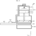
- FIG. 15 is a side sectional view schematically showing a configuration of a current measurement apparatus according to still another embodiment of the present disclosure. In this embodiment, features different from the former embodiments will be described in detail.
- the cutting unit 600 is mainly illustrated, and other components are illustrated in a simplified form.
- the cutting unit 600 may include an explosion portion 610, a pressing portion 620, and a cover portion 630.
- the explosion portion 610 may be located above or below the resistor 300, and may be configured to apply a cutting force due to the explosion to the resistor 300. More specifically, in FIG. 15 , the explosion portion 610 is located above the resistor 300, and may include a gunpowder 611, an ignition switch 612, a cylinder 613, and a piston 614.
- the ignition switch 612 may be connected to the control unit 500 through an electric connection element, as indicated by F in the drawing.
- the electric connection element may be an FPCB, but other various types of connection elements may be used. Then, the ignition switch 612 may ignite a flame when a cutting signal is received from the control unit 500, so that the gunpowder 612 contained in the cylinder 613 explodes.
- the pressure inside the cylinder 613 increases, and the piston 614 may move downward quickly and strongly.
- the pressing portion 620 may be connected to the piston 614.
- the pressing portion 620 may be configured to directly press the resistor 300 by receiving a force by the explosion force of the explosion portion 610. More specifically, if the piston 614 moves downward quickly and strongly, eventually, as indicated by an arrow in the drawing, the pressing portion 620 connected to the piston 614 also moves downward quickly and strongly.
- the movement of the pressing portion 620 may apply a pressure to the resistor 300 to cut the resistor 300 itself or disconnect the coupling between the resistor 300 and the first terminal 100 and/or between the resistor 300 and the second terminal 200. Therefore, a current may not flow through resistor assembly 100, 200, 300 any longer.
- the cutting unit 600 may include a cover portion 630.
- the cover portion 630 may be located opposite to the pressing portion 620 based on the resistor 300.
- the pressing portion 620 may be located above the resistor 300, and the cover portion 630 may be located below the resistor 300.
- the cover portion 630 may be configured to prevent fragments of the resistor 300 cut by the pressing force of the pressing portion 620 from scattering.
- the cover portion 630 may have an empty space therein, and may be configured such that its side where the resistor 300 is located is open and all other sides are closed. For example, as in the configuration shown in FIG.
- the cover portion 630 when the resistor 300 is located at an upper side, the cover portion 630 may be configured such that its upper portion is open and both lower and side portions are closed. According to this configuration of the present disclosure, when the resistor 300 is separated or damaged by the explosion portion 610 and the pressing portion 620, it is possible to prevent the separated or damaged resistor 300 or its fragments from scattering to the outside of the cutting unit 600. Accordingly, it is possible to prevent the configuration of the cutting unit 600 for cutting the resistor 300 from damaging other components of the current measurement apparatus.
- FIG. 16 is a side sectional view schematically showing a configuration of a current measurement apparatus according to still another embodiment of the present disclosure. In this embodiment, features different from the former embodiments will be described in detail.
- the circuit board 400 may include a heat dissipation member 430.
- the heat dissipation member 430 may be mostly attached to the surface of the circuit board 400, for example the upper surface of the body portion 410.
- the heat dissipation member 430 may include a heat dissipation portion 431 for dissipating heat and a heat absorption portion 432 for absorbing heat.
- the heat dissipation member 430 may be configured to absorb heat generated from the resistor assembly, particularly the first terminal 100 and the second terminal 200.
- the heat absorption portion 432 of the heat dissipation member 430 may be configured to directly or indirectly contact at least one of the first terminal 100, the resistor 300 and the second terminal 200 while maintaining electric insulation therewith.
- the heat absorbed from the resistor assembly through the heat absorption portion 432 in this way may be discharged to the outside through the heat dissipation portion 431, as indicated by arrows.
- the heat dissipation member 430 may be implemented in various types of heat dissipation configurations, such as a heatsink, known at the time of filing of this application.
- a heat transfer material T may be interposed between the heat dissipation member 430 and at least one of the first terminal 100, the resistor 300 and the second terminal 200.
- a gel-like heat transfer material T may be interposed between the first terminal 100 and the heat absorption portion 432 of the heat dissipation member 430.
- a heat transfer material T may also be interposed between the resistor 300 and/or the second terminal 200 and the heat absorption portion 432 of the heat dissipation member 430.
- the heat transfer material T may be made of a material having high thermal conductivity and electric insulation. The heat transfer material T is widely known at the time of filing of this application and will not be described in detail here.
- the heat of the resistor assembly may be more smoothly discharged to the outside.
- the resistor 300 due to the temperature coefficient of resistance (TCR) characteristics, it is necessary to compensate in consideration of the effect of temperature when measuring current.
- TCR temperature coefficient of resistance
- the heat absorption portion 432 may be configured to protrude downward below the heat dissipation portion 431 and to be coupled in contact with the inside of the body portion 410 of the circuit board 400. More specifically, one surface (the left surface in the drawing) of the heat absorption portion 432 may be in contact with the body portion 410, and the other surface (the right surface in the drawing) of the heat absorption portion 432 may be in contact with at least one of the first terminal 100, the resistor 300 and the second terminal 200. That is, the heat absorption portion 432 may be fixed in a state of being interposed between the body portion 410 and the resistor assembly 100, 200, 300, when viewed in the y-axis direction of FIG. 16 . In addition, the heat absorption portion 432 may be interposed between the first extending portion 421 and the second extending portion 422, when viewed in the x-axis direction of FIG. 14 .
- the heat dissipation member 430 may be more stably fixed on the surface of the body portion 410. That is, in the heat dissipation member 430, movement of the heat absorption portion 432 in the left and right direction (x-axis direction in the drawing) may be restricted by the first extending portion 421 and the second extending portion 422, and movement of the heat absorption portion 432 in the front and rear direction (y-axis direction in the drawing) may be restricted by the body portion 410 and the resistor assembly.
- the current measurement apparatus may be applied to a battery pack.
- the battery pack according to the present disclosure may include the current measurement apparatus described above.
- the battery pack according to the present disclosure further includes general components included in a battery pack, such as a battery cell, a pack case, a BMS, a charging and discharging bus bar, a voltage sensing assembly and the like, in addition to the current measurement apparatus.
- the current measurement apparatus according to the present disclosure may be applied to a vehicle. Accordingly, the vehicle according to the present disclosure may include the current measurement apparatus described above. In addition, the vehicle according to the present disclosure may further include general components included in a vehicle, such as a vehicle body, a motor, a drive shaft and the like, in addition to the current measurement apparatus.
Landscapes
- Engineering & Computer Science (AREA)
- General Physics & Mathematics (AREA)
- Physics & Mathematics (AREA)
- Chemical & Material Sciences (AREA)
- General Chemical & Material Sciences (AREA)
- Electrochemistry (AREA)
- Chemical Kinetics & Catalysis (AREA)
- Manufacturing & Machinery (AREA)
- Power Engineering (AREA)
- Sustainable Development (AREA)
- Mechanical Engineering (AREA)
- Transportation (AREA)
- Sustainable Energy (AREA)
- Life Sciences & Earth Sciences (AREA)
- Microelectronics & Electronic Packaging (AREA)
- Measuring Instrument Details And Bridges, And Automatic Balancing Devices (AREA)
- Testing Electric Properties And Detecting Electric Faults (AREA)
Claims (9)
- Strommessvorrichtung, umfassend:einen ersten Anschluss (100), welcher aus einem elektrisch leitenden Material gefertigt ist;einen zweiten Anschluss (200), welcher aus einem elektrisch leitenden Material gefertigt und derart angeordnet ist, dass er von dem ersten Anschluss (100) um eine vorbestimmte Distanz beabstandet ist;einen Widerstand (300), welcher in einem getrennten Raum zwischen dem ersten Anschluss (100) und dem zweiten Anschluss (200) eingefügt ist;eine Platine (400), welche einen elektrischen Pfad aufweist, welcher an einem Seitenabschnitt des ersten Anschlusses (100) und des zweiten Anschlusses (200) angeordnet und jeweils elektrisch mit dem ersten Anschluss (100) und dem zweiten Anschluss (200) verbunden ist;eine Steuerungseinheit (500), welche an der Platine (400) montiert und dazu eingerichtet ist, den Strom, welcher in dem Widerstand (300) fließt, durch Verwendung eines Spannungswertes zwischen dem ersten Anschluss (100) und dem zweiten Anschluss (200) und eines Widerstandswertes des Widerstands (300) zu messen; und wobei die Strommessvorrichtung dadurch gekennzeichnet ist, dass der Widerstand aus einem elektrisch leitenden Material gefertigt ist, welches einen größeren spezifischen Widerstand aufweist als der erste Anschluss (100) und der zweite Anschluss (200); und dadurch, dass die Strommessvorrichtung ferner umfasst:eine Trenneinheit (600), welche über oder unter dem Widerstand (300) angeordnet und dazu eingerichtet ist, den Widerstand (300) gemäß eines Steuersignals der Steuerungseinheit (500) zu trennen,wobei der erste Anschluss (100) und der zweite Anschluss (200) in einer Plattenform eingerichtet und auf der gleichen Ebene angeordnet sind wie die Platine (400),wobei die Platine (400) einen Körperabschnitt (410), welcher an dem Seitenabschnitt des ersten Anschlusses (100) und des zweiten Anschlusses (200) angeordnet ist, einen ersten Erstreckungsabschnitt (421), welcher gebildet ist, um sich in einer horizontalen Richtung von dem Körperabschnitt (410) zu erstrecken, und dazu eingerichtet ist, an einer Fläche des ersten Anschlusses (100) platziert zu sein, und einen zweiten Erstreckungsabschnitt (422) umfasst, welcher dazu eingerichtet ist, an einer Fläche des zweiten Anschlusses (200) platziert zu sein.
- Strommessvorrichtung nach Anspruch 1,
wobei die Trenneinheit (600) dazu eingerichtet ist, wenigstens teilweise an den Flächen sowohl des ersten Erstreckungsabschnitts (421) als auch des zweiten Erstreckungsabschnitts (422) platziert zu sein. - Strommessvorrichtung nach Anspruch 2,
wobei die Trenneinheit (600) dazu eingerichtet ist, in einer horizontalen Richtung weiter zu dem ersten Erstreckungsabschnitt (421) und dem zweiten Erstreckungsabschnitt (422) nach außen hervorzustehen. - Strommessvorrichtung nach Anspruch 1,
wobei die Platine (400) dazu eingerichtet ist, entfernbar an dem ersten Anschluss (100) und dem zweiten Anschluss (200) angebracht zu sein. - Strommessvorrichtung nach Anspruch 1,
wobei die Trenneinheit (600) darin Schießpulver (611) beinhaltet und dazu eingerichtet ist, den Widerstand (300) durch Explodieren des Schießpulvers (611) zu trennen. - Strommessvorrichtung nach Anspruch 5,
wobei die Trenneinheit (600) einen Explosionsabschnitt (610), welcher über oder unter dem Widerstand (300) angeordnet und dazu eingerichtet ist, eine Trennkraft durch Explosion auf den Widerstand (300) auszuüben, einen Pressabschnitt (620), welcher dazu eingerichtet ist, den Widerstand (300) durch eine Explosionskraft des Explosionsabschnitts (610) zu pressen, und einen Abdeckungsabschnitt (630) umfasst, welcher basierend auf dem Widerstand (300) entgegengesetzt zu dem Pressabschnitt (620) angeordnet und dazu eingerichtet ist, zu verhindern, dass der Widerstand (300), welcher durch die Presskraft des Pressabschnitts (620) getrennt ist, zerstreut wird. - Strommessvorrichtung nach Anspruch 1,
wobei die Platine (400) ein Wärmedissipationselement (430), welches an einer Fläche davon bereitgestellt ist, und ein Wärmetransfermaterial umfasst, welches zwischen dem Wärmedissipationselement (430) und wenigstens einem von dem ersten Anschluss (100), dem Widerstand (300) und dem zweiten Anschluss (200) eingefügt ist. - Batteriepack, umfassend die Strommessvorrichtung nach einem der Ansprüche 1 bis 7.
- Fahrzeug, umfassend die Strommessvorrichtung nach einem der Ansprüche 1 bis 7.
Applications Claiming Priority (2)
| Application Number | Priority Date | Filing Date | Title |
|---|---|---|---|
| KR1020200089756A KR102747401B1 (ko) | 2020-07-20 | 2020-07-20 | 전류 측정 장치 |
| PCT/KR2021/009064 WO2022019565A1 (ko) | 2020-07-20 | 2021-07-14 | 전류 측정 장치 |
Publications (3)
| Publication Number | Publication Date |
|---|---|
| EP4148433A1 EP4148433A1 (de) | 2023-03-15 |
| EP4148433A4 EP4148433A4 (de) | 2023-11-08 |
| EP4148433B1 true EP4148433B1 (de) | 2024-12-18 |
Family
ID=79728824
Family Applications (1)
| Application Number | Title | Priority Date | Filing Date |
|---|---|---|---|
| EP21847084.7A Active EP4148433B1 (de) | 2020-07-20 | 2021-07-14 | Strommessvorrichtung |
Country Status (8)
| Country | Link |
|---|---|
| US (1) | US12113346B2 (de) |
| EP (1) | EP4148433B1 (de) |
| JP (1) | JP2023509874A (de) |
| KR (1) | KR102747401B1 (de) |
| CN (1) | CN114981669B (de) |
| ES (1) | ES3010506T3 (de) |
| HU (1) | HUE069707T2 (de) |
| WO (1) | WO2022019565A1 (de) |
Families Citing this family (1)
| Publication number | Priority date | Publication date | Assignee | Title |
|---|---|---|---|---|
| JP7633976B2 (ja) * | 2022-09-27 | 2025-02-20 | 矢崎総業株式会社 | 電流検出装置 |
Citations (1)
| Publication number | Priority date | Publication date | Assignee | Title |
|---|---|---|---|---|
| JPH06294821A (ja) * | 1993-02-15 | 1994-10-21 | Soc Appl Gen Electr Mec <Sagem> | 電流測定用分流器素子及びそれを用いる接続測定モジュール |
Family Cites Families (27)
| Publication number | Priority date | Publication date | Assignee | Title |
|---|---|---|---|---|
| JP4069219B2 (ja) | 1997-10-17 | 2008-04-02 | 太平洋精工株式会社 | センサー付きヒューズ |
| US20040041682A1 (en) * | 2002-08-29 | 2004-03-04 | Pasha Brian D. | Battery circuit disconnect device |
| US7123124B2 (en) | 2003-10-17 | 2006-10-17 | Special Devices, Inc. | Pyrotechnic circuit breaker |
| JP2005127832A (ja) * | 2003-10-23 | 2005-05-19 | Auto Network Gijutsu Kenkyusho:Kk | 電圧降下式電流計測装置 |
| JP4272044B2 (ja) | 2003-12-08 | 2009-06-03 | 太平洋精工株式会社 | 電流センサ内蔵ヒューズ装置 |
| JP2008039571A (ja) | 2006-08-04 | 2008-02-21 | Denso Corp | 電流センサ |
| JP2009052898A (ja) * | 2007-08-23 | 2009-03-12 | Mitsubishi Electric Corp | 電流検出基板 |
| KR20110002707A (ko) | 2009-07-02 | 2011-01-10 | 주식회사 하이닉스반도체 | 반도체 장치의 퓨즈 및 그 제조방법 |
| JP2012059815A (ja) | 2010-09-07 | 2012-03-22 | Elpida Memory Inc | 半導体装置 |
| JP6034710B2 (ja) | 2013-01-31 | 2016-11-30 | 矢崎総業株式会社 | 電線ヒューズ及び電線ヒューズの製造方法 |
| KR101614202B1 (ko) | 2013-08-28 | 2016-04-21 | 주식회사 엘지화학 | 전류 측정 릴레이 장치 |
| JP5928430B2 (ja) | 2013-10-03 | 2016-06-01 | トヨタ自動車株式会社 | 電流センサ、電力変換装置 |
| KR101461829B1 (ko) | 2013-11-26 | 2014-11-13 | 스마트전자 주식회사 | 전류측정소자 및 전류측정소자 어셈블리의 제조방법 |
| KR20160112417A (ko) * | 2015-03-19 | 2016-09-28 | 주식회사 엘지화학 | 과충전 방지용 안전구조를 포함하는 전지팩 |
| KR101720931B1 (ko) | 2015-07-01 | 2017-04-10 | (주)청앤생 | 전기 자동차용 회로 차단 장치 |
| US10598703B2 (en) | 2015-07-20 | 2020-03-24 | Eaton Intelligent Power Limited | Electric fuse current sensing systems and monitoring methods |
| CN205984481U (zh) | 2016-08-26 | 2017-02-22 | 中国振华集团云科电子有限公司 | 芯片电阻器 |
| DE102016216829A1 (de) | 2016-09-06 | 2018-03-08 | Bayerische Motoren Werke Aktiengesellschaft | Trenneinrichtung zum Trennen einer elektrischen Verbindung zwischen zwei Komponenten eines Kraftfahrzeugs, sowie Vorrichtung mit einer solchen Trenneinrichtung |
| JP2018189384A (ja) * | 2017-04-28 | 2018-11-29 | 株式会社Gsユアサ | 電流検出装置、管理装置、エンジン始動用のバッテリ |
| DE102017118416A1 (de) | 2017-08-11 | 2019-02-14 | Ruag Ammotec Gmbh | Pyrotechnische Trenneinrichtung, System zum elektrischen Laden einer elektrischen Energiezelle, Mobilgerät und Ladegerät |
| KR102264409B1 (ko) * | 2018-03-16 | 2021-06-21 | 주식회사 엘지에너지솔루션 | 통합형 스위칭 장치 |
| AU2019202101A1 (en) | 2018-05-10 | 2019-11-28 | Eavor Technologies Inc | Fluid for use in power production environments |
| KR102258813B1 (ko) * | 2018-11-20 | 2021-05-31 | 주식회사 엘지에너지솔루션 | 복합형 전류 측정장치 |
| KR102312332B1 (ko) | 2018-12-18 | 2021-10-12 | 주식회사 엘지에너지솔루션 | 나사 체결 구조를 갖는 션트 저항 모듈 |
| JP2020106330A (ja) | 2018-12-26 | 2020-07-09 | デクセリアルズ株式会社 | 電流検知素子、電流検知素子複合体および保護回路 |
| CN210404710U (zh) * | 2019-08-28 | 2020-04-24 | 比亚迪股份有限公司 | 用于熔断装置的控制电路及车辆 |
| CN110797835A (zh) | 2019-10-16 | 2020-02-14 | 上海西埃新能源科技有限公司 | 烟火式安全开关 |
-
2020
- 2020-07-20 KR KR1020200089756A patent/KR102747401B1/ko active Active
-
2021
- 2021-07-14 JP JP2022538918A patent/JP2023509874A/ja active Pending
- 2021-07-14 EP EP21847084.7A patent/EP4148433B1/de active Active
- 2021-07-14 HU HUE21847084A patent/HUE069707T2/hu unknown
- 2021-07-14 CN CN202180010046.XA patent/CN114981669B/zh active Active
- 2021-07-14 US US17/798,183 patent/US12113346B2/en active Active
- 2021-07-14 ES ES21847084T patent/ES3010506T3/es active Active
- 2021-07-14 WO PCT/KR2021/009064 patent/WO2022019565A1/ko not_active Ceased
Patent Citations (1)
| Publication number | Priority date | Publication date | Assignee | Title |
|---|---|---|---|---|
| JPH06294821A (ja) * | 1993-02-15 | 1994-10-21 | Soc Appl Gen Electr Mec <Sagem> | 電流測定用分流器素子及びそれを用いる接続測定モジュール |
Also Published As
| Publication number | Publication date |
|---|---|
| WO2022019565A1 (ko) | 2022-01-27 |
| JP2023509874A (ja) | 2023-03-10 |
| ES3010506T3 (en) | 2025-04-03 |
| CN114981669A (zh) | 2022-08-30 |
| EP4148433A1 (de) | 2023-03-15 |
| CN114981669B (zh) | 2025-08-12 |
| KR102747401B1 (ko) | 2024-12-26 |
| KR20220010962A (ko) | 2022-01-27 |
| EP4148433A4 (de) | 2023-11-08 |
| US12113346B2 (en) | 2024-10-08 |
| HUE069707T2 (hu) | 2025-04-28 |
| US20230070670A1 (en) | 2023-03-09 |
Similar Documents
| Publication | Publication Date | Title |
|---|---|---|
| EP1807900B1 (de) | Bauteil zum messen der zellspannung und temperatur in einem batteriepack | |
| KR101386167B1 (ko) | 배터리 팩 | |
| KR101925934B1 (ko) | 배터리 팩 | |
| EP3836247A1 (de) | Batteriemodul, batteriesatz mit solch einem batteriemodul und fahrzeug mit solch einem batteriesatz | |
| KR102152364B1 (ko) | 배터리 팩 | |
| US9269946B2 (en) | Battery pack having protection circuit module | |
| US11056748B2 (en) | Protection device used in battery pack, battery pack and vehicle | |
| CN108155429B (zh) | 过充安全保护装置 | |
| KR102441019B1 (ko) | 외부 단락 방지 구조가 적용된 배터리 모듈 | |
| EP4053989A1 (de) | Batteriemodul mit stromschiene, batteriepack und fahrzeug | |
| JP2020514983A (ja) | バッテリーモジュール、それを含むバッテリーパック及び自動車 | |
| KR20150034495A (ko) | 전압 센싱 어셈블리 및 이를 포함하는 전지모듈 | |
| KR102352625B1 (ko) | 외부 단락 방지 구조가 적용된 배터리 모듈을 이용한 배터리 팩 | |
| US11477885B2 (en) | Redundant trace fuse for a conformal wearable battery | |
| KR20170040638A (ko) | 배터리 모듈 및 이를 포함하는 배터리 팩 | |
| KR20140096197A (ko) | 배터리 팩 | |
| US20240224424A1 (en) | Conformal Wearable Battery | |
| EP4148433B1 (de) | Strommessvorrichtung | |
| KR20170040636A (ko) | 배터리 모듈 및 이를 포함하는 배터리 팩 | |
| KR20230096912A (ko) | 배터리 모듈 및 이를 포함하는 배터리 팩 및 자동차 | |
| CN115917834B (zh) | 电池模块、包括该电池模块的电池组和电动车辆 | |
| KR20220052823A (ko) | 배터리 팩, 전자 디바이스, 및 자동차 | |
| EP4235949A1 (de) | Batteriepack mit verbesserter sicherheit | |
| EP4462585B1 (de) | Sammelschienenanordnung mit verbesserter temperaturmessung für sammelschiene und batteriepack damit | |
| US20250149664A1 (en) | Battery cell assembly including thermistor and method of manufacturing the same |
Legal Events
| Date | Code | Title | Description |
|---|---|---|---|
| STAA | Information on the status of an ep patent application or granted ep patent |
Free format text: STATUS: THE INTERNATIONAL PUBLICATION HAS BEEN MADE |
|
| PUAI | Public reference made under article 153(3) epc to a published international application that has entered the european phase |
Free format text: ORIGINAL CODE: 0009012 |
|
| STAA | Information on the status of an ep patent application or granted ep patent |
Free format text: STATUS: REQUEST FOR EXAMINATION WAS MADE |
|
| 17P | Request for examination filed |
Effective date: 20221205 |
|
| AK | Designated contracting states |
Kind code of ref document: A1 Designated state(s): AL AT BE BG CH CY CZ DE DK EE ES FI FR GB GR HR HU IE IS IT LI LT LU LV MC MK MT NL NO PL PT RO RS SE SI SK SM TR |
|
| REG | Reference to a national code |
Ref country code: DE Ref legal event code: R079 Free format text: PREVIOUS MAIN CLASS: G01R0019000000 Ipc: G01R0001200000 Ref document number: 602021023702 Country of ref document: DE |
|
| DAV | Request for validation of the european patent (deleted) | ||
| DAX | Request for extension of the european patent (deleted) | ||
| A4 | Supplementary search report drawn up and despatched |
Effective date: 20231011 |
|
| RIC1 | Information provided on ipc code assigned before grant |
Ipc: H01H 39/00 20060101ALI20231005BHEP Ipc: G01R 31/385 20190101ALI20231005BHEP Ipc: G01R 31/3842 20190101ALI20231005BHEP Ipc: G01R 1/36 20060101ALI20231005BHEP Ipc: G01R 1/20 20060101AFI20231005BHEP |
|
| STAA | Information on the status of an ep patent application or granted ep patent |
Free format text: STATUS: EXAMINATION IS IN PROGRESS |
|
| 17Q | First examination report despatched |
Effective date: 20240305 |
|
| GRAP | Despatch of communication of intention to grant a patent |
Free format text: ORIGINAL CODE: EPIDOSNIGR1 |
|
| STAA | Information on the status of an ep patent application or granted ep patent |
Free format text: STATUS: GRANT OF PATENT IS INTENDED |
|
| RIC1 | Information provided on ipc code assigned before grant |
Ipc: H01M 50/583 20210101ALI20240610BHEP Ipc: H01M 10/48 20060101ALI20240610BHEP Ipc: H01M 10/42 20060101ALI20240610BHEP Ipc: B60L 3/00 20190101ALI20240610BHEP Ipc: G01R 1/36 20060101ALI20240610BHEP Ipc: G01R 19/165 20060101ALI20240610BHEP Ipc: H01H 39/00 20060101ALI20240610BHEP Ipc: H01H 71/12 20060101ALI20240610BHEP Ipc: H01H 9/52 20060101ALI20240610BHEP Ipc: G01R 1/20 20060101AFI20240610BHEP |
|
| INTG | Intention to grant announced |
Effective date: 20240703 |
|
| P01 | Opt-out of the competence of the unified patent court (upc) registered |
Free format text: CASE NUMBER: APP_44517/2024 Effective date: 20240731 |
|
| GRAJ | Information related to disapproval of communication of intention to grant by the applicant or resumption of examination proceedings by the epo deleted |
Free format text: ORIGINAL CODE: EPIDOSDIGR1 |
|
| STAA | Information on the status of an ep patent application or granted ep patent |
Free format text: STATUS: EXAMINATION IS IN PROGRESS |
|
| GRAS | Grant fee paid |
Free format text: ORIGINAL CODE: EPIDOSNIGR3 |
|
| STAA | Information on the status of an ep patent application or granted ep patent |
Free format text: STATUS: GRANT OF PATENT IS INTENDED |
|
| GRAP | Despatch of communication of intention to grant a patent |
Free format text: ORIGINAL CODE: EPIDOSNIGR1 |
|
| INTC | Intention to grant announced (deleted) | ||
| GRAA | (expected) grant |
Free format text: ORIGINAL CODE: 0009210 |
|
| STAA | Information on the status of an ep patent application or granted ep patent |
Free format text: STATUS: THE PATENT HAS BEEN GRANTED |
|
| INTG | Intention to grant announced |
Effective date: 20241021 |
|
| AK | Designated contracting states |
Kind code of ref document: B1 Designated state(s): AL AT BE BG CH CY CZ DE DK EE ES FI FR GB GR HR HU IE IS IT LI LT LU LV MC MK MT NL NO PL PT RO RS SE SI SK SM TR |
|
| REG | Reference to a national code |
Ref country code: CH Ref legal event code: EP |
|
| REG | Reference to a national code |
Ref country code: DE Ref legal event code: R096 Ref document number: 602021023702 Country of ref document: DE |
|
| REG | Reference to a national code |
Ref country code: IE Ref legal event code: FG4D |
|
| REG | Reference to a national code |
Ref country code: LT Ref legal event code: MG9D |
|
| PG25 | Lapsed in a contracting state [announced via postgrant information from national office to epo] |
Ref country code: HR Free format text: LAPSE BECAUSE OF FAILURE TO SUBMIT A TRANSLATION OF THE DESCRIPTION OR TO PAY THE FEE WITHIN THE PRESCRIBED TIME-LIMIT Effective date: 20241218 |
|
| PG25 | Lapsed in a contracting state [announced via postgrant information from national office to epo] |
Ref country code: FI Free format text: LAPSE BECAUSE OF FAILURE TO SUBMIT A TRANSLATION OF THE DESCRIPTION OR TO PAY THE FEE WITHIN THE PRESCRIBED TIME-LIMIT Effective date: 20241218 |
|
| PG25 | Lapsed in a contracting state [announced via postgrant information from national office to epo] |
Ref country code: BG Free format text: LAPSE BECAUSE OF FAILURE TO SUBMIT A TRANSLATION OF THE DESCRIPTION OR TO PAY THE FEE WITHIN THE PRESCRIBED TIME-LIMIT Effective date: 20241218 |
|
| PG25 | Lapsed in a contracting state [announced via postgrant information from national office to epo] |
Ref country code: NO Free format text: LAPSE BECAUSE OF FAILURE TO SUBMIT A TRANSLATION OF THE DESCRIPTION OR TO PAY THE FEE WITHIN THE PRESCRIBED TIME-LIMIT Effective date: 20250318 |
|
| REG | Reference to a national code |
Ref country code: NL Ref legal event code: MP Effective date: 20241218 |
|
| PG25 | Lapsed in a contracting state [announced via postgrant information from national office to epo] |
Ref country code: LV Free format text: LAPSE BECAUSE OF FAILURE TO SUBMIT A TRANSLATION OF THE DESCRIPTION OR TO PAY THE FEE WITHIN THE PRESCRIBED TIME-LIMIT Effective date: 20241218 Ref country code: GR Free format text: LAPSE BECAUSE OF FAILURE TO SUBMIT A TRANSLATION OF THE DESCRIPTION OR TO PAY THE FEE WITHIN THE PRESCRIBED TIME-LIMIT Effective date: 20250319 |
|
| REG | Reference to a national code |
Ref country code: HU Ref legal event code: AG4A Ref document number: E069707 Country of ref document: HU |
|
| PG25 | Lapsed in a contracting state [announced via postgrant information from national office to epo] |
Ref country code: RS Free format text: LAPSE BECAUSE OF FAILURE TO SUBMIT A TRANSLATION OF THE DESCRIPTION OR TO PAY THE FEE WITHIN THE PRESCRIBED TIME-LIMIT Effective date: 20250318 |
|
| PG25 | Lapsed in a contracting state [announced via postgrant information from national office to epo] |
Ref country code: NL Free format text: LAPSE BECAUSE OF FAILURE TO SUBMIT A TRANSLATION OF THE DESCRIPTION OR TO PAY THE FEE WITHIN THE PRESCRIBED TIME-LIMIT Effective date: 20241218 |
|
| REG | Reference to a national code |
Ref country code: AT Ref legal event code: MK05 Ref document number: 1752631 Country of ref document: AT Kind code of ref document: T Effective date: 20241218 |
|
| PG25 | Lapsed in a contracting state [announced via postgrant information from national office to epo] |
Ref country code: SM Free format text: LAPSE BECAUSE OF FAILURE TO SUBMIT A TRANSLATION OF THE DESCRIPTION OR TO PAY THE FEE WITHIN THE PRESCRIBED TIME-LIMIT Effective date: 20241218 |
|
| PG25 | Lapsed in a contracting state [announced via postgrant information from national office to epo] |
Ref country code: PL Free format text: LAPSE BECAUSE OF FAILURE TO SUBMIT A TRANSLATION OF THE DESCRIPTION OR TO PAY THE FEE WITHIN THE PRESCRIBED TIME-LIMIT Effective date: 20241218 |
|
| PGFP | Annual fee paid to national office [announced via postgrant information from national office to epo] |
Ref country code: GB Payment date: 20250624 Year of fee payment: 5 |
|
| PG25 | Lapsed in a contracting state [announced via postgrant information from national office to epo] |
Ref country code: IS Free format text: LAPSE BECAUSE OF FAILURE TO SUBMIT A TRANSLATION OF THE DESCRIPTION OR TO PAY THE FEE WITHIN THE PRESCRIBED TIME-LIMIT Effective date: 20250418 |
|
| PGFP | Annual fee paid to national office [announced via postgrant information from national office to epo] |
Ref country code: BE Payment date: 20250407 Year of fee payment: 5 |
|
| PG25 | Lapsed in a contracting state [announced via postgrant information from national office to epo] |
Ref country code: PT Free format text: LAPSE BECAUSE OF FAILURE TO SUBMIT A TRANSLATION OF THE DESCRIPTION OR TO PAY THE FEE WITHIN THE PRESCRIBED TIME-LIMIT Effective date: 20250421 |
|
| PG25 | Lapsed in a contracting state [announced via postgrant information from national office to epo] |
Ref country code: EE Free format text: LAPSE BECAUSE OF FAILURE TO SUBMIT A TRANSLATION OF THE DESCRIPTION OR TO PAY THE FEE WITHIN THE PRESCRIBED TIME-LIMIT Effective date: 20241218 |
|
| PGFP | Annual fee paid to national office [announced via postgrant information from national office to epo] |
Ref country code: FR Payment date: 20250624 Year of fee payment: 5 |
|
| PG25 | Lapsed in a contracting state [announced via postgrant information from national office to epo] |
Ref country code: RO Free format text: LAPSE BECAUSE OF FAILURE TO SUBMIT A TRANSLATION OF THE DESCRIPTION OR TO PAY THE FEE WITHIN THE PRESCRIBED TIME-LIMIT Effective date: 20241218 Ref country code: AT Free format text: LAPSE BECAUSE OF FAILURE TO SUBMIT A TRANSLATION OF THE DESCRIPTION OR TO PAY THE FEE WITHIN THE PRESCRIBED TIME-LIMIT Effective date: 20241218 |
|
| PG25 | Lapsed in a contracting state [announced via postgrant information from national office to epo] |
Ref country code: SK Free format text: LAPSE BECAUSE OF FAILURE TO SUBMIT A TRANSLATION OF THE DESCRIPTION OR TO PAY THE FEE WITHIN THE PRESCRIBED TIME-LIMIT Effective date: 20241218 |
|
| PG25 | Lapsed in a contracting state [announced via postgrant information from national office to epo] |
Ref country code: CZ Free format text: LAPSE BECAUSE OF FAILURE TO SUBMIT A TRANSLATION OF THE DESCRIPTION OR TO PAY THE FEE WITHIN THE PRESCRIBED TIME-LIMIT Effective date: 20241218 |
|
| PG25 | Lapsed in a contracting state [announced via postgrant information from national office to epo] |
Ref country code: IT Free format text: LAPSE BECAUSE OF FAILURE TO SUBMIT A TRANSLATION OF THE DESCRIPTION OR TO PAY THE FEE WITHIN THE PRESCRIBED TIME-LIMIT Effective date: 20241218 |
|
| PGFP | Annual fee paid to national office [announced via postgrant information from national office to epo] |
Ref country code: HU Payment date: 20250721 Year of fee payment: 5 |
|
| PG25 | Lapsed in a contracting state [announced via postgrant information from national office to epo] |
Ref country code: SE Free format text: LAPSE BECAUSE OF FAILURE TO SUBMIT A TRANSLATION OF THE DESCRIPTION OR TO PAY THE FEE WITHIN THE PRESCRIBED TIME-LIMIT Effective date: 20241218 |
|
| REG | Reference to a national code |
Ref country code: DE Ref legal event code: R097 Ref document number: 602021023702 Country of ref document: DE |
|
| PGFP | Annual fee paid to national office [announced via postgrant information from national office to epo] |
Ref country code: ES Payment date: 20250822 Year of fee payment: 5 |
|
| PG25 | Lapsed in a contracting state [announced via postgrant information from national office to epo] |
Ref country code: DK Free format text: LAPSE BECAUSE OF FAILURE TO SUBMIT A TRANSLATION OF THE DESCRIPTION OR TO PAY THE FEE WITHIN THE PRESCRIBED TIME-LIMIT Effective date: 20241218 |
|
| PGFP | Annual fee paid to national office [announced via postgrant information from national office to epo] |
Ref country code: DE Payment date: 20250624 Year of fee payment: 5 |
|
| PLBE | No opposition filed within time limit |
Free format text: ORIGINAL CODE: 0009261 |
|
| STAA | Information on the status of an ep patent application or granted ep patent |
Free format text: STATUS: NO OPPOSITION FILED WITHIN TIME LIMIT |
|
| REG | Reference to a national code |
Ref country code: CH Ref legal event code: L10 Free format text: ST27 STATUS EVENT CODE: U-0-0-L10-L00 (AS PROVIDED BY THE NATIONAL OFFICE) Effective date: 20251029 |
|
| 26N | No opposition filed |
Effective date: 20250919 |
|
| REG | Reference to a national code |
Ref country code: CH Ref legal event code: H13 Free format text: ST27 STATUS EVENT CODE: U-0-0-H10-H13 (AS PROVIDED BY THE NATIONAL OFFICE) Effective date: 20260224 |
|
| PG25 | Lapsed in a contracting state [announced via postgrant information from national office to epo] |
Ref country code: LU Free format text: LAPSE BECAUSE OF NON-PAYMENT OF DUE FEES Effective date: 20250714 |
|
| PG25 | Lapsed in a contracting state [announced via postgrant information from national office to epo] |
Ref country code: CH Free format text: LAPSE BECAUSE OF NON-PAYMENT OF DUE FEES Effective date: 20250731 |