EP4148879A1 - Batterie secondaire cylindrique - Google Patents
Batterie secondaire cylindrique Download PDFInfo
- Publication number
- EP4148879A1 EP4148879A1 EP22194449.9A EP22194449A EP4148879A1 EP 4148879 A1 EP4148879 A1 EP 4148879A1 EP 22194449 A EP22194449 A EP 22194449A EP 4148879 A1 EP4148879 A1 EP 4148879A1
- Authority
- EP
- European Patent Office
- Prior art keywords
- plate
- electrode
- secondary battery
- rivet terminal
- electrically connected
- Prior art date
- Legal status (The legal status is an assumption and is not a legal conclusion. Google has not performed a legal analysis and makes no representation as to the accuracy of the status listed.)
- Pending
Links
Images




Classifications
-
- H—ELECTRICITY
- H01—ELECTRIC ELEMENTS
- H01M—PROCESSES OR MEANS, e.g. BATTERIES, FOR THE DIRECT CONVERSION OF CHEMICAL ENERGY INTO ELECTRICAL ENERGY
- H01M50/00—Constructional details or processes of manufacture of the non-active parts of electrochemical cells other than fuel cells, e.g. hybrid cells
- H01M50/10—Primary casings; Jackets or wrappings
- H01M50/102—Primary casings; Jackets or wrappings characterised by their shape or physical structure
- H01M50/107—Primary casings; Jackets or wrappings characterised by their shape or physical structure having curved cross-section, e.g. round or elliptic
-
- H—ELECTRICITY
- H01—ELECTRIC ELEMENTS
- H01M—PROCESSES OR MEANS, e.g. BATTERIES, FOR THE DIRECT CONVERSION OF CHEMICAL ENERGY INTO ELECTRICAL ENERGY
- H01M50/00—Constructional details or processes of manufacture of the non-active parts of electrochemical cells other than fuel cells, e.g. hybrid cells
- H01M50/20—Mountings; Secondary casings or frames; Racks, modules or packs; Suspension devices; Shock absorbers; Transport or carrying devices; Holders
- H01M50/204—Racks, modules or packs for multiple batteries or multiple cells
- H01M50/207—Racks, modules or packs for multiple batteries or multiple cells characterised by their shape
- H01M50/213—Racks, modules or packs for multiple batteries or multiple cells characterised by their shape adapted for cells having curved cross-section, e.g. round or elliptic
-
- H—ELECTRICITY
- H01—ELECTRIC ELEMENTS
- H01M—PROCESSES OR MEANS, e.g. BATTERIES, FOR THE DIRECT CONVERSION OF CHEMICAL ENERGY INTO ELECTRICAL ENERGY
- H01M10/00—Secondary cells; Manufacture thereof
- H01M10/04—Construction or manufacture in general
- H01M10/0431—Cells with wound or folded electrodes
-
- H—ELECTRICITY
- H01—ELECTRIC ELEMENTS
- H01M—PROCESSES OR MEANS, e.g. BATTERIES, FOR THE DIRECT CONVERSION OF CHEMICAL ENERGY INTO ELECTRICAL ENERGY
- H01M10/00—Secondary cells; Manufacture thereof
- H01M10/05—Accumulators with non-aqueous electrolyte
- H01M10/058—Construction or manufacture
- H01M10/0587—Construction or manufacture of accumulators having only wound construction elements, i.e. wound positive electrodes, wound negative electrodes and wound separators
-
- H—ELECTRICITY
- H01—ELECTRIC ELEMENTS
- H01M—PROCESSES OR MEANS, e.g. BATTERIES, FOR THE DIRECT CONVERSION OF CHEMICAL ENERGY INTO ELECTRICAL ENERGY
- H01M50/00—Constructional details or processes of manufacture of the non-active parts of electrochemical cells other than fuel cells, e.g. hybrid cells
- H01M50/10—Primary casings; Jackets or wrappings
- H01M50/147—Lids or covers
- H01M50/148—Lids or covers characterised by their shape
- H01M50/152—Lids or covers characterised by their shape for cells having curved cross-section, e.g. round or elliptic
-
- H—ELECTRICITY
- H01—ELECTRIC ELEMENTS
- H01M—PROCESSES OR MEANS, e.g. BATTERIES, FOR THE DIRECT CONVERSION OF CHEMICAL ENERGY INTO ELECTRICAL ENERGY
- H01M50/00—Constructional details or processes of manufacture of the non-active parts of electrochemical cells other than fuel cells, e.g. hybrid cells
- H01M50/10—Primary casings; Jackets or wrappings
- H01M50/147—Lids or covers
- H01M50/166—Lids or covers characterised by the methods of assembling casings with lids
- H01M50/167—Lids or covers characterised by the methods of assembling casings with lids by crimping
-
- H—ELECTRICITY
- H01—ELECTRIC ELEMENTS
- H01M—PROCESSES OR MEANS, e.g. BATTERIES, FOR THE DIRECT CONVERSION OF CHEMICAL ENERGY INTO ELECTRICAL ENERGY
- H01M50/00—Constructional details or processes of manufacture of the non-active parts of electrochemical cells other than fuel cells, e.g. hybrid cells
- H01M50/10—Primary casings; Jackets or wrappings
- H01M50/172—Arrangements of electric connectors penetrating the casing
- H01M50/174—Arrangements of electric connectors penetrating the casing adapted for the shape of the cells
- H01M50/179—Arrangements of electric connectors penetrating the casing adapted for the shape of the cells for cells having curved cross-section, e.g. round or elliptic
-
- H—ELECTRICITY
- H01—ELECTRIC ELEMENTS
- H01M—PROCESSES OR MEANS, e.g. BATTERIES, FOR THE DIRECT CONVERSION OF CHEMICAL ENERGY INTO ELECTRICAL ENERGY
- H01M50/00—Constructional details or processes of manufacture of the non-active parts of electrochemical cells other than fuel cells, e.g. hybrid cells
- H01M50/10—Primary casings; Jackets or wrappings
- H01M50/183—Sealing members
- H01M50/186—Sealing members characterised by the disposition of the sealing members
-
- H—ELECTRICITY
- H01—ELECTRIC ELEMENTS
- H01M—PROCESSES OR MEANS, e.g. BATTERIES, FOR THE DIRECT CONVERSION OF CHEMICAL ENERGY INTO ELECTRICAL ENERGY
- H01M50/00—Constructional details or processes of manufacture of the non-active parts of electrochemical cells other than fuel cells, e.g. hybrid cells
- H01M50/10—Primary casings; Jackets or wrappings
- H01M50/183—Sealing members
- H01M50/186—Sealing members characterised by the disposition of the sealing members
- H01M50/188—Sealing members characterised by the disposition of the sealing members the sealing members being arranged between the lid and terminal
-
- H—ELECTRICITY
- H01—ELECTRIC ELEMENTS
- H01M—PROCESSES OR MEANS, e.g. BATTERIES, FOR THE DIRECT CONVERSION OF CHEMICAL ENERGY INTO ELECTRICAL ENERGY
- H01M50/00—Constructional details or processes of manufacture of the non-active parts of electrochemical cells other than fuel cells, e.g. hybrid cells
- H01M50/30—Arrangements for facilitating escape of gases
- H01M50/342—Non-re-sealable arrangements
- H01M50/3425—Non-re-sealable arrangements in the form of rupturable membranes or weakened parts, e.g. pierced with the aid of a sharp member
-
- H—ELECTRICITY
- H01—ELECTRIC ELEMENTS
- H01M—PROCESSES OR MEANS, e.g. BATTERIES, FOR THE DIRECT CONVERSION OF CHEMICAL ENERGY INTO ELECTRICAL ENERGY
- H01M50/00—Constructional details or processes of manufacture of the non-active parts of electrochemical cells other than fuel cells, e.g. hybrid cells
- H01M50/50—Current conducting connections for cells or batteries
- H01M50/531—Electrode connections inside a battery casing
- H01M50/538—Connection of several leads or tabs of wound or folded electrode stacks
-
- H—ELECTRICITY
- H01—ELECTRIC ELEMENTS
- H01M—PROCESSES OR MEANS, e.g. BATTERIES, FOR THE DIRECT CONVERSION OF CHEMICAL ENERGY INTO ELECTRICAL ENERGY
- H01M50/00—Constructional details or processes of manufacture of the non-active parts of electrochemical cells other than fuel cells, e.g. hybrid cells
- H01M50/50—Current conducting connections for cells or batteries
- H01M50/543—Terminals
- H01M50/547—Terminals characterised by the disposition of the terminals on the cells
-
- H—ELECTRICITY
- H01—ELECTRIC ELEMENTS
- H01M—PROCESSES OR MEANS, e.g. BATTERIES, FOR THE DIRECT CONVERSION OF CHEMICAL ENERGY INTO ELECTRICAL ENERGY
- H01M50/00—Constructional details or processes of manufacture of the non-active parts of electrochemical cells other than fuel cells, e.g. hybrid cells
- H01M50/50—Current conducting connections for cells or batteries
- H01M50/543—Terminals
- H01M50/547—Terminals characterised by the disposition of the terminals on the cells
- H01M50/55—Terminals characterised by the disposition of the terminals on the cells on the same side of the cell
-
- H—ELECTRICITY
- H01—ELECTRIC ELEMENTS
- H01M—PROCESSES OR MEANS, e.g. BATTERIES, FOR THE DIRECT CONVERSION OF CHEMICAL ENERGY INTO ELECTRICAL ENERGY
- H01M50/00—Constructional details or processes of manufacture of the non-active parts of electrochemical cells other than fuel cells, e.g. hybrid cells
- H01M50/50—Current conducting connections for cells or batteries
- H01M50/543—Terminals
- H01M50/552—Terminals characterised by their shape
- H01M50/559—Terminals adapted for cells having curved cross-section, e.g. round, elliptic or button cells
-
- H—ELECTRICITY
- H01—ELECTRIC ELEMENTS
- H01M—PROCESSES OR MEANS, e.g. BATTERIES, FOR THE DIRECT CONVERSION OF CHEMICAL ENERGY INTO ELECTRICAL ENERGY
- H01M50/00—Constructional details or processes of manufacture of the non-active parts of electrochemical cells other than fuel cells, e.g. hybrid cells
- H01M50/50—Current conducting connections for cells or batteries
- H01M50/531—Electrode connections inside a battery casing
-
- Y—GENERAL TAGGING OF NEW TECHNOLOGICAL DEVELOPMENTS; GENERAL TAGGING OF CROSS-SECTIONAL TECHNOLOGIES SPANNING OVER SEVERAL SECTIONS OF THE IPC; TECHNICAL SUBJECTS COVERED BY FORMER USPC CROSS-REFERENCE ART COLLECTIONS [XRACs] AND DIGESTS
- Y02—TECHNOLOGIES OR APPLICATIONS FOR MITIGATION OR ADAPTATION AGAINST CLIMATE CHANGE
- Y02E—REDUCTION OF GREENHOUSE GAS [GHG] EMISSIONS, RELATED TO ENERGY GENERATION, TRANSMISSION OR DISTRIBUTION
- Y02E60/00—Enabling technologies; Technologies with a potential or indirect contribution to GHG emissions mitigation
- Y02E60/10—Energy storage using batteries
Definitions
- aspects of embodiments of the present disclosure relate to a cylindrical secondary battery.
- a cylindrical secondary battery includes a cylindrical electrode assembly, a cylindrical can accommodating the electrode assembly and an electrolyte, and a cap assembly coupled to an upper opening in the can to seal the can, thereby allowing current generated in the electrode assembly to flow to an external device.
- the cylindrical secondary battery generally has a structure in which the can having negative polarity and the cap assembly having positive polarity are insulated from each other by a gasket. Therefore, to electrically connect the cylindrical secondary battery to an external device, a bus bar is often welded to each of upper and lower portions of the secondary battery, which limits a structure of a battery pack or a battery module that incorporates (or uses) the cylindrical secondary battery.
- a cylindrical secondary battery in which a positive electrode and a negative electrode are disposed in one direction is provided.
- a cylindrical secondary battery includes: an electrode assembly including a first electrode plate and a second electrode plate; a can having a bottom part and a cylindrical side part, configured to accommodate the electrode assembly, and electrically connected to the first electrode plate; and a cap assembly.
- the cap assembly includes: a cap plate coupled to one end of the cylindrical side part and electrically connected to the cylindrical side part; and a rivet terminal insulated from the cap plate and electrically connected to the second electrode plate.
- the cylindrical secondary battery may further include: a first electrode collecting plate electrically connected to the first electrode plate and electrically connected to the bottom part; and a second electrode collecting plate electrically connected to the second electrode plate and electrically connected to the rivet terminal.
- the first electrode plate may be a negative electrode plate
- the second electrode plate may be a positive electrode plate.
- the cylindrical secondary battery may further include: an insulator configured to insulate the rivet terminal from the cap plate; and a gasket configured to insulate the cap plate from the cylindrical side part of the can.
- the can may include: a beading part at one end of the cylindrical side part that is opened, the beading part being concavely bent inwardly; and a crimping part spaced apart from the beading part and in which one end of the cylindrical side part is bent. An end of the crimping part may be electrically connected to the cap plate.
- the gasket may be spaced apart from the crimping part and may be between an outer edge of the cap plate and the beading part.
- the rivet terminal may have a protrusion that protrudes toward a top surface of the cap plate, and the insulator may include an accommodation groove that accommodates the protrusion.
- the cylindrical secondary battery may further include a stopper coupled to an end of the rivet terminal that faces the electrode assembly so that the rivet terminal and the insulator are in close contact with each other.
- the stopper may have an opening that the rivet terminal passes through, and the opening in the stopper may have a diameter that gradually increases from a top surface to a bottom surface thereof.
- the rivet terminal may further include a rib extending from an end facing the electrode assembly to be in close contact with the insulator.
- the bottom part may be welded to or integrated with the cylindrical side part and may include a notch or vent.
- first, second, third, etc. may be used herein to describe various elements, components, regions, layers, and/or sections, these elements, components, regions, layers, and/or sections should not be limited by these terms. These terms are used to distinguish one element, component, region, layer, or section from another element, component, region, layer, or section. Thus, a first element, component, region, layer, or section discussed below could be termed a second element, component, region, layer, or section without departing from the teachings of example embodiments.
- spatially relative terms such as “beneath,” “below,” “lower,” “above,” “upper,” and the like, may be used herein for ease of description to describe one element or feature's relationship to another element(s) or feature(s) as illustrated in the figures. It will be understood that the spatially relative terms are intended to encompass different orientations of the device in use or operation in addition to the orientation depicted in the figures. For example, if the device in the figures is turned over, elements described as “below” or “beneath” other elements or features would then be oriented “above” or “over” the other elements or features. Thus, the term “below” may encompass both an orientation of above and below. The device may be otherwise oriented (rotated 90 degrees or at other orientations), and the spatially relative descriptors used herein should be interpreted accordingly.
- an upper side is defined as an upper portion or an upward direction and a lower side is defined as a lower portion or a downward direction with reference to FIGS. 1A and 1B .
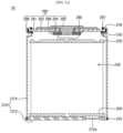
- FIG. 1A is a cross-sectional view of a cylindrical secondary battery according to an embodiment
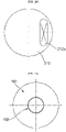
- FIG. 1B is a plan view illustrating a bottom part and a notch of the cylindrical secondary battery illustrated in FIG. 1A
- FIG. 1C is a cross-sectional view illustrating the bottom part and the notch of a cylindrical secondary battery according to another embodiment.
- a cylindrical secondary battery 10 may include a cylindrical can 110, an electrode assembly 130 inserted into (or accommodated in) the can 110, a cap assembly 190 coupled to one end of the can 110, and first and second electrode collecting plates 150 and 170 electrically connecting the electrode assembly 130 to the cap assembly 190.
- the cap assembly 190 will be described later.
- the can 110 has a circular bottom part 112 and a side part 114 extending upwardly from the bottom part 112.
- the side part 114 has a cylindrical shape with an open top end (hereinafter, referred to as an opening).
- the electrode assembly 130 is inserted into the can 110 together with an electrolyte through the opening in the can 110.
- the electrode assembly 130 may be electrically connected to the can 110 and the cap assembly 190 by the first electrode collecting plate 150 and the second electrode collecting plate 170, respectively.
- the can 110 may be made of steel, a steel alloy, nickel-plated steel, nickel-plated steel alloy, aluminium, an aluminium alloy, or an equivalent thereof, but the material thereof is not limited thereto.
- a notch 112a may be provided in (or formed in) the bottom part 112 to act as a vent.
- the notch 112a may have a circular shape with a diameter (e.g., a predetermined diameter) in the circular bottom part 112.
- the notch 112a may be concavely formed in (e.g., may be recessed from) an inner surface of the bottom part 112 (e.g., a plate surface facing the inside of the can 110) through internal press processing.
- a notch 112b may be concavely formed in each of an inner surface and an outer surface (e.g., a plate surface facing the outside of the can) of the bottom part 112' by performing the press processing on the inside and outside of the bottom part 112'.
- a notch 112c may be formed in an outer surface of the bottom part 112" through external press processing.
- the notches 112a, 112b, and/or 112c each of which is thinner than each of the other portions of the bottom part 112 (e.g., each of which is a thinned portion of the bottom part 112 of the can 110), 112', and 112", breaks (or cracks or bursts), and thus, the gas, the electrode plate, the active material, and the like may be discharged to the outside of the can 110.
- the notch 112a, 112b, and/or 112c act as vents to prevent the secondary battery 10 from exploding (e.g., from an uncontrolled explosion).
- a vent may be omitted from the cap assembly 190, which will be described later.
- a beading part e.g., a bead or bead portion
- a beading part 116 concavely formed inwardly from (or on) an outer circumferential surface of the side part 114 may be disposed adjacent to the opening in the side part 114.
- an upper end of the can 110 is bent inwardly to fix the cap assembly 190 to the can 110.
- an end of a crimping part 118 may be electrically connected to the cap assembly 190, which will be described later.
- the cap assembly 190 may be coupled to the can 110 at the opening therein to close and seal the opening.
- the electrode assembly 130 includes a first electrode plate, a second electrode plate, and a separator.
- the first electrode plate may be a negative electrode plate on which a negative electrode active material layer (e.g., graphite, carbon, etc.) is disposed on both surfaces (e.g., opposite surfaces) thereof.
- a first electrode non-coating portion to which the negative electrode active material layer is not applied may be a portion of the first electrode plate.
- the second electrode plate may be a positive electrode plate on which a positive electrode active material layer (e.g., transition metal oxide (LiCoO 2 , LiNiO 2 , LiMn 2 O 4 , etc.)) is disposed on both surfaces (e.g., opposite surfaces) thereof.
- a positive electrode active material layer e.g., transition metal oxide (LiCoO 2 , LiNiO 2 , LiMn 2 O 4 , etc.
- a second electrode non-coating portion to which the positive electrode active material layer is not applied may be a portion of the second electrode plate.
- the separator may be interposed between the first electrode plate and the second electrode plate to prevent a short circuit from occurring thereby while allowing lithium ions to move.
- the first electrode plate may be made of copper (Cu) or nickel (Ni) foil
- the second electrode plate may be made of aluminium (Al) foil
- the separator may be made of polyethylene (PE) or polypropylene (PP), but the present disclosure is not limited thereto.
- the first electrode plate, the second electrode plate, and the separator may be wound in a substantially cylindrical shape and accommodated in the can 110.
- the first electrode plate and the second electrode plate may be disposed so that the first and second electrode non-coating portions, to which the active material is not applied, are opposite to each other in the winding.
- the first electrode plate which is the negative electrode plate
- the second electrode plate which is a positive electrode plate
- the separator may be disposed between the first electrode plate and the second electrode plate and wound in a state in which the separator insulates the first and second electrode plates from each other.
- the first electrode collecting plate 150 may be electrically connected to the first electrode non-coating portion
- the second electrode collecting plate 170 may be electrically connected to the second electrode non-coating portion.
- the can 110 and the cap assembly 190 are electrically connected to the electrode assembly 130.
- the first electrode collecting plate 150 may be electrically connected to the bottom part 112 of the can 110 via welding or the like. Since the first electrode collecting plate 150 is electrically connected to the first electrode non-coating portion, the first electrode collecting plate 150 may be defined as a negative electrode collecting plate.
- the second electrode collecting plate 170 may be electrically connected to the cap assembly 190 by a collecting lead 180. Because the second electrode collecting plate 170 is electrically connected to the second electrode non-coating portion, the second electrode collecting plate 170 may be referred to as a positive electrode collecting plate.
- the cap assembly 190 may include a cap plate 191, a rivet terminal 192 coupled to a center of the cap plate 191, an insulator 193 insulating the rivet terminal 192 from the cap plate 191, and a stopper 196 fixing the rivet terminal 192.
- the components and/or structure of the insulator may vary according to embodiments.
- the stopper 196 may be omitted.
- the cap plate 191 is substantially disk shaped and has an opening (e.g., a hole) into which the rivet terminal 192 in the center of the cap plate 191 is inserted.
- the cap plate 191 may be made of a nickel-plated material or a SUS material on a cold rolled steel sheet, such as SPCE.
- the cap plate 191 may be seated on the beading part 116.
- An outer edge of the cap plate 191 may be insulated from the side part 114 of the can 110 by a gasket 198.
- An inner edge of (e.g., an edge of the opening in) the cap plate 191 may be insulated from the rivet terminal 192 by the insulator 193.
- the rivet terminal 192 is inserted into the opening in the cap plate 191 and may be electrically connected to the second electrode collecting plate 170, which is a positive electrode collecting plate, by the collecting lead 180.
- the rivet terminal 192 may be made of the same or a similar material as the collecting lead 180 or the second electrode collecting plate 170.
- a portion of the rivet terminal 192 exposed to an upper portion of (e.g., on an outer surface of) the cap plate 191 may have a diameter greater than that of a portion thereof inserted into the opening in the cap plate 191 (e.g., a portion of the rivet terminal 192 on an inner surface of the cap plate 191).
- the portion of the rivet terminal 192 that is exposed to the upper portion of the cap plate 191 is referred to as an upper end of the rivet terminal 192
- a portion of the rivet terminal 192 that faces the second electrode collecting plate 170 is referred to as a lower end of the rivet terminal 192.
- the lower end of the rivet terminal 192 may be compression-deformed (e.g., compression-molded) by a processing method, such as pressing or spinning, to be in close contact with a bottom surface (or inner surface) of the cap plate 191.
- a hollow ring-shaped stopper 196 may be additionally provided.
- the press or spinning processing may be performed when the stopper 196 is inserted into (or onto) the lower end of the rivet terminal 192.
- the lower end of the rivet terminal 192 is compressed and deformed to be in close contact with the stopper 196 and to be in close contact with the cap plate 191 together with the stopper 196.
- the stopper 196 may also be in close contact with the insulator 193.
- the gasket 198 may be made of an insulating material and may be arranged to surround (or extend around) an outer edge and a portion of a bottom surface of the cap plate 191 but may not extend to a top surface (or outer surface) of the cap plate 191. Thus, when the crimping part 118 is formed when the cap plate 191 is seated on an upper portion of the beading part 116 with the gasket 198 therebetween, the crimping part 118 may contact the top surface of the cap plate 191.
- the can 110 and the cap plate 191 are electrically connected to each other by welding an end of the crimping part 118 to the cap plate 191 to form a welding part (e.g., a weld or a weld bead) 197.
- a resin-based material may be applied around the welding part 197 to prevent rust from occurring.
- the cap plate 191 may be electrically connected to the can 110, which is electrically connected to the first electrode collecting plate 150, which is the negative electrode collecting plate, by the welding portion 197, and thus, may have a negative polarity.
- the cap plate 191 acts as the negative electrode
- the rivet terminal 192 acts as the positive electrode
- both the positive and negative electrodes are provided in the cap assembly 190.
- a cylindrical secondary battery according to another embodiment may have a can with a structure different from that of the secondary battery 10 illustrated in FIG. 1A .
- FIG. 2A is a cross-sectional view of a cylindrical secondary battery according to another embodiment
- FIG. 2B is a plan view illustrating a bottom part and a notch of the cylindrical secondary battery illustrated in FIG. 2A .
- features that are the same or substantially similar to those described above may not be described again.
- a cylindrical secondary battery 20 may include a cylindrical can 210, an electrode assembly 230 inserted into (or accommodated in) the can 210, a cap assembly 290 coupled to one end of the can 210, and first and second electrode collecting plates 250 and 270 electrically connecting the electrode assembly 230 to the cap assembly 290.
- the can 210 may include a separately provided circular bottom part 212 and a cylindrical side part 214 having opened upper and lower sides (or ends).
- the cap assembly 290 is coupled to the opened upper end of the side part 214, and the bottom part 212 is coupled to the opened lower end of the side part 214.
- An outer edge of the bottom part 212 may be welded to the side part 214, forming a welding part 215 such that the bottom part 212 and the side part 214 are electrically connected to each other.
- the can 210 may be electrically connected to the cap assembly 290 by welding the end of the beading part 218 and the cap plate 291 to form a welding portion 297.
- a vent 212a may be provided in the bottom part 212.
- the vent 212a may be separately provided (or separately formed) and coupled and welded to a through-hole, which passes through the bottom part 212 (see, e.g., FIG. 2B ).
- the cap assemblies 190 and 290 may have various structures.
- FIGS. 3A and 3B are plan views illustrating a terminal of the cap assembly according to embodiments of the present disclosure.
- FIGS. 4A to 4C are schematic cross-sectional views of a cap assembly according to various embodiments. For convenience, reference numerals are denoted based on the embodiment of FIG. 1A .
- an upper end of the rivet terminal 192 coupled to the cap plate 191 may have a circular shape.
- an upper end of a rivet terminal 192' coupled to the cap plate 191' may be a square shape.
- these shapes of the rivet terminal are merely examples and the rivet terminal is not limited to the above-described shapes.
- FIG. 4A is a detailed cross-sectional view of the cap assembly 190 illustrated in FIG. 1A .
- a bottom surface of the upper end of the rivet terminal 192 may have a protrusion 192a protruding toward the cap plate 191.
- the insulator of the cap assembly 190 may be made of a PE or PP material and may include an upper insulator 193 and a lower insulator 194.
- An accommodation groove 1930 into which the protrusion 192a is accommodated may be defined in a top surface of the upper insulator 193.
- the protrusion 192a may be disposed adjacent to a portion of the rivet terminal 192 that is inserted into and passing through the cap plate 191.
- the rivet terminal 192 and the upper insulator 193 may be more securely coupled by the protrusion 192a and the accommodation groove 1930.
- the upper insulator 193 may have a circular plate shape in which an opening corresponding to the opening in the cap plate 191 is defined. A hollow-side inner edge of the upper insulator 193 may extend downwardly toward the second electrode collecting plate 170.
- the circular plate portion of the upper insulator 193 contacts a bottom surface of the upper end of the rivet terminal 192 to insulate the cap plate 191 from the upper end of the rivet terminal 192. Accordingly, the circular plate portion of the upper insulator 193 may have a size greater than that of the upper end of the rivet terminal 192.
- the circular plate portion of the upper insulator 193 may have a size (e.g., a diameter) less or greater than that of the circular plate portion of the lower insulator 194. A downwardly extending portion of the upper insulator 193 is inserted into the opening in the cap plate 191 to insulate the cap plate 191 from the rivet terminal 192.
- the lower insulator 194 may be disposed to be symmetrical to the upper insulator 193 and may have a shape similar to that of the upper insulator 193.
- the lower insulator 194 may have a circular plate shape in which an opening corresponding to the opening in the cap plate 191 is defined.
- a hollow-side inner edge of the lower insulator 194 may extend toward the upper insulator 193.
- the circular plate portion of the lower insulator 194 contacts a top surface of the stopper 196 to insulate the cap plate 191 from the stopper 196.
- the circular plate portion of the lower insulator 194 may have a size (e.g., a diameter) greater than that of the stopper 196 and less than that of the cap plate 191.
- An upwardly extending portion of the lower insulator 194 is inserted into the opening in the cap plate 191 to insulate the cap plate 191 from the rivet terminal 192. Extending ends of the upper insulator 193 and the lower insulator 194 may be connected to each other through an adhesive or the like or may be pressed to be in close contact with each other during the compression molding of the rivet terminal 192.
- the stopper 196 may have an inclined shape in which a diameter of the inner edge (e.g., a diameter of the opening therein) gradually increases from the top surface to the bottom surface thereof.
- a position of the lower end of the rivet terminal 192 before the process of compression-molding and fixing the rivet terminal 192 is shown in FIG. 4A by the dotted line.
- the rivet terminal 192 may be pressed upwardly from the position of the dotted line.
- the inside of the stopper 196 is inclined, the lower end of the rivet terminal 192 is spread along the shape of the inner edge of the stopper 196 while being compression-molded.
- a contact area between the rivet terminal 192 and the stopper 196 may increase to improve the coupling force of the rivet terminal 192.
- the stopper 196 may be made of a material that is the same as or similar to that of the rivet terminal 192.
- the above-described collecting lead 180 may be electrically connected to the rivet terminal 192 or electrically connected to the stopper 196 according to various embodiments.
- FIG. 4B illustrates an embodiment similar to the embodiment illustrated in FIG. 4A but in which an insulator has a different structure.
- the insulator may include an upper insulator 193a, an inner insulator 195a, and a lower insulator 194a.
- the upper insulator 193a may have a hollow circular plate shape. An outer edge of an upper portion of the inner insulator 195a may be disposed to be in close contact with an opening in the upper insulator 193a.
- the inner insulator 195a may be made of a PE, PP, or PFA material and may have cylindrical upper and lower ends, which are bent toward the upper insulator 193a and the lower insulator 194a, respectively, to extend by a length (e.g., a predetermined length).
- the lower insulator 194a may have a hollow circular plate shape, and an outer edge of a lower portion of the inner insulator 195a may be disposed to be in close contact with an opening in the lower insulator 194a.
- FIG. 4C illustrates an embodiment that is similar to the embodiment illustrated in FIG. 4B but in which an insulator has a different structure and a stopper is omitted.
- the insulator may include an upper insulator 193b and a lower insulator 194b.
- the upper insulator 193b may have a form in which the upper insulator 193a and the inner insulator 195a shown in FIG. 3B are integrated with each other.
- the upper insulator 193b may have a cylindrical shape that is integrated with a hollow circular plate-shaped portion.
- the cylindrical portion may be inserted into the opening in the cap plate 191.
- a lower end of the cylindrical portion may be bent toward the lower insulator 194b to extend by a length (e.g., a predetermined length).
- the lower insulator 194b may also have a hollow circular plate shape, and an outer edge of a lower portion of the upper insulator 193b may be disposed to be in close contact with the opening in the cap plate 191.
- the stopper may be omitted, and the rivet terminal 192' may have a rib 1920.
- the rib 1920 may extend from the lower end of the rivet terminal 192' in a substantially cylindrical shape.
- the rib 1920 may be deformed outwardly along an arrow direction to be in close contact with the lower insulator 194b.
- FIG. 4C illustrates a shape of the rib 1920, and a process of deforming the rib 1920 is illustrated in FIG. 4C by the dotted line. Due to this structure, the rivet terminal 192' may be more firmly coupled to the cap plate 191 without a separate stopper.
- the shapes of the rivet terminals 192 and 192' illustrated in FIGS. 3A and 3B may be applied to both the secondary batteries 10 and 20 illustrated in FIGS. 1A and 2A .
- the structures of the cap assemblies 190, 190a, and 190b illustrated in FIGS. 4A to 4C may also be applied to the secondary batteries 10 and 20 illustrated in FIGS. 1A and 2A .
- any one of the insulator structures illustrated in FIGS. 4A to 4C may be applied, and the structure illustrated in FIG. 4C may be applied to the structure of the rivet terminal 192'.
- both the positive electrode and the negative electrode are disposed in the (e.g., face in ) one direction of the secondary battery, the welding of the secondary battery with the bus bar may be relatively easy, and the connection structure of the bus bar may be simplified. In addition, because the welding area is widened by the rivet-type terminal structure, weldability with the bus bar may be improved.
- the welding with the bus bar may be relatively easy and the connection structure of the bus bar may be simplified.
Landscapes
- Chemical & Material Sciences (AREA)
- Chemical Kinetics & Catalysis (AREA)
- Electrochemistry (AREA)
- General Chemical & Material Sciences (AREA)
- Engineering & Computer Science (AREA)
- Manufacturing & Machinery (AREA)
- Sealing Battery Cases Or Jackets (AREA)
- Connection Of Batteries Or Terminals (AREA)
- Secondary Cells (AREA)
- Surgical Instruments (AREA)
Applications Claiming Priority (1)
| Application Number | Priority Date | Filing Date | Title |
|---|---|---|---|
| KR1020210121009A KR102601042B1 (ko) | 2021-09-10 | 2021-09-10 | 원통형 이차전지 |
Publications (1)
| Publication Number | Publication Date |
|---|---|
| EP4148879A1 true EP4148879A1 (fr) | 2023-03-15 |
Family
ID=83232653
Family Applications (1)
| Application Number | Title | Priority Date | Filing Date |
|---|---|---|---|
| EP22194449.9A Pending EP4148879A1 (fr) | 2021-09-10 | 2022-09-07 | Batterie secondaire cylindrique |
Country Status (4)
| Country | Link |
|---|---|
| US (1) | US12580260B2 (fr) |
| EP (1) | EP4148879A1 (fr) |
| KR (2) | KR102601042B1 (fr) |
| CN (1) | CN115799591B (fr) |
Cited By (3)
| Publication number | Priority date | Publication date | Assignee | Title |
|---|---|---|---|---|
| EP4199199A1 (fr) * | 2021-12-15 | 2023-06-21 | Samsung SDI Co., Ltd. | Batterie secondaire |
| WO2025132882A1 (fr) * | 2023-12-21 | 2025-06-26 | Northvolt Ab | Accumulateur |
| EP4675772A1 (fr) * | 2024-07-03 | 2026-01-07 | Samsung Sdi Co., Ltd. | Batterie secondaire |
Families Citing this family (9)
| Publication number | Priority date | Publication date | Assignee | Title |
|---|---|---|---|---|
| KR20240156729A (ko) * | 2023-04-24 | 2024-10-31 | 삼성에스디아이 주식회사 | 원통형 이차전지 |
| CN219717052U (zh) * | 2023-05-31 | 2023-09-19 | 湖北亿纬动力有限公司 | 顶盖组件及电池 |
| CN120077516A (zh) * | 2023-08-03 | 2025-05-30 | 株式会社Lg新能源 | 电池电芯和制造电池电芯的方法 |
| KR20250123543A (ko) * | 2024-02-08 | 2025-08-18 | 삼성에스디아이 주식회사 | 원통형 이차전지 |
| KR20250150863A (ko) * | 2024-04-12 | 2025-10-21 | 삼성에스디아이 주식회사 | 이차 전지 |
| WO2025220847A1 (fr) * | 2024-04-16 | 2025-10-23 | 삼성에스디아이(주) | Batterie secondaire et bloc-batterie comprenant celle-ci |
| KR20250152303A (ko) * | 2024-04-16 | 2025-10-23 | 삼성에스디아이 주식회사 | 배터리 셀 |
| CN121794834A (zh) * | 2024-05-24 | 2026-04-03 | 株式会社Lg新能源 | 能够底部冷却的圆柱形电池电芯 |
| KR20260038425A (ko) * | 2024-09-12 | 2026-03-19 | 삼성에스디아이 주식회사 | 리벳을 포함하는 이차전지 및 이차전지의 제조 방법 |
Citations (4)
| Publication number | Priority date | Publication date | Assignee | Title |
|---|---|---|---|---|
| US6132900A (en) * | 1996-12-25 | 2000-10-17 | Matsushita Electric Industrial Co., Ltd. | Method of production of non-aqueous electrolyte battery and seal plate thereof |
| US20110223449A1 (en) * | 2004-07-23 | 2011-09-15 | Saft | Safety device for a sealed cell |
| US20130095353A1 (en) * | 2011-10-18 | 2013-04-18 | Johnson Controls Technology Llc | Electrochemical cell having a safety device |
| KR20210053105A (ko) * | 2019-11-01 | 2021-05-11 | 주식회사 엘지화학 | 이차전지 |
Family Cites Families (18)
| Publication number | Priority date | Publication date | Assignee | Title |
|---|---|---|---|---|
| KR19990041759A (ko) * | 1997-11-24 | 1999-06-15 | 손욱 | 이차전지의 캡 어셈블리 |
| KR100467703B1 (ko) * | 2002-10-21 | 2005-01-24 | 삼성에스디아이 주식회사 | 캡 조립체 및 이를 채용한 이차전지 |
| KR100522819B1 (ko) * | 2003-08-18 | 2005-10-18 | 삼성에스디아이 주식회사 | 리튬 이온 2차 전지 |
| KR100973423B1 (ko) * | 2006-10-16 | 2010-08-02 | 주식회사 엘지화학 | 안전성이 향상된 원통형 전지 |
| KR20110056117A (ko) | 2009-11-20 | 2011-05-26 | 삼성에스디아이 주식회사 | 원통형 이차 전지 |
| KR101184403B1 (ko) | 2010-10-21 | 2012-09-19 | 주식회사 엘지화학 | 캡 조립체 및 이를 이용한 이차 전지 |
| KR101292534B1 (ko) | 2011-09-27 | 2013-08-09 | 상신이디피(주) | 원통형 이차전지 캔의 안전 벤트 |
| JP6117927B2 (ja) * | 2013-08-22 | 2017-04-19 | 日立オートモティブシステムズ株式会社 | 二次電池 |
| KR101593532B1 (ko) | 2014-03-14 | 2016-02-15 | 엘에스엠트론 주식회사 | 내부 터미널 구조가 개선된 전기에너지 저장장치 및 이를 위한 내부 터미널 구조 |
| KR20160015778A (ko) | 2014-07-31 | 2016-02-15 | 주식회사 엘지화학 | 내진동 특성이 향상된 원통형 전지 |
| KR102635156B1 (ko) | 2016-04-22 | 2024-02-08 | 삼성에스디아이 주식회사 | 이차 전지 |
| KR102246483B1 (ko) * | 2016-10-21 | 2021-04-30 | 주식회사 엘지화학 | 측면 벤트를 포함하는 원통형 전지 |
| JP6868400B2 (ja) * | 2017-01-17 | 2021-05-12 | Fdk株式会社 | 筒型電池の封口体、筒型電池 |
| KR102263435B1 (ko) | 2017-09-13 | 2021-06-11 | 주식회사 엘지에너지솔루션 | 비딩부가 생략된 원통형 전지셀 |
| JP6996308B2 (ja) * | 2018-01-17 | 2022-01-17 | 三洋電機株式会社 | 二次電池及びその製造方法 |
| KR102570969B1 (ko) | 2018-02-01 | 2023-08-25 | 삼성에스디아이 주식회사 | 원통형 리튬 이온 이차 전지 |
| CN117597810A (zh) * | 2021-07-12 | 2024-02-23 | 合肥国轩高科动力能源有限公司 | 圆柱形电池单元、电池和用于形成圆柱形电池单元的方法 |
| KR102561215B1 (ko) * | 2021-12-15 | 2023-07-28 | 삼성에스디아이 주식회사 | 이차 전지 |
-
2021
- 2021-09-10 KR KR1020210121009A patent/KR102601042B1/ko active Active
-
2022
- 2022-09-07 US US17/939,810 patent/US12580260B2/en active Active
- 2022-09-07 EP EP22194449.9A patent/EP4148879A1/fr active Pending
- 2022-09-08 CN CN202211097542.6A patent/CN115799591B/zh active Active
-
2023
- 2023-11-07 KR KR1020230152620A patent/KR102806599B1/ko active Active
Patent Citations (4)
| Publication number | Priority date | Publication date | Assignee | Title |
|---|---|---|---|---|
| US6132900A (en) * | 1996-12-25 | 2000-10-17 | Matsushita Electric Industrial Co., Ltd. | Method of production of non-aqueous electrolyte battery and seal plate thereof |
| US20110223449A1 (en) * | 2004-07-23 | 2011-09-15 | Saft | Safety device for a sealed cell |
| US20130095353A1 (en) * | 2011-10-18 | 2013-04-18 | Johnson Controls Technology Llc | Electrochemical cell having a safety device |
| KR20210053105A (ko) * | 2019-11-01 | 2021-05-11 | 주식회사 엘지화학 | 이차전지 |
Cited By (4)
| Publication number | Priority date | Publication date | Assignee | Title |
|---|---|---|---|---|
| EP4199199A1 (fr) * | 2021-12-15 | 2023-06-21 | Samsung SDI Co., Ltd. | Batterie secondaire |
| US12469911B2 (en) | 2021-12-15 | 2025-11-11 | Samsung Sdi Co., Ltd. | Secondary battery |
| WO2025132882A1 (fr) * | 2023-12-21 | 2025-06-26 | Northvolt Ab | Accumulateur |
| EP4675772A1 (fr) * | 2024-07-03 | 2026-01-07 | Samsung Sdi Co., Ltd. | Batterie secondaire |
Also Published As
| Publication number | Publication date |
|---|---|
| US12580260B2 (en) | 2026-03-17 |
| KR102806599B1 (ko) | 2025-05-13 |
| CN115799591B (zh) | 2026-04-07 |
| KR20230037895A (ko) | 2023-03-17 |
| KR20230158443A (ko) | 2023-11-20 |
| US20230079718A1 (en) | 2023-03-16 |
| CN115799591A (zh) | 2023-03-14 |
| KR102601042B1 (ko) | 2023-11-13 |
Similar Documents
| Publication | Publication Date | Title |
|---|---|---|
| EP4148879A1 (fr) | Batterie secondaire cylindrique | |
| US20230231242A1 (en) | Secondary battery | |
| KR102571628B1 (ko) | 이차 전지 | |
| US20230253568A1 (en) | Secondary battery | |
| US20240274933A1 (en) | Cylindrical secondary battery | |
| US20260066491A1 (en) | Secondary battery | |
| EP4258434A1 (fr) | Batterie secondaire cylindrique | |
| EP4216363A1 (fr) | Batterie secondaire cylindrique | |
| EP4362178A1 (fr) | Batterie secondaire cylindrique | |
| EP4372857A2 (fr) | Batterie secondaire cylindrique | |
| US20250246787A1 (en) | Secondary battery | |
| EP4354605A1 (fr) | Batterie secondaire cylindrique | |
| KR20180080847A (ko) | 이차 전지 | |
| EP4216348A1 (fr) | Batterie secondaire | |
| KR102824566B1 (ko) | 원통형 이차전지 | |
| KR102950675B1 (ko) | 원통형 이차 전지 | |
| US20260074356A1 (en) | Cap assembly, secondary battery including cap assembly, and method of manufacturing cap assembly | |
| KR20240174615A (ko) | 이차전지 |
Legal Events
| Date | Code | Title | Description |
|---|---|---|---|
| PUAI | Public reference made under article 153(3) epc to a published international application that has entered the european phase |
Free format text: ORIGINAL CODE: 0009012 |
|
| STAA | Information on the status of an ep patent application or granted ep patent |
Free format text: STATUS: REQUEST FOR EXAMINATION WAS MADE |
|
| 17P | Request for examination filed |
Effective date: 20220907 |
|
| AK | Designated contracting states |
Kind code of ref document: A1 Designated state(s): AL AT BE BG CH CY CZ DE DK EE ES FI FR GB GR HR HU IE IS IT LI LT LU LV MC MK MT NL NO PL PT RO RS SE SI SK SM TR |
|
| P01 | Opt-out of the competence of the unified patent court (upc) registered |
Effective date: 20230712 |