EP4148979A1 - Ensemble photovoltaïque pliable pour un système d'énergie solaire portable - Google Patents
Ensemble photovoltaïque pliable pour un système d'énergie solaire portable Download PDFInfo
- Publication number
- EP4148979A1 EP4148979A1 EP21196430.9A EP21196430A EP4148979A1 EP 4148979 A1 EP4148979 A1 EP 4148979A1 EP 21196430 A EP21196430 A EP 21196430A EP 4148979 A1 EP4148979 A1 EP 4148979A1
- Authority
- EP
- European Patent Office
- Prior art keywords
- support element
- photovoltaic
- photovoltaic assembly
- major surface
- articulated
- Prior art date
- Legal status (The legal status is an assumption and is not a legal conclusion. Google has not performed a legal analysis and makes no representation as to the accuracy of the status listed.)
- Withdrawn
Links
Images


Classifications
-
- H—ELECTRICITY
- H02—GENERATION; CONVERSION OR DISTRIBUTION OF ELECTRIC POWER
- H02S—GENERATION OF ELECTRIC POWER BY CONVERSION OF INFRARED RADIATION, VISIBLE LIGHT OR ULTRAVIOLET LIGHT, e.g. USING PHOTOVOLTAIC [PV] MODULES
- H02S20/00—Supporting structures for PV modules
- H02S20/10—Supporting structures directly fixed to the ground
-
- H—ELECTRICITY
- H02—GENERATION; CONVERSION OR DISTRIBUTION OF ELECTRIC POWER
- H02S—GENERATION OF ELECTRIC POWER BY CONVERSION OF INFRARED RADIATION, VISIBLE LIGHT OR ULTRAVIOLET LIGHT, e.g. USING PHOTOVOLTAIC [PV] MODULES
- H02S30/00—Structural details of PV modules other than those related to light conversion
- H02S30/20—Collapsible or foldable PV modules
-
- F—MECHANICAL ENGINEERING; LIGHTING; HEATING; WEAPONS; BLASTING
- F24—HEATING; RANGES; VENTILATING
- F24S—SOLAR HEAT COLLECTORS; SOLAR HEAT SYSTEMS
- F24S20/00—Solar heat collectors specially adapted for particular uses or environments
- F24S20/50—Rollable or foldable solar heat collector modules
-
- F—MECHANICAL ENGINEERING; LIGHTING; HEATING; WEAPONS; BLASTING
- F24—HEATING; RANGES; VENTILATING
- F24S—SOLAR HEAT COLLECTORS; SOLAR HEAT SYSTEMS
- F24S25/00—Arrangement of stationary mountings or supports for solar heat collector modules
- F24S25/10—Arrangement of stationary mountings or supports for solar heat collector modules extending in directions away from a supporting surface
-
- F—MECHANICAL ENGINEERING; LIGHTING; HEATING; WEAPONS; BLASTING
- F24—HEATING; RANGES; VENTILATING
- F24S—SOLAR HEAT COLLECTORS; SOLAR HEAT SYSTEMS
- F24S25/00—Arrangement of stationary mountings or supports for solar heat collector modules
- F24S25/20—Peripheral frames for modules
-
- F—MECHANICAL ENGINEERING; LIGHTING; HEATING; WEAPONS; BLASTING
- F24—HEATING; RANGES; VENTILATING
- F24S—SOLAR HEAT COLLECTORS; SOLAR HEAT SYSTEMS
- F24S25/00—Arrangement of stationary mountings or supports for solar heat collector modules
- F24S25/60—Fixation means, e.g. fasteners, specially adapted for supporting solar heat collector modules
- F24S25/63—Fixation means, e.g. fasteners, specially adapted for supporting solar heat collector modules for fixing modules or their peripheral frames to supporting elements
- F24S25/632—Side connectors; Base connectors
-
- F—MECHANICAL ENGINEERING; LIGHTING; HEATING; WEAPONS; BLASTING
- F24—HEATING; RANGES; VENTILATING
- F24S—SOLAR HEAT COLLECTORS; SOLAR HEAT SYSTEMS
- F24S25/00—Arrangement of stationary mountings or supports for solar heat collector modules
- F24S25/60—Fixation means, e.g. fasteners, specially adapted for supporting solar heat collector modules
- F24S25/65—Fixation means, e.g. fasteners, specially adapted for supporting solar heat collector modules for coupling adjacent supporting elements, e.g. for connecting profiles together
-
- F—MECHANICAL ENGINEERING; LIGHTING; HEATING; WEAPONS; BLASTING
- F24—HEATING; RANGES; VENTILATING
- F24S—SOLAR HEAT COLLECTORS; SOLAR HEAT SYSTEMS
- F24S25/00—Arrangement of stationary mountings or supports for solar heat collector modules
- F24S25/60—Fixation means, e.g. fasteners, specially adapted for supporting solar heat collector modules
- F24S25/67—Fixation means, e.g. fasteners, specially adapted for supporting solar heat collector modules for coupling adjacent modules or their peripheral frames
-
- H—ELECTRICITY
- H02—GENERATION; CONVERSION OR DISTRIBUTION OF ELECTRIC POWER
- H02S—GENERATION OF ELECTRIC POWER BY CONVERSION OF INFRARED RADIATION, VISIBLE LIGHT OR ULTRAVIOLET LIGHT, e.g. USING PHOTOVOLTAIC [PV] MODULES
- H02S10/00—PV power plants; Combinations of PV energy systems with other systems for the generation of electric power
- H02S10/40—Mobile PV generator systems
-
- H—ELECTRICITY
- H02—GENERATION; CONVERSION OR DISTRIBUTION OF ELECTRIC POWER
- H02S—GENERATION OF ELECTRIC POWER BY CONVERSION OF INFRARED RADIATION, VISIBLE LIGHT OR ULTRAVIOLET LIGHT, e.g. USING PHOTOVOLTAIC [PV] MODULES
- H02S20/00—Supporting structures for PV modules
-
- H—ELECTRICITY
- H02—GENERATION; CONVERSION OR DISTRIBUTION OF ELECTRIC POWER
- H02S—GENERATION OF ELECTRIC POWER BY CONVERSION OF INFRARED RADIATION, VISIBLE LIGHT OR ULTRAVIOLET LIGHT, e.g. USING PHOTOVOLTAIC [PV] MODULES
- H02S20/00—Supporting structures for PV modules
- H02S20/30—Supporting structures being movable or adjustable, e.g. for angle adjustment
- H02S20/32—Supporting structures being movable or adjustable, e.g. for angle adjustment specially adapted for solar tracking
-
- F—MECHANICAL ENGINEERING; LIGHTING; HEATING; WEAPONS; BLASTING
- F24—HEATING; RANGES; VENTILATING
- F24S—SOLAR HEAT COLLECTORS; SOLAR HEAT SYSTEMS
- F24S25/00—Arrangement of stationary mountings or supports for solar heat collector modules
- F24S2025/01—Special support components; Methods of use
- F24S2025/012—Foldable support elements
-
- Y—GENERAL TAGGING OF NEW TECHNOLOGICAL DEVELOPMENTS; GENERAL TAGGING OF CROSS-SECTIONAL TECHNOLOGIES SPANNING OVER SEVERAL SECTIONS OF THE IPC; TECHNICAL SUBJECTS COVERED BY FORMER USPC CROSS-REFERENCE ART COLLECTIONS [XRACs] AND DIGESTS
- Y02—TECHNOLOGIES OR APPLICATIONS FOR MITIGATION OR ADAPTATION AGAINST CLIMATE CHANGE
- Y02E—REDUCTION OF GREENHOUSE GAS [GHG] EMISSIONS, RELATED TO ENERGY GENERATION, TRANSMISSION OR DISTRIBUTION
- Y02E10/00—Energy generation through renewable energy sources
- Y02E10/40—Solar thermal energy, e.g. solar towers
- Y02E10/47—Mountings or tracking
-
- Y—GENERAL TAGGING OF NEW TECHNOLOGICAL DEVELOPMENTS; GENERAL TAGGING OF CROSS-SECTIONAL TECHNOLOGIES SPANNING OVER SEVERAL SECTIONS OF THE IPC; TECHNICAL SUBJECTS COVERED BY FORMER USPC CROSS-REFERENCE ART COLLECTIONS [XRACs] AND DIGESTS
- Y02—TECHNOLOGIES OR APPLICATIONS FOR MITIGATION OR ADAPTATION AGAINST CLIMATE CHANGE
- Y02E—REDUCTION OF GREENHOUSE GAS [GHG] EMISSIONS, RELATED TO ENERGY GENERATION, TRANSMISSION OR DISTRIBUTION
- Y02E10/00—Energy generation through renewable energy sources
- Y02E10/50—Photovoltaic [PV] energy
Definitions
- the present invention relates to the field of portable solar energy systems.
- the present invention relates to the field of photovoltaic assemblies which ease the transport and installation of photovoltaic laminates (photovoltaic surface without a complete peripheral frame) for a solar energy collection system.
- the invention provides a photovoltaic assembly for a portable solar system.
- Photovoltaic panels or laminates are widely used to generate electricity from sunlight. Photovoltaic panels or laminates are usually fixed on surfaces like roofs, building facades, on the ground, etc. using supporting structures, which may be known as photovoltaic mounting systems or solar module racking, among others. Such structures may differ depending on whether they support photovoltaic panels or photovoltaic laminates, as they are designed to be attached to their supporting structures in different ways, the main reason being that photovoltaic panels usually comprise a perimeter frame that provides structural integrity, whereas photovoltaic laminates usually lack any perimeter frame. Usually, photovoltaic panels are more robust than photovoltaic laminates. Supporting structures should take into account the differences between photovoltaic laminates and photovoltaic panels.
- a solar panel or laminate performs the best when its surface is substantially perpendicular to the sun's rays, which change continuously over the course of the day and season.
- the supporting structures of the photovoltaic panels or laminates are also often used to orientate the photovoltaic panels or laminates in regard to solar radiation to maximize their energy production.
- Said supporting structure may be fixed, i.e., the photovoltaic panels or laminates have a fixed orientation, or may tilt, i.e., the orientation of the photovoltaic panels or laminates may vary depending on the position of the sun.
- a solar energy system typically comprises one or more photovoltaic assemblies, which typically comprise one or more photovoltaic panels or laminates and a supporting structure.
- Photovoltaic assemblies are usually installed at locations remote from its manufacturing site. Consequently, there is a need to transport the energy system components from their manufacturing site to the installation site where they will be assembled. Therefore, it is advantageous to provide a solar energy system that can be assembled in optimal conditions off-site and easily transported, as this can provide a significant cost reduction, among other benefits.
- the photovoltaic assemblies Besides being transported from the manufacturing site, or any intermediate storage site, to the location where the solar energy system is to be installed, the photovoltaic assemblies need to be mounted or installed. Consequently, it is advantageous if the photovoltaic assemblies of a solar energy system can be easily installed, as this can provide a significant time and cost reduction, an increase in worker safety, etc.
- WO 2010/098806 A1 discloses a photovoltaic assembly comprising an array of photovoltaic laminates supported on a perimetral frame formed by top and bottom beams, side beams, and intermediate beams shared between two photovoltaic laminates, and a stiffening device formed by interconnected profiles.
- the stiffening device is configured to be transitioned between an operative position, in which the stiffening device protrudes from a lower side of the photovoltaic assembly and provides support and strengthening thereto, and a folded position, in which the stiffening device is maintained in its entirety within a receiving zone defined by the perimeter frame of the photovoltaic assembly.
- Said receiving zone is disclosed to have a height of no more than 8 inches thereby facilitating transport of the photovoltaic assembly.
- the present invention discloses a photovoltaic assembly for a portable solar energy system, the photovoltaic assembly comprising: a row of interconnected photovoltaic laminates, each photovoltaic laminate having an internal and an external major surface; a foldable stiffening and/or supporting structure comprising articulated members, the foldable stiffening or supporting structure being movable between a folded position and an operative position; wherein the photovoltaic assembly further comprises at least two support elements, each support element being attached at least to the internal major surface of two adjacent photovoltaic laminates, each support element having a closed cross-section and comprising a first lateral face perpendicular to the internal major surface of the photovoltaic laminate; and wherein one or more articulated members of the foldable stiffening and/or supporting structure are connected in an articulated manner to the first lateral face of the corresponding support
- a face of the articulated members in the folded position of the foldable stiffening and/or supporting structure a face of the articulated members may be substantially coplanar with the internal major surface of the photovoltaic laminate, that is to say, a face of the articulated members may be substantially in contact with the internal major surface of the photovoltaic laminate.
- a face of the articulated member in the folded position of the foldable stiffening and/or supporting structure a face of the articulated member may be substantially parallel to the internal major surface of the photovoltaic laminate.
- the distance between the internal surface of the photovoltaic panel and said face of the articulated member may be less than 5 cm, preferably less than 3 cm, more preferably less than 2 cm, even more preferably less than 1 cm.
- the foldable stiffening and/or supporting structure in its operative position, may be configured to support the photovoltaic assembly.
- the support element may comprise a second lateral face opposite the first one.
- two or more articulated members of the foldable stiffening and/or supporting structure may be connected in an articulated manner to the first lateral face of the support element.
- one or more articulated members of the foldable stiffening and/or supporting structure may be connected in an articulated manner to the second lateral face of the support element.
- the support element may be attached to the internal and to the external major surface of two adjacent photovoltaic laminates.
- the support element may be attached to the adjacent laminates by a T-shaped member extending from the upper side of said support element, said T-shaped member together with the upper side of the support element defining two grooves for the reception of side edges of adjacent laminates, said side edges being preferably provided with a protective cover.
- the support element may be attached to the adjacent laminates by an auxiliary member, said auxiliary member being attached to the upper side of the support element, said auxiliary member defining two grooves for the reception of side edges of adjacent laminates, said side edges being preferably provided with a protective cover.
- the support element may be attached to the adjacent laminates by a corresponding auxiliary member, each auxiliary member being clipped to a corresponding projection extending parallel to the upper side of the support element, each auxiliary member together with the corresponding projection defining a groove for the reception of the side edge of the corresponding laminate, said side edge being preferably provided with a protective cover.
- the aforementioned protective cover of the side edges of photovoltaic laminates protects said laminates from forces; for example, the clamping force of the auxiliary or T-shaped members, or vibrations that could damage the photovoltaic laminate.
- the support element may further comprise a stop between the auxiliary members for limiting their movement.
- Said stop may be an extra or separate part attached to the support element or may be integral with said support element.
- the support element may define a first distance from the internal major surface of the photovoltaic laminate to the edge of the first lateral face farthest from said internal major surface in a direction perpendicularto said internal major surface; and the articulated members of the foldable stiffening and/or supporting structure, in its folded position, may define a second distance from the internal major surface to the edge of the articulated member farthest from said internal major surface in a direction perpendicular to said internal major surface; said second distance being equal or greater than said first distance.
- part of the foldable stiffening and/or supporting structure may protrude from the support element, although it is preferred that it protrudes minimally to reduce the space required for the transport of the photovoltaic assembly.
- the articulated members may be connected in an articulated manner to their corresponding support element by an interconnection pin.
- the interconnection pins comprised in the first lateral face of the support elements are mutually aligned and the interconnection pins comprised in the second lateral face of the support elements are mutually aligned.
- the interconnection pins may be mutually aligned, that is to say, all interconnection pins that connect the articulated members to their corresponding support element may define a common pivot axis.
- the foldable stiffening and/or supporting structure may comprise one or more transverse members interconnecting the articulated members.
- the one or more transverse members may comprise one or more beams.
- said one or more beams may have at least one of the following cross-sections: squared, rectangular, circular, L-shaped, or U-shaped.
- the photovoltaic assembly may further comprise transverse reinforcements connected to its support elements.
- references to geometric position such as parallel, perpendicular, tangent, etc. allow deviations up to ⁇ 5° from the theoretical position defined by this nomenclature.
- FIG. 1 shows in a perspective view a first exemplary embodiment of a photovoltaic assembly for a portable solar energy system according to the present invention, with its foldable stiffening and/or supporting structure 3 in a folded position.
- the support elements 2 comprise one articulated member 4, 5 attached at each of its lateral faces 10 (see FIG. 3 ).
- FIG, 1 the foldable stiffening and/or supporting structure 3 is depicted in its folded position, in which a face of the articulated members 4, 5 is substantially coplanar with the internal surface of the photovoltaic laminate 1. It is also possible that in other embodiments, in the folded position, a face of the articulated members 4, 5 is not substantially coplanar with the internal surface of the photovoltaic laminate 1. In the latter case, the face of the articulated member 4, 5 closer to the internal surface of the photovoltaic laminate 1 may be parallel to said internal surface of the photovoltaic laminate 1 (see FIGS. 4 to 7 ).
- FIG. 1 also shows detail views A, B, C, D, E, F, G of said first exemplary embodiment.
- the first exemplary embodiment shown comprises five interconnected photovoltaic laminates 1.
- Other embodiments of the present invention may comprise a different number of photovoltaic laminates 1, for example, two, six, ten, etc.
- the photovoltaic laminates 1 comprise an internal and an external major surface. Due to the perspective used, in FIG. 1 only the internal major surface of the photovoltaic laminates 1 can be seen.
- the foldable stiffening and/or supporting structure 3 comprises reinforcing members interconnecting the articulated members 4,5.
- the reinforcing members comprise two longitudinal beams 30, each one on opposite ends following a longitudinal direction of the photovoltaic assembly, interconnecting the corresponding articulated members 4,5.
- each longitudinal beams 30 is connected or joined to the corresponding articulated member 4, 5, said beams 30 being substantially parallel to the longitudinal axis of the photovoltaic assembly, and besides increasing the structural integrity of the foldable stiffening and/or supporting structure 3, said beams 30 also increase the stability of the photovoltaic assembly when it is in its working or operative position standing on the ground or any other supporting surface.
- the beams 30 protrude from the ends of the support elements 2, thus providing a perimeter frame that protect the photovoltaic assembly, for example, when being transported or lifted, among others.
- the support elements 2 comprise one articulated member 4, 5 attached at each of its lateral faces 10 (see FIG. 3 ), which are perpendicular to the internal major surface of the corresponding laminate 1.
- These articulated members 4, 5 are pivotally attached to the corresponding support element 2 by an interconnection pin 12.
- the exemplary embodiment shown comprises support elements 2 comprising two articulated member 4, 5.
- one or more support elements 2, including the ones at the ends of the photovoltaic assembly can comprise only one articulated member 4, 5.
- Other embodiments can comprise support elements 2 comprising more than two articulated members 4, 5.
- all support elements 2 of a photovoltaic assembly comprise the same number of articulated members 4, 5, it is also possible that a photovoltaic assembly comprises support elements 2 having different numbers of articulated members 4,5, for example, two support elements 2 having two articulated members 4,5 and four support elements 2 having one articulated member 4, 5.
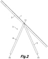
- FIG. 2 depicts in a profile view the first exemplary embodiment of a photovoltaic assembly shown in FIG. 1 , but with its stiffening and/or supporting structure 3 in an operative position.
- the foldable stiffening and/or supporting structure 3 supports the photovoltaic assembly and, in particular, the photovoltaic laminates 1, generally at a position that maximizes their energy production.
- each pair of articulated members 4, 5 are arranged to form a triangle, which rests on the ground or any other supporting surface via the beams 30.
- each lateral face 10a, 10b of the support element 2 may comprise more than one articulated member 4,5.
- the articulated members 4,5 comprise further articulated members attached to them in an articulated or pivotal manner, to create a more robust or stiff foldable stiffening and/or supporting structure 3, for example.
- Said further articulated members can also be used to form different kins of photovoltaic assembly, such as, a solar tracker.
- FIG. 3 shows a section of part of the first exemplary embodiment of a photovoltaic assembly shown in FIGS. 1 and 2 .
- FIG. 3 shows a section view of a support element 2, together with the corresponding articulated members 4, 5 and the photovoltaic laminates 1, said section being done through a plane perpendicular to the internal major surface of the laminate 1 and that cuts the interconnection pin 12 through its longitudinal axis.
- two adjacent laminates 1 are joined together and to the support section 7 of the support element 2 by means of an adhesive.
- other attaching means can be used.
- the support section 7 is defined by the top face or wall 9 of the support element 2.
- said support section 7 of the photovoltaic laminates 1 may differ.
- the support element 2 of the first exemplary embodiment shown comprises two lateral walls or faces 10 perpendicular to the internal major surface of the photovoltaic laminate 1.
- This section view clearly shows how, in this exemplary embodiment, a first articulated member 4 is connected to the first lateral face 10a of the support element 2 and a second articulated member 5 is connected to the second lateral face 10b of said support element 2.
- This section view also shows how, in this exemplary embodiment, a first distance from the internal major surface of the photovoltaic laminate 1 to the edge of the first lateral face 10a of the support element 2 is equal to a second distance from the internal major surface of the photovoltaic laminate 1 to the edge of the articulated member 4, 5 furthest from said internal major surface.
- said second distance is slightly larger than the first one, that is to say, in said embodiments the truss or reinforcing members of the foldable stiffening and/or supporting structure 3 can slightly protrude, for example., 1-2 cm or less, from the support element 2, but still providing a compact arrangement of the photovoltaic assembly when in its folded or inoperative position.
- said second distance could also be smaller than said first distance.
- the support element 2 has a closed cross section in order to provide the photovoltaic assembly with sufficient structural integrity. Even though the support element of the first exemplary embodiment shown has a rectangular cross section, in other embodiments the support element 2 can have a different cross section, i.e., squared. Although it is preferred to have homogeneity, it is also possible that not all support elements 2 of a photovoltaic assembly have the same cross section.
- the support element 2 is hollow. However, in other embodiments the support element 2 can be solid, i.e., not hollow.
- FIG. 4 shows a section view of part of a second exemplary embodiment of a photovoltaic assembly for a portable solar energy system according to the present invention.
- the cutting plane of this section view is perpendicular to the internal major surface of the laminate 1 and cuts the interconnection pin 12 through its longitudinal axis.
- the first and second exemplary embodiments substantially differ on the support section 7. As stated hereinabove, in the first exemplary embodiment shown in FIGS. 1 to 3 , the support section 7 is defined in the external surface of the upper wall 9 of the support element 2 with the photovoltaic laminates 1 being directly attached to it, whereas in the second exemplary embodiment shown in FIG.
- the support section 7 is defined by auxiliary members 71, each auxiliary member 71 being clipped to a corresponding projection 72 extending parallel to the upper wall 9 of the support element 2.
- Said upper wall 9 can also be defined as the wall of the support element 2 closer to the photovoltaic laminates 1.
- each auxiliary member 71 together with the corresponding projection 72, defines a groove 73 for the reception of the side edge of the corresponding laminate 71.
- the grooves 73 are substantially C-shaped. However, in other embodiments they may have a different shape.
- the side edge of the laminate 71 is provided with a protective cover 74.
- a protective cover 74 is preferred, as it protects the laminate 1 from being damaged due to, for example, the clamping or fixing force, vibrations, etc., other embodiments may lack of such protective cover 74.
- a photovoltaic assembly according to the present invention comprises some laminates 1 with a protective cover 74 and some without it.
- the exemplary embodiment shown also comprises a stop 75 for limiting the movement of the auxiliary members 71.
- the depicted stop 75 is a separate or external part removably attached to the photovoltaic assembly. However, in other embodiments such stop 75 can be a part integral with the photovoltaic assembly.
- a removable stop 75 eases the assembly of the auxiliary members 71, among other benefits.
- the support element 2 of this second exemplary embodiment comprises a single longitudinal pivot pin 12 that traverses the articulated members 4, 5 and the support element 2, said pivot pin 12 extending parallel to the major surfaces of the photovoltaic laminate 1.
- each side or lateral wall 10a, 10b can comprise a pivot pin 12, extending parallel to the internal major surface of the photovoltaic laminate 1, that supports the corresponding articulated member 4, 5.
- the grooves 73 are substantially C-shaped. However, in other embodiments they may have a different shape.
- FIG. 5 shows a section view of part of a third exemplary embodiment of a photovoltaic assembly for a portable solar energy system according to the present invention.
- the cutting plane of this section view is perpendicular to the internal major surface of the laminate 1 and cuts the interconnection pin 12 through its longitudinal axis.
- the support section 7 is defined by a T-shaped member 71' extending from the upper wall 9 of the support element 2. Said T-shaped member 71' together with the upper side or wall 9 of the support element 2 define two grooves 73 for the reception of side edges of adjacent photovoltaic laminates 1.
- Said T-shaped member 71' can be integral with the support element 2 or may be a separate element attached to it, by permanent or non-permanent attaching means, such as bolts, screws, glue, weld, etc.
- the side edge of the laminate 1 is provided with a protective cover 74.
- a protective cover 74 In this third exemplary embodiment the side edge of the laminate 1 is provided with a protective cover 74.
- other embodiments of similar configurations can lack such protective covers 74.
- FIG. 6 shows a section view of part of a fourth exemplary embodiment of a photovoltaic assembly for a portable solar energy system, said section being done through a plane perpendicular to the internal major surface of the laminate 1 and that cuts the interconnection pin 12 through its longitudinal axis.
- the laminates 1 are attached to the support element 2 via a corresponding auxiliary member 71, said auxiliary member 71 being attached to the upper side or wall 9 of the support element 2.
- each auxiliary member 71 defines a groove 73 for the reception of the corresponding side edge of the corresponding photovoltaic laminate 1.
- the side edge of the laminates 1 can be provided with or without a protective cover 74.
- the side edges of the laminates 1 lack such protective cover 74.
- Said auxiliary members 71 may be integral with the support element 2 or separate elements attached to its upper wall 9 using permanent or non-permanent attaching means, such as bolts, screws glue, weld, etc.
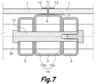
- FIG. 7 shows a section view of part of a fifth exemplary embodiment of a photovoltaic assembly for a portable solar energy system, wherein the auxiliary members 71 are in contact with each other by their wall perpendicular to the upper wall 9 of the support element 2.
- the auxiliary members 71 can also be attached between them, forming an H-shaped element.
- Both C-shaped auxiliary members 71 can be replaced in other embodiments by a single H-shaped element.
- Either the C-shaped auxiliary members 71, or the H-shaped element define two grooves 73 for the reception of the side edge of the corresponding photovoltaic laminate 1.
- the cutting plane of FIG. 7 is perpendicular to the internal major surface of the laminate 1 and cuts the interconnection pin 12 through its longitudinal axis.
- a face of the articulated members 4, 5 is substantially parallel to the internal major surface of the photovoltaic laminate 1.
- the upper face of the articulated member 4, 5, i.e., the face of the articulated member 4, 5 closer to the photovoltaic laminate 1 is substantially parallel to the internal major surface of the photovoltaic laminate 1.
- the distance between said face of the articulated member 4, 5 and the internal major surface of the photovoltaic laminate 1 may be less than 5 cm.
- said distance may be less than 3 cm. More preferably, said distance may be less than 2 cm. Even more preferably, said distance may be less than 1 cm.
- the support elements 2 of the exemplary embodiments shown in FIGS. 4 to 7 also have a closed cross-section.
- part of the foldable stiffening and/or supporting structure 3 could protrude from the support element 2, but still providing a compact arrangement of the photovoltaic assembly when in its folded position.
- the present invention provides a photovoltaic assembly for a portable energy system that can be easily transported and installed, thus reducing the transport and installation costs. Moreover, the photovoltaic assembly of the present invention can also be easily uninstalled, placed in its folded position, and transported to another location where it may be needed.
Landscapes
- Engineering & Computer Science (AREA)
- Life Sciences & Earth Sciences (AREA)
- Sustainable Development (AREA)
- Physics & Mathematics (AREA)
- Sustainable Energy (AREA)
- Thermal Sciences (AREA)
- Chemical & Material Sciences (AREA)
- Combustion & Propulsion (AREA)
- Mechanical Engineering (AREA)
- General Engineering & Computer Science (AREA)
- Photovoltaic Devices (AREA)
Priority Applications (11)
| Application Number | Priority Date | Filing Date | Title |
|---|---|---|---|
| EP21196430.9A EP4148979A1 (fr) | 2021-09-13 | 2021-09-13 | Ensemble photovoltaïque pliable pour un système d'énergie solaire portable |
| CN202280071049.9A CN118140406A (zh) | 2021-09-13 | 2022-09-13 | 用于便携式太阳能系统的可折叠光伏组件 |
| US18/691,601 US20250202415A1 (en) | 2021-09-13 | 2022-09-13 | Foldable photovoltaic assembly for a portable solar energy system |
| AU2022344535A AU2022344535A1 (en) | 2021-09-13 | 2022-09-13 | Foldable photovoltaic assembly for a portable solar energy system |
| PCT/EP2022/075384 WO2023037001A1 (fr) | 2021-09-13 | 2022-09-13 | Ensemble photovoltaïque pliable pour un système d'énergie solaire portable |
| EP22773533.9A EP4402793A1 (fr) | 2021-09-13 | 2022-09-13 | Ensemble photovoltaïque pliable pour un système d'énergie solaire portable |
| CA3231385A CA3231385A1 (fr) | 2021-09-13 | 2022-09-13 | Ensemble photovoltaique pliable pour un systeme d'energie solaire portable |
| MX2024003094A MX2024003094A (es) | 2021-09-13 | 2022-09-13 | Conjunto fotovoltaico plegable para un sistema de energia solar portatil. |
| CL2024000747A CL2024000747A1 (es) | 2021-09-13 | 2024-03-13 | Conjunto fotovoltaico plegable para sistema portátil de energía solar |
| ZA2024/02484A ZA202402484B (en) | 2021-09-13 | 2024-03-27 | Foldable photovoltaic assembly for a portable solar energy system |
| CONC2024/0004455A CO2024004455A2 (es) | 2021-09-13 | 2024-04-12 | Conjunto fotovoltaico plegable para sistema portátil de energía solar |
Applications Claiming Priority (1)
| Application Number | Priority Date | Filing Date | Title |
|---|---|---|---|
| EP21196430.9A EP4148979A1 (fr) | 2021-09-13 | 2021-09-13 | Ensemble photovoltaïque pliable pour un système d'énergie solaire portable |
Publications (1)
| Publication Number | Publication Date |
|---|---|
| EP4148979A1 true EP4148979A1 (fr) | 2023-03-15 |
Family
ID=77750079
Family Applications (2)
| Application Number | Title | Priority Date | Filing Date |
|---|---|---|---|
| EP21196430.9A Withdrawn EP4148979A1 (fr) | 2021-09-13 | 2021-09-13 | Ensemble photovoltaïque pliable pour un système d'énergie solaire portable |
| EP22773533.9A Pending EP4402793A1 (fr) | 2021-09-13 | 2022-09-13 | Ensemble photovoltaïque pliable pour un système d'énergie solaire portable |
Family Applications After (1)
| Application Number | Title | Priority Date | Filing Date |
|---|---|---|---|
| EP22773533.9A Pending EP4402793A1 (fr) | 2021-09-13 | 2022-09-13 | Ensemble photovoltaïque pliable pour un système d'énergie solaire portable |
Country Status (10)
| Country | Link |
|---|---|
| US (1) | US20250202415A1 (fr) |
| EP (2) | EP4148979A1 (fr) |
| CN (1) | CN118140406A (fr) |
| AU (1) | AU2022344535A1 (fr) |
| CA (1) | CA3231385A1 (fr) |
| CL (1) | CL2024000747A1 (fr) |
| CO (1) | CO2024004455A2 (fr) |
| MX (1) | MX2024003094A (fr) |
| WO (1) | WO2023037001A1 (fr) |
| ZA (1) | ZA202402484B (fr) |
Citations (4)
| Publication number | Priority date | Publication date | Assignee | Title |
|---|---|---|---|---|
| WO2010098806A1 (fr) | 2009-02-24 | 2010-09-02 | Sunpower Corporation | Ensembles photovoltaïques et procédés de transport |
| EP2398065A2 (fr) * | 2010-06-21 | 2011-12-21 | Hong Fu Jin Precision Industry (ShenZhen) Co. Ltd. | Assemblage de support pour panneaux photovoltaïques |
| CN212179262U (zh) * | 2020-03-13 | 2020-12-18 | 北京能高自动化技术股份有限公司 | 一种可折叠式光伏电池板支架 |
| CN212627781U (zh) * | 2020-08-06 | 2021-02-26 | 深圳市勤益和实业有限公司 | 一种用于安装光伏组件的便携式h型折叠支架 |
Family Cites Families (2)
| Publication number | Priority date | Publication date | Assignee | Title |
|---|---|---|---|---|
| GB2543581B (en) * | 2015-10-23 | 2020-07-08 | Cep Ip | Single axis solar tracking assembly and method of installing such single axis solar tracking assembly |
| CN210111914U (zh) * | 2019-05-30 | 2020-02-21 | 宁波宏升电子科技有限公司 | 一种使用方便的太阳能板支架及太阳能组件 |
-
2021
- 2021-09-13 EP EP21196430.9A patent/EP4148979A1/fr not_active Withdrawn
-
2022
- 2022-09-13 MX MX2024003094A patent/MX2024003094A/es unknown
- 2022-09-13 EP EP22773533.9A patent/EP4402793A1/fr active Pending
- 2022-09-13 WO PCT/EP2022/075384 patent/WO2023037001A1/fr not_active Ceased
- 2022-09-13 AU AU2022344535A patent/AU2022344535A1/en active Pending
- 2022-09-13 CA CA3231385A patent/CA3231385A1/fr active Pending
- 2022-09-13 CN CN202280071049.9A patent/CN118140406A/zh active Pending
- 2022-09-13 US US18/691,601 patent/US20250202415A1/en active Pending
-
2024
- 2024-03-13 CL CL2024000747A patent/CL2024000747A1/es unknown
- 2024-03-27 ZA ZA2024/02484A patent/ZA202402484B/en unknown
- 2024-04-12 CO CONC2024/0004455A patent/CO2024004455A2/es unknown
Patent Citations (4)
| Publication number | Priority date | Publication date | Assignee | Title |
|---|---|---|---|---|
| WO2010098806A1 (fr) | 2009-02-24 | 2010-09-02 | Sunpower Corporation | Ensembles photovoltaïques et procédés de transport |
| EP2398065A2 (fr) * | 2010-06-21 | 2011-12-21 | Hong Fu Jin Precision Industry (ShenZhen) Co. Ltd. | Assemblage de support pour panneaux photovoltaïques |
| CN212179262U (zh) * | 2020-03-13 | 2020-12-18 | 北京能高自动化技术股份有限公司 | 一种可折叠式光伏电池板支架 |
| CN212627781U (zh) * | 2020-08-06 | 2021-02-26 | 深圳市勤益和实业有限公司 | 一种用于安装光伏组件的便携式h型折叠支架 |
Also Published As
| Publication number | Publication date |
|---|---|
| EP4402793A1 (fr) | 2024-07-24 |
| US20250202415A1 (en) | 2025-06-19 |
| CO2024004455A2 (es) | 2024-04-29 |
| MX2024003094A (es) | 2024-05-06 |
| ZA202402484B (en) | 2025-07-30 |
| CL2024000747A1 (es) | 2024-09-06 |
| CA3231385A1 (fr) | 2023-03-16 |
| AU2022344535A1 (en) | 2024-05-02 |
| WO2023037001A1 (fr) | 2023-03-16 |
| CN118140406A (zh) | 2024-06-04 |
Similar Documents
| Publication | Publication Date | Title |
|---|---|---|
| US20240396493A1 (en) | Photovoltaic assembly for a portable solar energy system | |
| EP2569808B1 (fr) | Panneau de générateur photovoltaïque, procédé et système | |
| KR20140147701A (ko) | 태양광 발전 패널 설치대 및 전력 판매 분배 장치 | |
| JP6558632B2 (ja) | 太陽光発電装置 | |
| JP6026131B2 (ja) | 機能パネル支持架台 | |
| JP5213977B2 (ja) | 太陽電池モジュールの架台、その施工方法、及びそれを備えた太陽光発電システム | |
| WO2013092682A2 (fr) | Élément de construction solaire structurellement intégrée | |
| US20250202415A1 (en) | Foldable photovoltaic assembly for a portable solar energy system | |
| US20240396492A1 (en) | Assembly for a portable solar energy system | |
| WO2001003206A1 (fr) | Systeme d'encadrement pour panneaux en plaques planes | |
| PH12014501515B1 (en) | Panel supporting mount | |
| KR101716662B1 (ko) | 프레임리스 태양광 모듈 및 이를 지지하는 지지 구조물 | |
| JP5998741B2 (ja) | 太陽電池モジュール取付け構造 | |
| JP3185012U (ja) | 太陽光発電モジュール用架台 | |
| JP6029317B2 (ja) | 太陽電池モジュール | |
| JP5944129B2 (ja) | 切妻屋根建物 | |
| KR102851859B1 (ko) | 가로등 태양전지모듈 | |
| JP5932274B2 (ja) | 切妻屋根建物 | |
| WO2025016980A1 (fr) | Éléments de balcon et de balustrade | |
| JP2013243295A (ja) | 太陽電池サブアレイの設置方法および太陽電池サブアレイの搬送補助具 | |
| JP2013064275A (ja) | 屋根構造 |
Legal Events
| Date | Code | Title | Description |
|---|---|---|---|
| PUAI | Public reference made under article 153(3) epc to a published international application that has entered the european phase |
Free format text: ORIGINAL CODE: 0009012 |
|
| STAA | Information on the status of an ep patent application or granted ep patent |
Free format text: STATUS: THE APPLICATION HAS BEEN PUBLISHED |
|
| AK | Designated contracting states |
Kind code of ref document: A1 Designated state(s): AL AT BE BG CH CY CZ DE DK EE ES FI FR GB GR HR HU IE IS IT LI LT LU LV MC MK MT NL NO PL PT RO RS SE SI SK SM TR |
|
| STAA | Information on the status of an ep patent application or granted ep patent |
Free format text: STATUS: THE APPLICATION IS DEEMED TO BE WITHDRAWN |
|
| 18D | Application deemed to be withdrawn |
Effective date: 20230918 |