EP4149193A1 - Verfahren und vorrichtung zur ressourcenbestimmung - Google Patents
Verfahren und vorrichtung zur ressourcenbestimmung Download PDFInfo
- Publication number
- EP4149193A1 EP4149193A1 EP21821246.2A EP21821246A EP4149193A1 EP 4149193 A1 EP4149193 A1 EP 4149193A1 EP 21821246 A EP21821246 A EP 21821246A EP 4149193 A1 EP4149193 A1 EP 4149193A1
- Authority
- EP
- European Patent Office
- Prior art keywords
- time domain
- uplink
- domain resources
- indication information
- carrier
- Prior art date
- Legal status (The legal status is an assumption and is not a legal conclusion. Google has not performed a legal analysis and makes no representation as to the accuracy of the status listed.)
- Pending
Links
- 238000000034 method Methods 0.000 title claims abstract description 142
- 230000005540 biological transmission Effects 0.000 claims abstract description 219
- 230000011664 signaling Effects 0.000 claims abstract description 83
- 239000000969 carrier Substances 0.000 claims description 136
- 238000004891 communication Methods 0.000 claims description 41
- 238000004590 computer program Methods 0.000 claims description 17
- 230000008569 process Effects 0.000 description 37
- 238000010586 diagram Methods 0.000 description 25
- 230000006870 function Effects 0.000 description 18
- 238000010295 mobile communication Methods 0.000 description 12
- 238000005516 engineering process Methods 0.000 description 10
- 238000012545 processing Methods 0.000 description 7
- 230000009977 dual effect Effects 0.000 description 6
- 238000013461 design Methods 0.000 description 5
- 230000003190 augmentative effect Effects 0.000 description 2
- 230000008878 coupling Effects 0.000 description 2
- 238000010168 coupling process Methods 0.000 description 2
- 238000005859 coupling reaction Methods 0.000 description 2
- 230000003993 interaction Effects 0.000 description 2
- 230000007774 longterm Effects 0.000 description 2
- 230000004048 modification Effects 0.000 description 2
- 238000012986 modification Methods 0.000 description 2
- 238000001228 spectrum Methods 0.000 description 2
- 238000012546 transfer Methods 0.000 description 2
- 101100367123 Caenorhabditis elegans sul-1 gene Proteins 0.000 description 1
- 238000004422 calculation algorithm Methods 0.000 description 1
- 238000004364 calculation method Methods 0.000 description 1
- 238000011161 development Methods 0.000 description 1
- 230000000694 effects Effects 0.000 description 1
- 230000006872 improvement Effects 0.000 description 1
- 230000003287 optical effect Effects 0.000 description 1
- 230000008054 signal transmission Effects 0.000 description 1
- 230000000153 supplemental effect Effects 0.000 description 1
- 208000037918 transfusion-transmitted disease Diseases 0.000 description 1
Images



Classifications
-
- H—ELECTRICITY
- H04—ELECTRIC COMMUNICATION TECHNIQUE
- H04W—WIRELESS COMMUNICATION NETWORKS
- H04W72/00—Local resource management
- H04W72/04—Wireless resource allocation
- H04W72/044—Wireless resource allocation based on the type of the allocated resource
- H04W72/0446—Resources in time domain, e.g. slots or frames
-
- H—ELECTRICITY
- H04—ELECTRIC COMMUNICATION TECHNIQUE
- H04L—TRANSMISSION OF DIGITAL INFORMATION, e.g. TELEGRAPHIC COMMUNICATION
- H04L5/00—Arrangements affording multiple use of the transmission path
- H04L5/0001—Arrangements for dividing the transmission path
- H04L5/0014—Three-dimensional division
- H04L5/0023—Time-frequency-space
-
- H—ELECTRICITY
- H04—ELECTRIC COMMUNICATION TECHNIQUE
- H04L—TRANSMISSION OF DIGITAL INFORMATION, e.g. TELEGRAPHIC COMMUNICATION
- H04L5/00—Arrangements affording multiple use of the transmission path
- H04L5/003—Arrangements for allocating sub-channels of the transmission path
- H04L5/0053—Allocation of signalling, i.e. of overhead other than pilot signals
-
- H—ELECTRICITY
- H04—ELECTRIC COMMUNICATION TECHNIQUE
- H04L—TRANSMISSION OF DIGITAL INFORMATION, e.g. TELEGRAPHIC COMMUNICATION
- H04L5/00—Arrangements affording multiple use of the transmission path
- H04L5/14—Two-way operation using the same type of signal, i.e. duplex
- H04L5/1469—Two-way operation using the same type of signal, i.e. duplex using time-sharing
-
- H—ELECTRICITY
- H04—ELECTRIC COMMUNICATION TECHNIQUE
- H04W—WIRELESS COMMUNICATION NETWORKS
- H04W72/00—Local resource management
- H04W72/20—Control channels or signalling for resource management
- H04W72/23—Control channels or signalling for resource management in the downlink direction of a wireless link, i.e. towards a terminal
Definitions
- This application relates to the communication field, and more specifically, to a resource determining method and an apparatus in the communication field.
- a conventional cell includes one downlink carrier and one uplink carrier.
- Abase station sends a downlink signal to a terminal by using the downlink carrier, and the terminal sends an uplink signal to the base station by using the uplink carrier.
- TDD time division duplex
- FDD frequency division duplex
- the uplink carrier and the downlink carrier are at two separate frequencies, and there is a frequency spacing between the two frequencies.
- TDD is time division duplex.
- uplink and downlink multiplexing is performed in a same frequency band based on different time domain resources.
- FDD is frequency division duplex.
- uplink and downlink multiplexing is performed in different frequency bands.
- a frequency band used at an initial stage of deployment of the fifth generation (the fifth generation, 5G) mobile communication system is higher than a frequency band of the 4th generation (4th generation, 4G) mobile communication system.
- a 3.5 Gigahertz (Giga Hertz, GHz) band is used in 5G deployment.
- An electromagnetic wave with a higher frequency is featured by greater attenuation, and a transmit power of a terminal is lower than that of a base station. Therefore, a terminal at a cell edge can receive a downlink signal from the base station, but the base station cannot receive an uplink signal from the terminal.
- an uplink coverage area is smaller than a downlink coverage area.
- one or more additional uplink carriers at lower frequencies may be used in addition to an original uplink carrier of the cell, to send an uplink signal.
- the uplink carrier with a lower frequency may be referred to as a "supplementary uplink (supplemental uplink, SUL) band", an "SUL carrier”, or an "SUL resource”.
- SUL Supplemental uplink
- a time domain resource of an SUL carrier may be configured, so that SUL transmission is not affected by a service, for example, downlink transmission of the SUL carrier. This improves transmission reliability and an uplink transmission capacity.
- a resource determining method including: sending first indication information to a terminal device, where the first indication information indicates M time domain resources of a first uplink carrier, the first uplink carrier supports supplementary uplink SUL transmission, the M time domain resources are time domain resources that are in N time domain resources included in the first uplink carrier and that are used for SUL transmission, the N time domain resources include an uplink resource and/or a flexible time domain resource, the time domain resource includes a slot and/or a symbol, and M ⁇ N; and receiving a first uplink signal and/or an uplink channel by using the M time domain resources of the first uplink carrier.
- a dedicated SUL carrier is set in the conventional technology, and all uplink resources of the SUL carrier are used for uplink transmission.
- all or some time domain resources of the SUL carrier may be configured to send an uplink signal/uplink channel.
- all time domain resources of the SUL carrier are configured for uplink transmission. Compared with a case in which all time domain resources of the SUL carrier are used for uplink transmission at any time, this configuration manner is more flexible, and resource utilization is higher.
- time domain resources available to one or more SUL carriers may be configured.
- some time domain resources of the SUL carrier may support some downlink transmission.
- the available time domain resource used for uplink transmission is configured for the SUL carrier, so that SUL transmission is not affected by a service, for example, downlink transmission of the SUL carrier. This improves transmission reliability and further improves the uplink transmission capacity.
- some time domain resources of the one or more SUL carriers may be configured as dynamic or semi-static time domain resources for another service to use, so that resource utilization can be improved.
- the first uplink carrier may also be referred to as an "SUL carrier", and the system may include one or more first uplink carriers, in other words, include one or more SUL carriers.
- one SUL carrier is used as an example to describe a method for configuring an available resource for the SUL carrier.
- a quantity of SUL carriers (first uplink carriers) is not limited in this embodiment of this application.
- a base station may provide carriers for a plurality of terminal devices.
- the base station may provide an NR carrier for a first terminal device, used for uplink transmission and downlink transmission (NUL and NDL) of the terminal device.
- the base station may further provide an LTE carrier for a second terminal device, used for uplink transmission and downlink transmission (NUL and NDL) of the second terminal device.
- a frequency channel number of a band in which the NR carrier of the first terminal device is located may be higher than a frequency channel number of a band in which the LTE carrier of the second terminal device is located.
- the SUL carrier of the first terminal device may multiplex an LTE carrier of a lower frequency band of the second terminal device.
- both the first terminal device and the second terminal device may be terminal devices operating in NR, and the base station provides an NR carrier for each of the first terminal device and the second terminal device.
- a frequency band range of a frequency band in which the NR carrier of the first terminal device is located may be different from a frequency band range of a frequency band in which the NR carrier of the second terminal device is located.
- the SUL carrier of the first terminal device may multiplex an NR carrier of a lower frequency band of the second terminal device, or the SUL carrier of the second terminal device may multiplex an NR carrier of a lower frequency band of the first terminal device. It should be understood that an available scenario is not limited in this embodiment of this application.
- the band in which the SUL carrier is located may multiplex an LTE TDD band or a low-frequency FDD band for NR deployment.
- the base station may configure an available SUL carrier for the terminal device, predefine an associated SUL carrier for an NDL/NUL band of the terminal device, or the like. The manner is described in detail in another related patent application, and details are not described in this embodiment of this application.
- the first uplink carrier that supports supplementary uplink SUL transmission may include the N time domain resources, and the time domain resource may be specifically a "slot (time slot)" and/or a "time domain symbol (symbol)" described above.
- the N time domain resources of the first uplink carrier may include one or more of a time domain resource configured for uplink transmission (marked as "U"), a flexible time domain resource (flexible, marked as “F”), and a disabled time domain resource (marked as "D").
- U time domain resource configured for uplink transmission
- F flexible time domain resource
- D disabled time domain resource
- slots and/or symbols used for sending an uplink signal and/or an uplink channel on one or more SUL carriers may be configured, or a quantity of slots or symbols used for sending the first uplink signal and/or the uplink channel on the SUL carrier may be configured. This is not limited in this embodiment of this application.
- the base station may notify the terminal device of only information about the M time domain resources by using the first indication information, for example, information such as locations and a quantity of the M time domain resources.
- the terminal device may determine, by using the information about the locations and the quantity of the M time domain resources that are indicated by the first indication information, a time domain resource used for sending the first uplink signal and/or the uplink channel.
- the first indication information further indicates K flexible time domain resources
- the flexible time domain resource is used for SUL transmission or downlink transmission, and K ⁇ N.
- the receiving a first uplink signal and/or an uplink channel by using the M time domain resources of the first uplink carrier includes: receiving the first uplink signal and/or the uplink channel by using the M time domain resources and the K flexible time domain resources of the first uplink carrier.
- the first indication information is carried in a system information block SIB; or the first indication information is carried in downlink control information DCI; or the first indication information is carried in radio resource control RRC dedicated signaling.
- the base station may send the first indication information to the terminal device in different manners.
- the first indication information may be carried in different messages.
- a band in which the first uplink carrier is located further includes another resource used for downlink transmission, and the band in which the first uplink carrier is located is a TDD band.
- the band in which the first uplink carrier is located is a TDD band
- the band in which the first uplink carrier is located further includes another resource used for downlink transmission.
- the one or more SUL carriers in this embodiment of this application multiplex an existing LTE TDD band or a low-frequency FDD band deployed for NR, and the one or more SUL carriers are different from the dedicated SUL carrier configured in the conventional technology.
- any resource in the dedicated SUL carrier configured in the conventional technology may be used for uplink transmission, that is, sending a PUCCH/PUSCH.
- a slot and/or a symbol used by the first uplink carrier are/is configured as a subset of uplink slots and/or symbols and flexible slots and/or symbols to which the band in which the first uplink carrier is located belongs; or a slot and/or a symbol used by the first uplink carrier are/is configured as a subset of uplink slots and/or symbols or flexible slots and/or symbols to which the band in which the first uplink carrier is located belongs.
- the "subset" herein may include slots in which the SUL carrier is configured based on a same quantity of uplink slots and/or flexible slots, or symbols in which the SUL carrier is configured based on a same quantity of uplink symbols and/or flexible symbols, or slots in which the SUL carrier is configured based on a quantity less than a quantity of uplink slots and/or a quantity of flexible slots included in the band in which the SUL carrier is located, or symbols in which the SUL carrier is configured based on a quantity less than a quantity of uplink symbols and/or a quantity of flexible symbols included in the band in which the SUL carrier is located. This is not limited in this embodiment of this application.
- the method further includes: sending second indication information to the terminal device.
- the second indication information indicates L time domain resources that are in the K flexible time domain resources and that are used for SUL transmission, the L time domain resources include L0 uplink resources and L1 flexible time domain resources, and 0 ⁇ L ⁇ K.
- the receiving a first uplink signal and/or an uplink channel by using the M time domain resources of the first uplink carrier includes: receiving the first uplink signal and/or the uplink channel by using the M time domain resources and the L time domain resources of the first uplink carrier.
- the L time domain resources herein may include the L0 uplink resources and the L 1 flexible time domain resources.
- the L time domain resources herein may include L0 resources configured as "U” and L1 flexible time domain resources configured as "F".
- the base station may further modify the K flexible time domain resources that have been configured for the one or more SUL carriers based on different scenarios and requirements, that is, modify a configuration of flexible time domain resources by using the second indication information provided in this embodiment of this application.
- the second indication information is carried in radio resource control RRC dedicated signaling; or the second indication information is carried in downlink control information DCI.
- the second indication information may be carried in the radio resource control RRC dedicated signaling.
- the configuration of flexible time domain resources of the SUL carrier is further modified by using the RRC dedicated signaling.
- the second indication information may be further carried in the downlink control information DCI or a MAC CE.
- the second indication information is sent to the terminal device by using the DCI or the MAC CE, to further modify the flexible time domain resource F configured in the first indication information.
- the method further includes: sending third indication information to the terminal device.
- the third indication information indicates S time domain resources that are in the L1 flexible time domain resources and that are used for uplink transmission, and 0 ⁇ S ⁇ L1.
- the receiving a first uplink signal and/or an uplink channel by using the M time domain resources of the first uplink carrier includes: receiving the first uplink signal and/or the uplink channel by using the M time domain resources, the L0 uplink resources, and the S time domain resources of the first uplink carrier.
- the S time domain resources herein may include S0 uplink resources and S1 flexible time domain resources.
- the S time domain resources herein may include S0 resources configured as "U” and S 1 flexible time domain resources configured as "F".
- the base station may further modify the L1 configured flexible time domain resources of the one or more SUL carriers based on different scenarios and requirements, that is, modify the configuration of flexible time domain resource by using the third indication information provided in this embodiment of this application.
- the base station first sends the first indication information to the terminal device, configures the time domain resources of the one or more SUL carriers, and then sends the second indication information to the terminal device.
- the base station may further modify the configured flexible time domain resources of the one or more SUL carriers by using the third indication information provided in this embodiment of this application.
- the third indication information is carried in downlink control information DCI, and the DCI indicates one or more first uplink carriers used for SUL transmission.
- a specified slot and/or symbol on the SUL carrier may further be configured as a time domain resource in which the first uplink signal/channel may be sent.
- the DCI or the MAC CE may include the third indication information, to re-indicate a configuration status of the flexible time domain resources of the SUL carrier in a time period.
- n first uplink carriers are indicated by downlink control information DCI
- the DCI specifically indicates a set of slot format combinations
- the set of slot format combinations is used to configure the n first uplink carriers
- each slot format combination in the set of slot format combinations includes m single slot format indexes
- the single slot format index includes at least one of the following:
- the single slot format index is the same as a single slot format index configured for the TDD band in which the first uplink carrier is located; or a predefined first slot format, indicating the time domain resource used for SUL transmission; or a predefined second slot format, indicating the time domain resource used for SUL transmission and the flexible time domain resource.
- the first indication information when the first indication information is carried in the SIB or the RRC dedicated signaling, the first indication information further includes at least one configuration pattern and a reference subcarrier spacing SCS that indicates the first uplink carrier, and each configuration pattern includes a configuration cycle of a time domain resource of the first uplink carrier, and one or more of a quantity of uplink slots and/or symbols in the cycle, a quantity of flexible slots and/or symbols in the cycle, and a quantity of disabled resource slots and/or symbols in the cycle.
- some time domain resources of the SUL carrier may support some downlink transmission.
- the available time domain resource used for uplink transmission is configured for the SUL carrier, so that SUL transmission is not affected by a service, for example, downlink transmission of the SUL carrier. This improves transmission reliability and further improves the uplink transmission capacity.
- some time domain resources of the one or more SUL carriers may be configured as dynamic or semi-static time domain resources for another service to use, so that resource utilization can be improved.
- a resource determining method including: receiving first indication information sent by a network device, where the first indication information indicates M time domain resources of a first uplink carrier, the first uplink carrier supports supplementary uplink SUL transmission, the M time domain resources are time domain resources that are in N time domain resources included in the first uplink carrier and that are used for SUL transmission, the N time domain resources include an uplink resource and/or a flexible time domain resource, the time domain resource includes a slot and/or a symbol, and M ⁇ N; and sending a first uplink signal and/or an uplink channel based on the first indication information by using the M time domain resources of the first uplink carrier.
- the first indication information further indicates K flexible time domain resources
- the flexible time domain resource is used for SUL transmission or downlink transmission, and K ⁇ N.
- the sending a first uplink signal and/or an uplink channel by using the M time domain resources of the first uplink carrier includes: sending the first uplink signal and/or the uplink channel by using the M time domain resources and the K flexible time domain resources of the first uplink carrier.
- the first indication information is carried in a system information block SIB; or the first indication information is carried in downlink control information DCI; or the first indication information is carried in radio resource control RRC dedicated signaling.
- a band in which the first uplink carrier is located further includes another resource used for downlink transmission, and the band in which the first uplink carrier is located is a TDD band.
- a slot and/or a symbol used by the first uplink carrier are/is configured as a subset of uplink slots and/or symbols and flexible slots and/or symbols to which the band in which the first uplink carrier is located belongs; or a slot and/or a symbol used by the first uplink carrier are/is configured as a subset of uplink slots and/or symbols or flexible slots and/or symbols to which the band in which the first uplink carrier is located belongs.
- the method further includes: receiving second indication information sent by the network device.
- the second indication information indicates L time domain resources that are in the K flexible time domain resources and that are used for SUL transmission, 0 ⁇ L ⁇ K, and the L time domain resources include L0 uplink resources and L1 flexible time domain resources.
- the sending a first uplink signal and/or an uplink channel by using the M time domain resources of the first uplink carrier includes: sending the first uplink signal and/or the uplink channel by using the M time domain resources and the L time domain resources of the first uplink carrier.
- the second indication information is carried in radio resource control RRC dedicated signaling; or the second indication information is carried in downlink control information DCI.
- the method further includes: receiving third indication information sent by the network device.
- the third indication information indicates S time domain resources that are in the L1 time domain resources and that are used for uplink transmission, and 0 ⁇ S ⁇ L1.
- the S time domain resources include S0 uplink resources and S 1 flexible time domain resources.
- the sending a first uplink signal and/or an uplink channel by using the M time domain resources of the first uplink carrier includes: sending the first uplink signal and/or the uplink channel by using the M time domain resources, the L0 uplink resources, and the S time domain resources of the first uplink carrier.
- the third indication information is carried in downlink control information DCI, and the DCI indicates one or more first uplink carriers used for SUL transmission.
- n first uplink carriers are indicated by downlink control information DCI
- the DCI specifically indicates a set of slot format combinations
- the set of slot format combinations is used to configure the n first uplink carriers
- each slot format combination in the set of slot format combinations includes m single slot format indexes
- the single slot format index includes at least one of the following:
- the single slot format index is the same as a single slot format index configured for the TDD band in which the first uplink carrier is located, and a configuration of a downlink symbol in the single slot format is ignored; or a predefined first slot format, indicating the time domain resource used for SUL transmission; or a predefined second slot format, indicating the time domain resource used for SUL transmission and the flexible time domain resource.
- the first indication information when the first indication information is carried in the SIB or the RRC dedicated signaling, the first indication information further includes at least one configuration pattern and a reference subcarrier spacing SCS that indicates the first uplink carrier, and each configuration pattern includes a configuration cycle of a time domain resource of the first uplink carrier, and one or more of a quantity of uplink slots and/or symbols in the cycle, a quantity of flexible slots and/or symbols in the cycle, and a quantity of disabled resource slots and/or symbols in the cycle.
- an apparatus including: a sending unit, configured to send first indication information to a terminal device, where the first indication information indicates M time domain resources of a first uplink carrier, the first uplink carrier supports supplementary uplink SUL transmission, the M time domain resources are time domain resources that are in N time domain resources included in the first uplink carrier and that are used for SUL transmission, the N time domain resources include an uplink resource and/or a flexible time domain resource, the time domain resource includes a slot and/or a symbol, and M ⁇ N; and a receiving unit, configured to receive a first uplink signal and/or an uplink channel by using the M time domain resources of the first uplink carrier.
- the first indication information when the N time domain resources include a flexible time domain resource, the first indication information further indicates K flexible time domain resources.
- the flexible time domain resource is used for SUL transmission or downlink transmission, and K ⁇ N.
- the receiving unit is further configured to receive the first uplink signal and/or the uplink channel by using the M time domain resources and the K flexible time domain resources of the first uplink carrier.
- the first indication information is carried in a system information block SIB; or the first indication information is carried in downlink control information DCI; or the first indication information is carried in radio resource control RRC dedicated signaling.
- a band in which the first uplink carrier is located further includes another resource used for downlink transmission, and the band in which the first uplink carrier is located is a TDD band.
- a slot and/or a symbol used by the first uplink carrier are/is configured as a subset of uplink slots and/or symbols and flexible slots and/or symbols to which the band in which the first uplink carrier is located belongs; or a slot and/or a symbol used by the first uplink carrier are/is configured as a subset of uplink slots and/or symbols or flexible slots and/or symbols to which the band in which the first uplink carrier is located belongs.
- the sending unit is further configured to send second indication information to the terminal device.
- the second indication information indicates L time domain resources that are in the K flexible time domain resources and that are used for SUL transmission, 0 ⁇ L ⁇ K, the L time domain resources include L0 uplink resources and L 1 flexible time domain resources, and 0 ⁇ L ⁇ K.
- That the receiving unit is further configured to receive a first uplink signal and/or an uplink channel by using the M time domain resources of the first uplink carrier includes: receiving the first uplink signal and/or the uplink channel by using the M time domain resources and the L time domain resources of the first uplink carrier.
- the second indication information is carried in radio resource control RRC dedicated signaling; or the second indication information is carried in downlink control information DCI.
- the sending unit is further configured to send third indication information to the terminal device.
- the third indication information indicates S time domain resources that are in the L 1 flexible time domain resources and that are used for uplink transmission, 0 ⁇ S ⁇ L1, and the S time domain resources include S0 uplink resources and S1 flexible time domain resources.
- the receiving unit is further configured to receive the first uplink signal and/or the uplink channel by using the M time domain resources, the L0 uplink resources, and the S time domain resources of the first uplink carrier.
- the third indication information is carried in downlink control information DCI, and the DCI indicates one or more first uplink carriers used for SUL transmission.
- n first uplink carriers are indicated by downlink control information DCI
- the DCI specifically indicates a set of slot format combinations
- the set of slot format combinations is used to configure the n first uplink carriers
- each slot format combination in the set of slot format combinations includes m single slot format indexes
- the single slot format index includes at least one of the following:
- the single slot format index is the same as a single slot format index configured for the TDD band in which the first uplink carrier is located; or a predefined first slot format, indicating the time domain resource used for SUL transmission; or a predefined second slot format, indicating the time domain resource used for SUL transmission and the flexible time domain resource.
- the first indication information when the first indication information is carried in the SIB or the RRC dedicated signaling, the first indication information further includes at least one configuration pattern and a reference subcarrier spacing SCS that indicates the first uplink carrier, and each configuration pattern includes a configuration cycle of a time domain resource of the first uplink carrier, and one or more of a quantity of uplink slots and/or symbols in the cycle, a quantity of flexible slots and/or symbols in the cycle, and a quantity of disabled resource slots and/or symbols in the cycle.
- an apparatus including: a receiving unit, configured to receive first indication information sent by a network device, where the first indication information indicates M time domain resources of a first uplink carrier, the first uplink carrier supports supplementary uplink SUL transmission, the M time domain resources are time domain resources that are in N time domain resources included in the first uplink carrier and that are used for SUL transmission, the N time domain resources include an uplink resource and/or a flexible time domain resource, the time domain resource includes a slot and/or a symbol, and M ⁇ N; and a sending unit, configured to send a first uplink signal and/or an uplink channel based on the first indication information by using the M time domain resources of the first uplink carrier.
- the first indication information when the N time domain resources include a flexible time domain resource, the first indication information further indicates K flexible time domain resources.
- the flexible time domain resource is used for SUL transmission or downlink transmission, and K ⁇ N.
- the sending unit is further configured to send the first uplink signal and/or the uplink channel by using the M time domain resources and the K flexible time domain resources of the first uplink carrier.
- the first indication information is carried in a system information block SIB; or the first indication information is carried in downlink control information DCI; or the first indication information is carried in radio resource control RRC dedicated signaling.
- a band in which the first uplink carrier is located further includes another resource used for downlink transmission, and the band in which the first uplink carrier is located is a TDD band.
- a slot and/or a symbol used by the first uplink carrier are/is configured as a subset of uplink slots and/or symbols and flexible slots and/or symbols to which the band in which the first uplink carrier is located belongs; or a slot and/or a symbol used by the first uplink carrier are/is configured as a subset of uplink slots and/or symbols or flexible slots and/or symbols to which the band in which the first uplink carrier is located belongs.
- the receiving unit is further configured to receive second indication information sent by the network device.
- the second indication information indicates L time domain resources that are in the K flexible time domain resources and that are used for SUL transmission, 0 ⁇ L ⁇ K, and the L time domain resources include L0 uplink resources and L 1 flexible time domain resources.
- the sending unit is further configured to send the first uplink signal and/or the uplink channel by using the M time domain resources and the L flexible time domain resources of the first uplink carrier.
- the second indication information is carried in radio resource control RRC dedicated signaling; or the second indication information is carried in downlink control information DCI.
- the receiving unit is further configured to receive third indication information sent by the network device.
- the third indication information indicates S time domain resources that are in the L1 flexible time domain resources and that are used for uplink transmission, 0 ⁇ S ⁇ L1, and the S time domain resources include S0 uplink resources and S 1 flexible time domain resources.
- the sending unit is further configured to send the first uplink signal and/or the uplink channel by using the M time domain resources, the L0 uplink resources, and the S time domain resources of the first uplink carrier.
- the third indication information is carried in downlink control information DCI, and the DCI indicates one or more first uplink carriers used for SUL transmission.
- n first uplink carriers are indicated by downlink control information DCI
- the DCI specifically indicates a set of slot format combinations
- the set of slot format combinations is used to configure the n first uplink carriers
- each slot format combination in the set of slot format combinations includes m single slot format indexes
- the single slot format index includes at least one of the following:
- the single slot format index is the same as a single slot format index configured for the TDD band in which the first uplink carrier is located, and a configuration of a downlink symbol in the single slot format is ignored; or a predefined first slot format, indicating the time domain resource used for SUL transmission; or a predefined second slot format, indicating the time domain resource used for SUL transmission and the flexible time domain resource.
- the first indication information when the first indication information is carried in the SIB or the RRC dedicated signaling, the first indication information further includes at least one configuration pattern and a reference subcarrier spacing SCS that indicates the first uplink carrier, and each configuration pattern includes a configuration cycle of a time domain resource of the first uplink carrier, and one or more of a quantity of uplink slots and/or symbols in the cycle, a quantity of flexible slots and/or symbols in the cycle, and a quantity of disabled resource slots and/or symbols in the cycle.
- a communication apparatus can implement functions of the network device (for example, the base station) in the method designs of the first aspect.
- the function may be implemented by hardware, or may be implemented by hardware by executing corresponding software.
- the hardware or the software includes one or more units corresponding to the foregoing functions.
- a communication apparatus has functions of implementing the terminal device in the method designs of the second aspect.
- the function may be implemented by hardware, or may be implemented by hardware by executing corresponding software.
- the hardware or the software includes one or more units corresponding to the foregoing functions.
- a network device includes a transceiver and a processor.
- the network device further includes a memory.
- the processor is configured to control the transceiver to send and receive a signal.
- the memory is configured to store a computer program.
- the processor is configured to invoke the computer program from the memory and run the computer program, so that the network device performs the method according to the second aspect or any possible implementation of the second aspect.
- a terminal device includes a transceiver and a processor.
- the terminal device further includes a memory.
- the processor is configured to control the transceiver to send and receive a signal.
- the memory is configured to store a computer program.
- the processor is configured to invoke the computer program from the memory and run the computer program, so that the terminal device performs the method according to the first aspect or any possible implementation of the first aspect.
- a communication system includes the network device in the third aspect and the terminal device in the fourth aspect.
- a communication apparatus may be the network device in the foregoing method designs, or may be a chip disposed in the network device.
- the communication apparatus includes a processor, coupled to a memory, and may be configured to execute instructions in the memory, to implement the method performed by the network device according to the first aspect or any possible implementation of the first aspect.
- the communication apparatus further includes the memory.
- the communication apparatus further includes a communication interface, and the processor is coupled to the communication interface.
- the communication interface may be a transceiver or an input/output interface.
- the communication interface may be an input/output interface.
- the transceiver may be a transceiver circuit.
- the input/output interface may be an input/output circuit.
- a communication apparatus may be the terminal device in the foregoing method designs, or may be a chip disposed in the terminal device.
- the communication apparatus includes a processor, coupled to a memory, and may be configured to execute instructions in the memory, to implement the method performed by the terminal device according to the second aspect or any possible implementation of the second aspect.
- the communication apparatus further includes the memory.
- the communication apparatus further includes a communication interface, and the processor is coupled to the communication interface.
- the communication interface may be a transceiver or an input/output interface.
- the communication interface may be an input/output interface.
- the transceiver may be a transceiver circuit.
- the input/output interface may be an input/output circuit.
- a computer program product includes computer program code, and when the computer program code is run on a computer, the computer is enabled to perform the methods in the foregoing aspects.
- a computer-readable storage medium stores program code, and when the computer program code is run on a computer, the computer is enabled to perform the methods according to the foregoing aspects.
- LTE long term evolution
- FDD frequency division duplex
- TDD time division duplex
- 5th generation 5th generation, 5G
- new radio new radio, NR
- FIG. 1 is a schematic architectural diagram of a mobile communication system applicable to an embodiment of this application.
- the wireless communication system may include at least one network device 101.
- the network device 101 communicates with one or more terminal devices (for example, a terminal device 102 and a terminal device 103 that are shown in FIG. 1 ).
- terminal devices for example, a terminal device 102 and a terminal device 103 that are shown in FIG. 1 .
- the network device sends a signal
- the network device is a transmit end
- the terminal device is a receive end.
- the terminal device sends a signal
- the terminal device is a transmit end
- the network device is a receive end.
- the terminal device may be located at a fixed position, or may be mobile.
- FIG. 1 is only a schematic diagram.
- the communication system may further include another network device, for example, may further include a wireless relay device and a wireless backhaul device, which are not shown in FIG. 1 .
- Types and quantities of network devices and terminal devices included in the mobile communication system are not limited in this embodiment of this application.
- a terminal device wirelessly accesses a network device in the mobile communication system.
- the radio access network device 101 may be a base station, an evolved NodeB (evolved NodeB, eNB), a home base station, an access point (access point, AP) in a wireless fidelity (wireless fidelity, Wi-Fi) system, a wireless relay node, a wireless backhaul node, a transmission point (transmission point, TP), a transmission reception point (transmission and reception point, TRP), a gNB in an NR system, or a component or a part of a device included in a base station, for example, a central unit (central unit, CU), a distributed unit (distributed unit, DU), or a baseband unit (baseband unit, BBU).
- a central unit central unit, CU
- distributed unit distributed unit
- DU baseband unit
- BBU baseband unit
- the network device is a radio access network device.
- the network device may be a network device itself, or may be a chip used in the network device to complete a wireless communication processing function.
- the terminal device in the mobile communication system 100 may also be referred to as a terminal, user equipment (user equipment, UE), a mobile station (mobile station, MS), a mobile terminal (mobile terminal, MT), or the like.
- the terminal device in embodiments of this application may be a mobile phone (mobile phone), a tablet computer (Pad), or a computer with a wireless transceiver function, or may be a wireless terminal used in scenarios such as a virtual reality (virtual reality, VR), an augmented reality (augmented reality, AR), industrial control (industrial control), self-driving (self-driving), remote medical (remote medical), a smart grid (smart grid), transportation safety (transportation safety), a smart city (smart city), and a smart home (smart home).
- the terminal device and a chip that can be used in the terminal device are collectively referred to as a terminal device. It should be understood that a specific technology used by and a specific device form of the terminal device are not limited in embodiments of this application.
- This embodiment of this application is applicable to downlink data transmission, or uplink data transmission, or device-to-device (device-to-device, D2D) data transmission.
- a data sending device is a network device
- a data receiving device is a terminal device. After receiving downlink data, the terminal device sends feedback information to the network device, to notify the network device whether the downlink data is correctly received by the terminal device.
- a data sending device is a terminal device
- a data receiving device is a network device. After receiving uplink data, the network device sends feedback information to the terminal device, to notify the terminal device whether the uplink data is correctly received by the network device.
- a data sending device is a terminal device
- a data receiving device is also a terminal device.
- a data transmission direction is not limited in this embodiment of this application.
- first, second, and third in embodiments of this application are merely used for distinguishing, and should not be construed as any limitation on this application.
- first uplink carrier in embodiments of this application represents a resource used for SUL transmission.
- sequence numbers of the processes do not mean execution sequences in various embodiments of this application.
- the execution sequences of the processes should be determined according to functions and internal logic of the processes, and should not be construed as any limitation on the implementation processes of embodiments of this application.
- presetting or “predefining” may be implemented by prestoring corresponding code or a table in a device (for example, including a terminal device and a network device), or in another manner that may indicate related information.
- a predefined slot format in embodiments of this application may be a slot configuration manner formulated in a standard. A specific implementation of the predefined slot format is not limited in this application.
- a slot may be understood as a part of serial self-multiplexing of slot information dedicated to a single channel.
- a slot can be considered as a channel.
- a symbol is also referred to as a time domain symbol, and may be an orthogonal frequency division multiplexing (orthogonal frequency division multiplexing, OFDM) symbol or a single carrier frequency division multiple access (single carrier frequency division multiple access, SC-FDMA) symbol.
- SC-FDMA is also referred to as orthogonal frequency division multiplexing with transform precoding (orthogonal frequency division multiplexing with transform precoding, OFDM with TP). This is not limited in embodiments of this application.
- duration of one frame is 10 ms, and each frame includes 10 subframes.
- a 30 kHz subcarrier is used as an example, each subframe includes 20 slots.
- Each subframe has two slots, and each slot is 0.5 ms and includes 14 OFDM symbols.
- Each slot in NR may have several resource blocks, and each resource block includes a plurality of subcarriers.
- duration of one frame is 10 ms, and includes 10 subframes whose duration is 1 ms.
- a 30 kHz subcarrier is used as an example, each subframe includes 20 slots.
- Each subframe has two slots, and each slot is 0.5 ms and includes 14 OFDM symbols. Therefore, it may be understood that the entire 10 ms frame is divided into several slots, which are used as data scheduling and transmission units, that is, transmission time intervals (transmission time intervals, TTIs). It should be understood that a frame structure is not limited in embodiments of this application.
- different carriers in NR may correspond to different reference subcarrier spacings (subcarrier spacings, SCSs).
- SCSs are 15 kHz, 30 kHz, and 60 kHz.
- one subframe includes different quantities of slots (slots).
- slots For a carrier whose SCS is 15 kHz, each subframe may include one slot.
- each subframe For a carrier whose SCS is 30 kHz, each subframe may include two slots.
- each subframe may include four slots.
- Each slot of carriers of different SCSs may include 14 symbols (symbols). Details are not described herein.
- a physical uplink channel is a channel used to carry uplink control information (uplink control information, UCI) and/or uplink data.
- the physical uplink channel may include a physical uplink control channel (physical uplink control channel, PUCCH) and a physical uplink shared channel (physical uplink share channel, PUSCH) that are defined in an LTE protocol or an NR protocol, and another uplink channel that has the foregoing functions and that is defined as a network evolves.
- Downlink control information is mainly used to send downlink scheduling assignment information, and has a plurality of different formats, including but not limited to DCI formats 0-0, 0-1, 1-0, 1-1, 2-0, 2-1, 2-2, 2-3, and the like. It should be understood that a format of the DCI is not limited in embodiments of this application.
- Supplementary uplink (supplementary uplink, SUL)
- a frequency band used at an initial stage of deployment of a 5G mobile communication system is higher than a frequency band of a 4th generation (4th generation, 4G) mobile communication system.
- An electromagnetic wave with a higher frequency has a greater attenuation, and a transmit power of a terminal is lower than that of a base station. Therefore, a terminal at a cell edge can receive a downlink signal from the base station, but the base station cannot receive an uplink signal from the terminal. As a result, an uplink coverage area is smaller than a downlink coverage area.
- FIG. 2 is a schematic diagram of cell deployment. Based on the background and the foregoing related descriptions, the base station is used as a network device, and a process of communication between a base station 101 and a terminal 102 is used as an example. As shown in FIG. 2 , an NR cell may include a normal downlink (Normal downlink, NDL) carrier and a normal uplink (Normal uplink, NUL) carrier.
- NDL normal downlink
- NUL normal uplink
- a downlink (downlink, DL) coverage area of the network device 101 is greater than an uplink (uplink, UL) coverage area of the network device 101, or a coverage area of a normal downlink (normal downlink, NDL) is greater than a coverage area of a normal uplink (normal uplink, NUL).
- a UL coverage area is less than a DL coverage area of a first frequency band.
- a supplementary uplink (supplementary uplink, SUL) carrier is introduced to NR.
- the carrier usually uses a low frequency, and therefore has smaller attenuation. This improves uplink coverage. Therefore, during actual deployment of an NR cell, one NR cell includes three carriers, for example, one downlink NDL carrier of a 3.5 gigahertz (Giga Hertz, GHz) frequency band, one NUL carrier of a 3.5 GHz frequency band, and one SUL carrier of a 1.8 GHz frequency band.
- An uplink service of the terminal device may be transmitted on the NUL and the SUL.
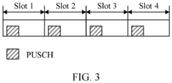
- FIG. 3 is a schematic diagram of sending a physical uplink shared channel. As shown in FIG. 3 , a repeatedly sent PUCCH/PUSCH may use a same time domain resource and/or a same frequency domain resource in each slot. Details are not described herein.
- an SUL frequency band configured for one cell is used only for uplink transmission.
- repeated transmission of the PUCCH/PUSCH is supported in the SUL frequency band.
- the SUL frequency band corresponds to an uplink symbol.
- a terminal considers that uplink transmission can be performed in any slot and symbol in the SUL frequency band.
- some resources in the SUL frequency band may be dynamically or semi-statically configured for another service, and may even support some downlink transmission.
- An embodiment of this application provides an SUL frequency band configuration method.
- a network device and a terminal device can determine a resource used for SUL transmission, to improve transmission reliability.
- a base station 101 is used as the network device, and a process of transmission between the base station 101 and a terminal device 102 shown in FIG. 2 is used as an example to specifically describe the SUL frequency band configuration method in this application.
- FIG. 4A and FIG. 4B are a schematic interaction diagram of a resource determining method 400 according to an embodiment of this application. It should be understood that this embodiment of this application may be applied to the scenario shown in FIG. 1 or FIG. 2 . Specifically, the method 400 may be applied to the terminal device or the base station in the scenario. An NDL carrier, an NUL carrier, and one or more SUL carriers are configured between the terminal device 102 and the base station 101. This is not limited in this embodiment of this application.
- the method 400 includes the following content.
- the base station 101 sends first indication information to the terminal device 102, where the first indication information indicates M time domain resources of a first uplink carrier.
- the first indication information may be determined by the base station 101 from N time domain resources included in the first uplink carrier.
- the base station 101 determines the M time domain resources in which the terminal device 102 performs supplementary uplink SUL transmission, and notifies the terminal device 102 of the M time domain resources by using the first indication information.
- the first uplink carrier supports supplementary uplink SUL transmission
- the first uplink carrier includes the N time domain resources
- the N time domain resources include an uplink resource and/or a flexible time domain resource
- the time domain resource includes a slot and/or a symbol
- M ⁇ N M ⁇ N.
- a dedicated SUL carrier is set in the conventional technology, and all uplink resources of the SUL carrier are used for uplink transmission.
- all or some time domain resources of the SUL carrier may be configured to send an uplink signal/uplink channel.
- all time domain resources of the SUL carrier are configured for uplink transmission. Compared with a case in which all time domain resources of the SUL carrier are used for uplink transmission at any time, this configuration manner is more flexible, and resource utilization is higher.
- the terminal device 102 determines, from the N time domain resources included in the first uplink carrier based on the first indication information, the M time domain resources used for supplementary uplink SUL transmission.
- the base station 101 sends the first indication information to the terminal device 102 according to the plurality of methods described in S420, and the terminal device 102 may configure the M available time domain resources for the SUL carrier based on the first indication information.
- the terminal device 102 sends a first uplink signal and/or an uplink channel to the base station 101 by using the M time domain resources of the first uplink carrier.
- the base station 101 receives, by using the M time domain resources of the first uplink carrier, the first uplink signal and/or the uplink channel sent by the terminal device 102.
- the first uplink carrier may also be referred to as an "SUL carrier", and the system may include one or more first uplink carriers, in other words, include one or more SUL carriers.
- one SUL carrier is used as an example to describe a method for configuring an available resource for the SUL carrier.
- a quantity of SUL carriers (first uplink carriers) is not limited in this embodiment of this application.
- a band in which the first uplink carrier is located is a TDD band
- the band in which the first uplink carrier is located further includes another resource used for downlink transmission.
- the one or more SUL carriers in this embodiment of this application multiplex an existing LTE TDD band or a low-frequency FDD band deployed for NR, and the one or more SUL carriers are different from the dedicated SUL carrier configured in the conventional technology.
- any resource in the dedicated SUL carrier configured in the conventional technology may be used for uplink transmission, that is, sending a PUCCH/PUSCH.
- the base station 101 may provide carriers for a plurality of terminal devices.
- the base station 101 may provide an NR carrier for a first terminal device, used for uplink transmission and downlink transmission (NUL and NDL) of the terminal device.
- the base station 101 may further provide an LTE carrier for a second terminal device, used for uplink transmission and downlink transmission (NUL and NDL) of the second terminal device.
- a frequency channel number of a band in which the NR carrier of the first terminal device is located may be higher than a frequency channel number of a band in which the LTE carrier of the second terminal device is located.
- the SUL carrier of the first terminal device may multiplex an LTE carrier of a lower frequency band of the second terminal device.
- both the first terminal device and the second terminal device may be terminal devices operating in NR, and the base station 101 provides an NR carrier for each of the first terminal device and the second terminal device.
- a frequency band range of a frequency band in which the NR carrier of the first terminal device is located may be different from a frequency band range of a frequency band in which the NR carrier of the second terminal device is located.
- the SUL carrier of the first terminal device may multiplex an NR carrier of a lower frequency band of the second terminal device, or the SUL carrier of the second terminal device may multiplex an NR carrier of a lower frequency band of the first terminal device. It should be understood that an available scenario is not limited in this embodiment of this application.
- a band in which an SUL carrier is located may multiplex an LTE TDD band or a low-frequency FDD band for NR deployment.
- the base station 101 may configure an available SUL carrier for the terminal device 102, predefine an associated SUL carrier for an NDL/NUL band of the terminal device 102, or the like. The manner is described in detail in another related patent application, and details are not described in this embodiment of this application.
- the first uplink carrier that supports supplementary uplink SUL transmission may include the N time domain resources, and the time domain resource may be specifically a "slot (time slot)" and/or a "time domain symbol (symbol)" described above.
- the N time domain resources of the first uplink carrier may include one or more of a time domain resource configured for uplink transmission (marked as "U"), a flexible time domain resource (flexible, marked as “F”), and a disabled time domain resource (marked as "D").
- U time domain resource configured for uplink transmission
- F flexible time domain resource
- D disabled time domain resource
- slots and/or symbols used for sending an uplink signal and/or an uplink channel on one or more SUL carriers may be configured, or a quantity of slots or symbols used for sending the first uplink signal and/or the uplink channel on an SUL carrier may be configured. This is not limited in this embodiment of this application.
- the base station 101 may determine, from the N symbols, M symbols for the terminal device 102 to send the first uplink signal and/or the uplink channel. In this process, the base station 101 may determine locations of the M symbols and/or the quantity M of symbols, and notify the terminal device 102 of the locations of the M symbols and/or the quantity M of symbols.
- the base station 101 may notify the terminal device 102 of only information about the M time domain resources by using the first indication information, for example, information such as locations and a quantity of the M time domain resources.
- the terminal device 102 may determine, by using the information about the locations and the quantity of the M time domain resources that are indicated by the first indication information, a time domain resource used for sending the first uplink signal and/or the uplink channel.
- the M time domain resources are time domain resources configured as "U", that is, the first indication information is used to configure an uplink resource of the SUL carrier.
- the first indication information when the N time domain resources include a flexible time domain resource, the first indication information further indicates K flexible time domain resources.
- the flexible time domain resource is used for SUL transmission or downlink transmission, and K ⁇ N.
- a process of S430 may be specifically as follows: The terminal device 102 sends the first uplink signal and/or the uplink channel to the base station 101 by using the M time domain resources and the K flexible time domain resources of the first uplink carrier. Correspondingly, the base station 101 receives the first uplink signal and/or the uplink channel by using the M time domain resources and the K flexible time domain resources of the first uplink carrier.
- the flexible time domain resource may be further configured for uplink transmission or downlink transmission.
- a resource marked as "F” may be further configured as "U” or "D”.
- the base station 101 may further notify the terminal device 102 of information about the flexible time domain resource (marked as "F").
- the time domain resources configured as U and F are resources that can be used for SUL transmission.
- a slot and/or a symbol used by the first uplink carrier are/is configured as a subset of uplink slots and/or symbols and flexible slots and/or symbols to which the band in which the first uplink carrier is located belongs; or a slot and/or a symbol used by the first uplink carrier are/is configured as a subset of uplink slots and/or symbols or flexible slots and/or symbols to which the band in which the first uplink carrier is located belongs.
- the base station 101 notifies, by using the first indication information, the terminal device 102 that configuration of the time domain resource of the SUL carrier may be determined based on a subset of a configuration set of the uplink slots and/or flexible slots of the band in which the SUL carrier is located.
- the "subset" herein may include slots in which the SUL carrier is configured based on a same quantity of uplink slots and/or flexible slots, or symbols in which the SUL carrier is configured based on a same quantity of uplink symbols and/or flexible symbols, or slots in which the SUL carrier is configured based on a quantity less than a quantity of uplink slots and/or a quantity of flexible slots included in the band in which the SUL carrier is located, or symbols in which the SUL carrier is configured based on a quantity less than a quantity of uplink symbols and/or a quantity of flexible symbols included in the band in which the SUL carrier is located. This is not limited in this embodiment of this application.
- the base station 101 may send the first indication information to the terminal device 102 in different manners.
- the first indication information may be carried in different messages.
- the first indication information may be carried in a system information block (system information block, SIB), or the first indication information is carried in downlink control information DCI, or the first indication information is carried in radio resource control (radio resource control, RRC) dedicated signaling.
- SIB system information block
- DCI downlink control information
- RRC radio resource control
- the base station 101 may send the first indication information to the terminal device 102 by using a system information block SIB, and configure the M time domain resources for one or more first uplink carriers by using the first indication information.
- SIB system information block
- the SIB further indicates K flexible time domain resources.
- the terminal device 102 may send the first uplink signal and/or the uplink channel to the base station 101 by using the M time domain resources and the K flexible time domain resources of the first uplink carrier.
- the base station 101 receives the first uplink signal and/or the uplink channel by using the M time domain resources and the K flexible time domain resources of the first uplink carrier.
- the SIB may include a plurality of configuration parameters
- the configuration parameter may include a reference subcarrier spacing (sub carrier spacing, SCS) and at least one configuration pattern (pattern) of the first uplink carrier.
- the configuration pattern (pattern) may include a configuration cycle in the configuration pattern.
- the terminal device 102 may obtain the information about the M time domain resources, that is, available uplink resources, based on the at least one configuration pattern and the configuration cycle in the configuration pattern.
- the at least one configuration pattern may include a single configuration pattern, a dual configuration pattern, and the like.
- a configuration format of a cycle and a configuration format of a time domain resource in each pattern in the single configuration pattern are the same, and a configuration format of a cycle and a configuration format of a time domain resource in each pattern in the dual configuration pattern may be different.
- FIG. 5 is a schematic diagram of a time domain resource configuration in a single configuration pattern according to an embodiment of this application.
- U represents a slot and/or a symbol that are/is configured as an uplink resource
- F represents a slot and/or a symbol that are/is configured as a flexible time domain resource
- D represents a slot and/or a symbol that are/is configured as a disabled time domain resource.
- the disabled time domain resource may be a time domain resource configured for downlink transmission. This is not limited in this embodiment of this application.
- the first indication information may include a configuration parameter in at least one of the following cases.
- the base station 101 may select any possible manner to configure the first uplink carrier for the terminal device 102, so that the terminal device 102 can determine, based on the first indication information, slots and/or symbols of the M time domain resources used for SUL transmission.
- signaling overheads can be reduced because of less configuration information included in the first indication information. For example, compared with the configuration manner (8), less configuration parameter information is involved in the configuration manner (1). This reduces signaling overheads.
- the terminal device 102 may sequentially configure a time domain resource of "U” and a time domain resource of "F” in a back-to-front configuration order in one pattern, determine the time domain resource of "F” and the time domain resource of "U” as time domain resources available for SUL transmission, and determine a remaining time domain resource in the pattern as a disabled time domain resource.
- the terminal device 102 first configures X symbols as uplink resources, marks the X symbols as "U”, configures Y symbols as flexible time domain resources, marks the Y symbols as "F”, configures Z symbols as disabled time domain resources, marks the Z symbols as "D”, and determines the time domain resources of "F” and the time domain resources of "U” as time domain resources used for SUL transmission.
- configuration may be performed according to this implementation, or configuration is performed in a front-to-back manner in each pattern. This is not limited in this embodiment of this application.
- each pattern may be configured according to the single configuration pattern described above, and details are not described herein again.
- the SIB may include a common configuration parameter. In other words, only parameters different from the common configuration parameter are configured for the plurality of SUL carriers, to reduce signaling overheads.
- FIG. 6 is a schematic diagram of a time domain resource configuration in a dual configuration pattern according to an embodiment of this application.
- configuration parameters in two patterns are included, and the configuration parameters in the two patterns are different.
- quantities of symbols included in X, Y, and Z in a configuration pattern 1 are partially or completely different.
- the first indication information may indicate a configuration parameter of a time domain resource in one cycle in the configuration pattern 1, and may also indicate a configuration parameter of a time domain resource in one cycle in a configuration pattern 2.
- the configuration pattern 1 and the configuration pattern 2 are cyclically performed in sequence to complete a time domain resource configuration of the first uplink carrier. Details are not described herein.
- the base station 101 may semi-statically configure available time domain resources for one or more SUL carriers by using the SIB.
- the terminal device 102 determines, based on the configuration information (the first indication information) in the SIB, a time domain resource that is configured as U and/or F as a time domain resource used for uplink transmission, and determines another time domain resource as a disabled time domain resource.
- time domain resources available to one or more SUL carriers may be configured.
- some time domain resources of the SUL carrier may support some downlink transmission.
- an available time domain resource used for uplink transmission is configured for the SUL carrier, so that SUL transmission is not affected by a service, for example, downlink transmission of the SUL carrier. This improves transmission reliability and further improves an uplink transmission capacity.
- some time domain resources of the one or more SUL carriers may be configured as dynamic or semi-static time domain resources for another service to use, so that resource utilization can be improved.
- the method may further include the following steps.
- the base station 101 sends second indication information to the terminal device 102, where the second indication information indicates L time domain resources that are in the K flexible time domain resources and that are used for SUL transmission, the L time domain resources include L0 uplink resources and L1 flexible time domain resources, and 0 ⁇ L ⁇ K.
- the terminal device 102 determines, from the K flexible time domain resources based on the second indication information, the L time domain resources used for SUL transmission.
- the L time domain resources herein may include the L0 uplink resources and the L1 flexible time domain resources.
- the L time domain resources herein may include L0 resources configured as "U” and L1 flexible time domain resources configured as "F".
- the terminal device 102 sends the first uplink signal and/or the uplink channel to the base station 101 by using the M time domain resources and the L time domain resources.
- the base station 101 receives, by using the M time domain resources and the L time domain resources of the first uplink carrier, the first uplink signal and/or the uplink channel sent by the terminal device 102.
- the base station 101 may further modify the configured time domain resources of the one or more SUL carriers based on different scenarios and requirements, that is, modify a configuration of flexible time domain resources by using the second indication information provided in this embodiment of this application.
- S420-1 and S430-1 may be understood as a specific implementation form of S420 and S430.
- S420-1 and S430-1 may replace S420 and S430, to determine a time domain resource used to send the first uplink signal/channel. This is not limited in this embodiment of this application.
- S440, S420-1, and S430-1 are optional steps in this embodiment of this application, and therefore are shown in dashed boxes in the method 400 in FIG. 4A and FIG. 4B .
- a configuration cycle of the SUL carrier may be the same as a semi-static configuration cycle of the SIB described in Manner 1.
- a configuration parameter of the first RRC dedicated signaling may overwrite the original flexible time domain resource (F) configured by using the SIB in the Manner 1, and after configuration of the first RRC dedicated signaling is accepted, the SUL carrier changes in each cycle based on the configuration parameter of the first RRC dedicated signaling.
- the second indication information may be implemented in the following two manners.
- the second indication information may be carried in the first radio resource control RRC dedicated signaling.
- the configuration of flexible time domain resources of the SUL carrier may be further modified in any one of the following possible manners by using the first RRC dedicated signaling: for example,
- the first RRC dedicated signaling may be embodied in the following form:
- the second indication information is sent to the terminal device 102 by using the first RRC dedicated signaling, to further modify the original flexible time domain resource F configured in the SIB.
- the K flexible time domain resources are configured by using the first indication information, and the L flexible time domain resources of the K flexible time domain resources may be reconfigured, by using the second indication information, as uplink resources used for SUL transmission.
- the L time domain resources include the L0 uplink resources and the L1 flexible time domain resources, and 0 ⁇ L ⁇ K.
- the base station 101 first sends the first indication information to the terminal device 102 by using the SIB, to configure the time domain resources of the one or more SUL carriers, then sends the second indication information to the terminal device 102 by using the first RRC dedicated signaling, to modify the flexible time domain resources of the one or more SUL carriers, and may further modify the configured flexible time domain resources of the one or more SUL carriers by using third indication information provided in this embodiment of this application.
- this embodiment of this application may further include the following steps.
- the base station 101 sends the third indication information to the terminal device 102, where the third indication information indicates S time domain resources that are in the L1 flexible time domain resources and that are used for uplink transmission, and 0 ⁇ S ⁇ L1.
- the terminal device 102 determines, from the L1 flexible time domain resources based on the third indication information, the S time domain resources used for SUL transmission.
- the S time domain resources herein may include S0 uplink resources and S1 flexible time domain resources.
- the S time domain resources herein may include S0 resources configured as "U” and S 1 flexible time domain resources configured as "F".
- the base station 101 may further modify the configured L1 flexible time domain resources of the one or more SUL carriers based on different scenarios and requirements, that is, modify the configuration of flexible time domain resources by using the third indication information provided in this embodiment of this application.
- the terminal device 102 sends the first uplink signal and/or the uplink channel to the base station 101 by using the M time domain resources, the L0 uplink resources, and the S time domain resources.
- the base station 101 receives, by using the M time domain resources, the L0 uplink resources, and the S time domain resources of the first uplink carrier, the first uplink signal and/or the uplink channel sent by the terminal device 102.
- S420-2 and S430-2 may be understood as a specific implementation form of S420 and S430, or S420-2, S430-2, S420-1, and S430-1 may replace implementation processes of S420 and S430, to determine a time domain resource used to send the first uplink signal/channel. This is not limited in this embodiment of this application.
- S450, S420-2, and S430-2 are optional steps in this embodiment of this application, and therefore are shown in dashed boxes in the method 400 in FIG. 4A and FIG. 4B .
- the third indication information may be carried in downlink control information DCI or a media access control element (media access control element, MAC CE), and the DCI indicates one or more first uplink carriers used for SUL transmission.
- DCI downlink control information
- MAC CE media access control element
- a specified slot and/or symbol on the SUL carrier may further be configured as a time domain resource in which the first uplink signal/channel may be sent.
- the DCI or the MAC CE may include the third indication information, to re-indicate a configuration status of the flexible time domain resources of the SUL carrier in a time period.
- the SUL carrier is reconfigured according to a time domain resource configuration rule indicated by the third indication information within 10 ms since the terminal device 102 receives the third indication information, until new DCI or a new MAC CE is received.
- the time domain resource of the SUL carrier is configured according to an original configuration rule of the first indication information and/or the second indication information; or if no time domain resource of the SUL carrier is configured for the first indication information and/or the second indication information previously, all the time domain resources of the SUL carrier may be configured as uplink resources. Details about a DCI configuration rule are not described in subsequent embodiments.
- the one or more SUL carriers and an NUL in a same cell as the one or more SUL carriers include at least two different types of subcarrier spacings
- the n SUL carriers may be configured in different manners.
- n+1 uplink carriers of the terminal device include n SUL carriers and one NUL carrier.
- Reference subcarrier spacings SCSs of the n+1 uplink carriers are respectively denoted as K 1 , K 2 , ..., K n , and K n +1 , where K min is a minimum reference subcarrier spacing of the uplink carriers of the terminal device.
- Ratios between the reference subcarrier spacings of the uplink carriers and the minimum reference subcarrier spacing is denoted as K 1 / K min , K 2 / K min , ..., K n / K min , and K n +1 / K min .
- the DCI or the MAC CE may indicate the set of slot format combinations (SlotFormatCombination).
- time domain resources are configured for the n+1 uplink carriers of the terminal device by using the m preconfigured single slot format indexes included in each slot format combination in the set of slot format combinations that is indicated by the DCI or the MAC CE.
- FIG. 7 is a schematic diagram of still another time domain resource configuration according to an embodiment of this application.
- one NUL carrier and two SUL carriers of the terminal device are used as an example.
- a reference subcarrier spacing corresponding to one NUL carrier is 60 kHz, and reference subcarrier spacings corresponding to two SUL carriers are 30 kHz and 15 kHz respectively.
- a slot of an SUL carrier with the minimum reference subcarrier spacing is used as a unit cycle, and the unit cycle may correspond to four slot configurations of an NUL carrier and two slot configurations of an SUL 1.
- m may be obtained through calculation according to the foregoing formula (1).
- each slot format combination indicated in the DCI or the MAC CE includes seven preconfigured single slot format indexes, and time domain resources are configured for three uplink carriers of the terminal device in a unit cycle.
- the single slot format index may multiplex a single slot format configured for a TDD band in which the SUL carrier is located, and the terminal device may ignore configuration of a downlink symbol (D) in the single slot format.
- D downlink symbol
- the single slot format index is determined according to a preset rule; or a predefined first slot format, indicating the time domain resource used for SUL transmission; or a predefined second slot format, indicating the time domain resource used for SUL transmission and the flexible time domain resource.
- FIG. 8 is a schematic diagram of yet another time domain resource configuration according to an embodiment of this application.
- the single slot format index multiplexes a slot configuration table in an existing standard, or as shown in (b) in FIG. 8 , the single slot format index is a slot configuration table newly defined in a standard. This is not limited in this embodiment of this application.
- each slot format combination includes seven preconfigured single slot format indexes.
- a slot format combination ⁇ 10, 11, 1, 1, 1, 2, 101 indicates that a slot 1, a slot 2, a slot 3, and a slot 4 of the 60 kHz NUL in FIG. 7 are configured according to 10, 11, 1, and 1. That is, the slot 1 is configured according to 14 symbols of a table row number 10 defined in (a) in FIG. 8 , and similarly, the slot 3 and the slot 4 are configured according to 14 symbols of a table row number 1 defined in (b) in FIG. 8 . Details are not described herein.
- the second indication information may be further carried in downlink control information DCI or a MAC CE.
- the second indication information is sent to the terminal device 102 by using the DCI or the MAC CE, to further modify the original flexible time domain resource F configured in the SIB.
- the K flexible time domain resources are configured by using the first indication information
- the L flexible time domain resources of the K flexible time domain resources may be reconfigured, by using the second indication information, as uplink resources used for SUL transmission, where 0 ⁇ L ⁇ K.
- a process in which the base station 101 modifies the time domain resource of the SUL carrier again by using the third indication information may be not performed.
- processes of S450, S420-2, and S430-2 described above are not performed.
- a configuration parameter of the DCI or the MAC CE may overwrite the original flexible time domain resource (F) configured in Manner 1.
- the base station 101 may send the first indication information to the terminal device 102 by using second RRC dedicated signaling, and configure the M time domain resources for the one or more first uplink carriers by using the first indication information.
- the second RRC dedicated signaling further indicates K flexible time domain resources.
- the terminal device 102 may send the first uplink signal and/or the uplink channel to the base station 101 by using the M time domain resources and the K flexible time domain resources of the first uplink carrier.
- the base station 101 receives the first uplink signal and/or the uplink channel by using the M time domain resources and the K flexible time domain resources of the first uplink carrier.
- a specified slot and/or symbol on the SUL carrier may be configured as a time domain resource in which the first uplink signal/channel may be sent.
- the first indication information included in the second RRC dedicated signaling may be used to configure the SUL carrier in any one of the eight configuration manners described in Manner 1. Details are not described herein again. For details, refer to the specific descriptions in Manner 1.
- the base station 101 may alternatively configure the time domain resource of the SUL carrier for the terminal device 102 by using the second RRC dedicated signaling and selecting the eight possible manners described in Manner 1, so that the terminal device 102 can determine, based on the second RRC dedicated signaling, the M time domain resources or slots and/or symbols of the M+K time domain resources used for SUL transmission, to implement a configuration effect the same as that of the SIB in Manner 1.
- the second RRC dedicated signaling herein is different from the first RRC dedicated signaling in Manner 1, and the first RRC dedicated signaling is a possible implementation of the second indication information. Therefore, the first RRC dedicated signaling and the second RRC dedicated signaling are merely used to distinguish between RRC dedicated signaling for implementing different purposes in different scenarios. In a specific implementation process, a format, content, and the like of the RRC dedicated signaling are not limited.
- the second RRC dedicated signaling may include a common configuration parameter. In other words, only parameters different from the common configuration parameter are configured for the plurality of SUL carriers, to reduce signaling overheads.
- the base station 101 when the base station 101 sends the first indication information to the terminal device 102 by using the second RRC dedicated signaling described in Manner 2, and configures, by using the second RRC dedicated signaling, that the N time domain resources of the first uplink carrier include the K flexible time domain resources, after S410 to S420, processes of S440, S420-1, and S430-1 in FIG. 4A and FIG. 4B may be further included. Details are not described herein again.
- the base station 101 may further modify the configured flexible time domain resources of the one or more SUL carriers based on different scenarios and requirements, that is, modify the flexible time domain resources by using the second indication information provided in this embodiment of this application.
- the second indication information may be implemented in the following two manners.
- the second indication information may be carried in first radio resource control RRC dedicated signaling.
- RRC dedicated signaling For a specific process of further modifying original configuration of the SUL carrier by using the first RRC dedicated signaling, refer to the related descriptions in Implementation 1 of Manner 1. Details are not described herein again.
- the second indication information is sent to the terminal device 102 by using the first RRC dedicated signaling, to further modify an original flexible time domain resource F configured in the second RRC dedicated signaling.
- the K flexible time domain resources are configured by using the first indication information, and L flexible time domain resources in the K flexible time domain resources may be reconfigured, by using the second indication information, as uplink resources used for SUL transmission.
- the L time domain resources include L0 uplink resources and L1 flexible time domain resources, and 0 ⁇ L ⁇ K.
- the base station 101 first sends the first indication information to the terminal device 102 by using the second RRC dedicated signaling, and then sends the second indication information to the terminal device 102 by using the first RRC dedicated signaling.
- the base station 101 may further modify the configured flexible time domain resources of the one or more SUL carriers, that is, modify the L1 flexible time domain resources by using third indication information provided in this embodiment of this application.
- processes of S450, S420-2, and S430-2 in FIG. 4A and FIG. 4B may be further included. Details are not described herein again.
- the third indication information may be carried in DCI or a MAC CE, and the DCI indicates one or more first uplink carriers used for SUL transmission.
- the third indication information included in the DCI or the MAC CE refer to the related descriptions in Implementation 1 of Manner 1. Details are not described herein again.
- the second indication information may be further carried in DCI or a MAC CE.
- the second indication information is sent to the terminal device 102 by using the DCI or the MAC CE, to further modify an original flexible time domain resource F configured in the second RRC dedicated signaling.
- the K flexible time domain resources are configured by using the first indication information
- L time domain resources in the K flexible time domain resources may be reconfigured by using the second indication information as L0 uplink resources and L1 flexible time domain resources used for SUL transmission, where 0 ⁇ L ⁇ K.
- a process in which the base station 101 modifies the time domain resource of the SUL carrier again by using the third indication information may be not performed.
- processes of S450, S420-2, and S430-2 described above are not performed. Details are not described herein again.
- time domain resources available to the one or more SUL carriers may be configured.
- some time domain resources of the SUL carrier may support some downlink transmission.
- an available time domain resource used for uplink transmission is configured for the SUL carrier, so that SUL transmission is not affected by a service, for example, downlink transmission of the SUL carrier. This improves transmission reliability and further improves an uplink transmission capacity.
- some time domain resources of the one or more SUL carriers may be configured as dynamic or semi-static time domain resources for another service to use, so that resource utilization can be improved.
- the base station 101 may dynamically send the first indication information to the terminal device 102 by using DCI or a MAC CE, and configure the M time domain resources for the one or more first uplink carriers by using the first indication information.
- the DCI or the MAC CE further indicates K flexible time domain resources.
- the terminal device 102 may send the first uplink signal and/or the uplink channel to the base station 101 by using the M time domain resources and the K flexible time domain resources of the first uplink carrier.
- the base station 101 receives the first uplink signal and/or the uplink channel by using the M time domain resources and the K flexible time domain resources of the first uplink carrier.
- the first indication information is sent to the terminal device 102 by using the DCI or the MAC CE, to configure the time domain resource of the SUL carrier.
- the base station 101 may dynamically configure available time domain resources for one or more SUL carriers by using the DCI or the MAC CE.
- the terminal device 102 After receiving the DCI or the MAC CE, the terminal device 102 determines, based on the configuration information (the first indication information) in the DCI or the MAC CE, a time domain resource that is configured as U and/or F as a time domain resource used for uplink transmission, and determines another time domain resource as a disabled time domain resource.
- time domain resources available to the one or more SUL carriers may be configured.
- some time domain resources of the SUL carrier may support some downlink transmission.
- an available time domain resource used for uplink transmission is configured for the SUL carrier, so that SUL transmission is not affected by a service, for example, downlink transmission of the SUL carrier. This improves transmission reliability and further improves an uplink transmission capacity.
- some time domain resources of the one or more SUL carriers may be configured as dynamic or semi-static time domain resources for another service to use, so that resource utilization can be improved.
- the terminal device 102 uses the time domain resource of the SUL carrier according to the following rules.
- the slot and/or the symbol of F may be modified by using the SIB, the RRC dedicated signaling, and the DCI, and priorities of modifying the slot and/or the symbol of F by using the foregoing three types of signaling are as follows: the priority of the SIB ⁇ the priority of the RRC dedicated signaling ⁇ the priority of the DCI/MAC CE.
- the terminal device may perform SUL transmission, that is, send the first uplink signal/uplink channel to the base station, in time domain resources that are finally configured as F and U. Another time domain resource cannot be used for SUL transmission.
- the terminal device detects DCI related to uplink scheduling only in resources related to the time domain resources configured as F and U, to determine whether to send uplink signals/uplink channels such as a PUCCH, a PUSCH, a physical random access channel (physical random access channel, PRACH), and a sounding reference signal (sounding reference signal, SRS).
- uplink signals/uplink channels such as a PUCCH, a PUSCH, a physical random access channel (physical random access channel, PRACH), and a sounding reference signal (sounding reference signal, SRS).
- the terminal device may ignore configuration of a disabled time domain resource "D" in the table, and apply only configuration solutions of the flexible time domain resource (F) and the uplink resource (U).
- a method for determining a time domain resource for SUL transmission is agreed upon between the terminal device 102 and the base station 101 by using a related definition of a rule for using the time domain resource of the SUL carrier by the terminal device 102. This helps the base station and the terminal device reach a consensus on SUL transmission, to improve transmission reliability.
- the terminal device 102 may cancel use of some time domain resources according to specific rules. For example, when dynamically configuring the time domain resource of the SUL carrier as a non-uplink resource (D or F) by using the DCI or the MAC CE, the base station 101 may cancel sending of an uplink signal and/or an uplink channel in the time domain resource configured by using RRC dedicated signaling.
- the cancellation rules are as follows.
- the time domain resources available to the one or more SUL carriers may be configured.
- some time domain resources of the SUL carrier may support some downlink transmission.
- the available time domain resource used for uplink transmission is configured for the SUL carrier, so that SUL transmission is not affected by a service, for example, downlink transmission of the SUL carrier. This improves transmission reliability and further improves the uplink transmission capacity.
- some time domain resources of the one or more SUL carriers may be configured as dynamic or semi-static time domain resources for another service to use, so that resource utilization can be improved.
- the foregoing embodiment further defines a rule for configuring the time domain resource of the SUL carrier for the terminal device and a rule for using the time domain resource of the SUL carrier by the terminal device.
- the terminal device can perform SUL transmission in only the available uplink resource and cancel uplink transmission in the disabled resource according to the specific rules. This further ensures that SUL transmission is not affected by a service, for example, downlink transmission, and improves transmission reliability.
- FIG. 9 is a schematic block diagram of a resource determining apparatus 900 according to an embodiment of this application.
- the apparatus 900 may correspond to the base station described in the method 400, or may be a chip or a component applied to the base station.
- modules or units in the apparatus 900 are separately configured to perform actions or processing processes performed by the base station in the method 400.
- the communication apparatus 900 may include a sending unit 910 and a receiving unit 920.
- the sending unit 910 is configured to send first indication information to a terminal device.
- the first indication information indicates M time domain resources of a first uplink carrier, the first uplink carrier supports supplementary uplink SUL transmission, the M time domain resources are time domain resources that are in N time domain resources included in the first uplink carrier and that are used for SUL transmission, the N time domain resources include an uplink resource and/or a flexible time domain resource, the time domain resource includes a slot and/or a symbol, and M ⁇ N.
- the receiving unit 920 is configured to receive a first uplink signal and/or an uplink channel by using the M time domain resources of the first uplink carrier.
- the first indication information when the N time domain resources include a flexible resource, when the N time domain resources include a flexible time domain resource, the first indication information further indicates K flexible time domain resources.
- the flexible time domain resource is used for SUL transmission or downlink transmission, and K ⁇ N.
- the receiving unit 920 is further configured to receive the first uplink signal and/or the uplink channel by using the M time domain resources and the K flexible time domain resources of the first uplink carrier.
- the first indication information is carried in a system information block SIB; or the first indication information is carried in downlink control information DCI; or the first indication information is carried in radio resource control RRC dedicated signaling.
- a band in which the first uplink carrier is located further includes another resource for downlink transmission, and the band in which the first uplink carrier is located is a TDD band.
- a slot and/or a symbol used by the first uplink carrier are/is configured as a subset of uplink slots and/or symbols and flexible slots and/or symbols to which the band in which the first uplink carrier is located belongs; or a slot and/or a symbol used by the first uplink carrier are/is configured as a subset of uplink slots and/or symbols or flexible slots and/or symbols to which the band in which the first uplink carrier is located belongs.
- the sending unit 910 is further configured to send second indication information to the user equipment.
- the second indication information indicates L flexible resources that are in the K flexible resources and that are used for SUL transmission, and 0 ⁇ L ⁇ K.
- the L time domain resources include L0 uplink resources and L1 flexible time domain resources, and 0 ⁇ L ⁇ K.
- the receiving unit 920 is further configured to receive the first uplink signal and/or the uplink channel by using the M time domain resources and the L time domain resources of the first uplink carrier.
- the second indication information is carried in radio resource control message RRC dedicated signaling; or the second indication information is carried in downlink control information DCI.
- the sending unit 910 is further configured to send third indication information to user equipment.
- the third indication information indicates S time domain resources that are in the L 1 flexible time domain resources and that are used for uplink transmission, and 0 ⁇ S ⁇ L1.
- the receiving unit 920 is further configured to receive the first uplink signal and/or the uplink channel by using the M time domain resources, the L0 uplink resources, and the S time domain resources of the first uplink carrier.
- the third indication information is carried in downlink control information DCI, and the DCI indicates one or more first uplink carriers used for SUL transmission.
- n first uplink carriers are indicated by downlink control information DCI
- the DCI specifically indicates a set of slot format combinations
- the set of slot format combinations is used to configure the n first uplink carriers
- the single slot format index includes at least one of the following:
- the single slot format index is the same as a single slot format index configured for the TDD band in which the first uplink carrier is located; or a predefined first slot format, indicating the time domain resource used for SUL transmission; or a predefined second slot format, indicating the time domain resource used for SUL transmission and the flexible time domain resource.
- the first indication information when the first indication information is carried in the SIB or the RRC dedicated signaling, the first indication information further includes at least one configuration pattern and a reference subcarrier spacing SCS that indicates the first uplink carrier, and each configuration pattern includes a configuration cycle of a time domain resource of the first uplink carrier, and one or more of a quantity of uplink slots and/or symbols in the cycle, a quantity of flexible slots and/or symbols in the cycle, and a quantity of disabled resource slots and/or symbols in the cycle.
- each configuration pattern includes a configuration cycle of a time domain resource of the first uplink carrier, and one or more of a quantity of uplink slots and/or symbols in the cycle, a quantity of flexible slots and/or symbols in the cycle, and a quantity of disabled resource slots and/or symbols in the cycle.
- the sending unit 910 is configured to perform S410, S440, and S450 in the method 400
- the receiving unit 920 is configured to perform S430, S430-1, and S430-2 in the method 400.
- a specific process in which each unit performs the foregoing corresponding steps is described in detail in the method 400. For brevity, details are not described herein again.
- FIG. 10 is a schematic block diagram of a resource determining apparatus 1000 according to an embodiment of this application.
- the apparatus 1000 may correspond to (for example, may be applied to or may be) the terminal device described in the method 400.
- modules or units in the apparatus 1000 are separately configured to perform actions or processing processes performed by the terminal device in the method 400.
- the communication apparatus 1000 may include a receiving unit 1010 and a sending unit 1020.
- the receiving unit 1010 is configured to receive first indication information sent by a network device.
- the first indication information indicates M time domain resources of a first uplink carrier, the first uplink carrier supports supplementary uplink SUL transmission, the M time domain resources are time domain resources that are in N time domain resources included in the first uplink carrier and that are used for SUL transmission, the N time domain resources include an uplink resource and/or a flexible time domain resource, the time domain resource includes a slot and/or a symbol, and M ⁇ N.
- the sending unit 1020 is configured to send a first uplink signal and/or an uplink channel based on the first indication information by using the M time domain resources of the first uplink carrier.
- the first indication information when the N time domain resources include a flexible time domain resource, the first indication information further indicates K flexible time domain resources.
- the flexible time domain resource is used for SUL transmission or downlink transmission, and K ⁇ N.
- the sending unit 1020 is further configured to send the first uplink signal and/or the uplink channel by using the M time domain resources and the K flexible time domain resources of the first uplink carrier.
- the first indication information is carried in a system information block SIB; or the first indication information is carried in downlink control information DCI; or the first indication information is carried in radio resource control RRC dedicated signaling.
- a band in which the first uplink carrier is located further includes another resource for downlink transmission, and the band in which the first uplink carrier is located is a TDD band.
- a slot and/or a symbol used by the first uplink carrier are/is configured as a subset of uplink slots and/or symbols and flexible slots and/or symbols to which the band in which the first uplink carrier is located belongs; or a slot and/or a symbol used by the first uplink carrier are/is configured as a subset of uplink slots and/or symbols or flexible slots and/or symbols to which the band in which the first uplink carrier is located belongs.
- the receiving unit 1010 is further configured to receive second indication information sent by the network device.
- the second indication information indicates L time domain resources that are in the K flexible time domain resources and that are used for SUL transmission, 0 ⁇ L ⁇ K, and the L time domain resources include L0 uplink resources and L1 flexible time domain resources.
- the sending unit 1020 is further configured to send the first uplink signal and/or the uplink channel by using the M time domain resources and the L flexible time domain resources of the first uplink carrier.
- the second indication information is carried in radio resource control RRC dedicated signaling; or the second indication information is carried in downlink control information DCI.
- the receiving unit 1010 is further configured to receive third indication information sent by the network device.
- the third indication information indicates S time domain resources that are in the L1 flexible time domain resources and that are used for uplink transmission, and 0 ⁇ S ⁇ L1.
- the sending unit 1020 is further configured to send the first uplink signal and/or the uplink channel by using the M time domain resources, the L0 uplink resources, and the S time domain resources of the first uplink carrier.
- the third indication information is carried in downlink control information DCI, and the DCI indicates one or more first uplink carriers used for SUL transmission.
- n first uplink carriers are indicated by downlink control information DCI
- the DCI specifically indicates a set of slot format combinations
- the set of slot format combinations is used to configure the n first uplink carriers
- each slot format combination in the set of slot format combinations includes m single slot format indexes
- the single slot format index includes at least one of the following:
- the single slot format index is the same as a single slot format index configured for the TDD band in which the first uplink carrier is located, and a configuration of a downlink symbol in the single slot format is ignored; or a predefined first slot format, indicating the time domain resource used for SUL transmission; or a predefined second slot format, indicating the time domain resource used for SUL transmission and the flexible time domain resource.
- the first indication information when the first indication information is carried in the SIB or the RRC dedicated signaling, the first indication information further includes at least one configuration pattern and a reference subcarrier spacing SCS that indicates the first uplink carrier, and each configuration pattern includes a configuration cycle of a time domain resource of the first uplink carrier, and one or more of a quantity of uplink slots and/or symbols in the cycle, a quantity of flexible slots and/or symbols in the cycle, and a quantity of disabled resource slots and/or symbols in the cycle.
- the receiving unit 1010 is configured to perform S410, S440, and S450 in the method 400
- the sending unit 1020 is configured to perform S430, S430-1, and S430-2 in the method 400.
- a specific process in which each unit performs the foregoing corresponding steps is described in detail in the method 400. For brevity, details are not described herein again.
- FIG. 11 is a schematic diagram of a structure of a network device 1100 according to an embodiment of this application.
- the network device 1100 for example, a base station
- the network device 1100 includes a processor 1110 and a transceiver 1120.
- the network device 1100 further includes a memory 1130.
- the processor 1110, the transceiver 1120, and the memory 1130 communicate with each other through an internal connection channel to transfer a control signal and/or a data signal.
- the memory 1130 is configured to store a computer program.
- the processor 1110 is configured to invoke and run the computer program in the memory 1130, to control the transceiver 1120 to receive and send a signal.
- the processor 1110 and the memory 1130 may be integrated into one processing apparatus.
- the processor 1110 is configured to execute program code stored in the memory 1130 to implement the function of the base station in the method embodiments.
- the memory 1130 may alternatively be integrated into the processor 1110, or may be independent of the processor 1110.
- the transceiver 1120 may be implemented by using a transceiver circuit.
- the network device may further include an antenna 1140, configured to send, by using a radio signal, downlink data or downlink control signaling that is output by the transceiver 1120, or send, after receiving uplink data or uplink control signaling, the uplink data or the uplink control signaling to the transceiver 820 for further processing.
- an antenna 1140 configured to send, by using a radio signal, downlink data or downlink control signaling that is output by the transceiver 1120, or send, after receiving uplink data or uplink control signaling, the uplink data or the uplink control signaling to the transceiver 820 for further processing.
- the apparatus 1100 may correspond to the base station in the method 400 according to embodiments of this application, and the apparatus 1100 may alternatively be a chip or a component used in the base station.
- the modules in the apparatus 1100 implement corresponding procedures in the method 400 in FIG. 4A and FIG. 4B .
- the memory 1130 is configured to store program code, so that when the processor 1110 executes the program code, the transceiver 1120 is configured to perform the processes of S410, S440, and S450 and S410, S430, S430-1, and S430-2 in the method 400. Specific processes of performing the foregoing corresponding steps by the units are described in detail in the method 400. For brevity, details are not described herein again.
- FIG. 12 is a schematic diagram of a structure of a terminal device 1200 according to an embodiment of this application.
- the terminal device 1200 includes a processor 1210 and a transceiver 1220.
- the terminal device 1200 further includes a memory 1230.
- the processor 1210, the transceiver 1220, and the memory 1230 may communicate with each other through an internal connection path, to transfer a control signal and/or a data signal.
- the memory 1230 is configured to store a computer program.
- the processor 1210 is configured to invoke and run the computer program in the memory 1230, to control the transceiver 1220 to receive and send a signal.
- the processor 1210 and the memory 1230 may be integrated into one processing apparatus.
- the processor 1210 is configured to execute program code stored in the memory 1230 to implement the function of the terminal device in the method embodiments.
- the memory 1230 may alternatively be integrated into the processor 1210, or may be independent of the processor 1210.
- the transceiver 1220 may be implemented by using a transceiver circuit.
- the terminal device may further include an antenna 1240, configured to send, by using a radio signal, uplink data or uplink control signaling output by the transceiver 1220, or send, after receiving downlink data or downlink control signaling, the downlink data or the downlink control signaling to the transceiver 1220 for further processing.
- an antenna 1240 configured to send, by using a radio signal, uplink data or uplink control signaling output by the transceiver 1220, or send, after receiving downlink data or downlink control signaling, the downlink data or the downlink control signaling to the transceiver 1220 for further processing.
- the apparatus 1200 may correspond to the terminal device in the method 400 according to embodiments of this application, and the apparatus 1200 may alternatively be a chip or a component used in the terminal device.
- the modules in the apparatus 1200 implement corresponding procedures in the method 400 in FIG. 4A and FIG. 4B .
- the memory 1230 is configured to store program code, so that when executing the program code, the processor 1210 controls the processor 1210 to perform S420, 5420-1, and S420-2 in the method 400, and the transceiver 1220 is configured to perform the processes of S410, S430, S440, and S450 and S430, S430-1, and S430-2 in the method 400. Specific processes in which each unit performs the foregoing corresponding steps are described in detail in the method 400. For brevity, details are not described herein again.
- the disclosed system, apparatus, and method may be implemented in other manners.
- the described apparatus embodiments are only examples.
- the unit division is only logical function division and may be other division during actual implementation.
- a plurality of units or components may be combined.
- the displayed or discussed mutual couplings or communication connections may be indirect couplings or communication connections through some interfaces, apparatuses, or units.
- function units in the embodiments of this application may be integrated into one physical entity, or each of the units may be separately corresponding to one physical entity, or two or more units may be integrated into one physical entity.
- the functions When the functions are implemented in the form of a software functional unit and sold or used as an independent product, the functions may be stored in a computer-readable storage medium. Based on such an understanding, the technical solutions of this application essentially, or the part contributing to the conventional technology, or some of the technical solutions may be implemented in a form of a software product.
- the computer software product is stored in a storage medium, and includes several instructions for instructing a computer device (which may be a personal computer, a server, or a network device) to perform all or some of the steps of the methods described in the embodiments of this application.
- the foregoing storage medium includes any medium that can store program code, such as a USB flash drive, a removable hard disk, a read-only memory (read-only memory, ROM), a random access memory (random access memory, RAM), a magnetic disk, or an optical disc.
- program code such as a USB flash drive, a removable hard disk, a read-only memory (read-only memory, ROM), a random access memory (random access memory, RAM), a magnetic disk, or an optical disc.
Landscapes
- Engineering & Computer Science (AREA)
- Signal Processing (AREA)
- Computer Networks & Wireless Communication (AREA)
- Mobile Radio Communication Systems (AREA)
Applications Claiming Priority (3)
| Application Number | Priority Date | Filing Date | Title |
|---|---|---|---|
| CN202010525719 | 2020-06-10 | ||
| CN202010689436.1A CN113784440B (zh) | 2020-06-10 | 2020-07-15 | 确定资源的方法和装置 |
| PCT/CN2021/081243 WO2021248960A1 (zh) | 2020-06-10 | 2021-03-17 | 确定资源的方法和装置 |
Publications (2)
| Publication Number | Publication Date |
|---|---|
| EP4149193A1 true EP4149193A1 (de) | 2023-03-15 |
| EP4149193A4 EP4149193A4 (de) | 2023-10-25 |
Family
ID=78835152
Family Applications (1)
| Application Number | Title | Priority Date | Filing Date |
|---|---|---|---|
| EP21821246.2A Pending EP4149193A4 (de) | 2020-06-10 | 2021-03-17 | Verfahren und vorrichtung zur ressourcenbestimmung |
Country Status (4)
| Country | Link |
|---|---|
| US (1) | US12484031B2 (de) |
| EP (1) | EP4149193A4 (de) |
| CN (1) | CN113784440B (de) |
| WO (1) | WO2021248960A1 (de) |
Families Citing this family (3)
| Publication number | Priority date | Publication date | Assignee | Title |
|---|---|---|---|---|
| CN113784440B (zh) * | 2020-06-10 | 2025-07-08 | 华为技术有限公司 | 确定资源的方法和装置 |
| CN113784358B (zh) * | 2020-06-10 | 2025-05-09 | 华为技术有限公司 | 确定sul频带的方法和装置 |
| CN116582945A (zh) * | 2022-01-29 | 2023-08-11 | 荣耀终端有限公司 | 时域资源配置方法、装置和系统 |
Family Cites Families (19)
| Publication number | Priority date | Publication date | Assignee | Title |
|---|---|---|---|---|
| EP3668170B1 (de) * | 2017-08-10 | 2025-12-17 | Ntt Docomo, Inc. | Benutzerendgerät und funkkommunikationsverfahren |
| WO2019083317A1 (ko) * | 2017-10-26 | 2019-05-02 | 엘지전자 주식회사 | 무선 통신 시스템에서 그룹 공통 dci에 따라 동작하는 방법 및 장치 |
| CN109803332B (zh) * | 2017-11-16 | 2021-02-05 | 华为技术有限公司 | 通信的方法、通信装置和系统 |
| KR102456001B1 (ko) * | 2017-11-16 | 2022-10-19 | 삼성전자주식회사 | 무선 통신 시스템에서 상향링크 캐리어를 통해 데이터를 송수신하기 위한 방법 및 장치 |
| US10749637B2 (en) * | 2018-01-18 | 2020-08-18 | FG Innovation Company Limited | Methods and devices for aperiodic uplink transmission |
| US10834761B2 (en) * | 2018-02-17 | 2020-11-10 | Ofinno, Llc | Cell uplink selection control |
| US10778368B2 (en) * | 2018-04-06 | 2020-09-15 | Lg Electronics Inc. | Method for determining slot format of user equipment in wireless communication system and user equipment using the same |
| US10608805B2 (en) * | 2018-04-20 | 2020-03-31 | At&T Intellectual Property I, L.P. | Supplementary uplink with LTE coexistence adjacent to frequency division duplex spectrum for radio networks |
| WO2019241235A1 (en) * | 2018-06-11 | 2019-12-19 | Ofinno, Llc | Base station network sharing configuration |
| KR102751886B1 (ko) * | 2018-08-03 | 2025-01-09 | 삼성전자주식회사 | 무선 통신 시스템에서 데이터를 송수신하기 위한 방법 및 장치 |
| CN111726874B (zh) * | 2018-11-19 | 2024-07-16 | 华为技术有限公司 | 一种上行链路切换的方法、通信装置和通信系统 |
| CN111225410B (zh) * | 2018-11-24 | 2022-05-10 | 华为技术有限公司 | 一种确定上行链路的方法及装置 |
| CN110278610B (zh) * | 2019-05-28 | 2022-07-22 | 华为技术有限公司 | 一种资源配置方法及通信装置 |
| CN110337152B (zh) * | 2019-06-11 | 2022-09-23 | 华为技术有限公司 | 一种配置sul的方法及通信装置 |
| JP7335441B2 (ja) * | 2019-11-06 | 2023-08-29 | 鴻穎創新有限公司 | Slキャリアアグリゲーション拡張のための方法及び装置 |
| US11601940B2 (en) * | 2019-12-04 | 2023-03-07 | Qualcomm Incorporated | Methods to configure uplink cancellation indication for supplementary uplink carriers |
| CN113784440B (zh) * | 2020-06-10 | 2025-07-08 | 华为技术有限公司 | 确定资源的方法和装置 |
| CN113811003B (zh) * | 2020-06-15 | 2025-05-06 | 华为技术有限公司 | 载波配置方法及相关装置 |
| KR20230147106A (ko) * | 2021-02-25 | 2023-10-20 | 삼성전자주식회사 | 무선 통신 시스템에서 페이징 기회를 모니터링하는 방법 및 장치 |
-
2020
- 2020-07-15 CN CN202010689436.1A patent/CN113784440B/zh active Active
-
2021
- 2021-03-17 US US18/009,624 patent/US12484031B2/en active Active
- 2021-03-17 EP EP21821246.2A patent/EP4149193A4/de active Pending
- 2021-03-17 WO PCT/CN2021/081243 patent/WO2021248960A1/zh not_active Ceased
Also Published As
| Publication number | Publication date |
|---|---|
| US12484031B2 (en) | 2025-11-25 |
| CN113784440B (zh) | 2025-07-08 |
| WO2021248960A1 (zh) | 2021-12-16 |
| US20230217420A1 (en) | 2023-07-06 |
| EP4149193A4 (de) | 2023-10-25 |
| CN113784440A (zh) | 2021-12-10 |
Similar Documents
| Publication | Publication Date | Title |
|---|---|---|
| EP3824686B1 (de) | Verfahren und vorrichtung zur ressourcenzuweisung | |
| CN108768599B (zh) | 上行信号的发送、接收方法及装置、存储介质、电子设备 | |
| US20240114489A1 (en) | Cli measurement method and communication apparatus | |
| US10651999B2 (en) | Transmission method, device and system | |
| CN110741597A (zh) | 针对5g-nr的半静态和动态tdd配置 | |
| US12279282B2 (en) | Child distributed unit resource configuration information signaling in 5G-NR integrated access backhaul network | |
| US12402113B2 (en) | Method and apparatus for SUL communication using a first carrier and downlink communication using a second carrier | |
| WO2024061261A1 (zh) | 资源配置方法及装置、终端及网络侧设备 | |
| US12294554B2 (en) | PUCCH design for unlicensed band operation at MMWAVES | |
| CN115553010B (zh) | 用于无线通信的装置和设备以及非暂态存储器元件 | |
| US12484031B2 (en) | Resource determining method and apparatus for uplink transmission | |
| US20240313913A1 (en) | Method, device and computer readable medium for communication | |
| WO2022027308A1 (en) | Enhanced configured grants | |
| US20240365297A1 (en) | Transmission Determining Method and Apparatus, Device, and Medium | |
| EP4354997A1 (de) | Signalübertragungsverfahren und -vorrichtung | |
| CN117812737A (zh) | 通信方法及通信装置 | |
| CA3127845A1 (en) | Signal transmission method and apparatus | |
| WO2024208058A1 (zh) | 数据传输方法及装置 | |
| WO2024168735A1 (zh) | 无线传输方法、装置、设备及存储介质 | |
| EP3496352A1 (de) | Verfahren und vorrichtung zur einstellung von symbolen | |
| US12047218B2 (en) | Physical downlink control channel monitoring and rate matching for remaining minimum system information in new radio unlicensed | |
| US20250358799A1 (en) | Method and device for configuring time domain unit, and chip | |
| EP4304273A1 (de) | Verfahren und vorrichtung zur ressourcenzuordnung | |
| WO2025040021A1 (zh) | 多载波传输方法和装置 | |
| WO2017174125A1 (en) | Method, system and apparatus |
Legal Events
| Date | Code | Title | Description |
|---|---|---|---|
| STAA | Information on the status of an ep patent application or granted ep patent |
Free format text: STATUS: THE INTERNATIONAL PUBLICATION HAS BEEN MADE |
|
| PUAI | Public reference made under article 153(3) epc to a published international application that has entered the european phase |
Free format text: ORIGINAL CODE: 0009012 |
|
| STAA | Information on the status of an ep patent application or granted ep patent |
Free format text: STATUS: REQUEST FOR EXAMINATION WAS MADE |
|
| 17P | Request for examination filed |
Effective date: 20221206 |
|
| AK | Designated contracting states |
Kind code of ref document: A1 Designated state(s): AL AT BE BG CH CY CZ DE DK EE ES FI FR GB GR HR HU IE IS IT LI LT LU LV MC MK MT NL NO PL PT RO RS SE SI SK SM TR |
|
| DAV | Request for validation of the european patent (deleted) | ||
| DAX | Request for extension of the european patent (deleted) | ||
| REG | Reference to a national code |
Ref country code: DE Ref legal event code: R079 Free format text: PREVIOUS MAIN CLASS: H04W0072040000 Ipc: H04L0005000000 |
|
| A4 | Supplementary search report drawn up and despatched |
Effective date: 20230922 |
|
| RIC1 | Information provided on ipc code assigned before grant |
Ipc: H04W 72/0446 20230101ALI20230918BHEP Ipc: H04L 5/00 20060101AFI20230918BHEP |