EP4149375B1 - Gelenkige chirurgische ultraschallinstrumente und systeme - Google Patents
Gelenkige chirurgische ultraschallinstrumente und systeme Download PDFInfo
- Publication number
- EP4149375B1 EP4149375B1 EP21727693.0A EP21727693A EP4149375B1 EP 4149375 B1 EP4149375 B1 EP 4149375B1 EP 21727693 A EP21727693 A EP 21727693A EP 4149375 B1 EP4149375 B1 EP 4149375B1
- Authority
- EP
- European Patent Office
- Prior art keywords
- ultrasonic
- distal
- surgical instrument
- proximal
- instrument according
- Prior art date
- Legal status (The legal status is an assumption and is not a legal conclusion. Google has not performed a legal analysis and makes no representation as to the accuracy of the status listed.)
- Active
Links
Images


Classifications
-
- A—HUMAN NECESSITIES
- A61—MEDICAL OR VETERINARY SCIENCE; HYGIENE
- A61B—DIAGNOSIS; SURGERY; IDENTIFICATION
- A61B17/00—Surgical instruments, devices or methods
- A61B17/32—Surgical cutting instruments
- A61B17/320068—Surgical cutting instruments using mechanical vibrations, e.g. ultrasonic
- A61B17/320092—Surgical cutting instruments using mechanical vibrations, e.g. ultrasonic with additional movable means for clamping or cutting tissue, e.g. with a pivoting jaw
-
- A—HUMAN NECESSITIES
- A61—MEDICAL OR VETERINARY SCIENCE; HYGIENE
- A61B—DIAGNOSIS; SURGERY; IDENTIFICATION
- A61B17/00—Surgical instruments, devices or methods
- A61B17/22—Implements for squeezing-off ulcers or the like on inner organs of the body; Implements for scraping-out cavities of body organs, e.g. bones; for invasive removal or destruction of calculus using mechanical vibrations; for removing obstructions in blood vessels, not otherwise provided for
- A61B17/22004—Implements for squeezing-off ulcers or the like on inner organs of the body; Implements for scraping-out cavities of body organs, e.g. bones; for invasive removal or destruction of calculus using mechanical vibrations; for removing obstructions in blood vessels, not otherwise provided for using mechanical vibrations, e.g. ultrasonic shock waves
- A61B17/22012—Implements for squeezing-off ulcers or the like on inner organs of the body; Implements for scraping-out cavities of body organs, e.g. bones; for invasive removal or destruction of calculus using mechanical vibrations; for removing obstructions in blood vessels, not otherwise provided for using mechanical vibrations, e.g. ultrasonic shock waves in direct contact with, or very close to, the obstruction or concrement
- A61B17/2202—Implements for squeezing-off ulcers or the like on inner organs of the body; Implements for scraping-out cavities of body organs, e.g. bones; for invasive removal or destruction of calculus using mechanical vibrations; for removing obstructions in blood vessels, not otherwise provided for using mechanical vibrations, e.g. ultrasonic shock waves in direct contact with, or very close to, the obstruction or concrement the ultrasound transducer being inside patient's body at the distal end of the catheter
-
- A—HUMAN NECESSITIES
- A61—MEDICAL OR VETERINARY SCIENCE; HYGIENE
- A61B—DIAGNOSIS; SURGERY; IDENTIFICATION
- A61B17/00—Surgical instruments, devices or methods
- A61B17/32—Surgical cutting instruments
- A61B17/320068—Surgical cutting instruments using mechanical vibrations, e.g. ultrasonic
- A61B2017/320071—Surgical cutting instruments using mechanical vibrations, e.g. ultrasonic with articulating means for working tip
-
- A—HUMAN NECESSITIES
- A61—MEDICAL OR VETERINARY SCIENCE; HYGIENE
- A61B—DIAGNOSIS; SURGERY; IDENTIFICATION
- A61B17/00—Surgical instruments, devices or methods
- A61B17/32—Surgical cutting instruments
- A61B17/320068—Surgical cutting instruments using mechanical vibrations, e.g. ultrasonic
- A61B2017/320089—Surgical cutting instruments using mechanical vibrations, e.g. ultrasonic node location
-
- A—HUMAN NECESSITIES
- A61—MEDICAL OR VETERINARY SCIENCE; HYGIENE
- A61B—DIAGNOSIS; SURGERY; IDENTIFICATION
- A61B17/00—Surgical instruments, devices or methods
- A61B17/32—Surgical cutting instruments
- A61B17/320068—Surgical cutting instruments using mechanical vibrations, e.g. ultrasonic
- A61B17/320092—Surgical cutting instruments using mechanical vibrations, e.g. ultrasonic with additional movable means for clamping or cutting tissue, e.g. with a pivoting jaw
- A61B2017/320093—Surgical cutting instruments using mechanical vibrations, e.g. ultrasonic with additional movable means for clamping or cutting tissue, e.g. with a pivoting jaw additional movable means performing cutting operation
-
- A—HUMAN NECESSITIES
- A61—MEDICAL OR VETERINARY SCIENCE; HYGIENE
- A61B—DIAGNOSIS; SURGERY; IDENTIFICATION
- A61B17/00—Surgical instruments, devices or methods
- A61B17/32—Surgical cutting instruments
- A61B17/320068—Surgical cutting instruments using mechanical vibrations, e.g. ultrasonic
- A61B17/320092—Surgical cutting instruments using mechanical vibrations, e.g. ultrasonic with additional movable means for clamping or cutting tissue, e.g. with a pivoting jaw
- A61B2017/320094—Surgical cutting instruments using mechanical vibrations, e.g. ultrasonic with additional movable means for clamping or cutting tissue, e.g. with a pivoting jaw additional movable means performing clamping operation
-
- A—HUMAN NECESSITIES
- A61—MEDICAL OR VETERINARY SCIENCE; HYGIENE
- A61B—DIAGNOSIS; SURGERY; IDENTIFICATION
- A61B34/00—Computer-aided surgery; Manipulators or robots specially adapted for use in surgery
- A61B34/30—Surgical robots
- A61B2034/305—Details of wrist mechanisms at distal ends of robotic arms
Definitions
- the present disclosure relates to surgical instruments and systems and, more particularly, to articulating ultrasonic surgical instruments and systems.
- Ultrasonic surgical instruments and systems utilize ultrasonic energy, i.e., ultrasonic vibrations, to treat tissue. More specifically, a typical ultrasonic surgical instrument or system includes a transducer configured to produce mechanical vibration energy at ultrasonic frequencies that is transmitted along a waveguide to an ultrasonic end effector configured to treat, e.g., coagulate, cauterize, fuse, seal, cut, desiccate, or otherwise treat tissue.
- a typical ultrasonic surgical instrument or system includes a transducer configured to produce mechanical vibration energy at ultrasonic frequencies that is transmitted along a waveguide to an ultrasonic end effector configured to treat, e.g., coagulate, cauterize, fuse, seal, cut, desiccate, or otherwise treat tissue.
- US 2014/005702 A1 discloses an ultrasonic instrument with a distally positioned end effector and flexible ultrasonic transducer assembly which comprises a distal transducer portion and a proximal transducer portion coupled by a bendable intermediate portion.
- distal refers to the portion that is being described which is further from a user
- proximal refers to the portion that is being described which is closer to a user
- an ultrasonic surgical instrument including a housing, an elongated shaft extending distally from the housing, an end effector extending distally from the elongated shaft, and a transducer assembly disposed at least partially within the elongated shaft.
- the end effector includes a jaw and an ultrasonic blade.
- the jaw is configured to pivot relative to the ultrasonic blade from an open position to a clamping position for clamping tissue therebetween.
- the transducer assembly is disposed at least partially within the elongated shaft, is distally-spaced from the housing, and includes proximal and distal transducers interconnected by a connector.
- the ultrasonic blade is connected to the distal transducer such that ultrasonic energy produced by the proximal transducer is transmitted along the connector and the distal transducer to the ultrasonic blade and such that ultrasonic energy produced by the distal transducer is transmitted to the ultrasonic blade.
- the connector is a flexible connector configured to articulate in at least one direction.
- the elongated shaft includes an articulating portion and the flexible connector may extend through the articulating portion such that the proximal transducer is disposed proximally of the articulating portion and such that the distal transducer is disposed distally of the articulating portion.
- the flexible connector may be formed as a band of material.
- the elongated shaft defines an outer diameter of less than about 15mm, less than about 12 mm, less than about 10 mm, less than about 8 mm, less than about 5 mm, or less than about 3mm; in aspects, between about 5 mm and about 8 mm.
- each of the proximal and distal transducers may define an outer diameter of less than 15mm, less than about 12 mm, less than about 10 mm, less than about 8 mm, less than about 5 mm, or less than about 3mm; in aspects, between about 5 mm and about 8 mm.
- each of the proximal and distal transducers includes a proximal mass, a distal mass, a stack of piezoelectric elements held under pre-compression between the proximal and distal masses, and first and second electrodes electrically coupled to the stack of piezoelectric elements.
- the ultrasonic blade defines a cylindrical configuration.
- the jaw may be configured to rotate about the ultrasonic blade such that the jaw is capable of clamping tissue between the jaw and blade at any rotational orientation of the jaw relative to the blade.
- the first and second transducers are disposed around vibration node points.
- the housing is adapted to connect to a robotic arm of a robotic surgical system.
- the housing includes at least one manual control.
- the proximal and distal transducers are driven by independent electrical drive signals.
- both of the proximal and distal transducers may be activated while, in a second mode of operation, only one of the proximal or distal transducers may be activated.
- an ultrasonic horn connects the distal transducer with the ultrasonic blade.
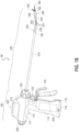
- FIGS. 1A and 1B an illustrative hand-held ultrasonic surgical instrument exemplifying the aspects and features of the present disclosure is shown generally identified by reference numeral 10.
- hand-held ultrasonic surgical instrument 10 is generally described. Aspects and features of hand-held ultrasonic surgical instrument 10 not germane to the understanding of the present disclosure are omitted to avoid obscuring the aspects and features of the present disclosure in unnecessary detail.
- Hand-held ultrasonic surgical instrument 10 generally includes a handle assembly 100 and an elongated assembly 200 extending distally from handle assembly 100.
- Handle assembly 100 includes a housing 110 defining a body portion 112 and a fixed handle portion 114. Handle assembly 100 further includes an activation button 120 and a clamp trigger 130.
- Body portion 112 of housing 110 is configured to support a generator assembly 300 including generator electronics 310 disposed within an outer housing.
- Generator assembly 300 may be permanently engaged with body portion 112 of housing 110 or removable therefrom. Alternatively, generator assembly 300 may be remotely disposed and coupled to ultrasonic surgical instrument 10 by way of a cable.
- Fixed handle portion 114 of housing 110 defines a compartment 116 configured to receive a battery assembly 400 and a door 118 configured to enclose compartment 116.
- An electrical connection assembly (not shown) is disposed within housing 110 of handle assembly 100 and serves to electrically couple activation button 120, generator assembly 300, and battery assembly 400 with one another when generator assembly 300 is supported on or in body portion 112 of housing 110 and battery assembly 400 is disposed within compartment 116 of fixed handle portion 114 of housing 110, thus enabling activation of ultrasonic surgical instrument 10 in response to depression of activation button 120.
- generator assembly 300 is remote from ultrasonic surgical instrument 10
- battery assembly 400 and the configuration of fixed handle portion 114 for receiving battery assembly 400 need not be provided, as the remote generator assembly 300 may be powered by a standard wall outlet or other remote power source.
- Elongated assembly 200 of ultrasonic surgical instrument 10 includes an elongated shaft 210 having one or more articulating portions 220, a transducer assembly 230, a drive assembly (not shown), an articulation assembly (not shown), a rotation knob 250, an articulation knob 260, and an end effector 280 including a blade 282, a jaw 284, and a support shaft 286.
- Elongated shaft 210 extends distally from body portion 112 of housing 110.
- the one or more articulating portions 220 are defined along at least a portion of elongated shaft 210. More specifically, articulating portion 220 is shown in FIGS. 1A and 1B disposed at a distal end portion of elongated shaft 210 and coupled to support shaft 286 of end effector 280 such that articulation of articulating portion 220 relative to a longitudinal axis of elongated shaft 210 articulates end effector 280 relative to the longitudinal axis of elongated shaft 210.
- articulating portion(s) 220 may be disposed along some or all of elongated shaft 210 periodically, intermittently, or continuously (for a portion or the entirety of elongated shaft 210).
- Articulating portion(s) 220 may include one or more articulation components 222, e.g., articulation joint(s), articulation linkage(s), flexible portion(s), malleable portion(s), etc., to enable articulation of end effector 280 relative to the longitudinal axis of elongated shaft 210 in at least one direction, e.g., pitch articulation and/or yaw articulation.
- articulating portion(s) 220 is configured to enable both pitch articulation and yaw articulation; in other configurations, unlimited articulation in any direction is enabled.
- Jaw 284 is pivotably mounted on a distal end portion of support shaft 286 and the drive assembly operably couples clamp trigger 130 of handle assembly 100 with jaw 284 of end effector 280 such that clamp trigger 130 is selectively actuatable to pivot jaw 284 relative to support shaft 286 and blade 282 of end effector 280 from a spaced-apart position to an approximated position for clamping tissue between jaw 284 and blade 282.
- the drive assembly may include a drive shaft, drive sleeve, drive cables, and/or other suitable components extending through handle assembly 100, elongated shaft 210 (including articulating portion 220 thereof), and support shaft 286 to operably couple clamp trigger 130 with jaw 284 and enable pivoting of jaw 284 between the spaced-apart and approximated positions regardless of the articulation of articulating portion 220.
- Jaw 284 includes a more-rigid structural body which is pivotably mounted on a distal end portion of support shaft 286, and a more-compliant jaw liner secured to the more-rigid structural body and positioned to oppose blade 282 to enable clamping of tissue therebetween.
- Rotation knob 250 is rotatable in either direction to rotate at least a portion of elongated assembly 200 in either direction relative to handle assembly 100. More specifically, in some configurations, elongated shaft 210, transducer assembly 230, and an end effector 280 are configured to rotate together with one another relative to handle assembly 100. In other configurations, elongated shaft 210, jaw 284 of end effector 280, and support shaft 286 of end effector 280 are configured to rotate together with one another relative to handle assembly 100, transducer assembly 230, and blade 282 of end effector 280. In this configuration, jaw 284 is rotatable about blade 282 to enable orientation of jaw 284 in any suitable radial position about blade 282. Thus, jaw 284 is capable of being pivoted relative to blade 282 between the spaced-apart and approximated positions to clamp tissue between jaw 284 and blade 282 at any suitable radial position about blade 282.
- the articulation assembly may include gears, pulleys, sleeves, tension cables, etc. that operably couple articulation knob 260 with the one or more articulation components 222 of articulating portion 220 such that rotation of articulation knob 260 manipulates articulating portion 220 to thereby articulate end effector 280 and support shaft 286 relative to the longitudinal axis of elongated shaft 210.
- articulation knob 260 may be operably coupled to support shaft 286 to induce the above-described articulating motion. Additional articulation actuators and/or other suitable articulation actuators (manual or powered) are also contemplated.
- transducer assembly 230 includes proximal and distal transducers 232, 234, respectively, a flexible connector 236 extending between proximal and distal transducers 232, 234, respectively, a distal horn 238 extending distally from distal transducer 234, and ultrasonic blade 282 which serves as the blade of end effector 280 extending distally from distal horn 238.
- Transducer assembly 230 extends at least partially through elongated shaft 210, including articulating portion 220 thereof. More specifically, proximal transducer 232 is positioned proximally of an articulating portion 220 of elongated shaft 210 (e.g., the distal-most articulating portion 220 where multiple articulating portions 220 are provided), distal transducer 234 is positioned within support shaft 286 distally of the articulating portion 220 of elongated shaft 210, and flexible connector 236 extends through the articulating portion 220 of elongated shaft 210 such that, in response to articulation of articulating portion 220, flexible connector 236 is similarly articulated to thereby articulate distal transducer 234, ultrasonic horn 238, and ultrasonic blade 282 relative to proximal transducer 232.
- articulating portion 220 of elongated shaft 210 e.g., the distal-most articulating portion 220 where multiple articulating portions 220 are
- Transducer assembly 230 further extends through and distally from support shaft 286 of end effector 280 such that blade 282 is positioned to oppose jaw 284 to enable clamping of tissue therebetween. Transducer assembly 230 is described in greater detail below with reference to FIGS. 3 and 4 .
- At least the portions of elongated shaft 210 and support shaft 286 that include transducer assembly 230 extending therethrough and, in some configurations, the entireties of elongated shaft 210 and support shaft 286, define outer diameters less than about 15mm, less than about 12mm, less than about 10mm, less than about 8mm, less than about 5mm, less than about 3mm, or between about 5mm and about 8mm, wherein "about” and similar terms as utilized herein account for material, manufacturing, use, measurement, environment, etc. tolerances; industry conventions and customs; etc., and may encompass differences of up to 10%.
- transducer assembly 230 may define a sufficiently small diameter so as to enable operable receipt within elongated shaft 210 and support shaft 286 that is at most smaller than, for example, 15mm, 12mm, 10mm, 8mm, 5mm, or 3mm; transducer assembly 230 my define a diameter of between about 5mm and about 8mm, in some configurations.
- ultrasonic surgical instrument 10 may be utilized minimally-invasively through access devices, e.g., trocars, having diameters of about 15mm, about 12mm, about 10mm, about 8mm, about 5mm, or about 3mm, respectively.
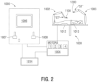
- robotic surgical system 1000 exemplifying the aspects and features of the present disclosure is shown generally identified by reference numeral 1000.
- robotic surgical system 1000 is generally described. Aspects and features of robotic surgical system 1000 not germane to the understanding of the present disclosure are omitted to avoid obscuring the aspects and features of the present disclosure in unnecessary detail.
- Robotic surgical system 1000 generally includes a plurality of robot arms 1002, 1003; a control device 1004; and an operating console 1005 coupled with control device 1004.
- Operating console 1005 may include a display device 1006, which may be set up in particular to display three-dimensional images; and manual input devices 1007, 1008, by means of which a person (not shown), for example a surgeon, may be able to telemanipulate robot arms 1002, 1003.
- Robotic surgical system 1000 may be configured for use on a patient 1013 lying on a patient table 1012 to be treated in a minimally invasive or other suitable manner.
- Robotic surgical system 1000 may further include a database 1014, in particular coupled to control device 1004, in which are stored, for example, pre-operative data from patient 1013 and/or anatomical atlases.
- Each of the robot arms 1002, 1003 may include a plurality of members, which are connected through joints, to which may be attached, for example, a surgical tool "ST" supporting an end effector assembly 1100, 1200.
- End effector assembly 1100 may be configured as an articulating ultrasonic surgical instrument similarly as detailed above with respect to instrument 10 ( FIGS. 1A and 1B ) except that housing 110 of handle assembly 100 ( FIGS. 1A and 1B ) is configured to connect to robot arm 1002 and any manual controls or features of instrument 10 ( FIGS. 1A and 1B ) are modified appropriately such that manipulation, actuation, and the other functions of instrument 10 ( FIGS. 1A and 1B ) are effected by robot arm 1002 rather than manually by a user.
- End effector 1200 may be any other suitable surgical end effector, e.g., an endoscopic camera, other surgical tool, etc.
- Robot arms 1002, 1003 may be driven by electric drives, e.g., motors, that are connected to control device 1004.
- Control device 1004 e.g., a computer
- Control device 1004 may be configured to activate the motors, in particular by means of a computer program, in such a way that robot arms 1002, 1003, and, thus, the surgical tools "ST" (including end effectors 1100, 1200) execute a desired movement and/or function according to a corresponding input from manual input devices 1007, 1008, respectively.
- Control device 1004 may also be configured in such a way that it regulates the movement of robot arms 1002, 1003 and/or of the motors.
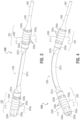
- transducer assembly 230 is shown in non-articulated (e.g., linear) and articulated conditions, respectively.
- transducer assembly 230 includes proximal and distal transducers 232, 234, respectively, flexible connector 236 extending between proximal and distal transducers 232, 234, respectively, ultrasonic horn 238 extending distally from distal transducer 234, and ultrasonic blade 282 (which serves as the blade of end effector 280) extending distally from ultrasonic horn 238.
- Proximal transducer 232 may be supported within elongated shaft 210 ( FIG. 1A ) in substantially fixed position relative thereto and includes a proximal end mass 233a, a distal end mass 233b, and a stack of piezoelectric elements 233c disposed between proximal and distal end masses 233a, 233b, respectively.
- Proximal transducer 232 further includes a stress rod 233d engaged with the distal end mass 233b, e.g., via a threaded, welded, or other suitable engagement, and extending proximally through the stack of piezoelectric elements 233c and proximal end mass 233a.
- Proximal transducer 232 additionally includes first and second electrodes 233f, 233g electrically coupled between piezoelectric elements of the stack of piezoelectric elements 233c to enable energization thereof to produce ultrasonic energy. Electrical lead wires (not shown) connect first and second electrodes 233f, 233g with generator assembly 300 ( FIG.
- Distal transducer 234 includes a proximal end mass 235a, a distal end mass 235b, and a stack of piezoelectric elements 235c disposed between proximal and distal end masses 235a, 235b, respectively.
- a stress rod (not shown) extend between proximal end mass 235a, a distal end mass 235b and through the stack of piezoelectric elements 235c to maintain the stack of piezoelectric elements 235c under a longitudinal pre-compression between proximal and distal end masses 235a, 235b, respectively.
- Distal transducer 234 additionally includes first and second electrodes 235f, 235g electrically coupled between piezoelectric elements of the stack of piezoelectric elements 235c to enable energization thereof to produce ultrasonic energy.
- Electrical lead wires (not shown) connect first and second electrodes 235f, 235g with generator assembly 300 ( FIG. 1A ) to enable an electrical drive signal generated by generator assembly 300 ( FIG. 1A ) to be imparted to the stack of piezoelectric elements 235c of distal transducer assembly 234 to energize the stack of piezoelectric elements 235c to produce ultrasonic energy.
- the first and second electrodes 235f, 235g of distal transducer 234 may be energized via a commonly controlled and output electrical drive signal (via common or separate leads) as the first and second electrodes 233f, 233g of proximal transducer 234, respectively.
- proximal and distal transducers 232, 234, respectively may be energized via independently controlled and output electrical drive signals from generator assembly 300 ( FIG. 1A ).
- activation button 120 itself or an additional activation button (not shown) enable activation at different levels, e.g., a first activation corresponding to a LOW power mode (producing a relatively low velocity of ultrasonic blade 282) and a HIGH power mode (producing a relatively high velocity of ultrasonic blade 282).
- a first activation corresponding to a LOW power mode producing a relatively low velocity of ultrasonic blade 282
- a HIGH power mode producing a relatively high velocity of ultrasonic blade 282
- only one of the transducers 232, 234 may be activated in the LOW power mode while both of the transducers 232, 234 are activated in the HIGH power moved.
- both transducers 232, 234 may be activated in both modes (with one or both of the transducers 232, 234 being activated to a different power level in the different modes).
- Flexible connector 236 includes a proximal hub 237a, a distal hub 237b, and a body 237c extending between the proximal and distal hubs 237a, 237b, respectively.
- Proximal hub 237a is unitarily formed with or engaged to distal mass 233b of proximal transducer 232 while distal hub 237b is unitarily formed with or engaged to proximal mass 235a of distal transducer 234.
- Body 237c is flexible in at least one direction. In some configurations, as illustrated, body 237c is formed as a band of material capable of flexing in directions perpendicular to the broad side surfaces of the band of material.
- body 237c may include, for example, one or more reduced-dimension portions (to increase flexibility in one or more directions), flexure hinge sections, ball-and-socket joints, pinned joints, combinations thereof, and/or other suitable articulation features to enable articulation of flexible connector 236 in one or more directions.
- Ultrasonic horn 238 is unitarily formed with or engaged to distal mass 235b of distal transducer 234 and extends distally therefrom.
- Blade 282 is unitarily formed with or engaged with ultrasonic horn 238 and extend distally therefrom. In some configurations, ultrasonic horn 238 is omitted and blade 282 is directly formed with or engaged to distal mass 235b.
- Blade 282 defines a straight, cylindrical configuration. As detailed above, this configuration enables clamping of tissue between blade 282 and jaw 284 ( FIG. 1A ) at any rotational orientation of jaw 284 ( FIG. 1A ) relative to blade 282 (in embodiments where jaw 284 ( FIG. 1A ) is rotatable about blade 282).
- Blade 282 may alternatively define other suitable cross-sectional configurations, e.g., polygonal configurations, and/or may include tapers along the length thereof. Further, as an alternative to defining a straight configuration, blade 282 may define a curved and/or angled configuration including one or more curved/angled portions curved/angled in similar or different directions.
- transducer assembly 230 must define a sufficiently small diameter so as to enable operable receipt within elongated shaft 210 and support shaft 286. More specifically, proximal and distal transducers 232, 234, respectively, in some configurations, define outer diameters less than about 12mm, less than about 10mm, or less than about 8mm. As a result, the diameters of the piezoelectric elements (or largest cross-sectional dimension for non-circular elements) of the stacks of piezoelectric elements 233c, 235c are limited which, in turn, limits the ultrasonic energy capable of being generated by the proximal and distal transducers 232, 234, respectively. Further, the physics of longitudinal standing waves renders the increased energy produced by increasing the number of the piezoelectric elements in the stack relatively minimal.
- transducer assembly 230 regardless of whether transducer assembly 230 is disposed in an unarticulated condition ( FIG. 3 ) or an articulated condition ( FIG. 4 ), enables ultrasonic energy produced by proximal transducer 232 to be transmitted along flexible connector 236, distal transducer 234, and ultrasonic horn 238 to blade 282 and also enables ultrasonic energy produced by distal transducer 234 to be transmitted along ultrasonic horn 238 to blade 282.
- the overall amount of ultrasonic energy provided at blade 282 can be increased without requiring an increase in the overall diameter of the system.
- proximal and distal transducers 232, 234 are disposed at or near node points of the system.
- first, second, and third transducers 2232 may be provided with first and second flexible connectors 2236 disposed therebetween and an ultrasonic horn 2238 and blade 2282 extending distally from the distal-most transducer 2232.
- first, second, third, and fourth transducers 3232 may be provided with first and second flexible connectors 3236 connecting the first and second transducers 3232 and third and fourth transducers 3232, respectively, a rigid connector 3236' connecting the second and third transducers 3232 with one another, and with one another and a with one another, and an ultrasonic horn 3238 and blade 3282 extending distally from the distal-most transducer 3232.
- FIG. 5C illustrates still another example, wherein first and second transducers 4232 are connected by a flexible connector 4236, an ultrasonic horn 4238 extends distally from the distal-most transducer 4232, a waveguide 4236' extends distally from the ultrasonic horn 4238, and a blade 4282 is defined at or engaged to a distal end of the waveguide 4236'.
- First, second, and third transducers 5232 are illustrated in FIG. 5D , wherein the first and second transducers 5232 are connected via a rigid connector 5236' and the second and third transducers 5232 are connected by a flexible connector 5236.
- An ultrasonic horn 5238 and blade 5282 extend distally from the distal-most transducer 5232.
- Other configurations including combinations of the above component or any other suitable components interconnecting multiple transducers with an ultrasonic blade are also contemplated.
- the transducers, flexible connectors, ultrasonic horns, and blade of the configurations of FIGS. 5A-5D may be similar to and include any of the features of transducer assembly 230 ( FIGS. 3 and 4 ) as detailed above. Further, the multiple flexible connectors may be oriented to allow articulation in the same plane to allow a greater degree of flexibility or in different planes to allow multidimensional articulation.
Landscapes
- Health & Medical Sciences (AREA)
- Surgery (AREA)
- Engineering & Computer Science (AREA)
- Life Sciences & Earth Sciences (AREA)
- Animal Behavior & Ethology (AREA)
- Molecular Biology (AREA)
- Veterinary Medicine (AREA)
- Public Health (AREA)
- Biomedical Technology (AREA)
- Heart & Thoracic Surgery (AREA)
- Medical Informatics (AREA)
- Nuclear Medicine, Radiotherapy & Molecular Imaging (AREA)
- Mechanical Engineering (AREA)
- General Health & Medical Sciences (AREA)
- Dentistry (AREA)
- Orthopedic Medicine & Surgery (AREA)
- Vascular Medicine (AREA)
- Surgical Instruments (AREA)
Claims (15)
- Chirurgisches Ultraschallinstrument, umfassend:ein Gehäuse (110);einen länglichen Schaft (210), der sich distal von dem Gehäuse erstreckt;einen Endeffektor (280), der sich distal von dem länglichen Schaft erstreckt, wobei der Endeffektor eine Backe (284) und eine Ultraschallklinge (282) einschließt, wobei die Backe ausgestaltet ist, um relativ zu der Ultraschallklinge von einer offenen Position zu einer Klemmposition zu schwenken, um Gewebe dazwischen einzuklemmen; undeine Wandlerbaugruppe (230), die mindestens teilweise innerhalb des länglichen Schafts angeordnet ist, wobei die Wandlerbaugruppe distal von dem Gehäuse beabstandet ist und proximale und distale Wandler (232, 234) einschließt, die mittels eines Verbinders (236) verbunden sind,wobei die Ultraschallklinge mit dem distalen Wandler so verbunden ist, dass Ultraschallenergie, die durch den proximalen Wandler produziert wird, entlang des Verbinders und des distalen Wandlers an die Ultraschallklinge übertragen wird, und so, dass Ultraschallenergie, die durch den distalen Wandler produziert wird, an die Ultraschallklinge übertragen wird,wobei der Verbinder ein flexibler Verbinder (236) ist, der ausgestaltet ist, um sich in mindestens einer Richtung gelenkig zu bewegen, dadurch gekennzeichnet, dass der längliche Schaft einen Gelenkabschnitt (220) einschließt, der ausgestaltet ist, um den Endeffektor relativ zu der Längsachse des länglichen Schafts gelenkig zu bewegen, undwobei der flexible Verbinder sich durch den Gelenkabschnitt hindurch erstreckt, so dass der proximale Wandler proximal zu dem Gelenkabschnitt angeordnet ist, und so, dass der distale Wandler distal zu dem Gelenkabschnitt angeordnet ist.
- Chirurgisches Ultraschallinstrument nach Anspruch 1, wobei der flexible Verbinder als Materialband gebildet ist.
- Chirurgisches Ultraschallinstrument nach Anspruch 1, wobei der längliche Schaft einen Außendurchmesser von weniger als etwa 15 mm definiert.
- Chirurgisches Ultraschallinstrument nach Anspruch 1, wobei der längliche Schaft einen Außendurchmesser von weniger als etwa 8 mm definiert.
- Chirurgisches Ultraschallinstrument nach Anspruch 1, wobei der längliche Schaft einen Außendurchmesser zwischen etwa 5 mm und etwa 8 mm definiert.
- Chirurgisches Ultraschallinstrument nach Anspruch 1, wobei jeder von dem proximalen und dem distalen Wandler einen Außendurchmesser von weniger als etwa 15 mm definiert.
- Chirurgisches Ultraschallinstrument nach Anspruch 1, wobei jeder von dem proximalen und dem distalen Wandler einen Außendurchmesser von weniger als etwa 8 mm definiert.
- Chirurgisches Ultraschallinstrument nach Anspruch 1, wobei jeder von dem proximalen und dem distalen Wandler einen Außendurchmesser zwischen etwa 5 mm und etwa 8 mm definiert.
- Chirurgisches Ultraschallinstrument nach Anspruch 1, wobei jeder von dem proximalen und dem distalen Wandler (232, 234) einschließt:eine proximale Masse (233a, 235a);eine distale Masse (233b, 235b);einen Stapel piezoelektrischer Elemente (233c, 235c), der zwischen der proximalen und der distalen Masse unter Vorkompression gehalten wird; underste und zweite Elektroden (233f, 233g, 235f, 235g), die elektrisch an den Stapel der piezoelektrischen Elemente gekoppelt sind.
- Chirurgisches Ultraschallinstrument nach Anspruch 1, wobei die Ultraschallklinge eine zylindrische Konfiguration definiert.
- Chirurgisches Ultraschallinstrument nach Anspruch 10, wobei die Backe so ausgestaltet ist, dass sie um die Ultraschallklinge rotiert, so dass die Backe in der Lage ist, Gewebe zwischen der Backe und der Klinge in jedweder Rotationsorientierung der Backe relativ zu der Klinge einzuklemmen.
- Chirurgisches Ultraschallinstrument nach Anspruch 1, wobei der erste und der zweite Wandler um Vibrationsknotenpunkte herum angeordnet sind.
- Chirurgisches Ultraschallinstrument nach Anspruch 1, wobei das Gehäuse vorgesehen ist, um mit einem Roboterarm eines Roboterchirurgiesystems verbunden zu werden.
- Chirurgisches Ultraschallinstrument nach Anspruch 1, wobei das Gehäuse mindestens eine manuelle Steuerung einschließt.
- Chirurgisches Ultraschallinstrument nach Anspruch 1, wobei der proximale und der distale Wandler durch unabhängige elektrische Antriebssignale angetrieben werden.
Applications Claiming Priority (2)
| Application Number | Priority Date | Filing Date | Title |
|---|---|---|---|
| US202063025337P | 2020-05-15 | 2020-05-15 | |
| PCT/US2021/030438 WO2021231118A1 (en) | 2020-05-15 | 2021-05-03 | Articulating ultrasonic surgical instruments and systems |
Publications (2)
| Publication Number | Publication Date |
|---|---|
| EP4149375A1 EP4149375A1 (de) | 2023-03-22 |
| EP4149375B1 true EP4149375B1 (de) | 2025-01-08 |
Family
ID=76076490
Family Applications (1)
| Application Number | Title | Priority Date | Filing Date |
|---|---|---|---|
| EP21727693.0A Active EP4149375B1 (de) | 2020-05-15 | 2021-05-03 | Gelenkige chirurgische ultraschallinstrumente und systeme |
Country Status (4)
| Country | Link |
|---|---|
| US (1) | US12564418B2 (de) |
| EP (1) | EP4149375B1 (de) |
| CN (1) | CN115605147A (de) |
| WO (1) | WO2021231118A1 (de) |
Families Citing this family (2)
| Publication number | Priority date | Publication date | Assignee | Title |
|---|---|---|---|---|
| CN117045314A (zh) * | 2023-09-26 | 2023-11-14 | 上海圣哲医疗科技有限公司 | 手术刀 |
| CN117883152A (zh) * | 2024-03-13 | 2024-04-16 | 苏州康多机器人有限公司 | 末端执行器及超声切割止血系统 |
Family Cites Families (47)
| Publication number | Priority date | Publication date | Assignee | Title |
|---|---|---|---|---|
| US5792135A (en) | 1996-05-20 | 1998-08-11 | Intuitive Surgical, Inc. | Articulated surgical instrument for performing minimally invasive surgery with enhanced dexterity and sensitivity |
| US5897523A (en) | 1998-04-13 | 1999-04-27 | Ethicon Endo-Surgery, Inc. | Articulating ultrasonic surgical instrument |
| US6589200B1 (en) | 1999-02-22 | 2003-07-08 | Ethicon Endo-Surgery, Inc. | Articulating ultrasonic surgical shears |
| JP4338260B2 (ja) * | 1999-06-24 | 2009-10-07 | アロカ株式会社 | 超音波手術装置 |
| US20080214967A1 (en) | 2004-02-17 | 2008-09-04 | Ernest Aranyi | Ultrasonic surgical instrument |
| US6793635B2 (en) * | 2002-06-28 | 2004-09-21 | Ethicon, Inc. | Devices having deployable ultrasound transducers and method of use of same |
| JP4300169B2 (ja) | 2004-09-10 | 2009-07-22 | アロカ株式会社 | 超音波手術器 |
| JP4287354B2 (ja) | 2004-10-25 | 2009-07-01 | 株式会社日立製作所 | 手術器具 |
| US8512365B2 (en) * | 2007-07-31 | 2013-08-20 | Ethicon Endo-Surgery, Inc. | Surgical instruments |
| JP5017076B2 (ja) | 2007-12-21 | 2012-09-05 | テルモ株式会社 | マニピュレータシステム及びマニピュレータの制御方法 |
| WO2011114924A1 (ja) | 2010-03-15 | 2011-09-22 | テルモ株式会社 | 医療用マニピュレータ |
| CN106943165B (zh) | 2011-11-23 | 2021-08-17 | 利思梅德株式会社 | 手术用器械的末端器具 |
| US8617203B2 (en) | 2011-12-02 | 2013-12-31 | Ethicon Endo-Surgery, Inc. | Jaw assembly for surgical devices |
| JP5875857B2 (ja) | 2011-12-26 | 2016-03-02 | オリンパス株式会社 | 超音波振動デバイスおよび超音波医療装置 |
| US20140005705A1 (en) | 2012-06-29 | 2014-01-02 | Ethicon Endo-Surgery, Inc. | Surgical instruments with articulating shafts |
| US9408622B2 (en) | 2012-06-29 | 2016-08-09 | Ethicon Endo-Surgery, Llc | Surgical instruments with articulating shafts |
| US9393037B2 (en) | 2012-06-29 | 2016-07-19 | Ethicon Endo-Surgery, Llc | Surgical instruments with articulating shafts |
| US20140005702A1 (en) * | 2012-06-29 | 2014-01-02 | Ethicon Endo-Surgery, Inc. | Ultrasonic surgical instruments with distally positioned transducers |
| US9351754B2 (en) | 2012-06-29 | 2016-05-31 | Ethicon Endo-Surgery, Llc | Ultrasonic surgical instruments with distally positioned jaw assemblies |
| US9314308B2 (en) | 2013-03-13 | 2016-04-19 | Ethicon Endo-Surgery, Llc | Robotic ultrasonic surgical device with articulating end effector |
| US10172636B2 (en) | 2013-09-17 | 2019-01-08 | Ethicon Llc | Articulation features for ultrasonic surgical instrument |
| JP6270505B2 (ja) * | 2014-01-27 | 2018-01-31 | オリンパス株式会社 | 積層型超音波振動デバイス、積層型超音波振動デバイスの製造方法および超音波医療装置 |
| US10258363B2 (en) | 2014-04-22 | 2019-04-16 | Ethicon Llc | Method of operating an articulating ultrasonic surgical instrument |
| US20160302819A1 (en) | 2015-04-16 | 2016-10-20 | Ethicon Endo-Surgery, Llc | Ultrasonic surgical instrument with articulating end effector having a curved blade |
| US10342567B2 (en) | 2015-04-16 | 2019-07-09 | Ethicon Llc | Ultrasonic surgical instrument with opposing thread drive for end effector articulation |
| US10034683B2 (en) | 2015-04-16 | 2018-07-31 | Ethicon Llc | Ultrasonic surgical instrument with rigidizing articulation drive members |
| US10226274B2 (en) | 2015-04-16 | 2019-03-12 | Ethicon Llc | Ultrasonic surgical instrument with articulation joint having plurality of locking positions |
| US10413316B2 (en) * | 2015-11-17 | 2019-09-17 | Covidien Lp | Articulating ultrasonic surgical instruments and systems |
| US10413351B2 (en) * | 2015-11-24 | 2019-09-17 | Ethicon Llc | Surgical device with biased knife |
| US10492819B2 (en) | 2016-04-01 | 2019-12-03 | Ethicon Llc | Surgical instrument with dual mode articulation drive |
| US10575836B2 (en) | 2016-04-04 | 2020-03-03 | Ethicon Llc | Surgical instrument with selectively locked articulation assembly |
| US10405876B2 (en) | 2016-04-05 | 2019-09-10 | Ethicon Llc | Articulation joint for surgical instrument |
| US10245064B2 (en) | 2016-07-12 | 2019-04-02 | Ethicon Llc | Ultrasonic surgical instrument with piezoelectric central lumen transducer |
| US10925630B2 (en) | 2018-06-19 | 2021-02-23 | Ethicon Llc | Surgical devices and systems with rotating end effector assemblies having an ultrasonic blade |
| US10582945B2 (en) | 2018-03-20 | 2020-03-10 | Ethicon Llc | Surgical devices and systems with rotating end effector assemblies having an ultrasonic blade |
| US11033293B2 (en) | 2017-07-19 | 2021-06-15 | Cilag Gmbh International | Ultrasonic transducer to blade acoustic coupling, connections, and configurations |
| US20190021752A1 (en) | 2017-07-19 | 2019-01-24 | Ethicon Llc | Ultrasonic transducer to blade acoustic coupling, connections, and configurations |
| US10912581B2 (en) | 2017-08-29 | 2021-02-09 | Ethicon Llc | Electrically-powered surgical systems with articulation-compensated ultrasonic energy delivery |
| US11246621B2 (en) | 2018-01-29 | 2022-02-15 | Covidien Lp | Ultrasonic transducers and ultrasonic surgical instruments including the same |
| US12426909B2 (en) | 2019-07-08 | 2025-09-30 | Covidien Lp | Ultrasonic transducer assembly and ultrasonic surgical instrument incorporating the same |
| US11612409B2 (en) * | 2019-08-30 | 2023-03-28 | Cilag Gmbh International | Ultrasonic transducer alignment of an articulating ultrasonic surgical instrument |
| EP4110204A1 (de) | 2020-02-28 | 2023-01-04 | Covidien LP | Gelenkige chirurgische ultraschallinstrumente und systeme |
| US12575850B2 (en) | 2020-03-02 | 2026-03-17 | Covidien Lp | Articulating ultrasonic surgical instruments and systems |
| WO2021202035A1 (en) | 2020-04-02 | 2021-10-07 | Covidien Lp | Articulating ultrasonic surgical instruments and systems |
| US12161355B2 (en) | 2020-05-18 | 2024-12-10 | Covidien Lp | Articulating ultrasonic surgical instruments and systems |
| US11766275B2 (en) | 2020-05-18 | 2023-09-26 | Covidien Lp | Articulating ultrasonic surgical instruments and systems |
| US20210369295A1 (en) | 2020-06-02 | 2021-12-02 | Covidien Lp | Ultrasonic transducer casing, ultrasonic transducer assembly, and ultrasonic surgical instrument |
-
2021
- 2021-05-03 EP EP21727693.0A patent/EP4149375B1/de active Active
- 2021-05-03 CN CN202180034992.8A patent/CN115605147A/zh active Pending
- 2021-05-03 WO PCT/US2021/030438 patent/WO2021231118A1/en not_active Ceased
- 2021-05-03 US US17/924,596 patent/US12564418B2/en active Active
Also Published As
| Publication number | Publication date |
|---|---|
| WO2021231118A1 (en) | 2021-11-18 |
| CN115605147A (zh) | 2023-01-13 |
| US12564418B2 (en) | 2026-03-03 |
| US20230172628A1 (en) | 2023-06-08 |
| EP4149375A1 (de) | 2023-03-22 |
Similar Documents
| Publication | Publication Date | Title |
|---|---|---|
| US12048449B2 (en) | Articulating ultrasonic surgical instruments and systems | |
| US6090120A (en) | Articulating ultrasonic surgical instrument | |
| US20250281198A1 (en) | Articulating ultrasonic surgical instruments and systems | |
| US6454782B1 (en) | Actuation mechanism for surgical instruments | |
| US6589200B1 (en) | Articulating ultrasonic surgical shears | |
| US20020177843A1 (en) | Robotic surgical tool with ultrasound cauterizing and cutting instrument | |
| CN104540461A (zh) | 具有定位在远侧的换能器的超声外科器械 | |
| CN113679450B (zh) | 铰接超声手术仪器和系统 | |
| EP4114287B1 (de) | Gelenkige chirurgische ultraschallinstrumente und systeme | |
| EP4149375B1 (de) | Gelenkige chirurgische ultraschallinstrumente und systeme | |
| US20230095787A1 (en) | Articulating ultrasonic surgical instruments and systems | |
| US20230240702A1 (en) | Articulating ultrasonic surgical instruments and systems | |
| US12569271B2 (en) | Surgical instruments, systems, and methods incorporating an ultrasonic transducer | |
| US12484926B2 (en) | Surgical instruments, systems, and methods incorporating an offset end effector | |
| US20230098378A1 (en) | Articulating ultrasonic surgical instruments and systems |
Legal Events
| Date | Code | Title | Description |
|---|---|---|---|
| STAA | Information on the status of an ep patent application or granted ep patent |
Free format text: STATUS: UNKNOWN |
|
| STAA | Information on the status of an ep patent application or granted ep patent |
Free format text: STATUS: THE INTERNATIONAL PUBLICATION HAS BEEN MADE |
|
| PUAI | Public reference made under article 153(3) epc to a published international application that has entered the european phase |
Free format text: ORIGINAL CODE: 0009012 |
|
| STAA | Information on the status of an ep patent application or granted ep patent |
Free format text: STATUS: REQUEST FOR EXAMINATION WAS MADE |
|
| 17P | Request for examination filed |
Effective date: 20221206 |
|
| AK | Designated contracting states |
Kind code of ref document: A1 Designated state(s): AL AT BE BG CH CY CZ DE DK EE ES FI FR GB GR HR HU IE IS IT LI LT LU LV MC MK MT NL NO PL PT RO RS SE SI SK SM TR |
|
| DAV | Request for validation of the european patent (deleted) | ||
| DAX | Request for extension of the european patent (deleted) | ||
| STAA | Information on the status of an ep patent application or granted ep patent |
Free format text: STATUS: EXAMINATION IS IN PROGRESS |
|
| 17Q | First examination report despatched |
Effective date: 20240229 |
|
| GRAP | Despatch of communication of intention to grant a patent |
Free format text: ORIGINAL CODE: EPIDOSNIGR1 |
|
| STAA | Information on the status of an ep patent application or granted ep patent |
Free format text: STATUS: GRANT OF PATENT IS INTENDED |
|
| RIC1 | Information provided on ipc code assigned before grant |
Ipc: A61B 17/22 20060101ALN20240729BHEP Ipc: A61B 17/32 20060101AFI20240729BHEP |
|
| INTG | Intention to grant announced |
Effective date: 20240821 |
|
| GRAS | Grant fee paid |
Free format text: ORIGINAL CODE: EPIDOSNIGR3 |
|
| GRAA | (expected) grant |
Free format text: ORIGINAL CODE: 0009210 |
|
| STAA | Information on the status of an ep patent application or granted ep patent |
Free format text: STATUS: THE PATENT HAS BEEN GRANTED |
|
| AK | Designated contracting states |
Kind code of ref document: B1 Designated state(s): AL AT BE BG CH CY CZ DE DK EE ES FI FR GB GR HR HU IE IS IT LI LT LU LV MC MK MT NL NO PL PT RO RS SE SI SK SM TR |
|
| REG | Reference to a national code |
Ref country code: GB Ref legal event code: FG4D |
|
| REG | Reference to a national code |
Ref country code: CH Ref legal event code: EP |
|
| REG | Reference to a national code |
Ref country code: DE Ref legal event code: R096 Ref document number: 602021024670 Country of ref document: DE |
|
| REG | Reference to a national code |
Ref country code: IE Ref legal event code: FG4D |
|
| REG | Reference to a national code |
Ref country code: LT Ref legal event code: MG9D |
|
| REG | Reference to a national code |
Ref country code: NL Ref legal event code: MP Effective date: 20250108 |
|
| REG | Reference to a national code |
Ref country code: AT Ref legal event code: MK05 Ref document number: 1757819 Country of ref document: AT Kind code of ref document: T Effective date: 20250108 |
|
| PG25 | Lapsed in a contracting state [announced via postgrant information from national office to epo] |
Ref country code: NL Free format text: LAPSE BECAUSE OF FAILURE TO SUBMIT A TRANSLATION OF THE DESCRIPTION OR TO PAY THE FEE WITHIN THE PRESCRIBED TIME-LIMIT Effective date: 20250108 |
|
| PG25 | Lapsed in a contracting state [announced via postgrant information from national office to epo] |
Ref country code: RS Free format text: LAPSE BECAUSE OF FAILURE TO SUBMIT A TRANSLATION OF THE DESCRIPTION OR TO PAY THE FEE WITHIN THE PRESCRIBED TIME-LIMIT Effective date: 20250408 |
|
| PG25 | Lapsed in a contracting state [announced via postgrant information from national office to epo] |
Ref country code: FI Free format text: LAPSE BECAUSE OF FAILURE TO SUBMIT A TRANSLATION OF THE DESCRIPTION OR TO PAY THE FEE WITHIN THE PRESCRIBED TIME-LIMIT Effective date: 20250108 |
|
| PG25 | Lapsed in a contracting state [announced via postgrant information from national office to epo] |
Ref country code: PL Free format text: LAPSE BECAUSE OF FAILURE TO SUBMIT A TRANSLATION OF THE DESCRIPTION OR TO PAY THE FEE WITHIN THE PRESCRIBED TIME-LIMIT Effective date: 20250108 |
|
| PGFP | Annual fee paid to national office [announced via postgrant information from national office to epo] |
Ref country code: DE Payment date: 20250423 Year of fee payment: 5 |
|
| PG25 | Lapsed in a contracting state [announced via postgrant information from national office to epo] |
Ref country code: ES Free format text: LAPSE BECAUSE OF FAILURE TO SUBMIT A TRANSLATION OF THE DESCRIPTION OR TO PAY THE FEE WITHIN THE PRESCRIBED TIME-LIMIT Effective date: 20250108 |
|
| PG25 | Lapsed in a contracting state [announced via postgrant information from national office to epo] |
Ref country code: IS Free format text: LAPSE BECAUSE OF FAILURE TO SUBMIT A TRANSLATION OF THE DESCRIPTION OR TO PAY THE FEE WITHIN THE PRESCRIBED TIME-LIMIT Effective date: 20250508 Ref country code: NO Free format text: LAPSE BECAUSE OF FAILURE TO SUBMIT A TRANSLATION OF THE DESCRIPTION OR TO PAY THE FEE WITHIN THE PRESCRIBED TIME-LIMIT Effective date: 20250408 |
|
| PG25 | Lapsed in a contracting state [announced via postgrant information from national office to epo] |
Ref country code: HR Free format text: LAPSE BECAUSE OF FAILURE TO SUBMIT A TRANSLATION OF THE DESCRIPTION OR TO PAY THE FEE WITHIN THE PRESCRIBED TIME-LIMIT Effective date: 20250108 |
|
| PG25 | Lapsed in a contracting state [announced via postgrant information from national office to epo] |
Ref country code: LV Free format text: LAPSE BECAUSE OF FAILURE TO SUBMIT A TRANSLATION OF THE DESCRIPTION OR TO PAY THE FEE WITHIN THE PRESCRIBED TIME-LIMIT Effective date: 20250108 Ref country code: PT Free format text: LAPSE BECAUSE OF FAILURE TO SUBMIT A TRANSLATION OF THE DESCRIPTION OR TO PAY THE FEE WITHIN THE PRESCRIBED TIME-LIMIT Effective date: 20250508 |
|
| PG25 | Lapsed in a contracting state [announced via postgrant information from national office to epo] |
Ref country code: BG Free format text: LAPSE BECAUSE OF FAILURE TO SUBMIT A TRANSLATION OF THE DESCRIPTION OR TO PAY THE FEE WITHIN THE PRESCRIBED TIME-LIMIT Effective date: 20250108 Ref country code: GR Free format text: LAPSE BECAUSE OF FAILURE TO SUBMIT A TRANSLATION OF THE DESCRIPTION OR TO PAY THE FEE WITHIN THE PRESCRIBED TIME-LIMIT Effective date: 20250409 |
|
| PG25 | Lapsed in a contracting state [announced via postgrant information from national office to epo] |
Ref country code: AT Free format text: LAPSE BECAUSE OF FAILURE TO SUBMIT A TRANSLATION OF THE DESCRIPTION OR TO PAY THE FEE WITHIN THE PRESCRIBED TIME-LIMIT Effective date: 20250108 |
|
| PG25 | Lapsed in a contracting state [announced via postgrant information from national office to epo] |
Ref country code: SE Free format text: LAPSE BECAUSE OF FAILURE TO SUBMIT A TRANSLATION OF THE DESCRIPTION OR TO PAY THE FEE WITHIN THE PRESCRIBED TIME-LIMIT Effective date: 20250108 |
|
| PG25 | Lapsed in a contracting state [announced via postgrant information from national office to epo] |
Ref country code: SM Free format text: LAPSE BECAUSE OF FAILURE TO SUBMIT A TRANSLATION OF THE DESCRIPTION OR TO PAY THE FEE WITHIN THE PRESCRIBED TIME-LIMIT Effective date: 20250108 |
|
| REG | Reference to a national code |
Ref country code: DE Ref legal event code: R097 Ref document number: 602021024670 Country of ref document: DE |
|
| PG25 | Lapsed in a contracting state [announced via postgrant information from national office to epo] |
Ref country code: DK Free format text: LAPSE BECAUSE OF FAILURE TO SUBMIT A TRANSLATION OF THE DESCRIPTION OR TO PAY THE FEE WITHIN THE PRESCRIBED TIME-LIMIT Effective date: 20250108 |
|
| PG25 | Lapsed in a contracting state [announced via postgrant information from national office to epo] |
Ref country code: EE Free format text: LAPSE BECAUSE OF FAILURE TO SUBMIT A TRANSLATION OF THE DESCRIPTION OR TO PAY THE FEE WITHIN THE PRESCRIBED TIME-LIMIT Effective date: 20250108 Ref country code: CZ Free format text: LAPSE BECAUSE OF FAILURE TO SUBMIT A TRANSLATION OF THE DESCRIPTION OR TO PAY THE FEE WITHIN THE PRESCRIBED TIME-LIMIT Effective date: 20250108 |
|
| PG25 | Lapsed in a contracting state [announced via postgrant information from national office to epo] |
Ref country code: RO Free format text: LAPSE BECAUSE OF FAILURE TO SUBMIT A TRANSLATION OF THE DESCRIPTION OR TO PAY THE FEE WITHIN THE PRESCRIBED TIME-LIMIT Effective date: 20250108 |
|
| PG25 | Lapsed in a contracting state [announced via postgrant information from national office to epo] |
Ref country code: SK Free format text: LAPSE BECAUSE OF FAILURE TO SUBMIT A TRANSLATION OF THE DESCRIPTION OR TO PAY THE FEE WITHIN THE PRESCRIBED TIME-LIMIT Effective date: 20250108 |
|
| PLBE | No opposition filed within time limit |
Free format text: ORIGINAL CODE: 0009261 |
|
| STAA | Information on the status of an ep patent application or granted ep patent |
Free format text: STATUS: NO OPPOSITION FILED WITHIN TIME LIMIT |
|
| REG | Reference to a national code |
Ref country code: CH Ref legal event code: L10 Free format text: ST27 STATUS EVENT CODE: U-0-0-L10-L00 (AS PROVIDED BY THE NATIONAL OFFICE) Effective date: 20251119 |
|
| 26N | No opposition filed |
Effective date: 20251009 |
|
| REG | Reference to a national code |
Ref country code: CH Ref legal event code: H13 Free format text: ST27 STATUS EVENT CODE: U-0-0-H10-H13 (AS PROVIDED BY THE NATIONAL OFFICE) Effective date: 20251223 |
|
| PG25 | Lapsed in a contracting state [announced via postgrant information from national office to epo] |
Ref country code: LU Free format text: LAPSE BECAUSE OF NON-PAYMENT OF DUE FEES Effective date: 20250503 |
|
| PG25 | Lapsed in a contracting state [announced via postgrant information from national office to epo] |
Ref country code: CH Free format text: LAPSE BECAUSE OF NON-PAYMENT OF DUE FEES Effective date: 20250531 |
|
| PG25 | Lapsed in a contracting state [announced via postgrant information from national office to epo] |
Ref country code: IT Free format text: LAPSE BECAUSE OF FAILURE TO SUBMIT A TRANSLATION OF THE DESCRIPTION OR TO PAY THE FEE WITHIN THE PRESCRIBED TIME-LIMIT Effective date: 20250108 |
|
| REG | Reference to a national code |
Ref country code: BE Ref legal event code: MM Effective date: 20250531 |
|
| PG25 | Lapsed in a contracting state [announced via postgrant information from national office to epo] |
Ref country code: MC Free format text: LAPSE BECAUSE OF FAILURE TO SUBMIT A TRANSLATION OF THE DESCRIPTION OR TO PAY THE FEE WITHIN THE PRESCRIBED TIME-LIMIT Effective date: 20250108 |
|
| PGFP | Annual fee paid to national office [announced via postgrant information from national office to epo] |
Ref country code: GB Payment date: 20260317 Year of fee payment: 6 |
|
| PG25 | Lapsed in a contracting state [announced via postgrant information from national office to epo] |
Ref country code: IE Free format text: LAPSE BECAUSE OF NON-PAYMENT OF DUE FEES Effective date: 20250503 |
|
| PG25 | Lapsed in a contracting state [announced via postgrant information from national office to epo] |
Ref country code: BE Free format text: LAPSE BECAUSE OF NON-PAYMENT OF DUE FEES Effective date: 20250531 |
|
| PG25 | Lapsed in a contracting state [announced via postgrant information from national office to epo] |
Ref country code: FR Free format text: LAPSE BECAUSE OF NON-PAYMENT OF DUE FEES Effective date: 20250531 |