EP4149773B1 - Reifen mit verbesserter griffigkeit am ende der lebensdauer auf nassem boden - Google Patents
Reifen mit verbesserter griffigkeit am ende der lebensdauer auf nassem boden Download PDFInfo
- Publication number
- EP4149773B1 EP4149773B1 EP21732393.0A EP21732393A EP4149773B1 EP 4149773 B1 EP4149773 B1 EP 4149773B1 EP 21732393 A EP21732393 A EP 21732393A EP 4149773 B1 EP4149773 B1 EP 4149773B1
- Authority
- EP
- European Patent Office
- Prior art keywords
- tread
- tyre
- equal
- tand0
- radially
- Prior art date
- Legal status (The legal status is an assumption and is not a legal conclusion. Google has not performed a legal analysis and makes no representation as to the accuracy of the status listed.)
- Active
Links
Images


Classifications
-
- B—PERFORMING OPERATIONS; TRANSPORTING
- B60—VEHICLES IN GENERAL
- B60C—VEHICLE TYRES; TYRE INFLATION; TYRE CHANGING; CONNECTING VALVES TO INFLATABLE ELASTIC BODIES IN GENERAL; DEVICES OR ARRANGEMENTS RELATED TO TYRES
- B60C11/00—Tyre tread bands; Tread patterns; Anti-skid inserts
- B60C11/24—Wear-indicating arrangements
-
- B—PERFORMING OPERATIONS; TRANSPORTING
- B60—VEHICLES IN GENERAL
- B60C—VEHICLE TYRES; TYRE INFLATION; TYRE CHANGING; CONNECTING VALVES TO INFLATABLE ELASTIC BODIES IN GENERAL; DEVICES OR ARRANGEMENTS RELATED TO TYRES
- B60C1/00—Tyres characterised by the chemical composition or the physical arrangement or mixture of the composition
- B60C1/0016—Compositions of the tread
-
- B—PERFORMING OPERATIONS; TRANSPORTING
- B60—VEHICLES IN GENERAL
- B60C—VEHICLE TYRES; TYRE INFLATION; TYRE CHANGING; CONNECTING VALVES TO INFLATABLE ELASTIC BODIES IN GENERAL; DEVICES OR ARRANGEMENTS RELATED TO TYRES
- B60C11/00—Tyre tread bands; Tread patterns; Anti-skid inserts
- B60C11/0041—Tyre tread bands; Tread patterns; Anti-skid inserts comprising different tread rubber layers
- B60C11/005—Tyre tread bands; Tread patterns; Anti-skid inserts comprising different tread rubber layers with cap and base layers
-
- B—PERFORMING OPERATIONS; TRANSPORTING
- B60—VEHICLES IN GENERAL
- B60C—VEHICLE TYRES; TYRE INFLATION; TYRE CHANGING; CONNECTING VALVES TO INFLATABLE ELASTIC BODIES IN GENERAL; DEVICES OR ARRANGEMENTS RELATED TO TYRES
- B60C11/00—Tyre tread bands; Tread patterns; Anti-skid inserts
- B60C11/03—Tread patterns
- B60C11/0327—Tread patterns characterised by special properties of the tread pattern
- B60C11/033—Tread patterns characterised by special properties of the tread pattern by the void or net-to-gross ratios of the patterns
-
- B—PERFORMING OPERATIONS; TRANSPORTING
- B60—VEHICLES IN GENERAL
- B60C—VEHICLE TYRES; TYRE INFLATION; TYRE CHANGING; CONNECTING VALVES TO INFLATABLE ELASTIC BODIES IN GENERAL; DEVICES OR ARRANGEMENTS RELATED TO TYRES
- B60C11/00—Tyre tread bands; Tread patterns; Anti-skid inserts
- B60C11/0008—Tyre tread bands; Tread patterns; Anti-skid inserts characterised by the tread rubber
- B60C2011/0016—Physical properties or dimensions
- B60C2011/0025—Modulus or tan delta
-
- B—PERFORMING OPERATIONS; TRANSPORTING
- B60—VEHICLES IN GENERAL
- B60C—VEHICLE TYRES; TYRE INFLATION; TYRE CHANGING; CONNECTING VALVES TO INFLATABLE ELASTIC BODIES IN GENERAL; DEVICES OR ARRANGEMENTS RELATED TO TYRES
- B60C11/00—Tyre tread bands; Tread patterns; Anti-skid inserts
- B60C11/0008—Tyre tread bands; Tread patterns; Anti-skid inserts characterised by the tread rubber
- B60C2011/0016—Physical properties or dimensions
- B60C2011/0033—Thickness of the tread
Definitions
- the present invention relates to a tire for a passenger vehicle.
- the state of the art discloses a tire sold under the brand name MICHELIN Primacy 4 of substantially toric shape around an axis of revolution substantially coincident with the axis of rotation of the tire.
- the tire comprises a crown, two sidewalls, two beads, each sidewall connecting each bead to the crown.
- the tire also comprises a carcass reinforcement anchored in each bead and extending into each sidewall and radially inwardly to the crown.
- the crown comprises a tread and a crown reinforcement, the crown reinforcement being arranged radially inside the tread.
- the tread comprises cutouts separating tread blocks from each other.
- the cutouts include in particular grooves and incisions.
- the grooves include circumferential grooves at the bottom of which wear indicators are arranged.
- wear indicators are required, for example, by the United Nations regulations R30 and R54, the United States of America FMVSS139 or China GB97743 and are intended to indicate to the user of the tire a regulatory wear threshold of the tire beyond which it is risky to drive, in particular on wet ground. Thus, these wear indicators are referred to as regulatory wear indicators.
- Each regulatory wear indicator is formed by a protuberance extending radially from the bottom of the circumferential groove, in particular from the bottom of the deepest circumferential groove, radially outwards over a radial height substantially equal to 1.6 mm.
- This radial height is used to define the wear potential of the tire, here 5.4 mm, as the radial height between, when the tire is new, the most radially external point of the regulatory wear indicator and its projection on the ground when the tire is rolling.
- the wear potential is equal to the difference between the tread depth of the tire, here equal to 7.0 mm when new, and the radial height of the regulatory wear indicator, here equal to 1.6 mm.
- the tread of the tire comprises a tread layer intended to come into contact with the ground during rolling of the tire via a rolling surface and a support layer of the tread layer arranged radially inside the tread layer.
- the tread layer comprises an elastomeric rolling material and the support layer comprises an elastomeric support material different from the elastomeric rolling material.
- the tread layer and the support layer are joined via an interface describing, in a meridian section plane of the tire, an interface trajectory.
- the support layer is intended not to come into contact with the ground when the tire is rolling, at least until the regulatory wear threshold is reached.
- the interface path located radially vertical to the tread blocks is arranged, in the meridian plane, radially inside the regulatory wear path.
- each rolling and support elastomeric material has a dynamic loss respectively noted tanDMAX23_1, tanDMAX23_2 and measured according to the ASTM D-5992-96 standard, at a temperature of 23°C and at a frequency of 10Hz relatively low and equal to 0.38 and 0.15 respectively.
- the invention relates to a tire having, once it has exceeded half of its wear potential, improved braking performance on wet ground compared with that of the tire of the prior art.
- the tire according to the invention exhibits, once it has exceeded half of its wear potential, significantly improved braking performance on wet ground compared to that of the tire of the state of the art, as shown by the comparative tests described below.
- the invention is particularly remarkable in that the support layer, which is not however intended for the most part to come into contact with the ground when the tire is rolling, makes it possible to improve the wet braking performance of the tire once it has exceeded half of its wear potential.
- the dynamic loss tanD0 measured at 0°C makes it possible to characterize the wet grip potential. Indeed, when the tire rolls on wet ground with roughness, the tread deforms to fit the peaks of the asperities forming indenters. Once the tire has exceeded half of its wear potential, the support layer acts on this indentation mechanism and this all the more effectively as the dynamic loss tanD0 measured at 0°C of the support layer is relatively high compared to the dynamic loss tanD0 measured at 0°C of the wearing course.
- the grip potential of the tire on wet ground is improved once it has exceeded half of its wear potential.
- the complex dynamic shear modulus G* measured at 10% deformation at 23°C characterizes the rigidity of a layer and therefore the ability of this layer to combat the deformation of the tread under the effect of water pressure when the tire is rolling on wet ground.
- This tread deformation mechanism is known as blistering and is likely to cause a loss of contact of part of the contact area with the ground and therefore reduce the grip of the tire.
- the support layer acts on this blistering mechanism, all the more effectively since the complex dynamic shear modulus G* measured at 10% deformation at 23°C of the support layer is relatively high compared to the complex dynamic shear modulus G* measured at 10% deformation at 23°C of the wearing course.
- G*_2 ⁇ 0.90 x G*_1 the rigidity of the support layer is improved and therefore that of the tread once the latter has exceeded half of its wear potential.
- the complex shear modulus G* is a dynamic property well known to those skilled in the art and is measured on a Metravib VA4000 viscoanalyzer using specimens extracted from the tire.
- the response of the specimens subjected to a sinusoidal stress in alternating simple shear is recorded at a frequency of 10 Hz under specific temperature conditions (here 23°C) according to the ASTM D1349-99 standard.
- a strain amplitude scan is carried out from 0.1% to 100% (forward cycle), then from 100% to 0.1% (return cycle).
- the specimen is of cylindrical section as described in ASTM D 5992 - 96 (version published in September 2006, initially approved in 1996) in Figure X2.1 (circular embodiment) and has a diameter of 10 mm [0 to + 0.04mm] and a thickness of 2 mm [1.85-2.20].
- the complex dynamic shear modulus G* is defined as the root square of the sum of the square of G' and the square of G" in which G' represents the elastic modulus and G" represents the viscous modulus. We then measure the complex shear modulus G* at 10% deformation on the return cycle.
- the dynamic loss tanD0 is another dynamic property well known to those skilled in the art and is measured on this same viscoanalyzer of the Metravib VA4000 type using identical test pieces extracted from the tire.
- a temperature scan is carried out according to an increasing temperature ramp of 1.5°C per minute, from a temperature Tmin lower than the glass transition temperature Tg of the material, up to a temperature Tmax which can correspond to the rubber plateau of the elastomeric material. Before starting the scan, the sample is stabilized at the temperature Tmin for 20 minutes to have a homogeneous temperature within the test piece.
- the response of the test piece subjected to a sinusoidal stress in alternating simple shear is recorded, at a frequency of 10 Hz until reaching a stress representative of the operating point of the elastomeric material in the tire, here 0.7 MPa.
- the value of the dynamic loss tanD0 is the measurement carried out for the temperature value equal to 0°C.
- the dynamic loss tanDMAX23 is yet another dynamic property well known to those skilled in the art and is measured on this same Metravib VA4000 viscoanalyzer using identical specimens extracted from the tire.
- the response of the specimen subjected to a sinusoidal stress in alternating simple shear is recorded, at a frequency of 10 Hz under determined temperature conditions (here 23°C) according to the ASTM D1349-99 standard.
- a strain amplitude scan is carried out from 0.1% to 100% (forward cycle), then from 100% to 0.1% (return cycle).
- the tangent of the phase angle D between the force exerted on the sample and its displacement reflects a dynamic loss and is equal to the ratio G"/G'.
- the maximum value tanDMAX of the tangent of the phase angle D observed on the return strain cycle is recorded.
- the feature that at least 75% of the length of the interface path located radially above the tread blocks is arranged, in the meridian section plane, radially inside the regulatory wear path characterizes the fact that, for the most part, the support layer is intended not to come into contact with the ground when the tire is rolling and this at least until the regulatory wear threshold is reached.
- the support layer may be brought into contact with the ground.
- the adhesion potential provided by this support layer would, in the event of contact with the ground, be higher than the adhesion potential provided by the support layer of the tire of the prior art if the latter were to come into contact with the ground. In other words, if the support layer of the tire according to the invention were to come into contact with the ground, the adhesion potential would not be significantly degraded.
- This feature is particularly advantageous because it makes it possible to avoid the scrapping of tires in which a small but not insignificant portion of the support layer rises radially above the regulatory wear path. Such radial rises are observed in particular near the cutouts, the molding of which causes axial creep outwards of the elastomeric rolling and support materials located radially perpendicular to the cutouts and, consequently, radial creep outwards of the elastomeric rolling and support materials located radially near the cutouts.
- the feature that the specific arrangement of the tread and support layers and the properties of the tread and support materials according to the invention are observed on the axially central portion of the tread makes it possible to reflect the fact that the invention requires an arrangement and properties of the materials on a significant axial portion of the tread intended to come into contact with the ground, here at least equal to 70% of the width of the tread surface.
- the axially central portion comprises the median plane of the tire.
- the axially central portion of the tread has an axial width equal to the axial width of the tread surface.
- the axially central portion of the tread has an axial width equal to 100% of the width of the tread surface.
- the axially central portion of the tread has an axial width strictly less than the axial width of the tread surface so that the tread comprises axially lateral portions arranged axially outside the axially central portion, each axially lateral portion having an axial width at most equal to 15% of the axial width of the tread.
- the axially lateral portions have a specific arrangement different from that of the axially central portion.
- the axially lateral portions have material properties different from those of the axially central portion.
- the tread surface is determined on a tire mounted on a nominal rim and inflated to the nominal pressure.
- the axial width of the tread surface is simply measured.
- the axial limit of the tread surface passes through the point for which the angle between the tangent to the tread surface and a straight line parallel to the axial direction passing through this point is equal to 30°.
- the interface trajectory located radially vertically above the tread blocks is delimited axially by two straight lines perpendicular to the rolling surface and passing through the axial ends of each tread block belonging to the rolling surface when the tire is new.
- the support layer it is necessary for the support layer not to be too far radially from the tread surface once the tire has exceeded half of its wear potential so that this support layer has a significant effect on the indentation and blistering mechanisms described above.
- a significant portion of the length of the interface path located radially above the tread blocks here at least 75%, is arranged, in the meridian section plane, at a relatively small distance from the regulatory wear path, here at a distance less than or equal to 2.0 mm.
- the average of the radial distances between the interface path and the regulatory wear path measured regularly along the interface path located radially above the tread blocks will be taken, for example every millimeter.
- rolling and support layers are contiguous characterizes in particular the fact that the rolling and support materials are in direct contact with each other along the interface and that no other material is radially interposed between the rolling and support layers.
- the curvilinear length of the interface trajectory arranged radially above the rolling surface is measured in the meridian section plane, which implicitly excludes the length of the interface trajectory arranged radially above the various cutouts, which do not have a surface intended to come into contact with the ground.
- An elastomeric material is a material exhibiting elastomeric behavior. Such a material is advantageously obtained by crosslinking a crosslinkable composition comprising at least one elastomer and at least one other component.
- the crosslinkable composition comprising at least one elastomer and at least one other component comprises an elastomer, a crosslinking system and a filler.
- the crosslinkable compositions used for the tread and support layers are conventional compositions for tire treads, typically based on a diene elastomer, a reinforcing filler such as carbon black or silica, a vulcanization system and the usual additives.
- the tread of the tire according to the invention comprises cutouts.
- a cutout designates either a well, a groove or an incision and forms a space opening onto the rolling surface.
- An incision or groove has, on the tread surface, two main characteristic dimensions: a width W and a length Lo, such that the length Lo is at least twice the width W.
- An incision or groove is therefore delimited by at least two main lateral faces determining its length Lo and connected by a bottom face, the two main lateral faces being distant from each other by a non-zero distance, called the width W of the cutout.
- the width W of the cutout is, on a new tire, the maximum distance between the two main lateral faces measured, in the case where the cutout does not include a chamfer, at a radial dimension coincident with the tread surface, and in the case where the cutout includes a chamfer, at the radial dimension that is the most radially outermost of the cutout and radially innermost of the chamfer.
- the depth of the cut is, on a new tire, the maximum radial distance between the bottom of the cut and its projection on the ground when the tire is rolling. pneumatic. The maximum value of the depths of the cuts is called the tread depth.
- An incision is such that the distance between the main lateral faces is suitable to allow at least partial contact of the main lateral faces delimiting said incision when passing through the contact area, in particular when the tire is new and under normal driving conditions, including in particular the fact that the tire is at nominal load and nominal pressure.
- the width of an incision is less than or equal to 2 mm.
- a groove is such that the distance between the main lateral faces is such that these main lateral faces cannot come into contact with each other under normal driving conditions, including in particular the fact that the tire is at nominal load and nominal pressure.
- the width of a groove is strictly greater than 2 mm, preferably greater than or equal to 5 mm and more preferably greater than or equal to 8 mm.
- a groove may in particular be a circumferential groove, i.e. a groove extending in a main direction forming an angle of less than or equal to 30°, preferably less than or equal to 10°, with the circumferential direction of the tire.
- a circumferential groove may be continuous, i.e. not interrupted by a tread block or another cutout such that the two main lateral faces determining its length are uninterrupted over the entirety of a turn of the tire.
- a circumferential groove may also be discontinuous, i.e. interrupted by one or more tread blocks and/or one or more cutouts such that the two main lateral faces determining its length are interrupted by one or more tread blocks and/or one or more cutouts.
- the depth of a circumferential groove of the tire in new condition is greater than or equal to 85%, preferably 90% of the tread depth.
- the depth of a circumferential groove of the tire in new condition is greater than or equal to 4.0 mm, preferably greater than or equal to 5.0 mm and more preferably greater than or equal to 5.5 mm.
- the cutouts separating the tread blocks of the tire according to the invention are very preferably circumferential grooves.
- the tire according to the invention has a substantially toric shape around an axis of revolution substantially coincident with the axis of rotation of the tire.
- This axis of revolution defines three directions conventionally used by those skilled in the art: an axial direction, a circumferential direction and a radial direction.
- axial direction is meant the direction substantially parallel to the axis of revolution of the tire, i.e. the axis of rotation of the tire.
- Circumferential direction means the direction which is substantially perpendicular to both the axial direction and a radius of the tire (in other words, tangent to a circle whose center is on the axis of rotation of the tire).
- radial direction is meant the direction along a radius of the tire, that is to say any direction intersecting the axis of rotation of the tire and substantially perpendicular to this axis.
- equatorial circumferential plane of the tyre (denoted E), is meant, in a meridian section plane, the plane passing through the equator of the tyre, perpendicular to the median plane and to the radial direction.
- the equator of the tyre is, in a meridian section plane (plane perpendicular to the circumferential direction and parallel to the radial and axial directions) the axis parallel to the axis of rotation of the tyre and located equidistant between the radially outermost point of the tread intended to be in contact with the ground and the radially innermost point of the tyre intended to be in contact with a support, for example a rim, the distance between these two points being equal to H.
- meridian plane is meant a plane parallel to and containing the axis of rotation of the tire and perpendicular to the circumferential direction.
- radially inner, respectively radially outer is meant closer to the axis of rotation of the tire, respectively further away from the axis of rotation of the tire.
- axially inner, respectively axially outer is meant closer to the median plane of the tire, respectively further away from the median plane of the tire.
- each bead is meant the portion of the tire intended to allow the tire to be attached to a mounting support, for example a wheel comprising a rim.
- a mounting support for example a wheel comprising a rim.
- each bead is in particular intended to be in contact with a hook on the rim allowing it to be attached.
- any interval of values denoted by the expression "between a and b" represents the domain of values from greater than a to less than b (i.e., excluding the limits a and b), while any interval of values denoted by the expression “from a to b” signifies the domain of values from a to b (i.e., including the strict limits a and b).
- the tires of the invention are intended for passenger vehicles as defined in the meaning of the standard of the European Tyre and Rim Technical Organisation or “ETRTO”, 2019.
- Such a tire has a section in a cutting plane meridian characterized by a section height H and a nominal section width or flange thickness S within the meaning of the European Tyre and Rim Technical Organisation or “ETRTO” standard, 2019.
- the tires of the invention are preferably intended for passenger vehicles.
- a tire has a section in a meridian cutting plane characterized by a nominal section width or flange thickness S and a section height H, within the meaning of the standard of the European Tyre and Rim Technical Organization (designated by the acronym "ETRTO”) - - Standards Manual 2019, such that the ratio H/S, expressed as a percentage, is at most equal to 90, preferably at most equal to 80 and more preferably at most equal to 70 and is at least equal to 30, preferably at least equal to 40, and the nominal section width S is at least equal to 115 mm, preferably at least equal to 155 mm and more preferably at least equal to 175 mm and at most equal to 385 mm, preferably at most equal to 315 mm, more preferably at most equal to 285 mm and even more preferably at most equal to 255 mm.
- the diameter at the hook D defining the diameter of the tire mounting rim, is at least equal to 12 inches, preferably at least equal
- the support layer does not significantly degrade the adhesion potential in the event that this support layer comes into contact with the ground, it is preferable to minimize the proportion of this support layer likely to come into contact with the ground.
- at least 80% and preferably at least 90% of the length of the interface trajectory located radially perpendicular to the tread blocks is arranged, in the meridian section plane, radially inside the regulatory wear trajectory.
- the support layer In order to maximize the effect of the support layer on the indentation and blistering mechanisms, it will be understood that it is preferable that as large a proportion as possible of the support layer is located radially relatively close to the regulatory wear path.
- at least 80% and preferably at least 90% of the length of the interface path located radially perpendicular to the tread blocks is arranged, in the meridian cutting plane, at a radial distance less than or equal to 2.0 mm.
- the support layer is radially closest to the regulatory wear path, regardless of the proportion of this support layer.
- at least 75%, preferably at least 80% and more preferably at least 90% of the length of the interface path located radially vertically above the sculpture blocks is arranged, in the meridian section plane, at a radial distance advantageously less than or equal to 1.2 mm and more preferably less than or equal to 1.0 mm from the regulatory wear trajectory.
- tanD0_2 ⁇ 0.5 x tanD0_1, preferably tanD0_2 ⁇ 0.75 x tanD0_1 and more preferably tanD0_2 ⁇ tanD0_1, even more preferably tanD0_2 > tanD0_1 and very preferably tanD0_2 ⁇ 1.10 x tanD0_1.
- the more the tanD0_2 value is increased the more the potential for grip of the tire on wet ground is improved once it has exceeded half of its wear potential.
- G*_2 ⁇ 0.92 x G*_1 is used, preferably G*_2 ⁇ G*_1 and more preferably G*_2 > G*_1. Indeed, the more the G*_2 value is increased, the more the rigidity of the support layer and therefore that of the tread is increased once the latter has exceeded half of its wear potential.
- the interface trajectory located radially perpendicular to the tread blocks is arranged, in the meridian section plane, radially outside a trajectory parallel to the tread surface of the tire in new condition and passing through the most radially internal point of the or each deepest cutout.
- the interface trajectory is located at a radial dimension located in the axial extension of the thickness of the regulatory wear indicator.
- the regulatory wear indicator is very preferably arranged at the bottom of the or one of the deepest cutouts.
- the previous characteristic is checked for each deepest cut including a regulatory wear indicator.
- the support layer In order to maximize the effect of the support layer on the indentation and blistering mechanisms, it will be understood that it is preferable that as large a proportion as possible of the support layer is located radially in the axial extension of the thickness of the regulatory wear indicator.
- at least 80% and preferably at least 90% of the length of the interface trajectory located radially perpendicular to the blocks of sculpture is arranged, in the meridian section plane, radially outside a path parallel to the tread surface of the tire when new and passing through the most radially inner point of the deepest cut or of each deepest cut in the case where there are several cuts of equal depth, all being the deepest of the tread.
- At least 75% of the length of the interface path located radially perpendicular to the tread blocks is arranged, in the meridian section plane, at an average radial distance greater than or equal to 0.4 mm, preferably greater than or equal to 0.6 mm, from the regulatory wear path.
- the volume of elastomeric support material used is reduced.
- At least 80% and preferably at least 90% of the length of the interface trajectory located radially perpendicular to the tread blocks is arranged, in the meridian cutting plane, at a radial distance greater than or equal to 0.4 mm, preferably greater than or equal to 0.6 mm from the regulatory wear trajectory.
- At least one non-zero length of the interface path located radially above the tread blocks is arranged, in the meridian section plane, radially outside the regulatory wear path. In accordance with the invention, this length is at most equal to 25% of the length of the interface path located radially above the tread blocks.
- tanD0_1 ranges from 0.50 to 1.00 and more preferably ranges from 0.50 to 0.85.
- tanD0_2 ranges from 0.60 to 1.10 and more preferably ranges from 0.60 to 1.00.
- G*_1 ranges from 1.30 MPa to 4.10 MPa, and preferably ranges from 1.30 MPa to 3.00 MPa.
- G*_2 is greater than or equal to 2.00 MPa, preferably ranges from 2.00 to 4.10 MPa and more preferably ranges from 2.15 to 3.50 MPa.
- the tire comprises a crown, two sidewalls, two beads, each sidewall connecting each bead to the crown.
- the crown comprises the tread and a crown reinforcement arranged radially inside the tread.
- the tire also comprises a carcass reinforcement anchored in each bead and extending into each sidewall and radially inside the crown.
- the crown reinforcement comprises at least one crown layer comprising reinforcing elements.
- These reinforcing elements are preferably textile or metal wire elements.
- the carcass reinforcement comprises at least one carcass layer, the or each carcass layer comprising carcass wire reinforcement elements, each carcass wire reinforcement element extending substantially in a main direction forming with the circumferential direction of the tire, an angle, in absolute value, ranging from 80° to 90°.
- the tire comprising a crown comprising a crown reinforcement arranged radially inside the tread, in the axially central portion of the tread, the average distance between the layer comprising radially outermost reinforcing elements of the crown reinforcement and the radially innermost point of the or each deepest cutout is less than or equal to 2.50 mm, preferably less than or equal to 2.25 mm.
- the average distance between the layer comprising radially outermost reinforcing elements of the crown reinforcement and the radially innermost point of the or each deepest cutout is less than or equal to 2.50 mm, preferably less than or equal to 2.25 mm.
- the preceding characteristic is verified for each deepest cut.
- the deepest cut being a circumferential groove, in the axially central portion of the tread, the average distance between the layer comprising radially outermost reinforcing elements of the crown reinforcement and the radially innermost point of each circumferential groove is less than or equal to 2.50 mm, preferably less than or equal to 2.25 mm.
- the tire comprising a crown comprising a crown reinforcement arranged radially inside the tread, in the axially central portion of the tread, the average distance between the layer comprising radially outermost reinforcing elements of the crown reinforcement and the radially innermost point of the or each deepest cut is greater than or equal to 1.0 mm.
- the deepest cut being a circumferential groove, in the axially central portion of the tread, the average distance between the layer comprising radially outermost reinforcing elements of the crown reinforcement and the radially innermost point of each circumferential groove is greater than or equal to 1.0 mm.
- the average of the straight distances between the radially outermost layer comprising reinforcing elements of the crown reinforcement and the radially innermost point of the or each deepest cut-out or each circumferential groove will be taken, for example every millimetre.
- the straight distance between the radially outermost layer comprising reinforcing elements of the crown reinforcement and the radially innermost point of the or each deepest cutout or each circumferential groove is measured, in the meridian section plane, between the radially innermost point of the or of each deepest cutout or each circumferential groove and its radial projection on a path passing through the radially outermost points of the reinforcing elements of the radially outermost crown layer.
- the axial portion of the tread located radially perpendicular to the or each deepest cutout comprises a non-zero radial thickness of the tread layer and a non-zero radial thickness of the support layer.
- the ratio of the radial thickness of the tread layer to the radial thickness of the support layer ranges from 0.40 to 0.60.
- the axial portion of the tread radially adjacent the or each deepest cut is comprised of the tread layer.
- the axial portion of the tread radially adjacent each circumferential groove is comprised of the tread layer.
- the axial portion of the tread located radially perpendicular to the or each deepest cutout or each circumferential groove is delimited axially by two straight lines perpendicular to the rolling surface and passing through the axial ends of each of the tread blocks delimiting the cutout or each groove and belonging to the rolling surface when the tire is new.
- the rolling elastomeric material has a dynamic loss tanDMAX23_1 measured according to the ASTM D-5992-96 standard, at a temperature of 23°C and at a frequency of 10Hz, ranging from 0.13 to 0.70 and preferably from 0.13 to 0.47.
- the dynamic loss tanDMAX23 measured at 23°C and at a frequency of 10Hz characterizes the hysteresis of an elastomeric material and therefore its rolling resistance.
- the elastomeric backing material has a dynamic loss tanDMAX23_2 measured according to ASTM D-5992-96, at a temperature of 23°C and at a frequency of 10Hz, ranging from 0.13 to 0.53 and preferably from 0.13 to 0.46.
- the regulatory wear indicator is arranged very preferably at the bottom of the deepest cutout. Very preferably, the wear indicator is arranged at the bottom of a circumferential groove.
- the wear indicator is formed by a protuberance extending radially from the bottom of the cutout radially outwards over a radial height ranging from 1.45 mm to 1.75 mm and preferably substantially equal to 1.6 mm.
- the tread height of the tire when new ranges from 5.0 to 9.0 mm, preferably from 6.0 to 7.5 mm.
- the maximum value of the depths of the cuts is the tread height.
- the surface notch rate of the tire having a tread height equal to 2.0 mm after wear ranges from 20% to 35%, preferably from 22% to 30%.
- the use of a support layer according to the invention is all the more advantageous in the case of a tire having such a surface notch rate after wear insofar as this support layer makes it possible to compensate for the drop in water evacuation capacity with wear, this drop being all the greater as the surface notch rate is low.
- the nominal load is equal to 80% of the load capacity of the European Tyre and Rim Technical Organisation or “ETRTO” standard, 2019 and the nominal pressure is equal to 2.5 bar.
- the volume of the elastomeric support material in the axially central portion of the tread is greater than or equal to 60%, preferably greater than or equal to 65% of the volume of the axially central portion of the tread and the volume of the elastomeric support material in the axially central portion of the tread is less than or equal to 40%, preferably less than or equal to 35% of the volume of the axially central portion of the tread. axially central of the tread.
- the tread In a particularly advantageous embodiment from the point of view of industrial complexity and the manufacturing method of the tread, at least 90% of the volume of the axially central portion of the tread is made up of the tread material and the support material.
- the tread may comprise a layer of low radial thickness, less than 0.4 mm arranged between the most radially outer layer of the crown reinforcement and the support layer in order to ensure the connection between these two layers.
- the tread may also comprise a strip, of low axial width, of electrically conductive material, forming a conductive path between the rolling ground and the crown reinforcement, in order to allow the tire to meet the electrical conductivity standards.
- the axial width of the support layer is greater than or equal to 90% of the axial width of the tread surface, preferably the axial width of the support layer is greater than or equal to 100% of the axial width of the tread surface.
- the axial width of the backing layer is less than or equal to 90% of the tread width.
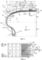
- a reference X, Y, Z is shown corresponding to the usual directions respectively axial (Y), radial (Z) and circumferential (X) of a tire.
- the tire 10 has a substantially toric shape around an axis of revolution substantially parallel to the axial direction Y.
- the tire 10 is intended for a passenger vehicle and has dimensions 225/45 R17. In the various figures, the tire 10 is shown in new condition, that is to say not having yet been driven.
- the tire 10 comprises a crown 12 comprising a tread 14 intended to come into contact with a ground when rolling and a crown reinforcement 16 extending in the crown 12 in the circumferential direction X.
- the tire 10 also comprises a sealing layer 18 to an inflation gas being intended to delimit an internal cavity closed with a mounting support of the tire 10 once the tire 10 is mounted on the mounting support, for example a rim.
- the crown reinforcement 16 comprises a working reinforcement 20 and a hoop reinforcement 22.
- the working reinforcement 16 comprises at least one working layer and here comprises two working layers 24, 26.
- the working reinforcement 16 is made up of the two working layers 24, 26.
- the radially inner working layer 24 is arranged radially inside the radially outer working layer 26.
- the hoop reinforcement 22 comprises at least one hoop layer and here comprises a hoop layer 28.
- the hoop reinforcement 22 here consists of the hoop layer 28.
- the crown reinforcement 16 is radially surmounted by the tread 14.
- the hoop reinforcement 22, here the hoop layer 28, is arranged radially outside the working reinforcement 20 and is therefore radially intercalated between the working reinforcement 20 and the tread 14.
- the hoop reinforcement 22 has an axial width at least as great as the axial width of the working reinforcement 20 and, in this case, in the embodiment illustrated in FIG. figure 1 , the hooping frame 22 has an axial width greater than the axial width of the working frame 20.
- the tire 10 comprises two sidewalls 30 extending the crown 12 radially inwards.
- the tire 10 further comprises two beads 32 radially inwards to the sidewalls 30.
- Each sidewall 30 connects each bead 32 to the crown 12.
- the tire 10 comprises a carcass reinforcement 34 anchored in each bead 32, in this case is wound around a bead wire 33.
- the carcass reinforcement 34 extends in each sidewall 30 and radially internally to the crown 12.
- the crown reinforcement 16 is arranged radially between the tread 14 and the carcass reinforcement 34.
- the carcass reinforcement 34 comprises at least one carcass layer and here comprises a single carcass layer 36. In this case, the carcass reinforcement 34 is made up of the single carcass layer 36.
- Each working layer 24, 26 of hooping 28 and carcass 36 comprises an elastomeric matrix in which one or more wire reinforcement elements of the corresponding layer are embedded.
- the hoop reinforcement 22, here the hoop layer 28, is delimited axially by two axial edges 28A, 28B of the hoop reinforcement 22.
- the hoop reinforcement 22 comprises one or more hoop wire reinforcement elements 280 wound circumferentially helically so as to extend axially from the axial edge 28A to the other axial edge 28B of the hoop layer 28 in a main direction D0 of each hoop wire reinforcement element 280.
- the main direction D0 forms, with the circumferential direction X of the tire 10, an angle AF, in absolute value, less than or equal to 10°, preferably less than or equal to 7° and more preferably less than or equal to 5°.
- AF -5°.
- the hoop layer 28 comprises a density of 98 hoop wire reinforcement elements per decimeter of hoop layer, this density being measured perpendicular to the direction D0.
- the radially inner working layer 24 is axially delimited by two axial edges 24A, 24B.
- the radially inner working layer 24 comprises working wire reinforcement elements 240 extending axially from the axial edge 24A to the other axial edge 24B, each substantially parallel to the other in a main direction D1.
- the radially outer working layer 26 is axially delimited by two axial edges 26A, 26B.
- the radially outer working layer 26 comprises working wire reinforcement elements 260 extending axially from the axial edge 26A to the other axial edge 26B, each substantially parallel to the other in a main direction D2.
- the main direction D1 along which each working wire reinforcement element 240 of the radially inner working layer 24 extends and the main direction D2 along which each working wire reinforcement element 260 of the other of the radially outer working layer 26 extends form, with the circumferential direction X of the tire 10, angles AT1 and AT2 respectively of opposite orientations.
- Each main direction D1, D2 forms, with the circumferential direction X of the tire 10, an angle AT1, AT2 respectively, in absolute value, strictly greater than 10°, preferably ranging from 15° to 50° and more preferably ranging from 15° to 30°.
- the carcass layer 36 is delimited axially by two axial edges 36A, 36B.
- Each hoop wire reinforcement element 280 conventionally comprises two multifilament strands, each multifilament strand being made up of a yarn of aliphatic polyamide monofilaments, here nylon with a count equal to 140 tex, these two multifilament strands being individually helical at 250 turns per meter in one direction and then helical together at 250 turns per meter in the opposite direction. These two multifilament strands are helically wound around each other.
- a hooping wire reinforcement element 280 may be used comprising a multifilament strand consisting of a yarn of aliphatic polyamide monofilaments, here nylon with a count equal to 140 tex and a multifilament strand consisting of a yarn of aromatic polyamide monofilaments, here aramid with a count equal to 167 tex, these two multifilament strands being individually helical at 290 turns per meter in one direction and then helical together at 290 turns per meter in the opposite direction. These two multifilament strands are helical wound around each other.
- Each working wire reinforcement element 180 is an assembly of two steel monofilaments wound in a helix at a pitch of 1.2 or 1.05 mm, each steel monofilament having a diameter equal to 0.30 mm. In another variant, each working wire reinforcement element 180 is made of a steel monofilament having a diameter equal to 0.30 mm. More generally, the steel monofilaments have diameters ranging from 0.25 mm to 0.32 mm.
- Each 340 carcass wire reinforcement element conventionally comprises two multifilament strands, each multifilament strand being made up of a polyester monofilament yarn, here PET, these two multifilament strands being individually helical at 240 turns per meter in one direction and then helical together at 240 turns per meter in the opposite direction.
- Each of these multifilament strands has a count equal to 220 tex. In other variants, counts equal to 144 tex or 334 tex may be used.
- the tread 14 comprises a tread surface 38 through which the tread 14 contacts the ground.
- the tread 14 also comprises cutouts 40 and tread blocks 42, the cutouts 40 separating the tread blocks 42 from each other.
- the cutouts 40 comprise several circumferential grooves 44, at least one of which forms the deepest cutout of the tire 10.
- the rolling surface 38 is intended to come into contact with the ground when the tire 10 is rolling on the ground and is delimited axially by two axial limits 39 passing through each point N arranged on either side of the median plane M and for which the angle between the tangent T to the rolling surface 38 and a straight line R parallel to the axial direction Y passing through this point is equal to 30°.
- the tread 14 here comprises an axially central portion P1 comprising the median plane of the tire 10 and here axially centered on the median plane M of the tire 10.
- the tread 14 also includes several regulatory wear indicators 46 defining a regulatory wear threshold below which the tire no longer complies with the corresponding regulations in terms of wear.
- the wear indicator 46 illustrated in the figures 1 And 3 to 6 is arranged at the bottom 48 of the deepest cutout, here at the bottom 48 of one of the circumferential grooves 44.
- the regulatory wear indicator 46 is formed by a protuberance 50 extending radially from the bottom 48 of the circumferential groove 44 radially outwards over a radial height HT ranging from 1.45 mm to 1.75 mm and here substantially equal to 1.6 mm.
- the regulatory wear indicator 46 has a most radially external point here formed by the radially external surface 51 of the regulatory wear indicator 46.
- the surface notch rate of the tire ranges from 20% to 35%, preferably from 22% to 30% and is here equal to 25%.
- the tread 14 comprises a tread layer 52 carrying the tread surface 38 as well as a support layer 54 of the tread layer 52 arranged radially inside the tread layer 52.
- a support layer 54 is generally called an underlayer.
- the axial width J of the support layer 54 is greater than or equal to 90% of the axial width L of the tread surface 38 and here the axial width J of the support layer 54 is greater than or equal to 100% of the axial width L of the tread surface 38 and here equal to 105% of the axial width L of the tread surface 38.
- the wearing course 52 and the support course 54 are joined by through an interface 56 describing, in the meridian section plane of the figure 3 comprising the regulatory wear indicator 46, an interface trajectory 58.
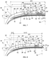
- the interface path 58 has a length l located radially perpendicular to the tread blocks 42, the length l being equal to the sum of the lengths l1, l2, l3 located radially perpendicular to the tread blocks 42, the remainder of the length of the interface path 58 being equal to the sum of the lengths U1 and U2 located radially perpendicular to the cutouts 40, here radially perpendicular to the circumferential grooves 44.
- all of the lengths l1, l2, l3 located radially above the tread blocks 42 are located radially inside the regulatory wear path 60 so that 100% of the length l of the interface path 58 located radially above the tread blocks 42 is arranged in the meridian section plane of the figure 3 , radially inside the regulatory wear path 60.
- the lengths K1 ⁇ l1, K2 ⁇ l2, K3 ⁇ l3 correspond to the lengths of the interface path 58 located at an average radial distance d1 less than or equal to 1.0 mm from the regulatory wear path 60.
- K1 2.85 cm
- K2 2.18 cm
- K3 1.09 cm so that 97% of the length I is arranged, in the meridian cutting plane of the figure 4 , at an average radial distance d1 less than or equal to 1.0 mm from the regulatory wear path 60.
- all of the lengths l1, l2, l3 located radially perpendicular to the tread blocks 42 are arranged at an average radial distance d1 greater than or equal to 0.6 mm from the regulatory wear path 60 so that 100% of the length l is arranged, in the meridian section plane of the figure 4 , at an average radial distance d1 greater than or equal to 0.6 mm from the regulatory wear path 60.
- the radial distance between the regulatory wear path 60 and the entire length l of the interface path 58 located radially above the tread blocks 42 varies between 0.8 mm and 2.65 mm. If we limit our to the lengths K1, K2, K3 located radially above the tread blocks 42, 97% of the length l of the interface path 58 located radially above the tread blocks 42 is arranged, in the meridian section plane of the figure 4 , at a radial distance between 0.6 mm and 1.0 mm from the regulatory wear path 60 corresponding to an average radial distance d1 equal to 0.85 mm.
- the lengths F1, F2, F3 such that K1 ⁇ F1 ⁇ l1, K2 ⁇ F2 ⁇ l2, K3 ⁇ F3 ⁇ l3 correspond to the lengths of the interface trajectory 58 arranged radially outside the trajectory 62.
- F1 2.86 cm
- F2 2.20 cm
- F3 1.10 cm so that 97% of the length l of the interface trajectory 58 located radially perpendicular to the tread blocks 42 is arranged in half of the axially central portion P1 of the tread strip. bearing 14, in the meridian section plane of the figure 5 , radially outside the trajectory 62.
- the axial portion of the tread 14 located radially perpendicular to the deepest cutout, here located radially perpendicular to each circumferential groove 44 comprises a non-zero radial thickness E1 of the tread layer 52 and a non-zero radial thickness E2 of the support layer 54.
- the ratio E1/E2 varies between 0.40 and 0.60 and is here substantially equal to 0.50.
- the rolling layer 52 comprises a rolling elastomeric material M1 and the support layer 54 comprises a support elastomeric material M2 different from the rolling elastomeric material.
- the rolling elastomeric material is based on the composition CD1 described in WO2018115722 whereas the elastomeric support material is based on the composition CC1 described in WO2018115722 .
- Other compositions can of course be used by varying the levels of the different constituents of the compositions in order to obtain properties adapted to particular uses, without departing from the scope of the invention.
- the volume of the rolling elastomeric material M1 in the central portion P1 is greater than or equal to 60%, preferably greater than or equal to 65% and here equal to 70% of the volume of the central portion P1.
- the volume of the supporting elastomeric material M2 in the central portion P1 is less than or equal to 40%, preferably less than or equal to 35% of the volume of the central portion P1 and here equal to 30%.
- G*_2 ⁇ 0.90 x G*_1 and even that G*_2 ⁇ 0.92 x G*_1, and even G*_2 ⁇ G*_1 and here G*_2>G*_1.
- tanD0_2 ⁇ 0.37 x tanD0_1 and even that tanD0_2 ⁇ 0.5 tanD0_1, preferably tanD0_2 ⁇ 0.75 x tanD0_1. It will be noted that in other very advantageous embodiments in which the elastomeric support material M2 is modified so as to increase tanD0_2, it is preferentially tanD0_2 ⁇ tanD0_1 and very advantageously tanD0_2 > tanD0_1 and even tanD0_2 ⁇ 1.10 x tanD0_1. In order to increase the value of tanD0_2, it will be possible to increase, as is known to those skilled in the art, the glass transition temperature of the elastomeric support material and/or its silica content.
- the rolling elastomeric material M1 has a dynamic loss tanDMAX23_1 measured according to the ASTM D-5992-96 standard, at a temperature of 23°C and at a frequency of 10Hz, ranging from 0.13 to 0.70 and preferably from 0.13 to 0.47 and here equal to 0.25.
- the support elastomeric material M2 has a dynamic loss tanDMAX23_2 measured according to the ASTM D-5992-96 standard, at a temperature of 23°C and at a frequency of 10Hz, ranging from 0.13 to 0.53 and preferably from 0.13 to 0.46 and here equal to 0.31.
- the tire according to the second embodiment of the figure 7 presents, in the axially central portion P1 of the tread 14, rises of the support layer 54 near the cutouts 40, here the circumferential grooves 44, directly above each sculpture block 42.
- the tire according to the second embodiment of the figure 7 presents, in the axially central portion P1 of the tread 14, rises of the support layer 54 near the cutouts 40, here the circumferential grooves 44, directly above each sculpture block 42.
- at least one non-zero length l' of the interface trajectory 58 located directly above the radial sculpture blocks 42 is arranged, in the meridian section plane of the figure 7 , radially outside the regulatory wear path 60.
- the axially central portion P1 of the tread 14 has an axial width L1 strictly less than the axial width L of the tread surface 38 so that the tread 14 comprises axially lateral portions P2 arranged axially outside the axially central portion P1.
- the rolling layer 52 of each axially lateral portion P2 comprises an elastomeric material different from the elastomeric material of the axially central portion P1.
- an elastomeric material having a relatively low rolling resistance will be chosen, for example as described in WO2014/090845 .
- each tire was planed until reaching a tread height equal to 2 mm to simulate a use of more than half and here 93% of its wear potential.
- the tread height is defined as being the radial height between the radially innermost point of the deepest cut(s) and its projection on the ground when the tire is rolling. This tread height is such that the regulatory wear trajectory is not reached, the latter corresponding to a tread height equal to 1.6 mm and is representative of an advanced state of wear of the tire, in this case beyond half of its wear potential (here 93% of the wear potential has been consumed).
- the planing was carried out in a manner known to those skilled in the art on a rolling machine equipped with a planing head in contact with which the tire is rolled under rolling conditions representative of normal rolling conditions.
Landscapes
- Engineering & Computer Science (AREA)
- Mechanical Engineering (AREA)
- Tires In General (AREA)
Claims (15)
- Reifen (10) für ein Personenfahrzeug, beinhaltend einen Laufstreifen (14), der Ausschnitte (40) und Profilblöcke (42) beinhaltet, wobei die Ausschnitte (40) die Profilblöcke (42) voneinander trennen, wobei der Laufstreifen (14) dazu bestimmt ist, beim Rollen des Reifens (10) mittels einer Laufoberfläche (38) mit dem Boden in Kontakt zu kommen, wobei der Laufstreifen (14) mindestens einen vorschriftsmäßigen Verschleißanzeiger (46) beinhaltet, der eine vorschriftsmäßige Verschleißschwelle definiert, undwobei in einem axial mittleren Abschnitt (P1) des Laufstreifens (14), der eine axiale Breite (L1) von mindestens 70 % der Breite (L) der Laufoberfläche (38) aufweist, der Laufstreifen (14) Folgendes beinhaltet:- eine Laufschicht (52), die die Laufoberfläche (38) trägt, wobei die Laufschicht (52) ein elastomeres Laufmaterial beinhaltet, das Folgendes aufweist:- einen komplexen dynamischen Schubmodul G*_1, gemessen bei 10 % Verformung gemäß der Norm ASTM D-5992-96, bei einer Temperatur von 23 °C und einer Frequenz von 10 Hz und- einen dynamischen Verlustfaktor tanD0_1, gemessen gemäß der Norm ASTM D-5992-96, bei einer Temperatur von 0 °C und einer Frequenz von 10 Hz,- eine Stützschicht (54) für die Laufschicht (52), die zu der Laufschicht (52) radial innenliegend angeordnet ist, wobei die Stützschicht (54) eine elastomeres Stützmaterial beinhaltet, das Folgendes aufweist:- einen komplexen dynamischen Schubmodul G*_2, gemessen bei 10 % Verformung gemäß der Norm ASTM D-5992-96, bei einer Temperatur von 23 °C und einer Frequenz von 10 Hz und- einen dynamischen Verlustfaktor tanD0_2, gemessen gemäß der Norm ASTM D-5992-96, bei einer Temperatur von 0 °C und einer Frequenz von 10 Hz,wobei sich das elastomere Laufmaterial und das elastomere Stützmaterial voneinander unterscheiden, sodass die Laufschicht (52) und die Stützschicht (54) mittels einer Grenzfläche (56) aneinander grenzen, welche in einer Meridianschnittebene, die den vorschriftsmäßigen Verschleißanzeiger (46) beinhaltet, einen Grenzflächenverlauf (58) beschreibt,wobei in dem axial mittleren Abschnitt (P1) des Laufstreifens (14),wenn man in der Meridianschnittebene einen vorschriftsmäßigen Verschleißverlauf (60) definiert, der zu der Laufoberfläche (38) des Reifens (10) im Neuzustand parallel ist und durch den radial am weitesten außenliegenden Punkt (51) des vorschriftsmäßigen Verschleißanzeigers (46) verläuft, mindestens 75 % der Länge (I) des Grenzflächenverlaufs (58), der sich radial direkt unter den Profilblöcken (42) befindet, in der Meridianschnittebene zu dem vorschriftsmäßigen Verschleißverlauf (60) radial innenliegend angeordnet ist undwobei in dem axial mittleren Abschnitt (P1) des Laufstreifens (14) mindestens 75 % der Länge (I) des Grenzflächenverlaufs (58), der sich radial direkt unter den Profilblöcken (42) befindet, in der Meridianschnittebene mit einem mittleren radialen Abstand (d1) kleiner als oder gleich 2,0 mm zu dem vorschriftsmäßigen Verschleißverlauf (60) angeordnet ist, dadurch gekennzeichnet, dass tanD0_2 ≥ 0,37 x tanD0_1 und G*_2 ≥ 0,90 x G*_1.
- Reifen (10) nach dem vorhergehenden Anspruch, wobei tanD0_2 ≥ 0,5 x tanD0_1, vorzugsweise tanD0_2 ≥ 0,75 x tanD0_1, bevorzugter tanD0_2 ≥ tanD0_1, noch bevorzugter tanD0_2 > tanD0_1 und sogar noch bevorzugter tanD0_2 ≥ 1,10 x tanD0_1.
- Reifen (10) nach einem beliebigen der vorhergehenden Ansprüche, wobei G*_2 ≥ 0,92 x G*_1, vorzugsweise G*_2 ≥ G*_1 und bevorzugter G*_2 > G*_1.
- Reifen (10) nach einem beliebigen der vorhergehenden Ansprüche, wobei in dem axial mittleren Abschnitt (P1) des Laufstreifens (14) mindestens 75 % der Länge (I) des Grenzflächenverlaufs (58), der sich radial direkt unter den Profilblöcken (42) befindet, in der Meridianschnittebene zu einem Verlauf (62), der zu der Laufoberfläche (38) des Reifens (10) im Neuzustand parallel ist und durch den radial am weitesten innenliegenden Punkt (48) des oder jedes tiefsten Ausschnitts (44) verläuft, radial außenliegend angeordnet ist.
- Reifen (10) nach einem beliebigen der vorhergehenden Ansprüche, wobei in dem axial mittleren Abschnitt (P1) des Laufstreifens (14) mindestens 75 % der Länge (I) des Grenzflächenverlaufs (58), der sich radial direkt unter den Profilblöcken (42) befindet, in der Meridianschnittebene mit einem mittleren radialen Abstand (d1) größer als oder gleich 0,4 mm, vorzugsweise größer als oder gleich 0,6 mm, zu dem vorschriftsmäßigen Verschleißverlauf (60) angeordnet ist.
- Reifen (10) nach einem beliebigen der vorhergehenden Ansprüche, wobei in dem axial mittleren Abschnitt (P1) des Laufstreifens (14) mindestens eine Länge (I') ungleich null des Grenzflächenverlaufs (58), der sich radial direkt unter den Profilblöcken (42) befindet, in der Meridianschnittebene zu dem vorschriftsmäßigen Verschleißverlauf (60) radial außenliegend angeordnet ist.
- Reifen (10) nach einem beliebigen der vorhergehenden Ansprüche, wobei tanD0_1 von 0,50 bis 1,00 reicht und bevorzugter von 0,50 bis 0,85 reicht.
- Reifen (10) nach einem beliebigen der vorhergehenden Ansprüche, wobei tanD0_2 von 0,60 bis 1,10 reicht und bevorzugter von 0,60 bis 1,00 reicht.
- Reifen (10) nach einem beliebigen der vorhergehenden Ansprüche, wobei G*_1 von 1,30 MPa bis 4,10 MPa reicht und bevorzugter von 1,30 MPa bis 3,00 MPa reicht.
- Reifen (10) nach einem beliebigen der vorhergehenden Ansprüche, wobei G*_2 größer als oder gleich 2,00 MPa ist, vorzugsweise von 2,00 bis 4,10 MPa reicht und bevorzugter von 2,15 bis 3,50 MPa reicht.
- Reifen (10) nach einem beliebigen der vorhergehenden Ansprüche, der einen Gürtel (12) beinhaltet, der eine Gürtelbewehrung (16) beinhaltet, die zu dem Laufstreifen (14) radial innenliegend angeordnet ist, und wobei in dem axial mittleren Abschnitt (P1) des Laufstreifens (14) der mittlere Abstand (d2) zwischen der radial am weitesten außenliegenden Schicht (28) der Gürtelbewehrung (16), die Verstärkungselemente (280) beinhaltet, und dem radial am weitesten innenliegenden Punkt (48) des oder jedes tiefsten Ausschnitts (44) kleiner als oder gleich 2,50 mm, vorzugsweise kleiner als oder gleich 2,25 mm ist.
- Reifen (10) nach einem beliebigen der vorhergehenden Ansprüche, der einen Gürtel (12) beinhaltet, der eine Gürtelbewehrung (16) beinhaltet, die zu dem Laufstreifen (14) radial innenliegend angeordnet ist, und wobei in dem axial mittleren Abschnitt (P1) des Laufstreifens (14) der mittlere Abstand (d2) zwischen der radial am weitesten außenliegenden Schicht (28) der Gürtelbewehrung (16), die Verstärkungselemente (280) beinhaltet, und dem radial am weitesten innenliegenden Punkt (48) des oder jedes tiefsten Ausschnitts (44) größer als oder gleich 1,0 mm ist.
- Reifen (10) nach einem beliebigen der vorhergehenden Ansprüche, wobei das elastomere Laufmaterial einen dynamischen Verlustfaktor tanDMAX23_1, gemessen gemäß der Norm ASTM D-5992-96, bei einer Temperatur von 23 °C und einer Frequenz von 10 Hz aufweist, der von 0,13 bis 0,70 und vorzugsweise von 0,13 bis 0,47 reicht.
- Reifen (10) nach einem beliebigen der vorhergehenden Ansprüche, wobei das elastomere Stützmaterial einen dynamischen Verlustfaktor tanDMAX23_2, gemessen gemäß der Norm ASTM D-5992-96, bei einer Temperatur von 23 °C und einer Frequenz von 10 Hz aufweist, der von 0,13 bis 0,53 und vorzugsweise von 0,13 bis 0,46 reicht.
- Reifen (10) nach einem beliebigen der vorhergehenden Ansprüche, wobei der oberflächenbezogene Negativprofilanteil des Reifens (10), der eine Profilhöhe (HS) von 2,0 mm nach Verschleiß aufweist, von 20 % bis 35 %, vorzugsweise von 22 % bis 30 % reicht, wobei der oberflächenbezogene Negativprofilanteil des Reifens das Verhältnis zwischen Folgendem ist:- der Differenz zwischen der Gesamtfläche des Kontaktabdrucks des Laufstreifens des auf Nenndruck aufgepumpten Reifens unter Nennlast bei glattem Rollboden und der Kontaktfläche der Elemente des Laufstreifens mit dem Rollboden und- der Gesamtfläche des Kontaktabdrucks des Laufstreifens des auf Nenndruck aufgepumpten Reifens unter Nennlast bei glattem Rollboden, wobei die Nennlast 80 % der Tragfähigkeit der Norm der European Tyre and Rim Technical Organisation, 2019, beträgt und der Nenndruck 2,5 bar beträgt.
Applications Claiming Priority (2)
| Application Number | Priority Date | Filing Date | Title |
|---|---|---|---|
| FR2004711 | 2020-05-13 | ||
| PCT/FR2021/050698 WO2021229160A1 (fr) | 2020-05-13 | 2021-04-22 | Pneumatique a adherence sur sol mouille amelioree en fin de vie |
Publications (2)
| Publication Number | Publication Date |
|---|---|
| EP4149773A1 EP4149773A1 (de) | 2023-03-22 |
| EP4149773B1 true EP4149773B1 (de) | 2024-10-02 |
Family
ID=72178690
Family Applications (1)
| Application Number | Title | Priority Date | Filing Date |
|---|---|---|---|
| EP21732393.0A Active EP4149773B1 (de) | 2020-05-13 | 2021-04-22 | Reifen mit verbesserter griffigkeit am ende der lebensdauer auf nassem boden |
Country Status (5)
| Country | Link |
|---|---|
| US (1) | US12570109B2 (de) |
| EP (1) | EP4149773B1 (de) |
| JP (1) | JP7696926B2 (de) |
| CN (1) | CN115551722B (de) |
| WO (1) | WO2021229160A1 (de) |
Families Citing this family (4)
| Publication number | Priority date | Publication date | Assignee | Title |
|---|---|---|---|---|
| FR3104067A1 (fr) | 2019-12-04 | 2021-06-11 | Compagnie Generale Des Etablissements Michelin | Pneumatique à bande de roulement perfectionnée |
| EP4219193B1 (de) * | 2022-01-31 | 2025-02-12 | Sumitomo Rubber Industries, Ltd. | Verfahren zur verwendung eines reifens |
| FR3148541A1 (fr) * | 2023-05-12 | 2024-11-15 | Compagnie Generale Des Etablissements Michelin | Pneumatique à bande de roulement molle et à sculpture rigide |
| FR3150471A1 (fr) * | 2023-06-29 | 2025-01-03 | Compagnie Generale Des Etablissements Michelin | Pneumatique présentant une résistance au roulement moins sensible à la température |
Family Cites Families (32)
| Publication number | Priority date | Publication date | Assignee | Title |
|---|---|---|---|---|
| JPS5647305A (en) * | 1979-09-25 | 1981-04-30 | Sumitomo Rubber Ind Ltd | Radial tire for passenger car |
| JPS5667606A (en) * | 1979-11-05 | 1981-06-06 | Sumitomo Rubber Ind Ltd | Radial tire for passenger car |
| JPS6012244B2 (ja) * | 1980-09-09 | 1985-03-30 | 住友ゴム工業株式会社 | 乗用車用スチ−ルベルトラジアルタイヤ |
| JPS63240405A (ja) * | 1987-03-25 | 1988-10-06 | Ohtsu Tire & Rubber Co Ltd | 乗用車用ラジアルタイヤ |
| JP3020182B2 (ja) * | 1991-04-12 | 2000-03-15 | 横浜ゴム株式会社 | 乗用車用空気入りラジアルタイヤ |
| JPH0596651A (ja) * | 1991-10-08 | 1993-04-20 | Bridgestone Corp | 空気入りタイヤ用未加硫トレツド素材および空気入りタイヤの製造方法 |
| JPH05178011A (ja) * | 1991-12-27 | 1993-07-20 | Yokohama Rubber Co Ltd:The | 空気入りラジアルタイヤ |
| JPH05238202A (ja) * | 1992-02-27 | 1993-09-17 | Yokohama Rubber Co Ltd:The | 乗用車用空気入りラジアルタイヤ |
| JPH06297911A (ja) * | 1993-04-14 | 1994-10-25 | Toyo Tire & Rubber Co Ltd | タイヤ |
| US5580404A (en) * | 1993-08-30 | 1996-12-03 | The Goodyear Tire & Rubber Company | Tread including tie bars and sipes |
| JP3562772B2 (ja) * | 1994-10-04 | 2004-09-08 | 東洋ゴム工業株式会社 | 空気入りタイヤ |
| JPH1076809A (ja) * | 1996-07-11 | 1998-03-24 | Bridgestone Corp | 空気入りタイヤ |
| JP2000185520A (ja) | 1998-12-24 | 2000-07-04 | Bridgestone Corp | 空気入りタイヤ |
| JP3308252B2 (ja) * | 1999-12-14 | 2002-07-29 | 住友ゴム工業株式会社 | 空気入りタイヤ |
| US6626216B2 (en) * | 2000-06-29 | 2003-09-30 | Nokia Corporation | Pneumatic tire having hollow particles in base rubber |
| JP4044526B2 (ja) * | 2004-01-27 | 2008-02-06 | 住友ゴム工業株式会社 | 空気入りタイヤとリムとの組立体 |
| JP2006088585A (ja) * | 2004-09-24 | 2006-04-06 | Bridgestone Corp | 空気入りタイヤ、空気入りタイヤの製造方法及び空気入りタイヤの加硫成形用金型 |
| DE102006015000A1 (de) | 2005-04-15 | 2006-10-26 | The Goodyear Tire & Rubber Co., Akron | Reifen, insbesondere Lastwagenrennreifen |
| JP2009525277A (ja) * | 2006-01-30 | 2009-07-09 | グロボアジア エルエルシー | 軟組織石灰化の回復、予防、遅延または安定化方法 |
| US20090255613A1 (en) * | 2008-04-09 | 2009-10-15 | Ping Zhang | Tire with tread having an intermediate rubber layer containing a microsphere dispersion |
| JP5461043B2 (ja) * | 2009-03-30 | 2014-04-02 | 東洋ゴム工業株式会社 | タイヤ加硫用金型および空気入りタイヤ |
| FR2952855B1 (fr) * | 2009-11-26 | 2011-11-11 | Michelin Soc Tech | Pneu destine a equiper un vehicule portant de lourdes charges |
| JP2012254768A (ja) | 2011-06-10 | 2012-12-27 | Bridgestone Corp | 乗用車用空気入りタイヤ |
| FR2982529B1 (fr) | 2011-11-15 | 2014-01-03 | Michelin Soc Tech | Pneumatique cloute perfectionne. |
| FR2983122B1 (fr) * | 2011-11-29 | 2014-01-03 | Michelin Soc Tech | Pneumatique comportant une bande de roulement constituee de plusieurs melanges elastomeriques |
| FR2999473B1 (fr) | 2012-12-14 | 2015-03-20 | Michelin & Cie | Pneumatique ayant une basse resistance au roulement |
| JP6174921B2 (ja) * | 2013-06-19 | 2017-08-02 | 住友ゴム工業株式会社 | タイヤ |
| FR3022847B1 (fr) * | 2014-06-26 | 2016-06-10 | Michelin & Cie | Pneumatique comportant une couche d'elements de renforcement circonferentiels |
| JP6758088B2 (ja) * | 2016-05-20 | 2020-09-23 | 株式会社ブリヂストン | 空気入りタイヤ |
| WO2018115722A1 (fr) | 2016-12-20 | 2018-06-28 | Compagnie Generale Des Etablissements Michelin | Composition de caoutchouc comprenant un élastomère diénique modifié |
| US11731460B2 (en) | 2017-09-28 | 2023-08-22 | Compagnie Generale Des Etablissements Michelin | Truck tire having tread design with alternating feature for reducing abnormal wear |
| JP2025051504A (ja) * | 2023-09-25 | 2025-04-04 | ソフトバンクグループ株式会社 | システム |
-
2021
- 2021-04-22 WO PCT/FR2021/050698 patent/WO2021229160A1/fr not_active Ceased
- 2021-04-22 CN CN202180034373.9A patent/CN115551722B/zh active Active
- 2021-04-22 JP JP2022568861A patent/JP7696926B2/ja active Active
- 2021-04-22 US US17/924,600 patent/US12570109B2/en active Active
- 2021-04-22 EP EP21732393.0A patent/EP4149773B1/de active Active
Also Published As
| Publication number | Publication date |
|---|---|
| JP2023525132A (ja) | 2023-06-14 |
| JP7696926B2 (ja) | 2025-06-23 |
| EP4149773A1 (de) | 2023-03-22 |
| US12570109B2 (en) | 2026-03-10 |
| US20230191851A1 (en) | 2023-06-22 |
| CN115551722B (zh) | 2025-11-11 |
| WO2021229160A1 (fr) | 2021-11-18 |
| CN115551722A (zh) | 2022-12-30 |
Similar Documents
| Publication | Publication Date | Title |
|---|---|---|
| EP4149773B1 (de) | Reifen mit verbesserter griffigkeit am ende der lebensdauer auf nassem boden | |
| EP4164898B1 (de) | Geräuscharmer reifen | |
| EP3310589B1 (de) | Luftreifen mit einer krone mit verstärkungslage und lauffläche mit hoher bodenhaftung | |
| EP1264713B1 (de) | Lauffläche mit neigungsvariablen Feineinschnitten enthaltenden Rippen | |
| EP3310591B1 (de) | Luftreifen mit einem deckenbereich mit einem verstärkungselement und einer lauffläche mit hoher bodenhaftung | |
| EP3946973B1 (de) | Reifen mit arbeitsschichten mit optimierter architektur und laufflächengestaltung | |
| WO2017103431A1 (fr) | Pneumatique présentant des propriétés d'usure améliore | |
| EP4222003B1 (de) | Reifen mit einer optimierten schicht aus selbstdichtendem produkt | |
| EP4526133A1 (de) | Reifen mit einer nachschneidenden lauffläche | |
| EP4221967B1 (de) | Verfahren zur herstellung einer optimierten schicht eines selbstdichtenden produkts | |
| EP4228905B1 (de) | Reifen mit einer lauffläche aus mehreren elastomerverbindungen | |
| EP4259456B1 (de) | Reifen mit einer lauffläche mit mindestens einer schicht aus textilen verstärkungselementen | |
| FR3150990A1 (fr) | Pneumatique comportant une bande de roulement recreusable | |
| EP3621825B1 (de) | Reifen mit optimierter architektur und lauffläche | |
| FR3159556A1 (fr) | Pneumatique comprenant une bande de roulement complexe résistante à l’usure | |
| FR3154036A1 (fr) | Pneumatique comportant une bande de roulement recreusable | |
| FR3159557A1 (fr) | Pneumatique comprenant une bande de roulement complexe à interface endurante | |
| FR3161387A1 (fr) | Pneumatique comprenant un sous-creux réduit et une bande de roulement silencieuse | |
| FR3037530A1 (fr) | Pneumatique avec un sommet comportant une nappe de renforcement et une bande de roulement a forte adherence | |
| WO2024235645A1 (fr) | Pneumatique à bande de roulement molle et à sculpture rigide | |
| WO2020128209A1 (fr) | Pneumatique pour camionnette optimise | |
| EP3898271A1 (de) | Optimierter fahrzeugreifen für einen kleintransporter | |
| FR3042440A3 (fr) | Pneumatique avec un sommet comportant une nappe de rigidification et une bande de roulement a forte adherence |
Legal Events
| Date | Code | Title | Description |
|---|---|---|---|
| STAA | Information on the status of an ep patent application or granted ep patent |
Free format text: STATUS: UNKNOWN |
|
| STAA | Information on the status of an ep patent application or granted ep patent |
Free format text: STATUS: THE INTERNATIONAL PUBLICATION HAS BEEN MADE |
|
| PUAI | Public reference made under article 153(3) epc to a published international application that has entered the european phase |
Free format text: ORIGINAL CODE: 0009012 |
|
| STAA | Information on the status of an ep patent application or granted ep patent |
Free format text: STATUS: REQUEST FOR EXAMINATION WAS MADE |
|
| 17P | Request for examination filed |
Effective date: 20221213 |
|
| AK | Designated contracting states |
Kind code of ref document: A1 Designated state(s): AL AT BE BG CH CY CZ DE DK EE ES FI FR GB GR HR HU IE IS IT LI LT LU LV MC MK MT NL NO PL PT RO RS SE SI SK SM TR |
|
| DAV | Request for validation of the european patent (deleted) | ||
| DAX | Request for extension of the european patent (deleted) | ||
| GRAP | Despatch of communication of intention to grant a patent |
Free format text: ORIGINAL CODE: EPIDOSNIGR1 |
|
| STAA | Information on the status of an ep patent application or granted ep patent |
Free format text: STATUS: GRANT OF PATENT IS INTENDED |
|
| INTG | Intention to grant announced |
Effective date: 20240618 |
|
| GRAS | Grant fee paid |
Free format text: ORIGINAL CODE: EPIDOSNIGR3 |
|
| GRAA | (expected) grant |
Free format text: ORIGINAL CODE: 0009210 |
|
| STAA | Information on the status of an ep patent application or granted ep patent |
Free format text: STATUS: THE PATENT HAS BEEN GRANTED |
|
| AK | Designated contracting states |
Kind code of ref document: B1 Designated state(s): AL AT BE BG CH CY CZ DE DK EE ES FI FR GB GR HR HU IE IS IT LI LT LU LV MC MK MT NL NO PL PT RO RS SE SI SK SM TR |
|
| REG | Reference to a national code |
Ref country code: GB Ref legal event code: FG4D Free format text: NOT ENGLISH |
|
| REG | Reference to a national code |
Ref country code: CH Ref legal event code: EP |
|
| REG | Reference to a national code |
Ref country code: DE Ref legal event code: R096 Ref document number: 602021019604 Country of ref document: DE |
|
| REG | Reference to a national code |
Ref country code: IE Ref legal event code: FG4D Free format text: LANGUAGE OF EP DOCUMENT: FRENCH |
|
| REG | Reference to a national code |
Ref country code: LT Ref legal event code: MG9D |
|
| REG | Reference to a national code |
Ref country code: NL Ref legal event code: MP Effective date: 20241002 |
|
| REG | Reference to a national code |
Ref country code: AT Ref legal event code: MK05 Ref document number: 1728219 Country of ref document: AT Kind code of ref document: T Effective date: 20241002 |
|
| PG25 | Lapsed in a contracting state [announced via postgrant information from national office to epo] |
Ref country code: NL Free format text: LAPSE BECAUSE OF FAILURE TO SUBMIT A TRANSLATION OF THE DESCRIPTION OR TO PAY THE FEE WITHIN THE PRESCRIBED TIME-LIMIT Effective date: 20241002 |
|
| PG25 | Lapsed in a contracting state [announced via postgrant information from national office to epo] |
Ref country code: NL Free format text: LAPSE BECAUSE OF FAILURE TO SUBMIT A TRANSLATION OF THE DESCRIPTION OR TO PAY THE FEE WITHIN THE PRESCRIBED TIME-LIMIT Effective date: 20241002 |
|
| PG25 | Lapsed in a contracting state [announced via postgrant information from national office to epo] |
Ref country code: IS Free format text: LAPSE BECAUSE OF FAILURE TO SUBMIT A TRANSLATION OF THE DESCRIPTION OR TO PAY THE FEE WITHIN THE PRESCRIBED TIME-LIMIT Effective date: 20250202 Ref country code: PT Free format text: LAPSE BECAUSE OF FAILURE TO SUBMIT A TRANSLATION OF THE DESCRIPTION OR TO PAY THE FEE WITHIN THE PRESCRIBED TIME-LIMIT Effective date: 20250203 Ref country code: HR Free format text: LAPSE BECAUSE OF FAILURE TO SUBMIT A TRANSLATION OF THE DESCRIPTION OR TO PAY THE FEE WITHIN THE PRESCRIBED TIME-LIMIT Effective date: 20241002 |
|
| PG25 | Lapsed in a contracting state [announced via postgrant information from national office to epo] |
Ref country code: FI Free format text: LAPSE BECAUSE OF FAILURE TO SUBMIT A TRANSLATION OF THE DESCRIPTION OR TO PAY THE FEE WITHIN THE PRESCRIBED TIME-LIMIT Effective date: 20241002 |
|
| PG25 | Lapsed in a contracting state [announced via postgrant information from national office to epo] |
Ref country code: BG Free format text: LAPSE BECAUSE OF FAILURE TO SUBMIT A TRANSLATION OF THE DESCRIPTION OR TO PAY THE FEE WITHIN THE PRESCRIBED TIME-LIMIT Effective date: 20241002 |
|
| PG25 | Lapsed in a contracting state [announced via postgrant information from national office to epo] |
Ref country code: ES Free format text: LAPSE BECAUSE OF FAILURE TO SUBMIT A TRANSLATION OF THE DESCRIPTION OR TO PAY THE FEE WITHIN THE PRESCRIBED TIME-LIMIT Effective date: 20241002 |
|
| PG25 | Lapsed in a contracting state [announced via postgrant information from national office to epo] |
Ref country code: NO Free format text: LAPSE BECAUSE OF FAILURE TO SUBMIT A TRANSLATION OF THE DESCRIPTION OR TO PAY THE FEE WITHIN THE PRESCRIBED TIME-LIMIT Effective date: 20250102 |
|
| PG25 | Lapsed in a contracting state [announced via postgrant information from national office to epo] |
Ref country code: GR Free format text: LAPSE BECAUSE OF FAILURE TO SUBMIT A TRANSLATION OF THE DESCRIPTION OR TO PAY THE FEE WITHIN THE PRESCRIBED TIME-LIMIT Effective date: 20250103 Ref country code: LV Free format text: LAPSE BECAUSE OF FAILURE TO SUBMIT A TRANSLATION OF THE DESCRIPTION OR TO PAY THE FEE WITHIN THE PRESCRIBED TIME-LIMIT Effective date: 20241002 Ref country code: AT Free format text: LAPSE BECAUSE OF FAILURE TO SUBMIT A TRANSLATION OF THE DESCRIPTION OR TO PAY THE FEE WITHIN THE PRESCRIBED TIME-LIMIT Effective date: 20241002 |
|
| PG25 | Lapsed in a contracting state [announced via postgrant information from national office to epo] |
Ref country code: PL Free format text: LAPSE BECAUSE OF FAILURE TO SUBMIT A TRANSLATION OF THE DESCRIPTION OR TO PAY THE FEE WITHIN THE PRESCRIBED TIME-LIMIT Effective date: 20241002 Ref country code: CZ Free format text: LAPSE BECAUSE OF FAILURE TO SUBMIT A TRANSLATION OF THE DESCRIPTION OR TO PAY THE FEE WITHIN THE PRESCRIBED TIME-LIMIT Effective date: 20241002 |
|
| PG25 | Lapsed in a contracting state [announced via postgrant information from national office to epo] |
Ref country code: RS Free format text: LAPSE BECAUSE OF FAILURE TO SUBMIT A TRANSLATION OF THE DESCRIPTION OR TO PAY THE FEE WITHIN THE PRESCRIBED TIME-LIMIT Effective date: 20250102 |
|
| PG25 | Lapsed in a contracting state [announced via postgrant information from national office to epo] |
Ref country code: SM Free format text: LAPSE BECAUSE OF FAILURE TO SUBMIT A TRANSLATION OF THE DESCRIPTION OR TO PAY THE FEE WITHIN THE PRESCRIBED TIME-LIMIT Effective date: 20241002 |
|
| REG | Reference to a national code |
Ref country code: DE Ref legal event code: R097 Ref document number: 602021019604 Country of ref document: DE |
|
| PGFP | Annual fee paid to national office [announced via postgrant information from national office to epo] |
Ref country code: DE Payment date: 20250422 Year of fee payment: 5 |
|
| PG25 | Lapsed in a contracting state [announced via postgrant information from national office to epo] |
Ref country code: DK Free format text: LAPSE BECAUSE OF FAILURE TO SUBMIT A TRANSLATION OF THE DESCRIPTION OR TO PAY THE FEE WITHIN THE PRESCRIBED TIME-LIMIT Effective date: 20241002 |
|
| PG25 | Lapsed in a contracting state [announced via postgrant information from national office to epo] |
Ref country code: EE Free format text: LAPSE BECAUSE OF FAILURE TO SUBMIT A TRANSLATION OF THE DESCRIPTION OR TO PAY THE FEE WITHIN THE PRESCRIBED TIME-LIMIT Effective date: 20241002 |
|
| PGFP | Annual fee paid to national office [announced via postgrant information from national office to epo] |
Ref country code: FR Payment date: 20250425 Year of fee payment: 5 |
|
| PG25 | Lapsed in a contracting state [announced via postgrant information from national office to epo] |
Ref country code: RO Free format text: LAPSE BECAUSE OF FAILURE TO SUBMIT A TRANSLATION OF THE DESCRIPTION OR TO PAY THE FEE WITHIN THE PRESCRIBED TIME-LIMIT Effective date: 20241002 |
|
| PG25 | Lapsed in a contracting state [announced via postgrant information from national office to epo] |
Ref country code: SK Free format text: LAPSE BECAUSE OF FAILURE TO SUBMIT A TRANSLATION OF THE DESCRIPTION OR TO PAY THE FEE WITHIN THE PRESCRIBED TIME-LIMIT Effective date: 20241002 |
|
| PG25 | Lapsed in a contracting state [announced via postgrant information from national office to epo] |
Ref country code: IT Free format text: LAPSE BECAUSE OF FAILURE TO SUBMIT A TRANSLATION OF THE DESCRIPTION OR TO PAY THE FEE WITHIN THE PRESCRIBED TIME-LIMIT Effective date: 20241002 |
|
| PLBE | No opposition filed within time limit |
Free format text: ORIGINAL CODE: 0009261 |
|
| STAA | Information on the status of an ep patent application or granted ep patent |
Free format text: STATUS: NO OPPOSITION FILED WITHIN TIME LIMIT |
|
| PG25 | Lapsed in a contracting state [announced via postgrant information from national office to epo] |
Ref country code: SE Free format text: LAPSE BECAUSE OF FAILURE TO SUBMIT A TRANSLATION OF THE DESCRIPTION OR TO PAY THE FEE WITHIN THE PRESCRIBED TIME-LIMIT Effective date: 20241002 |
|
| 26N | No opposition filed |
Effective date: 20250703 |
|
| REG | Reference to a national code |
Ref country code: CH Ref legal event code: H13 Free format text: ST27 STATUS EVENT CODE: U-0-0-H10-H13 (AS PROVIDED BY THE NATIONAL OFFICE) Effective date: 20251125 |
|
| PG25 | Lapsed in a contracting state [announced via postgrant information from national office to epo] |
Ref country code: LU Free format text: LAPSE BECAUSE OF NON-PAYMENT OF DUE FEES Effective date: 20250422 |
|
| PG25 | Lapsed in a contracting state [announced via postgrant information from national office to epo] |
Ref country code: MC Free format text: LAPSE BECAUSE OF FAILURE TO SUBMIT A TRANSLATION OF THE DESCRIPTION OR TO PAY THE FEE WITHIN THE PRESCRIBED TIME-LIMIT Effective date: 20241002 |
|
| GBPC | Gb: european patent ceased through non-payment of renewal fee |
Effective date: 20250422 |
|
| REG | Reference to a national code |
Ref country code: BE Ref legal event code: MM Effective date: 20250430 |
|
| PG25 | Lapsed in a contracting state [announced via postgrant information from national office to epo] |
Ref country code: GB Free format text: LAPSE BECAUSE OF NON-PAYMENT OF DUE FEES Effective date: 20250422 |
|
| PG25 | Lapsed in a contracting state [announced via postgrant information from national office to epo] |
Ref country code: BE Free format text: LAPSE BECAUSE OF NON-PAYMENT OF DUE FEES Effective date: 20250430 |
|
| PG25 | Lapsed in a contracting state [announced via postgrant information from national office to epo] |
Ref country code: CH Free format text: LAPSE BECAUSE OF NON-PAYMENT OF DUE FEES Effective date: 20250430 |
|
| PG25 | Lapsed in a contracting state [announced via postgrant information from national office to epo] |
Ref country code: IE Free format text: LAPSE BECAUSE OF NON-PAYMENT OF DUE FEES Effective date: 20250422 |