EP4149790B1 - Ladestation für elektrofahrzeuge - Google Patents
Ladestation für elektrofahrzeuge Download PDFInfo
- Publication number
- EP4149790B1 EP4149790B1 EP21722866.7A EP21722866A EP4149790B1 EP 4149790 B1 EP4149790 B1 EP 4149790B1 EP 21722866 A EP21722866 A EP 21722866A EP 4149790 B1 EP4149790 B1 EP 4149790B1
- Authority
- EP
- European Patent Office
- Prior art keywords
- charging
- processing unit
- central processing
- receiver device
- control signal
- Prior art date
- Legal status (The legal status is an assumption and is not a legal conclusion. Google has not performed a legal analysis and makes no representation as to the accuracy of the status listed.)
- Active
Links
Images
Classifications
-
- B—PERFORMING OPERATIONS; TRANSPORTING
- B60—VEHICLES IN GENERAL
- B60L—PROPULSION OF ELECTRICALLY-PROPELLED VEHICLES; SUPPLYING ELECTRIC POWER FOR AUXILIARY EQUIPMENT OF ELECTRICALLY-PROPELLED VEHICLES; ELECTRODYNAMIC BRAKE SYSTEMS FOR VEHICLES IN GENERAL; MAGNETIC SUSPENSION OR LEVITATION FOR VEHICLES; MONITORING OPERATING VARIABLES OF ELECTRICALLY-PROPELLED VEHICLES; ELECTRIC SAFETY DEVICES FOR ELECTRICALLY-PROPELLED VEHICLES
- B60L53/00—Methods of charging batteries, specially adapted for electric vehicles; Charging stations or on-board charging equipment therefor; Exchange of energy storage elements in electric vehicles
- B60L53/10—Methods of charging batteries, specially adapted for electric vehicles; Charging stations or on-board charging equipment therefor; Exchange of energy storage elements in electric vehicles characterised by the energy transfer between the charging station and the vehicle
- B60L53/14—Conductive energy transfer
-
- B—PERFORMING OPERATIONS; TRANSPORTING
- B60—VEHICLES IN GENERAL
- B60L—PROPULSION OF ELECTRICALLY-PROPELLED VEHICLES; SUPPLYING ELECTRIC POWER FOR AUXILIARY EQUIPMENT OF ELECTRICALLY-PROPELLED VEHICLES; ELECTRODYNAMIC BRAKE SYSTEMS FOR VEHICLES IN GENERAL; MAGNETIC SUSPENSION OR LEVITATION FOR VEHICLES; MONITORING OPERATING VARIABLES OF ELECTRICALLY-PROPELLED VEHICLES; ELECTRIC SAFETY DEVICES FOR ELECTRICALLY-PROPELLED VEHICLES
- B60L53/00—Methods of charging batteries, specially adapted for electric vehicles; Charging stations or on-board charging equipment therefor; Exchange of energy storage elements in electric vehicles
- B60L53/60—Monitoring or controlling charging stations
- B60L53/63—Monitoring or controlling charging stations in response to network capacity
-
- B—PERFORMING OPERATIONS; TRANSPORTING
- B60—VEHICLES IN GENERAL
- B60L—PROPULSION OF ELECTRICALLY-PROPELLED VEHICLES; SUPPLYING ELECTRIC POWER FOR AUXILIARY EQUIPMENT OF ELECTRICALLY-PROPELLED VEHICLES; ELECTRODYNAMIC BRAKE SYSTEMS FOR VEHICLES IN GENERAL; MAGNETIC SUSPENSION OR LEVITATION FOR VEHICLES; MONITORING OPERATING VARIABLES OF ELECTRICALLY-PROPELLED VEHICLES; ELECTRIC SAFETY DEVICES FOR ELECTRICALLY-PROPELLED VEHICLES
- B60L53/00—Methods of charging batteries, specially adapted for electric vehicles; Charging stations or on-board charging equipment therefor; Exchange of energy storage elements in electric vehicles
- B60L53/60—Monitoring or controlling charging stations
- B60L53/66—Data transfer between charging stations and vehicles
-
- H—ELECTRICITY
- H01—ELECTRIC ELEMENTS
- H01M—PROCESSES OR MEANS, e.g. BATTERIES, FOR THE DIRECT CONVERSION OF CHEMICAL ENERGY INTO ELECTRICAL ENERGY
- H01M10/00—Secondary cells; Manufacture thereof
- H01M10/42—Methods or arrangements for servicing or maintenance of secondary cells or secondary half-cells
- H01M10/425—Structural combination with electronic components, e.g. electronic circuits integrated to the outside of the casing
-
- H—ELECTRICITY
- H01—ELECTRIC ELEMENTS
- H01M—PROCESSES OR MEANS, e.g. BATTERIES, FOR THE DIRECT CONVERSION OF CHEMICAL ENERGY INTO ELECTRICAL ENERGY
- H01M10/00—Secondary cells; Manufacture thereof
- H01M10/42—Methods or arrangements for servicing or maintenance of secondary cells or secondary half-cells
- H01M10/44—Methods for charging or discharging
-
- H—ELECTRICITY
- H02—GENERATION; CONVERSION OR DISTRIBUTION OF ELECTRIC POWER
- H02J—ELECTRIC POWER NETWORKS; CIRCUIT ARRANGEMENTS OR SYSTEMS FOR SUPPLYING OR DISTRIBUTING ELECTRIC POWER; SYSTEMS FOR STORING ELECTRIC ENERGY
- H02J1/00—Circuit arrangements for DC mains or DC distribution networks
- H02J1/14—Balancing load and power generation in DC networks
-
- H—ELECTRICITY
- H02—GENERATION; CONVERSION OR DISTRIBUTION OF ELECTRIC POWER
- H02J—ELECTRIC POWER NETWORKS; CIRCUIT ARRANGEMENTS OR SYSTEMS FOR SUPPLYING OR DISTRIBUTING ELECTRIC POWER; SYSTEMS FOR STORING ELECTRIC ENERGY
- H02J7/00—Circuit arrangements for charging or discharging batteries or for supplying loads from batteries
- H02J7/50—Circuit arrangements for charging or discharging batteries or for supplying loads from batteries acting upon multiple batteries simultaneously or sequentially
-
- H—ELECTRICITY
- H02—GENERATION; CONVERSION OR DISTRIBUTION OF ELECTRIC POWER
- H02J—ELECTRIC POWER NETWORKS; CIRCUIT ARRANGEMENTS OR SYSTEMS FOR SUPPLYING OR DISTRIBUTING ELECTRIC POWER; SYSTEMS FOR STORING ELECTRIC ENERGY
- H02J7/00—Circuit arrangements for charging or discharging batteries or for supplying loads from batteries
- H02J7/90—Regulation of charging or discharging current or voltage
- H02J7/933—Regulation of charging or discharging current or voltage the cycle being controlled or terminated in response to electric parameters
-
- H—ELECTRICITY
- H04—ELECTRIC COMMUNICATION TECHNIQUE
- H04B—TRANSMISSION
- H04B3/00—Line transmission systems
- H04B3/54—Systems for transmission via power distribution lines
-
- B—PERFORMING OPERATIONS; TRANSPORTING
- B60—VEHICLES IN GENERAL
- B60Y—INDEXING SCHEME RELATING TO ASPECTS CROSS-CUTTING VEHICLE TECHNOLOGY
- B60Y2200/00—Type of vehicle
- B60Y2200/90—Vehicles comprising electric prime movers
- B60Y2200/91—Electric vehicles
-
- H—ELECTRICITY
- H01—ELECTRIC ELEMENTS
- H01M—PROCESSES OR MEANS, e.g. BATTERIES, FOR THE DIRECT CONVERSION OF CHEMICAL ENERGY INTO ELECTRICAL ENERGY
- H01M10/00—Secondary cells; Manufacture thereof
- H01M10/42—Methods or arrangements for servicing or maintenance of secondary cells or secondary half-cells
- H01M10/425—Structural combination with electronic components, e.g. electronic circuits integrated to the outside of the casing
- H01M2010/4278—Systems for data transfer from batteries, e.g. transfer of battery parameters to a controller, data transferred between battery controller and main controller
-
- H—ELECTRICITY
- H01—ELECTRIC ELEMENTS
- H01M—PROCESSES OR MEANS, e.g. BATTERIES, FOR THE DIRECT CONVERSION OF CHEMICAL ENERGY INTO ELECTRICAL ENERGY
- H01M2220/00—Batteries for particular applications
- H01M2220/20—Batteries in motive systems, e.g. vehicle, ship, plane
-
- H—ELECTRICITY
- H02—GENERATION; CONVERSION OR DISTRIBUTION OF ELECTRIC POWER
- H02J—ELECTRIC POWER NETWORKS; CIRCUIT ARRANGEMENTS OR SYSTEMS FOR SUPPLYING OR DISTRIBUTING ELECTRIC POWER; SYSTEMS FOR STORING ELECTRIC ENERGY
- H02J2105/00—Networks for supplying or distributing electric power characterised by their spatial reach or by the load
- H02J2105/30—Networks for supplying or distributing electric power characterised by their spatial reach or by the load the load networks being external to vehicles, i.e. exchanging power with vehicles
- H02J2105/33—Networks for supplying or distributing electric power characterised by their spatial reach or by the load the load networks being external to vehicles, i.e. exchanging power with vehicles exchanging power with road vehicles
- H02J2105/37—Networks for supplying or distributing electric power characterised by their spatial reach or by the load the load networks being external to vehicles, i.e. exchanging power with vehicles exchanging power with road vehicles exchanging power with electric vehicles [EV] or with hybrid electric vehicles [HEV]
-
- H—ELECTRICITY
- H02—GENERATION; CONVERSION OR DISTRIBUTION OF ELECTRIC POWER
- H02J—ELECTRIC POWER NETWORKS; CIRCUIT ARRANGEMENTS OR SYSTEMS FOR SUPPLYING OR DISTRIBUTING ELECTRIC POWER; SYSTEMS FOR STORING ELECTRIC ENERGY
- H02J2105/00—Networks for supplying or distributing electric power characterised by their spatial reach or by the load
- H02J2105/50—Networks for supplying or distributing electric power characterised by their spatial reach or by the load for selectively controlling the operation of the loads
- H02J2105/52—Networks for supplying or distributing electric power characterised by their spatial reach or by the load for selectively controlling the operation of the loads for limitation of the power consumption in the networks or in one section of the networks, e.g. load shedding or peak shaving
-
- H—ELECTRICITY
- H02—GENERATION; CONVERSION OR DISTRIBUTION OF ELECTRIC POWER
- H02J—ELECTRIC POWER NETWORKS; CIRCUIT ARRANGEMENTS OR SYSTEMS FOR SUPPLYING OR DISTRIBUTING ELECTRIC POWER; SYSTEMS FOR STORING ELECTRIC ENERGY
- H02J2105/00—Networks for supplying or distributing electric power characterised by their spatial reach or by the load
- H02J2105/50—Networks for supplying or distributing electric power characterised by their spatial reach or by the load for selectively controlling the operation of the loads
- H02J2105/52—Networks for supplying or distributing electric power characterised by their spatial reach or by the load for selectively controlling the operation of the loads for limitation of the power consumption in the networks or in one section of the networks, e.g. load shedding or peak shaving
- H02J2105/53—Networks for supplying or distributing electric power characterised by their spatial reach or by the load for selectively controlling the operation of the loads for limitation of the power consumption in the networks or in one section of the networks, e.g. load shedding or peak shaving for partial power limitation, e.g. entering degraded or current limitation modes
-
- H—ELECTRICITY
- H04—ELECTRIC COMMUNICATION TECHNIQUE
- H04L—TRANSMISSION OF DIGITAL INFORMATION, e.g. TELEGRAPHIC COMMUNICATION
- H04L12/00—Data switching networks
- H04L12/02—Details
- H04L12/10—Current supply arrangements
-
- Y—GENERAL TAGGING OF NEW TECHNOLOGICAL DEVELOPMENTS; GENERAL TAGGING OF CROSS-SECTIONAL TECHNOLOGIES SPANNING OVER SEVERAL SECTIONS OF THE IPC; TECHNICAL SUBJECTS COVERED BY FORMER USPC CROSS-REFERENCE ART COLLECTIONS [XRACs] AND DIGESTS
- Y02—TECHNOLOGIES OR APPLICATIONS FOR MITIGATION OR ADAPTATION AGAINST CLIMATE CHANGE
- Y02E—REDUCTION OF GREENHOUSE GAS [GHG] EMISSIONS, RELATED TO ENERGY GENERATION, TRANSMISSION OR DISTRIBUTION
- Y02E60/00—Enabling technologies; Technologies with a potential or indirect contribution to GHG emissions mitigation
-
- Y—GENERAL TAGGING OF NEW TECHNOLOGICAL DEVELOPMENTS; GENERAL TAGGING OF CROSS-SECTIONAL TECHNOLOGIES SPANNING OVER SEVERAL SECTIONS OF THE IPC; TECHNICAL SUBJECTS COVERED BY FORMER USPC CROSS-REFERENCE ART COLLECTIONS [XRACs] AND DIGESTS
- Y02—TECHNOLOGIES OR APPLICATIONS FOR MITIGATION OR ADAPTATION AGAINST CLIMATE CHANGE
- Y02E—REDUCTION OF GREENHOUSE GAS [GHG] EMISSIONS, RELATED TO ENERGY GENERATION, TRANSMISSION OR DISTRIBUTION
- Y02E60/00—Enabling technologies; Technologies with a potential or indirect contribution to GHG emissions mitigation
- Y02E60/10—Energy storage using batteries
-
- Y—GENERAL TAGGING OF NEW TECHNOLOGICAL DEVELOPMENTS; GENERAL TAGGING OF CROSS-SECTIONAL TECHNOLOGIES SPANNING OVER SEVERAL SECTIONS OF THE IPC; TECHNICAL SUBJECTS COVERED BY FORMER USPC CROSS-REFERENCE ART COLLECTIONS [XRACs] AND DIGESTS
- Y02—TECHNOLOGIES OR APPLICATIONS FOR MITIGATION OR ADAPTATION AGAINST CLIMATE CHANGE
- Y02T—CLIMATE CHANGE MITIGATION TECHNOLOGIES RELATED TO TRANSPORTATION
- Y02T10/00—Road transport of goods or passengers
- Y02T10/60—Other road transportation technologies with climate change mitigation effect
- Y02T10/70—Energy storage systems for electromobility, e.g. batteries
-
- Y—GENERAL TAGGING OF NEW TECHNOLOGICAL DEVELOPMENTS; GENERAL TAGGING OF CROSS-SECTIONAL TECHNOLOGIES SPANNING OVER SEVERAL SECTIONS OF THE IPC; TECHNICAL SUBJECTS COVERED BY FORMER USPC CROSS-REFERENCE ART COLLECTIONS [XRACs] AND DIGESTS
- Y02—TECHNOLOGIES OR APPLICATIONS FOR MITIGATION OR ADAPTATION AGAINST CLIMATE CHANGE
- Y02T—CLIMATE CHANGE MITIGATION TECHNOLOGIES RELATED TO TRANSPORTATION
- Y02T10/00—Road transport of goods or passengers
- Y02T10/60—Other road transportation technologies with climate change mitigation effect
- Y02T10/7072—Electromobility specific charging systems or methods for batteries, ultracapacitors, supercapacitors or double-layer capacitors
-
- Y—GENERAL TAGGING OF NEW TECHNOLOGICAL DEVELOPMENTS; GENERAL TAGGING OF CROSS-SECTIONAL TECHNOLOGIES SPANNING OVER SEVERAL SECTIONS OF THE IPC; TECHNICAL SUBJECTS COVERED BY FORMER USPC CROSS-REFERENCE ART COLLECTIONS [XRACs] AND DIGESTS
- Y02—TECHNOLOGIES OR APPLICATIONS FOR MITIGATION OR ADAPTATION AGAINST CLIMATE CHANGE
- Y02T—CLIMATE CHANGE MITIGATION TECHNOLOGIES RELATED TO TRANSPORTATION
- Y02T90/00—Enabling technologies or technologies with a potential or indirect contribution to GHG emissions mitigation
- Y02T90/10—Technologies relating to charging of electric vehicles
- Y02T90/12—Electric charging stations
-
- Y—GENERAL TAGGING OF NEW TECHNOLOGICAL DEVELOPMENTS; GENERAL TAGGING OF CROSS-SECTIONAL TECHNOLOGIES SPANNING OVER SEVERAL SECTIONS OF THE IPC; TECHNICAL SUBJECTS COVERED BY FORMER USPC CROSS-REFERENCE ART COLLECTIONS [XRACs] AND DIGESTS
- Y02—TECHNOLOGIES OR APPLICATIONS FOR MITIGATION OR ADAPTATION AGAINST CLIMATE CHANGE
- Y02T—CLIMATE CHANGE MITIGATION TECHNOLOGIES RELATED TO TRANSPORTATION
- Y02T90/00—Enabling technologies or technologies with a potential or indirect contribution to GHG emissions mitigation
- Y02T90/10—Technologies relating to charging of electric vehicles
- Y02T90/14—Plug-in electric vehicles
-
- Y—GENERAL TAGGING OF NEW TECHNOLOGICAL DEVELOPMENTS; GENERAL TAGGING OF CROSS-SECTIONAL TECHNOLOGIES SPANNING OVER SEVERAL SECTIONS OF THE IPC; TECHNICAL SUBJECTS COVERED BY FORMER USPC CROSS-REFERENCE ART COLLECTIONS [XRACs] AND DIGESTS
- Y02—TECHNOLOGIES OR APPLICATIONS FOR MITIGATION OR ADAPTATION AGAINST CLIMATE CHANGE
- Y02T—CLIMATE CHANGE MITIGATION TECHNOLOGIES RELATED TO TRANSPORTATION
- Y02T90/00—Enabling technologies or technologies with a potential or indirect contribution to GHG emissions mitigation
- Y02T90/10—Technologies relating to charging of electric vehicles
- Y02T90/16—Information or communication technologies improving the operation of electric vehicles
-
- Y—GENERAL TAGGING OF NEW TECHNOLOGICAL DEVELOPMENTS; GENERAL TAGGING OF CROSS-SECTIONAL TECHNOLOGIES SPANNING OVER SEVERAL SECTIONS OF THE IPC; TECHNICAL SUBJECTS COVERED BY FORMER USPC CROSS-REFERENCE ART COLLECTIONS [XRACs] AND DIGESTS
- Y04—INFORMATION OR COMMUNICATION TECHNOLOGIES HAVING AN IMPACT ON OTHER TECHNOLOGY AREAS
- Y04S—SYSTEMS INTEGRATING TECHNOLOGIES RELATED TO POWER NETWORK OPERATION, COMMUNICATION OR INFORMATION TECHNOLOGIES FOR IMPROVING THE ELECTRICAL POWER GENERATION, TRANSMISSION, DISTRIBUTION, MANAGEMENT OR USAGE, i.e. SMART GRIDS
- Y04S10/00—Systems supporting electrical power generation, transmission or distribution
- Y04S10/12—Monitoring or controlling equipment for energy generation units, e.g. distributed energy generation [DER] or load-side generation
- Y04S10/126—Monitoring or controlling equipment for energy generation units, e.g. distributed energy generation [DER] or load-side generation the energy generation units being or involving electric vehicles [EV] or hybrid vehicles [HEV], i.e. power aggregation of EV or HEV, vehicle to grid arrangements [V2G]
Definitions
- Power grids are sensitive structures that serve to supply consumers with electrical energy, connecting power plants and other energy converters. Attempts are made to reduce grid losses by precisely monitoring supply and demand, while maintaining a grid frequency of 50 Hz in Europe and a grid voltage of 230 V.
- ripple control technology which involves remote control via the existing power grid.
- Control signals are transmitted via the power grid exclusively from a central ripple control transmitter to decentralized ripple control receivers.
- the control commands are transmitted via low-frequency pulse sequences that are superimposed on the normal mains voltage with a predetermined amplitude.
- the transmission of specific codes creates a pulse telegram.
- US 2011/140659 A1 discloses a device for charging electric vehicles and having a load shedding function, comprising a connection to a power supply network, at least one charging connection for at least one electric vehicle, a central processing unit, wherein the central processing unit is configured to selectively reduce the charging current of an electric vehicle connected to the at least one charging connection within a predetermined period of time, and a relay element.
- DE 10 2015 102449 A1 discloses a device for charging electric vehicles and having a function for controlled load shedding, which device has a connection to a power supply network, at least one charging connection for at least one electric vehicle, a central processing unit, and a receiver device.
- US 2014/191721 A1 Device for charging electric vehicles and having a function for controlled load shedding which has a connection to a power supply network, at least one charging connection for at least one electric vehicle, and a central processing unit, and a receiver device, wherein the central processing unit is configured to selectively reduce the charging current of an electric vehicle connected to the at least one charging connection within a predetermined period of time.
- a device for charging electric vehicles which device has a connection to a power supply network, at least one charging connection for at least one electric vehicle, a central processing unit, a receiver device designed as a ripple control receiver and configured to receive a low-frequency ripple control signal from a ripple control transmitter in a power supply network (6), and a relay element configured to process a control signal from the receiver device and forward it to the central processing unit, wherein the central processing unit is configured to selectively reduce the charging current of an electric vehicle connected to the at least one charging connection within a predetermined period of time.
- the electric vehicles can be specifically and gently signaled that they can now initiate internal measures that involve reducing or shutting down the charging current. Furthermore, costs can be reduced through the use of proven signaling technologies. This eliminates the need for the installation of additional communication devices.
- the charging current is reduced differently for each electric vehicle connected to the at least one charging port. This enables a cascade-like shutdown of the charging stations, which further reduces the risk of damage. In particular, optimized load management can the different available charging currents must be taken into account.
- a particular advantage of the relay element is a solid-state relay.
- Solid-state relays SSRs
- EMRs electromechanical relays
- they are smaller, resulting in significant space savings on printed circuit boards; they offer better system reliability due to the lack of moving components; they place less demands on the control electronics and switch without bounce; and, most importantly, they have lower output voltages.
- electromechanical relays can only reliably switch voltages greater than 10 V.
- the central processing unit is a microcontroller.
- Such components are flexibly programmable, readily available, and inexpensive.
- the receiver device provides a potential-free contact that clearly indicates a positive or negative signal, i.e., whether yes or no, whether 0 or 1.
- the receiver device can further be a ripple control receiver that is additionally configured to receive a wired control signal via a cable network according to a carrier frequency technology such as Powerline Communication (PLC), or that is additionally or alternatively configured to receive a wireless control signal via a radio network.
- PLC Powerline Communication
- the control signal can, for example, be a low-frequency ripple control signal in the frequency range from 110 Hz to approximately 2000 Hz in the power supply network. In this frequency range, there are a multitude of predetermined pulse sequences that are available, for example, in corresponding libraries and from most energy suppliers.
- an output signal of the relay element does not exceed a voltage of 3.5 V. Therefore, no additional component is required to control semiconductor components such as the preferred microcontroller with the usual control voltages of 3 V, which helps keep the costs of the device low.
- the central processing unit is spatially separated from the at least one charging connection and/or the at least one charging connection is designed as a wallbox.
- a clear example of this is a parking or underground garage with multiple charging stations for a corresponding number of electric vehicles as energy consumers and, optionally, a photovoltaic system on the roof.
- the device is designed to systematically reduce the charging current at each charging port to zero within a predetermined period of time. Complete reduction corresponds to controlled load shedding; however, it is also possible to regulate the charging current down to a predetermined residual charging current depending on load management requirements. Completely reducing the charging current to zero enables a gentle, load-free disconnection of electric vehicles from the power grid. Damage to the contact and switching elements involved is thus largely eliminated.
- the device according to the invention can assume the task of load management, especially if the central processing unit is configured to control additional energy consumers and/or energy generators.
- the device according to the invention is capable of, for example, controlling the power consumption of boiler systems or photovoltaic systems or even disconnecting them from the power grid.
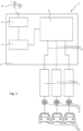
- Fig. 1 shows a schematic diagram of the device according to the invention for charging electric vehicles in a preferred embodiment.
- the device 1 comprises a housing 2 in which a central processing unit 3, which in the illustrated embodiment is designed as a microcontroller, a receiver device designed as a ripple control receiver 4, and a relay element 5 designed here as a semiconductor relay are arranged.
- the device 1 comprises a plurality of charging ports 7 (here three charging ports) arranged outside the housing 2.
- the charging ports 7 are designed as wall boxes, each of which has a Type 2 plug 9 for connecting an electric vehicle 10. It is understood that the charging ports 7 can also be arranged inside the housing 2.
- the device according to the invention is located as a stand-alone installation with a charging port for only one electric vehicle in the garage of a single-family home.
- the embodiment shown here is based on the example of a parking or underground garage which has a charging station with a large number of charging connections 7 for charging a corresponding number of electric vehicles 10.
- the ripple control receiver 4 is connected to the power supply network 6 of an energy supply company, which has a ripple control transmitter (not shown) that transmits a low-frequency ripple control signal to control the power supply network 6.
- the ripple control receiver 4 derives the control information from the ripple control transmitter by filtering the ripple control signal sent as a pulse telegram and outputs a control signal.
- the receiver device can also be a carrier frequency device that, for example, receives a PLC signal via the power grid and outputs a control signal to a potential-free contact. It is also possible for the receiver device to receive the signal externally via a radio network such as 4G, LTE, 5G, WLAN, or the like.
- the relay element 5 which in the embodiment shown here is designed as a semiconductor relay, is arranged between the receiver device 4 and the central processing unit 3.
- the relay element 5 processes the control signal output by the receiver device 4 and, in turn, signals the central processing unit 3 that the charging current for the electric vehicles 10 connected to the corresponding charging ports 7 should be reduced.
- the control signal from the receiver device 4 can different pulse sequences or codes, not only the code for immediate load shedding, i.e., shutting down or shutting down all charging processes, but also, for example, for reducing or increasing the available power to a specific value.
- the ripple control transmitter from the power supply network 6 can transmit different signals at different frequencies, which are defined in a corresponding library and which, after filtering by the ripple control receiver 4, are evaluated as pulse sequences in the relay element 5 and forwarded in a suitable manner to the central processing unit.
- the embodiment shown here describes an example application in which the ripple control transmitter sends a signal for immediate load shedding of all connected loads. This is output via the potential-free contact at the output of the ripple control receiver, meaning that either the full supply signal is present, indicating normal charging, or that no signal is present, indicating that charging is not (or no longer) permitted and that all charging connections should be reduced to zero.
- the exemplary signal for immediate load shedding is processed in such a way that the outputs or lines 8 to the charging ports 7 are now assigned corresponding signals, so that each charging current per charging port 7 is reduced to zero within a certain period of time, e.g., 10 seconds. This ensures controlled load shedding because no arcs occur at the mechanical switches or contacts in the wallboxes 7 or charging plugs, thus preventing damage to the components.
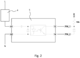
- Fig. 2 shows a section of the illustration from Fig. 1 , where the ripple control receiver 4, the relay element 5, and the connection to the central processing unit 3 are shown in more detail.
- the ripple control receiver 4 functions as a type of switch that outputs the pulse sequence of the ripple control signal to its potential-free outputs, in this case a full signal or zero.
- A1 and A2 are inputs of the semiconductor relay 5, which in the embodiment shown here is a product from Omron with the designation G3RV-SR500-D AC230.
- the identifier D AC230 in the product name indicates indicates that it is a DC output with an AC input voltage of up to 230 V.
- the full 230 V AC signal of the ripple control receiver 4 is therefore present at relay contact A1, and the neutral conductor is connected to input A2.
- This 0/1 decision for load shedding can also be implemented with different programming in the central processing unit 3, i.e., the invention is not limited to the embodiment shown here.
- more than one logic input of the microcontroller can be connected.
- other signal sequences can be transmitted as the output signal of the receiver device 4 via the relay element 5 to the central processing unit 3 and processed there, e.g., a halving of the load, a restart, a uniform ramp-up of charging currents with different durations, or the like.
- the subject matter of the invention provides a device for charging electric vehicles which enables damage-free, controlled and essentially risk-free load shedding and thus optimized load management when charging electric vehicles.
Landscapes
- Engineering & Computer Science (AREA)
- Power Engineering (AREA)
- Transportation (AREA)
- Mechanical Engineering (AREA)
- Chemical & Material Sciences (AREA)
- Manufacturing & Machinery (AREA)
- Chemical Kinetics & Catalysis (AREA)
- Electrochemistry (AREA)
- General Chemical & Material Sciences (AREA)
- Computer Networks & Wireless Communication (AREA)
- Signal Processing (AREA)
- Microelectronics & Electronic Packaging (AREA)
- Charge And Discharge Circuits For Batteries Or The Like (AREA)
- Electric Propulsion And Braking For Vehicles (AREA)
Description
- Die vorliegende Erfindung betrifft eine Vorrichtung zum Laden von Elektrofahrzeugen nach dem Oberbegriff des Anspruchs 1.
- Mit der zunehmenden Durchsetzung von Elektrofahrzeugen oder Hybridfahrzeugen im weltweiten Kraftfahrzeugmarkt steigen auch die technischen Anforderungen an die Betreiber von Stromversorgungsnetzen und insbesondere von öffentlichen oder privaten Ladestationen. Stromversorgungsnetze bzw. Elektrizitätsversorgungsnetze sind empfindliche Gebilde, die der Versorgung der Verbraucher mit elektrischer Energie dienen und dabei Kraftwerke und andere Energieumwandler miteinander verbinden. Durch exakte Überwachung von Angebot und Nachfrage wird versucht, Netzverluste zu verringern, wobei die Netzfrequenz von 50 Hz in Europa bei einer Netzspannung von 230 V eingehalten wird.
- Um bei den begrenzten Ressourcen der Energieversorgungsunternehmen ein effizientes Lastmanagement zu ermöglichen, verlangen immer mehr Energieversorgungsunternehmen die Möglichkeit, Ladestationen von Elektrofahrzeugen oder sogar einzelne für Elektrofahrzeuge dedizierte Steckdosen vom Stromversorgungsnetz abzukoppeln. Dieser Vorgang wird auch als Lastabwurf bezeichnet.
- Eine Möglichkeit des Ab- und Anschaltens von bestimmten elektrischen Verbrauchern wie z. B. elektrische Boileranlagen oder Fotovoltaikanlagen stellt die sogenannte Rundsteuertechnik dar, bei der es sich um eine Fernsteuerung über das vorhandene Stromversorgungsnetz handelt. Dabei werden Steuersignale über das Stromnetz ausschließlich von einem zentralen Rundsteuersender an dezentrale Rundsteuerempfänger übermittelt. Die Übertragung der Steuerbefehle erfolgt durch Impulsfolgen im Niederfrequenzbereich, die der normalen Netzspannung mit einer vorbestimmten Amplitude überlagert werden, wobei durch das Senden von bestimmten Codes ein Impulstelegramm entsteht.
- Ein solches abruptes Abschalten mittels der oben genannten Rundsteuertechnik von Ladestationen und oder Steckdosen unter Volllast würde bei den relativ hohen Strömen, die zum Laden von Elektrofahrzeugen erforderlich sind, zu gefährlichen Lichtbögen in den mechanischen Schaltelementen und folglich möglicherweise zu Beschädigungen der Leiterkontakte oder anderen Bauteilen in den Ladestationen oder gar in den Elektrofahrzeugen selbst führen.
-
US 2011/140659 A1 offenbart Vorrichtung zum Laden von Elektrofahrzeugen und mit einer Funktion zum Lastabwurf, die einen Anschluss an ein Stromversorgungsnetz, mindestens einen Ladeanschluss für mindestens ein Elektrofahrzeug, eine zentrale Verarbeitungseinheit aufweist, wobei die zentrale Verarbeitungseinheit dazu eingerichtet ist, ein wahlweises Reduzieren des Ladestroms eines an dem mindestens einen Ladeanschluss angeschlossenen Elektrofahrzeugs innerhalb einer vorbestimmten Zeitdauer zu bewirken, und ein Relaiselement.DE 10 2015 102449 A1 offenbart Vorrichtung zum Laden von Elektrofahrzeugen und mit einer Funktion zum kontrollierten Lastabwurf, die einen Anschluss an ein Stromversorgungsnetz, mindestens einen Ladeanschluss für mindestens ein Elektrofahrzeug, eine zentrale Verarbeitungseinheit, und eine Empfängereinrichtung aufweist.US 2014/191721 A1 Vorrichtung zum Laden von Elektrofahrzeugen und mit einer Funktion zum kontrollierten Lastabwurf die einen Anschluss an ein Stromversorgungsnetz, mindestens einen Ladeanschluss für mindestens ein Elektrofahrzeug, und eine zentrale Verarbeitungseinheit, und eine Empfängereinrichtung aufweist, wobei die zentrale Verarbeitungseinheit dazu eingerichtet ist, ein wahlweises Reduzieren des Ladestroms eines an dem mindestens einen Ladeanschluss angeschlossenen Elektrofahrzeugs innerhalb einer vorbestimmten Zeitdauer zu bewirken. - Es ist daher die Aufgabe der vorliegenden Erfindung, eine Vorrichtung zum Laden von Elektrofahrzeugen bereitzustellen, die die oben genannten Nachteile zumindest teilweise überwindet und einen möglichst beschädigungsfreien, kontrollierten und im Wesentlichen risikolosen Lastabwurf und ein optimiertes Lastmanagement beim Laden von Elektrofahrzeugen ermöglicht.
- Diese Aufgabe wird durch den Gegenstand des Anspruchs 1 gelöst. Vorteilhafte Ausführungsformen sind in den abhängigen Ansprüchen beschrieben.
- Erfindungsgemäß wird eine Vorrichtung zum Laden von Elektrofahrzeugen bereitgestellt, die einen Anschluss an ein Stromversorgungsnetz, mindestens einen Ladeanschluss für mindestens ein Elektrofahrzeug, eine zentrale Verarbeitungseinheit, eine Empfängereinrichtung, die als Rundsteuerempfänger ausgebildet und dazu eingerichtet ist, ein niederfrequentes Rundsteuersignal eines Rundsteuersenders in einem Stromversorgungsnetz (6) zu empfangen, und ein Relaiselement aufweist, das dazu eingerichtet ist, ein Steuersignal der Empfängereinrichtung zu verarbeiten und an die zentrale Verarbeitungseinheit weiterzugeben, wobei die zentrale Verarbeitungseinheit dazu eingerichtet ist, ein wahlweises Reduzieren des Ladestroms eines an dem mindestens einen Ladeanschluss angeschlossenen Elektrofahrzeugs innerhalb einer vorbestimmten Zeitdauer zu bewirken. Damit ist ein besonders schonendes, kontrolliertes, lastfreies und damit optimiertes Abschalten bzw. vom Netz Nehmen der zu ladenden Elektrofahrzeuge möglich. Durch das Verzichten auf das abrupte Abwerfen kann den Elektrofahrzeugen speziell und schonend signalisiert werden, dass sie nun interne Maßnahmen, die mit dem Reduzieren bzw. Abschalten des Ladestroms einhergehen, einleiten können. Des Weiteren können durch den Einsatz von bewährten Signalisierungstechnologien Kosten reduziert werden. Eine besondere Installation von zusätzlichen Kommunikationsgeräten ist damit nicht erforderlich.
- Vorteilhafterweise erfolgt das Reduzieren des Ladestroms für jedes an dem mindestens einen Ladeanschluss angeschlossene Elektrofahrzeug unterschiedlich. Damit wird ein kaskadenartiges Herunterfahren der Ladestationen ermöglicht, was die Gefahr von Beschädigungen weiter reduziert. Dabei kann im Rahmen eines optimierten Lastmanagements insbesondere auf die unterschiedlichen vorhandenen Ladeströme Rücksicht genommen werden.
- Mit besonderem Vorteil ist das Relaiselement ein Halbleiterrelais. Halbleiterrelais (solid-state relays; SSR) haben gegenüber elektromechanischen Relais (EMRs) den Vorteil, dass sie kleiner sind, wodurch sich eine deutliche Platzeinsparung aufgedruckten Leiterplatten ergibt, dass sie aufgrund der fehlenden beweglichen Bauteile eine bessere Systemzuverlässigkeit aufweisen, dass sie keine Anforderungen an die Ansteuerelektronik stellen und prellfrei schalten und insbesondere dass sie geringere Ausgangsspannungen aufweisen. Denn beispielsweise können mit elektromechanischen Relais zuverlässig nur Spannungen von größer als 10 V geschaltet werden.
- Mit weiterem Vorteil ist die zentrale Verarbeitungseinheit ein Mikrocontroller. Derartige Bauelemente sind flexibel programmierbar, gut verfügbar und günstig.
- Bevorzugt stellt die Empfängereinrichtung einen potentialfreien Kontakt bereit, der eindeutig eine positive oder negative Signalisierung angibt, d.h. ob ja oder nein, ob 0 oder 1. Die Empfängereinrichtung kann weiterhin ein Rundsteuerempfänger sein, der zusätzlich dazu eingerichtet ist, ein kabelgebundenes Steuersignal über ein Leitungsnetz gemäß einer Trägerfrequenztechnik wie Powerline Communication (PLC) zu empfangen, oder der zusätzlich oder alternativ dazu eingerichtet sein, ein kabelloses Steuersignal über ein Funknetz zu empfangen. Das Steuersignal kann beispielsweise ein niederfrequentes Rundsteuersignal im Frequenzbereich von 110 Hz bis etwa 2000 Hz im Stromversorgungsnetz sein. In diesem Frequenzbereich existiert eine Vielzahl von vorbestimmten Impulsfolgen, die beispielsweise in entsprechenden Bibliotheken vorhanden und bei den meisten Energieversorgungsunternehmen verfügbar sind.
- Weiterhin ist bevorzugt, dass ein Ausgangssignal des Relaiselements eine Spannung von 3,5 V nicht überschreitet. Für die Ansteuerung von Halbleiterbauelementen wie dem bevorzugten Mikrocontroller mit den üblichen Steuerspannungen von 3 V ist deshalb kein weiteres Bauelement notwendig, wodurch die Kosten für die Vorrichtung niedrig gehalten werden können.
- Mit Vorteil ist die zentrale Verarbeitungseinheit räumlich getrennt von dem mindestens einen Ladeanschluss ausgebildet und/oder ist der mindestens eine Ladeanschluss als Wallbox ausgebildet. Damit muss nicht jede einzelne Ladestation bzw. jede einzelne Aufladedose eine eigene zentrale Verarbeitungseinheit aufweisen, sondern es reicht pro Gebäude eine zentrale Verarbeitungseinheit aus, die für das Strommanagement sämtlicher angeschlossener Energieverbraucher und Energieerzeuger verantwortlich ist. Ein anschauliches Beispiel dafür ist eine Park- oder Tiefgarage mit einer Mehrzahl von Ladestationen für entsprechend viele Elektrofahrzeuge als Energieverbraucher und optional einer auf dem Dach vorhandenen Fotovoltaikanlage.
- Die Vorrichtung ist dazu eingerichtet, den Ladestrom an jedem Ladeanschluss innerhalb der vorbestimmten Zeitdauer geordnet auf Null zu reduzieren. Das vollständige Reduzieren entspricht einem kontrollierten Lastabwurf, es ist allerdings auch möglich, den Ladestrom je nach Anforderung des Lastmanagements auf einen vorbestimmten Restladestrom herunter zu regeln. Mit der vollständigen Reduktion des Ladestroms auf Null ist ein schonendes, lastfreies Abschalten der Elektrofahrzeuge vom Stromversorgungsnetz möglich. Eine Beschädigung der beteiligten Kontakt- und Schaltelemente ist damit weitgehend ausgeschlossen.
- Die Aufgabe des Lastmanagements kann von der erfindungsgemäßen Vorrichtung insbesondere dann übernommen werden, wenn die zentrale Verarbeitungseinheit dazu eingerichtet ist, weitere Energieverbraucher und/oder Energieerzeuger zu steuern. Damit ist die erfindungsgemäße Vorrichtung in der Lage, beispielsweise Boileranlagen oder Fotovoltaikanlagen kontrolliert herunter zu regeln oder auch vom Stromnetz zu nehmen.
- Weitere Eigenschaften und Vorteile der vorliegenden Erfindung ergeben sich aus den beigefügten Figuren von Ausführungsbeispielen, in denen:
- Fig. 1
- eine schematische Darstellung einer bevorzugten Ausführungsform der erfindungsgemäßen Vorrichtung und
- Fig. 2
- einen detaillierten Ausschnitt der Darstellung nach
Fig. 1 zeigt. -
Fig. 1 zeigt schematisch die erfindungsgemäße Vorrichtung zum Laden von Elektrofahrzeugen in einer bevorzugten Ausführungsform. Die Vorrichtung 1 umfasst ein Gehäuse 2, in dem eine zentrale Verarbeitungseinheit 3, die in der dargestellten Ausführungsform als Mikrocontroller ausgebildet ist, eine Empfängereinrichtung, die als Rundsteuerempfänger 4 ausgebildet ist, und ein hier als Halbleiterrelais ausgebildetes Relaiselement 5 angeordnet sind. Des Weiteren umfasst die Vorrichtung 1 eine Mehrzahl von Ladeanschlüssen 7 (hier drei Ladeanschlüsse), die außerhalb des Gehäuses 2 angeordnet sind. In der hier dargestellten Ausführungsform sind die Ladeanschlüsse 7 als Wallboxen ausgebildet, die über Typ-2-Stecker 9 jeweils zum Anschluss einen ein Elektrofahrzeug 10 verfügen. Es versteht sich, dass die Ladeanschlüsse 7 auch innerhalb des Gehäuses 2 angeordnet sein können. Dies wird insbesondere dann der Fall sein, wenn sich die erfindungsgemäße Vorrichtung als Einzelinstallation mit einem Ladeanschluss für nur ein Elektrofahrzeug in der Garage eines Einfamilienhauses befindet. Die hier dargestellte Ausführungsform orientiert sich jedoch an dem Beispiel einer Park- oder Tiefgarage, die eine Ladestation mit einer großen Mehrzahl von Ladeanschlüssen 7 zum Aufladen einer entsprechenden Anzahl von Elektrofahrzeugen 10 aufweist. - Der Rundsteuerempfänger 4 ist mit dem Stromversorgungsnetz 6 eines Energieversorgungsunternehmens verbunden, das einen (nicht dargestellten) Rundsteuersender aufweist, der zur Steuerung des Stromversorgungsnetzes 6 ein niederfrequentes Rundsteuersignal aussendet. Der Rundsteuerempfänger 4 leitet die Steuerinformationen des Rundsteuersenders durch Filterung des als Impulstelegramm geschickten Rundsteuersignals ab und gibt ein Steuersignal aus. Alternativ oder zusätzlich kann die Empfängereinrichtung auch eine Trägerfrequenzeinrichtung sein, die beispielsweise ein PLC-Signal über das Stromnetz empfängt und ein Steuersignal an einem potentialfreien Kontakt ausgibt. Es ist ebenfalls möglich, dass die Empfängereinrichtung das Signal von außen über ein Funknetz empfängt wie z.B. 4G, LTE, 5G, WLAN oder dergleichen.
- Zwischen Empfängereinrichtung 4 und zentraler Verarbeitungseinheit 3 ist das Relaiselement 5 angeordnet, das in der hier dargestellten Ausführungsform als Halbleiterrelais ausgebildet ist. Das Relaiselement 5 verarbeitet das von der Empfängereinrichtung 4 ausgegebene Steuersignal und signalisiert wiederum so der zentralen Verarbeitungseinheit 3, dass der Ladestrom für die an den entsprechenden Ladeanschlüssen 7 angeschlossenen Elektrofahrzeuge 10 zu reduzieren ist. Das Steuersignal aus der Empfängereinrichtung 4 kann unterschiedliche Impulsfolgen bzw. Codes enthalten, nicht nur den Code für den sofortigen Lastabwurf, also das Herunterfahren bzw. Abschalten aller Ladevorgänge, sondern beispielsweise für das Reduzieren oder Erhöhen der beziehbaren Leistung auf einen bestimmten Wert. Dazu kann in der hier dargestellten bevorzugten Ausführungsform der Rundsteuersender aus dem Stromversorgungsnetz 6 unterschiedliche Signale auf verschiedenen Frequenzen aussenden, die in einer entsprechenden Bibliothek definiert sind und die entsprechend nach Filterung durch den Rundsteuerempfänger 4 als Impulsfolgen in dem Relaiselement 5 ausgewertet und in geeigneter Weise an die zentrale Verarbeitungseinheit weitergeleitet werden.
- Bei der hier dargestellten Ausführungsform ist beispielhaft der Anwendungsfall beschrieben, bei dem der Rundsteuersender das Signal zum sofortigen Lastabwurf aller angeschlossenen Verbraucher aussendet. Dies wird über den potentialfreien Kontakt am Ausgang des Rundsteuerempfängers ausgegeben, d. h. dass entweder das volle Versorgungssignal anliegt und damit das normale Laden angezeigt ist, oder dass kein Signal anliegt und damit angezeigt ist, dass das Laden nicht (mehr) erlaubt ist und entsprechend alle Ladeanschlüsse auf Null reduziert werden sollen.
- In der als Mikrocontroller ausgebildeten zentralen Verarbeitungseinheit 3 erfolgt die Verarbeitung des beispielhaften Signals für den sofortigen Lastabwurf derart, dass nun die Ausgänge bzw. Leitungen 8 zu den Ladeanschlüssen 7 mit entsprechenden Signalen belegt werden, so dass jeder Ladestrom pro Ladeanschluss 7 innerhalb einer bestimmten Zeitdauer, z. B. 10 Sekunden, bis auf Null reduziert wird. Damit ist ein kontrollierter Lastabwurf gewährleistet, weil in den Wallboxen 7 bzw. Ladesteckern keine Lichtbögen an den mechanischen Schaltern oder Kontakten entstehen und somit Schäden an den Bauelementen vermieden werden.
-
Fig. 2 zeigt einen Ausschnitt der Darstellung ausFig. 1 , wobei der Rundsteuerempfänger 4, das Relaiselement 5 sowie der Anschluss an die zentrale Verarbeitungseinheit 3 ausführlicher abgebildet sind. Der Rundsteuerempfänger 4 fungiert als eine Art Schalter, der die Impulsfolge des Rundsteuersignals an seinen potentialfreien Ausgängen ausgibt, im vorliegenden Fall also volles Signal oder Null. A1 und A2 sind Eingänge des Halbleiterrelais 5, das in der hier dargestellten Ausführungsform ein Produkt der Fa. Omron mit der Bezeichnung G3RV-SR500-D AC230 ist. Die Kennung D AC230 in der Produktbezeichnung zeigt an, dass es sich um einen Gleichstromausgang (DC Output) bei einer Eingangswechselspannung von bis 230 V handelt. Am Relaiskontakt A1 liegt folglich das volle 230 V-Wechselstromsignal des Rundsteuerempfängers 4 an, auf den Eingang A2 ist der Neutralleiter geschaltet. - Innerhalb des Relaiselements 5 sind elektronische Bauelemente dargestellt, wobei die hier abgebildeten nur eine symbolische Auswahl bilden. In
Fig. 2 sind lediglich die hier wesentlichen Ausgänge 13 und 14 des Halbleiterrelais 5 gezeigt, die mit dem durch PIN_1 und PIN_2 repräsentierten Logikeingang des Mikrocontrollers bzw. der zentralen Verarbeitungseinheit verbunden sind. Damit ergibt sich folgende Schaltlogik für den beispielhaften Lastabwurf:Spannung an A1/A2: Eingang Verarbeitungseinheit: Ladestrom an Ladeanschluss: 230 VAC 0 V ja 0 VAC 3,3 V nein - Diese 0/1-Entscheidung für den Lastabwurf kann auch mit einer anderen Programmierung in der zentralen Verarbeitungseinheit 3 umgesetzt werden, d. h. die Erfindung ist nicht auf das hier dargestellte Ausführungsbeispiel beschränkt. Beispielsweise kann mehr als ein Logikeingang des Mikrocontrollers beschaltet werden. So können andere Signalfolgen als Ausgangssignal der Empfängereinrichtung 4 über das Relaiselement 5 in die zentrale Verarbeitungseinheit 3 gelangen und dort verarbeitet werden, z. B. eine Lasthalbierung, ein Neustart, ein gleichmäßiges Hochfahren von Ladeströmen mit jeweils unterschiedlichen Zeitdauern oder dergleichen mehr.
- Alternativ zu dem in der bevorzugten Ausführungsform verwendeten Halbleiterrelais 5 der Fa. Omron können auch andere gleichartige Halbleiterbauelemente verwendet werden, um die Signale der Empfängereinrichtung 4 auszuwerten und entsprechende Steuersignale an die zentrale Verarbeitungseinheit 3 weiterzuleiten.
- Die Ladeanschlüsse 7, die in der hier dargestellten Ausführungsform über die Leitungen 8 mit der zentralen Verarbeitungseinheit 3 verbunden sind, werden von dieser derart angesteuert, dass sie den Ladestrom für die angehängten Elektrofahrzeuge 10 für ca. zehn Sekunden geordnet auf Null herunter regeln und die Relaiskontakte der drei Phasen und des Nullleiters nachfolgend öffnen. Dadurch wird das Entstehen eines Lichtbogens wie beim abrupten Abschalten z. B. durch einen Schütz vermieden. Die mechanischen Kontakte der Ladeanschlüsse 7 oder der verbundenen Elektrofahrzeuge nehmen damit keinen Schaden.
- Mit dem Gegenstand der Erfindung wurde eine Vorrichtung zum Laden von Elektrofahrzeugen bereitgestellt, die einen beschädigungsfreien, kontrollierten und im Wesentlichen risikolosen Lastabwurf und damit ein optimiertes Lastmanagement beim Laden von Elektrofahrzeugen ermöglicht.
Claims (10)
- Vorrichtung (1) zum Laden von Elektrofahrzeugen (10) und mit einer Funktion zum kontrollierten Lastabwurf, die einen Anschluss an ein Stromversorgungsnetz (6), mindestens einen Ladeanschluss (7) für mindestens ein Elektrofahrzeug (10), eine zentrale Verarbeitungseinheit (3), und eine Empfängereinrichtung (4) aufweist,wobei die zentrale Verarbeitungseinheit (3) dazu eingerichtet ist, ein wahlweises Reduzieren des Ladestroms eines an dem mindestens einen Ladeanschluss (7) angeschlossenen Elektrofahrzeugs (10) innerhalb einer vorbestimmten Zeitdauer zu bewirken,dadurch gekennzeichnet, dass die Vorrichtung (1) weiterhin aufweist:ein Relaiselement (5), das dazu eingerichtet ist, ein Steuersignal der Empfängereinrichtung (4) zu verarbeiten und an die zentrale Verarbeitungseinheit (3) weiterzugeben, um der Verarbeitungseinheit (3) zu signalisieren, dass der Ladestrom für die an den entsprechenden Ladeanschlüssen (7) angeschlossenen Elektrofahrzeuge (10) zu reduzieren ist,wobei die Empfängereinrichtung (4) als Rundsteuerempfänger ausgebildet und dazu eingerichtet ist, ein niederfrequentes Rundsteuersignal eines Rundsteuersenders in einem Stromversorgungsnetz (6) zu empfangen, undwobei die Verarbeitungseinheit (3) dazu eingerichtet ist, den Ladestrom an jedem Ladeanschluss (7) innerhalb der vorbestimmten Zeitdauer geordnet auf Null zu reduzieren.
- Vorrichtung (1) nach Anspruch 1, dadurch gekennzeichnet, dass das Reduzieren des Ladestroms für jedes an dem mindestens einen Ladeanschluss (7) angeschlossene Elektrofahrzeug (10) unterschiedlich ist.
- Vorrichtung (1) nach einem der vorhergehenden Ansprüche, dadurch gekennzeichnet, dass das Relaiselement (5) ein Halbleiterrelais ist.
- Vorrichtung (1) nach einem der vorhergehenden Ansprüche, dadurch gekennzeichnet, dass die zentrale Verarbeitungseinheit (3) ein Mikrocontroller ist.
- Vorrichtung (1) nach einem der vorhergehenden Ansprüche, dadurch gekennzeichnet, dass die Empfängereinrichtung (4) dazu eingerichtet ist, ein kabelgebundenes Steuersignal über ein Leitungsnetz gemäß einer Trägerfrequenztechnik wie Powerline Communication (PLC) zu empfangen.
- Vorrichtung (1) nach einem Ansprüche 1 bis 4, dadurch gekennzeichnet, dass die Empfängereinrichtung (4) dazu eingerichtet ist ein kabelloses Steuersignal über ein Funknetz zu empfangen.
- Vorrichtung (1) nach einem der vorhergehenden Ansprüche, dadurch gekennzeichnet, dass die Empfängereinrichtung (4) ein niederfrequentes Rundsteuersignal im Frequenzbereich von 110 Hz bis etwa 2000 Hz aus dem Stromversorgungsnetz empfängt.
- Vorrichtung (1) nach einem der vorhergehenden Ansprüche, dadurch gekennzeichnet, dass ein Ausgangssignal des Relaiselements (5) eine Spannung von 3,5 V nicht überschreitet.
- Vorrichtung (1) nach einem der vorhergehenden Ansprüche, dadurch gekennzeichnet, dass die zentrale Verarbeitungseinheit (3) räumlich getrennt von dem mindestens einen Ladeanschluss (7) ausgebildet ist und/oder dass der mindestens eine Ladeanschluss (7) als Wallbox ausgebildet ist.
- Vorrichtung (1) nach einem der vorhergehenden Ansprüche, dadurch gekennzeichnet, dass die zentrale Verarbeitungseinheit (3) dazu eingerichtet ist, weitere Stromquellen und Stromverbraucher des Stromversorgungsnetzes (6) zu steuern.
Applications Claiming Priority (2)
| Application Number | Priority Date | Filing Date | Title |
|---|---|---|---|
| DE102020113235.2A DE102020113235A1 (de) | 2020-05-15 | 2020-05-15 | Ladestation für Elektrofahrzeuge |
| PCT/EP2021/061429 WO2021228587A1 (de) | 2020-05-15 | 2021-04-30 | Ladestation für elektrofahrzeuge |
Publications (3)
| Publication Number | Publication Date |
|---|---|
| EP4149790A1 EP4149790A1 (de) | 2023-03-22 |
| EP4149790B1 true EP4149790B1 (de) | 2025-06-25 |
| EP4149790C0 EP4149790C0 (de) | 2025-06-25 |
Family
ID=75769616
Family Applications (1)
| Application Number | Title | Priority Date | Filing Date |
|---|---|---|---|
| EP21722866.7A Active EP4149790B1 (de) | 2020-05-15 | 2021-04-30 | Ladestation für elektrofahrzeuge |
Country Status (9)
| Country | Link |
|---|---|
| US (1) | US20230191937A1 (de) |
| EP (1) | EP4149790B1 (de) |
| JP (1) | JP7542788B2 (de) |
| KR (1) | KR20230012002A (de) |
| CN (1) | CN115605373A (de) |
| AU (1) | AU2021269714B2 (de) |
| CA (1) | CA3177084A1 (de) |
| DE (1) | DE102020113235A1 (de) |
| WO (1) | WO2021228587A1 (de) |
Families Citing this family (4)
| Publication number | Priority date | Publication date | Assignee | Title |
|---|---|---|---|---|
| BE1028464B1 (de) * | 2020-07-09 | 2022-02-08 | Phoenix Contact Gmbh & Co | Technik zur Überwachung eines Kontakts zwischen Ladeleitern zum Laden eines Elektrofahrzeugs |
| FR3132473A1 (fr) * | 2022-02-08 | 2023-08-11 | Valeo Systemes De Controle Moteur | Borne de charge pour véhicule hybride ou électrique |
| EP4456367A1 (de) | 2023-04-28 | 2024-10-30 | Albrecht Jung GmbH & Co. KG | Elektrisches/elektronisches installationsgerät, system und verfahren zur netzstabilisierung und/oder nutzung eines niedertarifstromtarifs |
| DE102023131667A1 (de) * | 2023-11-14 | 2025-05-15 | Juice Technology AG | Verfahren zur Laststeuerung von Ladevorrichtungen |
Citations (5)
| Publication number | Priority date | Publication date | Assignee | Title |
|---|---|---|---|---|
| US20140191721A1 (en) * | 2011-08-11 | 2014-07-10 | Kabushiki Kaisha Toshiba | Electric automobile charging system and electric automobile charging device |
| US9290104B2 (en) * | 2012-08-24 | 2016-03-22 | The Regents Of The University Of California | Power control apparatus and methods for electric vehicles |
| US9762078B2 (en) * | 2012-01-25 | 2017-09-12 | Ford Global Technologies, Llc | Electric vehicle charging system adaptor |
| US9876353B2 (en) * | 2012-10-17 | 2018-01-23 | Robert Bosch Gmbh | Method and apparatus for transmitting electrical power |
| GB2576719A (en) * | 2018-08-28 | 2020-03-04 | Welsengen Ltd | Electrical vehicle charging apparatus and method |
Family Cites Families (21)
| Publication number | Priority date | Publication date | Assignee | Title |
|---|---|---|---|---|
| JPH04216297A (ja) * | 1990-12-17 | 1992-08-06 | Mitsubishi Electric Corp | 電力線通信システム |
| JP3013770B2 (ja) * | 1995-11-27 | 2000-02-28 | 株式会社戸上電機製作所 | 開閉器内におけるアーク発生部を制御する方法及び開閉器 |
| DE102009046422A1 (de) * | 2009-11-05 | 2011-05-12 | Daniel Schneider | Ladesystem für Elektrofahrzeuge |
| JP4877386B2 (ja) * | 2009-12-14 | 2012-02-15 | トヨタ自動車株式会社 | 電力管理システム |
| US9026813B2 (en) * | 2010-11-22 | 2015-05-05 | Qualcomm Incorporated | Establishing a power charging association on a powerline network |
| FR2972304A1 (fr) * | 2011-03-02 | 2012-09-07 | Commissariat Energie Atomique | Batterie avec gestion individuelle des cellules |
| JP5214764B2 (ja) * | 2011-03-25 | 2013-06-19 | 株式会社東芝 | 電気自動車充電スケジューリングシステム |
| DE102011079321A1 (de) * | 2011-07-18 | 2013-01-24 | Bayerische Motoren Werke Aktiengesellschaft | Überwachung von elektrischen Komponenten eines elektrisch betriebenen Kraftfahrzeugs auf Zerstörung |
| US8506315B2 (en) * | 2011-11-17 | 2013-08-13 | Schneider Electric USA, Inc. | Docking station for connector for electric vehicle charging station |
| JP6349384B2 (ja) * | 2013-05-15 | 2018-06-27 | ボルボトラックコーポレーション | エネルギー貯蔵システムの充電を制御する方法及び構造 |
| DE102013010774A1 (de) * | 2013-06-28 | 2014-12-31 | Rwe Ag | Verfahren zum Betreiben einer Ladestation |
| US10220719B2 (en) * | 2014-11-17 | 2019-03-05 | Siemens Industry, Inc. | EVSE-based energy automation, management, and protection systems and methods |
| DE102015102449A1 (de) * | 2015-02-20 | 2016-08-25 | Alpiq Intec Ag | Energieübertragungssteuerung zwischen Energieversorgungsnetz und Endnutzereinrichtungen basierend auf Energiefluss und Netzqualität |
| US10183586B1 (en) * | 2015-09-25 | 2019-01-22 | Evercharge, Inc. | Mixed-level electric vehicle supply equipment (EVSE) and associated charging methods for multi-type electric vehicles and non-electric vehicle devices |
| WO2018039476A1 (en) * | 2016-08-24 | 2018-03-01 | Keyssa Systems, Inc. | Charging ports with integrated contactless communication units |
| CN206834743U (zh) * | 2017-05-11 | 2018-01-02 | 中国南方电网有限责任公司调峰调频发电公司鲁布革水力发电厂 | 一种过电压限制型直流开关 |
| DE102017124469B4 (de) * | 2017-09-28 | 2021-10-14 | Engeln & Masnitza & Wagner GbR (vertretungsberechtigte Gesellschafter Michael Masnitza, 90473 Nürnberg, Tobias Wagner, 81735 München, Johannes Engeln A, 85053 Ingolstadt) | Modulare Vorrichtung zum zeitversetzten Laden von mehreren Elektrofahrzeugen an einer Ladestation |
| CN108766830B (zh) * | 2018-07-02 | 2023-09-29 | 华中科技大学 | 一种耦合式高压直流断路器 |
| CN209247994U (zh) * | 2018-09-29 | 2019-08-13 | 贵州电网有限责任公司 | 蓄电池组开路在线检测装置 |
| EP3730339B1 (de) * | 2019-04-24 | 2022-11-30 | Volvo Car Corporation | Laden eines elektrofahrzeugs |
| US11241973B2 (en) * | 2020-02-17 | 2022-02-08 | Ford Global Technologies, Llc | Pilot control circuit for charging a vehicle with a charging station |
-
2020
- 2020-05-15 DE DE102020113235.2A patent/DE102020113235A1/de not_active Withdrawn
-
2021
- 2021-04-30 US US17/923,501 patent/US20230191937A1/en not_active Abandoned
- 2021-04-30 CN CN202180035515.3A patent/CN115605373A/zh active Pending
- 2021-04-30 AU AU2021269714A patent/AU2021269714B2/en active Active
- 2021-04-30 CA CA3177084A patent/CA3177084A1/en active Pending
- 2021-04-30 EP EP21722866.7A patent/EP4149790B1/de active Active
- 2021-04-30 JP JP2022567613A patent/JP7542788B2/ja active Active
- 2021-04-30 WO PCT/EP2021/061429 patent/WO2021228587A1/de not_active Ceased
- 2021-04-30 KR KR1020227043749A patent/KR20230012002A/ko active Pending
Patent Citations (5)
| Publication number | Priority date | Publication date | Assignee | Title |
|---|---|---|---|---|
| US20140191721A1 (en) * | 2011-08-11 | 2014-07-10 | Kabushiki Kaisha Toshiba | Electric automobile charging system and electric automobile charging device |
| US9762078B2 (en) * | 2012-01-25 | 2017-09-12 | Ford Global Technologies, Llc | Electric vehicle charging system adaptor |
| US9290104B2 (en) * | 2012-08-24 | 2016-03-22 | The Regents Of The University Of California | Power control apparatus and methods for electric vehicles |
| US9876353B2 (en) * | 2012-10-17 | 2018-01-23 | Robert Bosch Gmbh | Method and apparatus for transmitting electrical power |
| GB2576719A (en) * | 2018-08-28 | 2020-03-04 | Welsengen Ltd | Electrical vehicle charging apparatus and method |
Also Published As
| Publication number | Publication date |
|---|---|
| US20230191937A1 (en) | 2023-06-22 |
| AU2021269714A1 (en) | 2022-12-08 |
| DE102020113235A1 (de) | 2021-11-18 |
| JP7542788B2 (ja) | 2024-09-02 |
| AU2021269714B2 (en) | 2024-03-14 |
| EP4149790A1 (de) | 2023-03-22 |
| EP4149790C0 (de) | 2025-06-25 |
| KR20230012002A (ko) | 2023-01-25 |
| CA3177084A1 (en) | 2021-11-18 |
| CN115605373A (zh) | 2023-01-13 |
| WO2021228587A1 (de) | 2021-11-18 |
| JP2023525071A (ja) | 2023-06-14 |
Similar Documents
| Publication | Publication Date | Title |
|---|---|---|
| EP4149790B1 (de) | Ladestation für elektrofahrzeuge | |
| EP3688858B1 (de) | Modulare vorrichtung zum zeitversetzten laden von mehreren elektrofahrzeugen einer ladestation | |
| EP3406029B1 (de) | Trennvorrichtung für einen photovoltaischen string, solaranlage und betriebsverfahren für eine solaranlage mit photovoltaischem string | |
| DE102014108657A1 (de) | Schutzschaltgerät | |
| WO2018219544A1 (de) | Verfahren zum betreiben einer fahrzeugladevorrichtung, fahrzeugladevorrichtung sowie system aus einer sensorvorrichtung und einer fahrzeugladevorrichtung | |
| DE102012208297A1 (de) | Stromversorgungsanordnung mit Phasenwahl für eine Leuchte | |
| DE102014019725B3 (de) | Elektronische Schaltvorrichtung und elektronisches Schaltverfahren | |
| DE102021104573A1 (de) | Vorrichtung, Ladestation, System und Verfahren | |
| EP0402654B1 (de) | Anschlussvorrichtung für den Anschluss elektrischer Verbraucher | |
| EP2732526B1 (de) | Netzüberwachungsvorrichtung | |
| EP0437696B1 (de) | Fernschalt- oder fernsteuerbare Anschlussvorrichtung | |
| WO2021023604A1 (de) | Energieversorgungsanlage mit einer koppeleinrichtung | |
| DE202006020319U1 (de) | Fahrzeug mit einem Wohnaufbau | |
| DE102014104837B3 (de) | Elektronische Schaltvorrichtung und elektronisches Schaltverfahren | |
| DE102021121127A1 (de) | Verfahren zum Betreiben eines Netzmanagementsystems für ein lokales Energienetz, Computerprogrammprodukt sowie Netzmanagementsystem | |
| EP4015285A1 (de) | Anordnung zur integration in eine ladevorrichtung für wenigstens ein elektrofahrzeug | |
| DE102017011373A1 (de) | Mess- und Steuerelektronik für Niederspannungsschaltanlagen | |
| EP4515658A2 (de) | Energieversorgungssystem und verfahren zum betrieb eines energieversorgungssystems | |
| EP2594858A1 (de) | Verfahren und System zum ferngesteuerten Ansteuern von dezentralen Einzelklimageräten ohne Vernetzungsschnittstelle | |
| EP3596792B1 (de) | Elektrisches energieversorgungsnetz und verfahren zu dessen betrieb | |
| DE19927869C1 (de) | Elektroinstallationseinrichtung für Gebäude | |
| DE102015008698A1 (de) | Fehlerstrom-Schutzeinrichtung für einen elektrischen Verbraucher | |
| EP3024106B1 (de) | Zuschaltvorrichtung für eine elektrische anlage zum zeitverzögerten anfahren nach empfang eines steuersignals | |
| EP1859989A1 (de) | Elektrische Anlage für einen Wohnaufbau | |
| WO2024028442A1 (de) | Photovoltaikanlage mit sicherheitsabschaltung |
Legal Events
| Date | Code | Title | Description |
|---|---|---|---|
| STAA | Information on the status of an ep patent application or granted ep patent |
Free format text: STATUS: UNKNOWN |
|
| STAA | Information on the status of an ep patent application or granted ep patent |
Free format text: STATUS: THE INTERNATIONAL PUBLICATION HAS BEEN MADE |
|
| PUAI | Public reference made under article 153(3) epc to a published international application that has entered the european phase |
Free format text: ORIGINAL CODE: 0009012 |
|
| STAA | Information on the status of an ep patent application or granted ep patent |
Free format text: STATUS: REQUEST FOR EXAMINATION WAS MADE |
|
| 17P | Request for examination filed |
Effective date: 20221028 |
|
| AK | Designated contracting states |
Kind code of ref document: A1 Designated state(s): AL AT BE BG CH CY CZ DE DK EE ES FI FR GB GR HR HU IE IS IT LI LT LU LV MC MK MT NL NO PL PT RO RS SE SI SK SM TR |
|
| DAV | Request for validation of the european patent (deleted) | ||
| DAX | Request for extension of the european patent (deleted) | ||
| RAP3 | Party data changed (applicant data changed or rights of an application transferred) |
Owner name: JUICE TECHNOLOGY AG |
|
| STAA | Information on the status of an ep patent application or granted ep patent |
Free format text: STATUS: EXAMINATION IS IN PROGRESS |
|
| 17Q | First examination report despatched |
Effective date: 20240409 |
|
| GRAP | Despatch of communication of intention to grant a patent |
Free format text: ORIGINAL CODE: EPIDOSNIGR1 |
|
| STAA | Information on the status of an ep patent application or granted ep patent |
Free format text: STATUS: GRANT OF PATENT IS INTENDED |
|
| RIC1 | Information provided on ipc code assigned before grant |
Ipc: H04B 3/54 20060101ALI20241014BHEP Ipc: H04L 12/10 20060101ALI20241014BHEP Ipc: H02J 1/14 20060101ALI20241014BHEP Ipc: H01M 10/42 20060101ALI20241014BHEP Ipc: H01M 10/44 20060101ALI20241014BHEP Ipc: B60L 53/63 20190101ALI20241014BHEP Ipc: H02J 7/00 20060101ALI20241014BHEP Ipc: B60L 53/66 20190101ALI20241014BHEP Ipc: B60L 53/14 20190101AFI20241014BHEP |
|
| INTG | Intention to grant announced |
Effective date: 20241030 |
|
| GRAS | Grant fee paid |
Free format text: ORIGINAL CODE: EPIDOSNIGR3 |
|
| GRAA | (expected) grant |
Free format text: ORIGINAL CODE: 0009210 |
|
| STAA | Information on the status of an ep patent application or granted ep patent |
Free format text: STATUS: THE PATENT HAS BEEN GRANTED |
|
| AK | Designated contracting states |
Kind code of ref document: B1 Designated state(s): AL AT BE BG CH CY CZ DE DK EE ES FI FR GB GR HR HU IE IS IT LI LT LU LV MC MK MT NL NO PL PT RO RS SE SI SK SM TR |
|
| REG | Reference to a national code |
Ref country code: GB Ref legal event code: FG4D Free format text: NOT ENGLISH |
|
| REG | Reference to a national code |
Ref country code: CH Ref legal event code: EP |
|
| REG | Reference to a national code |
Ref country code: CH Ref legal event code: EP |
|
| REG | Reference to a national code |
Ref country code: IE Ref legal event code: FG4D Free format text: LANGUAGE OF EP DOCUMENT: GERMAN |
|
| REG | Reference to a national code |
Ref country code: DE Ref legal event code: R096 Ref document number: 502021007851 Country of ref document: DE |
|
| U01 | Request for unitary effect filed |
Effective date: 20250724 |
|
| U07 | Unitary effect registered |
Designated state(s): AT BE BG DE DK EE FI FR IT LT LU LV MT NL PT RO SE SI Effective date: 20250730 |
|
| PG25 | Lapsed in a contracting state [announced via postgrant information from national office to epo] |
Ref country code: NO Free format text: LAPSE BECAUSE OF FAILURE TO SUBMIT A TRANSLATION OF THE DESCRIPTION OR TO PAY THE FEE WITHIN THE PRESCRIBED TIME-LIMIT Effective date: 20250925 Ref country code: GR Free format text: LAPSE BECAUSE OF FAILURE TO SUBMIT A TRANSLATION OF THE DESCRIPTION OR TO PAY THE FEE WITHIN THE PRESCRIBED TIME-LIMIT Effective date: 20250926 |
|
| PG25 | Lapsed in a contracting state [announced via postgrant information from national office to epo] |
Ref country code: HR Free format text: LAPSE BECAUSE OF FAILURE TO SUBMIT A TRANSLATION OF THE DESCRIPTION OR TO PAY THE FEE WITHIN THE PRESCRIBED TIME-LIMIT Effective date: 20250625 |
|
| PG25 | Lapsed in a contracting state [announced via postgrant information from national office to epo] |
Ref country code: RS Free format text: LAPSE BECAUSE OF FAILURE TO SUBMIT A TRANSLATION OF THE DESCRIPTION OR TO PAY THE FEE WITHIN THE PRESCRIBED TIME-LIMIT Effective date: 20250925 |
|
| PG25 | Lapsed in a contracting state [announced via postgrant information from national office to epo] |
Ref country code: IS Free format text: LAPSE BECAUSE OF FAILURE TO SUBMIT A TRANSLATION OF THE DESCRIPTION OR TO PAY THE FEE WITHIN THE PRESCRIBED TIME-LIMIT Effective date: 20251025 |
|
| PG25 | Lapsed in a contracting state [announced via postgrant information from national office to epo] |
Ref country code: SM Free format text: LAPSE BECAUSE OF FAILURE TO SUBMIT A TRANSLATION OF THE DESCRIPTION OR TO PAY THE FEE WITHIN THE PRESCRIBED TIME-LIMIT Effective date: 20250625 |
|
| PG25 | Lapsed in a contracting state [announced via postgrant information from national office to epo] |
Ref country code: CZ Free format text: LAPSE BECAUSE OF FAILURE TO SUBMIT A TRANSLATION OF THE DESCRIPTION OR TO PAY THE FEE WITHIN THE PRESCRIBED TIME-LIMIT Effective date: 20250625 |
|
| PG25 | Lapsed in a contracting state [announced via postgrant information from national office to epo] |
Ref country code: PL Free format text: LAPSE BECAUSE OF FAILURE TO SUBMIT A TRANSLATION OF THE DESCRIPTION OR TO PAY THE FEE WITHIN THE PRESCRIBED TIME-LIMIT Effective date: 20250625 |
|
| PG25 | Lapsed in a contracting state [announced via postgrant information from national office to epo] |
Ref country code: SK Free format text: LAPSE BECAUSE OF FAILURE TO SUBMIT A TRANSLATION OF THE DESCRIPTION OR TO PAY THE FEE WITHIN THE PRESCRIBED TIME-LIMIT Effective date: 20250625 |
|
| PG25 | Lapsed in a contracting state [announced via postgrant information from national office to epo] |
Ref country code: ES Free format text: LAPSE BECAUSE OF FAILURE TO SUBMIT A TRANSLATION OF THE DESCRIPTION OR TO PAY THE FEE WITHIN THE PRESCRIBED TIME-LIMIT Effective date: 20250625 |
|
| PGFP | Annual fee paid to national office [announced via postgrant information from national office to epo] |
Ref country code: GB Payment date: 20260317 Year of fee payment: 6 |
|
| PLBE | No opposition filed within time limit |
Free format text: ORIGINAL CODE: 0009261 |
|
| STAA | Information on the status of an ep patent application or granted ep patent |
Free format text: STATUS: NO OPPOSITION FILED WITHIN TIME LIMIT |