EP4150159B1 - Sperrmechanismus - Google Patents
Sperrmechanismus Download PDFInfo
- Publication number
- EP4150159B1 EP4150159B1 EP21728297.9A EP21728297A EP4150159B1 EP 4150159 B1 EP4150159 B1 EP 4150159B1 EP 21728297 A EP21728297 A EP 21728297A EP 4150159 B1 EP4150159 B1 EP 4150159B1
- Authority
- EP
- European Patent Office
- Prior art keywords
- wheel
- shaft
- boom
- main shaft
- movement
- Prior art date
- Legal status (The legal status is an assumption and is not a legal conclusion. Google has not performed a legal analysis and makes no representation as to the accuracy of the status listed.)
- Active
Links
Images





Classifications
-
- E—FIXED CONSTRUCTIONS
- E01—CONSTRUCTION OF ROADS, RAILWAYS, OR BRIDGES
- E01F—ADDITIONAL WORK, SUCH AS EQUIPPING ROADS OR THE CONSTRUCTION OF PLATFORMS, HELICOPTER LANDING STAGES, SIGNS, SNOW FENCES, OR THE LIKE
- E01F13/00—Arrangements for obstructing or restricting traffic, e.g. gates, barricades ; Preventing passage of vehicles of selected category or dimensions
- E01F13/04—Arrangements for obstructing or restricting traffic, e.g. gates, barricades ; Preventing passage of vehicles of selected category or dimensions movable to allow or prevent passage
- E01F13/06—Arrangements for obstructing or restricting traffic, e.g. gates, barricades ; Preventing passage of vehicles of selected category or dimensions movable to allow or prevent passage by swinging into open position about a vertical or horizontal axis parallel to the road direction, i.e. swinging gates
-
- B—PERFORMING OPERATIONS; TRANSPORTING
- B61—RAILWAYS
- B61L—GUIDING RAILWAY TRAFFIC; ENSURING THE SAFETY OF RAILWAY TRAFFIC
- B61L29/00—Safety means for rail/road crossing traffic
- B61L29/04—Gates for level crossings
Definitions
- the present application describes a barrier mechanism for level crossing control systems.
- the increase in the size of the counterweights also leads to an increase in setbacks when the meteorological conditions are not favourable, particularly when there is precipitation of ice flakes and crystals, which leads to the formation of solid crystalline layers that block the regular movement of the boom.
- CN 204 059 230 U discloses a prior art barrier mechanism comprising a compression spring set replacing the counterweight.
- the present application describes a barrier mechanism comprising a mechanism; and a boom, which is fixed at one of the extremities to the mechanism by means of a fixation system; wherein the mechanism comprises an equalizer system, comprising a main shaft comprising a wheel and a connecting cam, a set of compression springs, a set of transmission chains, mechanically interconnecting the set of compression springs to the main shaft by means of the connecting cam; and a reduction set, comprising a DC motor comprising a reel, a shaft comprising a crown wheel and a wheel, and a shaft comprising a wheel and a wheel, wherein the motor provides connection to the shaft by means of the mechanic connection between the reel and the crown wheel, wherein the shaft provides rotation to the shaft by means of the mechanic connection between the wheel and the wheel, and wherein the shaft provides rotation to the main shaft by means of the mechanical connection between the wheel and the wheel of the equalizer system.
- an equalizer system comprising a main shaft comprising a wheel and a connecting cam, a set of compression springs
- the mechanism comprises an automaton that commands the rising and lowering of the boom by means of the action of the DC motor which transmits rotation to the main shaft.
- the barrier mechanism comprises additionally a metallic skirt.
- the boom comprises the use of two or more profiles that are compatible with each other, being an inner profile and an outer profile.
- the outer profile of the boom allows the installation of light signals and/or a metallic skirt.
- the inner profile of the boom allows the junction of two outer profiles of the boom and the adjustment of the length of the boom at the place of installation.
- the set of transmission chains comprises a set of four chains bolted to the connection brace which is still welded to the main shaft.
- connection brace transmits the swaying movement of the main shaft to the chains by means of a dowel which operates as a mechanical joint pin.
- the main shaft comprises additionally a manual drive system comprised of a conical set with a 2:1 transmission ratio to the respective main shaft, wherein the referred system is activated by a handle.
- the main shaft comprises additionally a position detection system of the boom comprising eccentric components and microswitches, wherein the eccentric components activate the referred microswitches throughout the rotation movement of the main shaft.
- the present application further describes the automatic operating method for the barrier mechanism, wherein the mechanism, after receiving an electric command from the control system, comprises the steps of: the DC motor transmits the rotation movement to the auxiliary shaft of the motor, by means of a flexible coupling, which, by means of the worm screw transmits rotation to the reel which in turn will activate the main transmission system; - the transference of the rotation movement is made by means of a reduction with a 40:1 rotation to the crown wheel installed in the shaft 1, wherein the maximum binary of the system is controlled by means of the binary limiter and the reduction in speed and the progressive increase in torque are provided by the wheel 2; the rotation movement provided on shaft 2, transmitted by the wheel 3 by means of the existing connection with the wheel 2, will in turn move the shaft 2, transmitting the rotation movement to the wheel 4;
- the manual operating method of the barrier mechanism is further described, wherein the mechanism comprises the steps of: - Electrically turning off the mechanism; - Unblocking the passage of the handle for manual drive; - Engaging the manual drive system to the main transmission system, so that the engagement point is made by means of a direct transmission using cylindrical gearings with straight teeth; - The rotation movement is transmitted from the reel to the auxiliary shaft of the motor from the worm screw, whereby the sequence of movements henceforth is equal to that of the automatic drive.
- the present application further describes a boom comprising at least one outer profile comprising a lower support rail, and at least one socket cavity, and at least one inner profile comprising a lower projection socket, and at least one socket rectangle, wherein the at least one outer profile and the at least one inner profile are coupled by means of the mechanical union between the at least one socket cavity and the at least one socket rectangle, and between the lower support rail and the lower projection socket.
- the present application describes a barrier mechanism for level crossing control systems. It is an equipment that is designed to maximize the protection in level crossings, mitigating risk behaviour and situations.
- the static and dynamic balance of the main shaft is obtained by means of a set of mechanical elements comprised of steel cams, chains, forks, and a set of compression springs which, when compressed have the function of compensating the moment of force caused by the boom on the main shaft.
- the mechanism is controlled by an automaton which, when it receives the information that the train is approaching, it commands the barrier to lower (obstructing the passage of road vehicles or pedestrians to the railway line), and when it receives the indication of the effective passing of the train, again commands the barrier, this time to rise, enabling once more the road and pedestrian circulation.
- the equalizer system of the main shaft was the solution developed with the purpose of complying with the requirement of absence of conventional counterweights, which are usually used in this type of application.
- the fact that the counterweights are not used results in a reduction of the working space of the arm of the mechanism, and this reduction mitigates the risk of material damage and harm to physical integrity, thus resulting in a system that is conducive to the well-being of all the passers-by on the road and the professionals in the area of railway signalization.
- the function of the equalizer system of the main shaft is to balance the moment of force on the main shaft. This mechanical system compensates the torque generated by the weight of the boom when it is in the horizontal position and balances the forces that are applied to the main shaft when the boom is moving. This compensation of the force applied results in a considerably stable movement of the boom.
- the distinctive factor of the mechanism developed resides in applying a set of compression springs, to guarantee the static balance and the dynamic stability of the boom of the barrier mechanism of a level crossing.
- the solution developed is designed as an integral part of the level crossing system, whereby it is possible to configure lengths, types of signalling and other secondary accessories to better adapt to each scenario and type of installation.
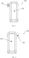
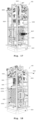
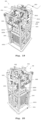
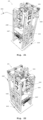
- the present application describes a barrier mechanism (100) for level crossing control systems.
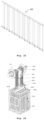
- the barrier mechanism (100) in one of the proposed embodiments, comprises the use of three components, the mechanism (102) itself, the boom (101) and the metallic skirt (103).
- the main function of the barrier mechanism (100) is to protect users in circulation on the road from a situation of imminent danger whenever it is necessary to cross the railway lines.
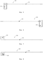
- the mechanism (100) is characterized by the conventional movement, wherein a boom (101) describes a circular movement of 0° (barrier in closed position - horizontal position) to 90° (barrier in open position - vertical position), there existing a boom fixation point (101) to the main shaft (1020) of the mechanism.
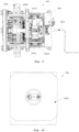
- the torque and the speed provided on the main shaft (1020) of the mechanism are resulting from the transmission of the mechanical power of a DC motor (1028), and of a reduction set, comprised by a three-floor reduction, resulting in the mechanical efforts necessary to generate the boom movement.
- this mechanism differs from the overwhelming majority of the equipment in this field of application since the balance system of the main shaft is not made in the conventional manner, resorting to the use of bulky and heavy solid counterweights on the opposite side of the road, which is a solution that is used worldwide.
- This traditional solution due to its robustness and the volume of working space of the counterweights, can cause certain inconveniences to the passers-by and workers that are skilled in the mechanism. These constraints can result in harm to the physical integrity of a passer-by/maintenance technician and in material damages.
- the stability of the movement is internally guaranteed, resulting in the elimination of the volume of working space of the counterweights and in the elimination of the risk deriving from the conventional solution.
- the static and dynamic balance of the main shaft is obtained by means of a set of mechanical elements (steel cam, chains, forks, and spring pack) which have the function of compensating the moment of force caused by the boom on the main shaft.
- the boom (101), used together with the mechanism (102), consists in two profiles that are compatible with each other: the outer profile (1011) and the inner profile (1012).
- the outer profile (1011) is constructively designed to resist the adverse meteorological conditions and has the function of being sufficiently visible to the road users to indicate the presence of a level crossing barrier, allow the installation of light signals as well as the installation of a metallic skirt to obstruct the passage of passers-by through the lower part of the boom.
- the outer profile (1011) of the boom (101) presents, in the lower area, a lower support rail (10111) which is destined to the fixation of accessories, namely, the metallic skirt (103) .
- the inner profile (1012) of the boom (101) has two functions: the first one is to unite two modules of the outer boom profile (1011), so that it is possible to configure the boom (101) in several lengths, and the second function is to guarantee that, apart from the fixed length originating from each boom configuration (101), there exists the possibility of customizing and adjusting the final length of the boom (101) at the location of the installation.
- the metallic skirt (103) acts as an accessory and it is conceived to supplement the obstruction of passage exerted by the boom preventing the road users from passing through the lower part of the boom.
- This component is optional and the fixation thereof to the boom can be made by means of screws.
- Main transmission system is the designation given to the set of mechanical elements of the mechanism which has the primary function in the movement of the level crossing barrier. This set is permanently demanded, whether during automatic drive, whether during the manual drive of the mechanism.
- the movement of the mechanism is generated from the electric drive of a motor organ (1028) (CC Motor, 24V, 1500rpm, >1.2 N.m), which has the flange vertically fixed to the metallic structure that gives body to the mechanism.
- This motor organ is responsible for creating the rotation movement (the translation movement is restricted to the three shafts and the rotation axis is perpendicular to the XZ plan) necessary for the automatic operation of the barrier mechanism (101).
- the auxiliary motor shaft is a propelled element which has a rotation speed and rotation direction that is equal to that debited by the motor.
- the worm screw is fixed to the auxiliary shaft of the motor, since it is necessary to transmit the movement to the shaft (10214), by means of the semi-globoid crown wheel, wheel, which is fixed to the binary limiter that is found keyed to the shaft (10214).
- the movement transmission is transversal, irreversible, and has a 40:1 transmission relation. This transmission corresponds to a movement by direct contact by means of a gear joint.
- the third transmission floor is the last step in the main transmission, and it guarantees that the upwards movement and the declining movement of the boom are executed, according to the swaying movement of the main shaft.
- the equalizer system of the main shaft is the solution developed with the purpose of meeting the requirement of absence of conventional counterweights, which are commonly used in this type of application.
- the fact that the counterweights are not used results in a reduction in the working space of the mechanism. This reduction has the main effect of mitigating the risk of material damage and damage to the physical integrity, thus resulting in a system that is conducive to the well-being of all the road passers-by and the workers in the area of railway signalling.
- the function of the main shaft equalizer system is to balance the moment of force in the main shaft. This mechanical system compensates the torque generated by the weight of the boom when it is in the horizontal position and balances the forces applied to the main shaft when the boom is moving. This instantaneous compensation of the moment of force in the main shaft results in a considerably stable movement of the boom.
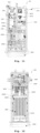
- This equalizer system consists in a set of cylindrical compression springs with a configurable distribution, whereby the number thereof can vary between the use of 0 and 14 springs, always in even numbers and distributed in a specific manner, so that the exertion of the springs is always distributed symmetrically and uniformly in the structure that surrounds them.
- the movement responsible for the compression of the set of springs is initiated by the DC motor and is transmitted by the main shaft to the spring pack by means of a flexible intermediary connection, using a set of four transmission chains, which are bolted to the connecting braces, which are components that are directly welded to the main shaft.
- the connecting brace transmits the swaying movement of the main shaft to the chains by means of a dowel which operates as a mechanical joint pin.
- This swaying movement of the connecting brace cam is converted in the translation movement in height of the sliding plate, which is the component that compresses the springs when it is subjected to the exertion of the chains in the upwards direction.
- the movement of the sliding plate is made possible and conducted by two M20 rods, which operate with a translation joint and guarantee the lightness and uniformity of the movement.
- the compression springs in one of the proposed embodiments, present 410mm length, 73mm outer diameter and one compresses 1mm when 18,915 N are applied in the direction of the spring shaft.
- the movement that originates the compression of the spring set is generated in the main shaft and transmitted to the spring set by means of a semi-flexible chain of mechanical elements (connecting brace welded to the shaft, chains, forks, connecting profile and M20 rods), particularly dimensioned and designed for this application.
- the resulting force of this compression maintains the flexible part in constant traction and allows balancing the moment of force in the main shaft.
- the connecting braces are eccentric fixed components having a thickness that is capable of mechanically driving the microswitches.
- the movement that is made by these eccentric components is an alternating curvilinear shuttle movement. It is an upper contact, since the contact is made by means of a line that corresponds to the intersection of the microswitch rolling head and the outer perimeter of the connecting brace.
- the handle is installed in the horizontal shaft of the manual drive, and by means of the application of a rotation in the horizontal shaft it is possible to operate the mechanism.
- the movement is originated by the user (maintenance technician of the railway network).
- the engagement point is made by means of a direct transmission using cylindrical gears with straight teeth.
- the rotation movement is transmitted from the reel (10285) to the auxiliary shaft of the motor (10284).
- the components (10282, 10283, 10284 and 10285) have a rotation speed and torque commanded by the user. From the worm screw (10283), the sequence of movements remains the same as that of the automatic drive.
Landscapes
- Engineering & Computer Science (AREA)
- Mechanical Engineering (AREA)
- Architecture (AREA)
- Civil Engineering (AREA)
- Structural Engineering (AREA)
- Forklifts And Lifting Vehicles (AREA)
- Jib Cranes (AREA)
Claims (12)
- Schrankenantrieb (100), bestehend auseiner Antriebseinheit (102) undeinem Schrankenbaum (101), der an einem Ende an der Antriebseinheit (102) mittels eines Befestigungssystems befestigt ist;worin die Antriebseinheit (102) Folgendes umfasst ein Ausgleichssystem (104), bestehend auseiner Hauptwelle (1020) mit einem Verbindungsnocken (10201), einem Satz von Druckfedern (1025),einem Satz Getriebeketten (1024), der den Satz von Druckfedern (1025) über den Verbindungsnocken (10201) mechanisch mit der Hauptwelle (1020) verbindet; undeinem Reduziergetriebe, bestehend auseinem Gleichstrommotor (1028) mit einem Rad (10285),einer ersten Welle (10214), bestehend aus einem Schneckenrad (10216) und einem zweiten Zahnrad (10215), undeiner zweiten Welle (10212), bestehend aus einem dritten Zahnrad (10211) und einem vierten Zahnrad (10213),worin der Motor (1028) eine Verbindung mit der ersten Welle (10214) mittels der mechanischenVerbindung zwischen der Rolle (10285) und dem Schneckenrad (10216) bereitstellt,worin die erste Welle (10214) die Drehung der zweiten Welle (10212) mittels der mechanischen Verbindung zwischen dem zweiten Zahnad (10215) und dem dritten Zahnrad (10211) bewirkt, undworin die zweite Welle (10212) die Drehung der Hauptwelle (1020) mittels der mechanischen Verbindung zwischen dem vierten Zahnrad (10213) und dem fünften Zahnrad (1021) des Ausgleichsystems bewirkt.
- Schrankenantrieb (100) gemäß Anspruch 1, worin die Antriebseinheit (102) einen Automaten beinhaltet, der das Anheben oder Absenken des Schrankenbaums (101) mittels der Betätigung des Gleichstrommotors (1028) steuert, der die Drehung auf die Hauptwelle (1020) überträgt.
- Schrankenantrieb (100) gemäß Anspruch 1, der zusätzlich eine metallische Schürze (103) umfasst.
- Schrankenantrieb (100) gemäß Anspruch 1, worin der Schrankenbaum (101) die Verwendung von zwei oder mehr miteinander kompatiblen Profilen umfasst, die aus einem Innenprofil (1012) und einem Außenprofil (1011) bestehen.
- Schrankenantrieb (100) gemäß Anspruch 1 und Anspruch 4, worin das äußere Profil (1011) des Schrankenbaums die Installation von Lichtsignalen und/oder einer metallischen Schürze (103) ermöglicht.
- Schrankenantrieb (100) gemäß den Ansprüchen 1, 4 und 5, worin das Innenprofil (1012) des Schrankenbaums die Verbindung von zwei Modulen des Außenprofils (1011) des Schrankenbaums und die Einstellung der Länge des Schrankenbaums (101) am Einbauort ermöglicht.
- Schrankenantrieb (100) gemäß Anspruch 1, worin der Satz von Getriebeketten (1024) einen Satz von vier Ketten umfasst, die an einer Verbindungslasche (10201) angeschraubt sind, die mit der Hauptwelle (1020) verschweißt ist.
- Schrankenantrieb (100) gemäß Anspruch 1 und 7, worin die Verbindungslasche (10201) die Pendelbewegung der Hauptwelle (1020) auf den Satz von Getriebeketten (1024) über einen Dübel überträgt, der als mechanischer Gelenkbolzen funktioniert.
- Schrankenantrieb (100) gemäß Anspruch 1, worin die Hauptwelle (1020) zusätzlich ein manuelles Antriebssystem umfasst, das aus einem Kegelradsatz mit einem 2:1 Übersetzungsverhältnis zur entsprechenden vertikalen Welle besteht, worin das genannte System durch eine Kurbel (1022) angetrieben wird.
- Schrankenantrieb (100) gemäß Anspruch 1, worin die Hauptwelle (1020) zusätzlich ein Positionserfassungssystem (1026) des Schrankenbaums (101) umfasst, das exzentrische Komponenten und Mikroschalter enthält, worin die exzentrischen Komponenten die genannten Mikroschalter während der Drehbewegung der Hauptwelle (1020) betätigen.
- Verfahren zum automatischen Betrieb des Schrankenantriebs (100) gemäß einem der vorhergehenden Ansprüche, worin die Antriebseinheit (102) nach Empfang eines elektrischen Befehls von einem Steuersystem die folgenden Schritte ausführt:- Der Gleichstrommotor (1028) überträgt die Drehbewegung über eine flexible Kupplung (10282) auf eine Hilfswelle des Motors (10284), wobei mittels einer Schnecke (10283) die Drehung auf das Rad (10285) übertragen wird, das wiederum das Hauptübertragungssystem aktiviert;- die Übertragung der Drehbewegung erfolgt durch eine Untersetzung mit einem Verhältnis von 40:1 auf das Schneckenrad (10216), das auf der ersten Welle (10214) montiert ist, wobei ein maximales Drehmoment des Systems mittels eines Drehmomentbegrenzers (10217) gesteuert und eine Verringerung der Drehzahl sowie eine progressive Erhöhung des Drehmoments durch das zweite Zahnrad (10215) vorgenommen wird.- die auf der zweiten Welle (10212) vorgesehene Drehbewegung, die vom dritten Zahnrad (10211) mittels der bestehenden Verbindung mit dem zweiten Zahnrad (10215) übertragen wird, bewegt wiederum die zweite Welle (10212), welche die Drehbewegung auf das vierte Zahnrad (10213) überträgt;- das vierte Zahnrad (10213) überträgt die Drehung der zweiten Welle (10212) auf die Hauptwelle (1020) durch die bestehende Verbindung mit dem fünften Zahnrad (1021), die wiederum mittels der vorhandenen Verbindung mit den Verbindungsnocken (10201) die Bewegung des Ausgleichssystems (104), bestehend aus dem Satz Druckfedern (1025), ermöglicht, das durch die flexible Zwischenverbindung zwischen dem genannten Satz Druckfedern (1025) und den Verbindungsnocken angetrieben wird (10201);- die Aufwärts- oder Abwärtsbewegung des Getriebekettensatzes (1024) bewirkt die Aufwärts- oder Abwärtsbewegung einer beweglichen Platten-Druckstange (10252) mittels einer vorhandenen Verbindung mit einem gabelförmigen Verbindungsprofil (10253), wodurch das Heben oder Senken einer Gleitplatte (10251)verursacht wird, die den Satz von Druckfedern (1025) komprimiert oder dekomprimiert.
- Verfahren zur manuellen Betätigung des Schrankenantriebs (100) gemäß Anspruch 9, worin das Verfahren die folgenden Schritte umfasst:- Elektrische Abschaltung der Antriebseinheit (102);- Freigabe der Passage der Kurbel (1022) für den manuellen Antrieb;- Eingreifen des manuellen Antriebssystems in das Hauptgetriebssystem, so dass der Eingriffspunkt mittels der Direktübertragung unter Verwendung einer Stirnradverzahnung mit geraden Zähnen erfolgt;- Eine Drehbewegung wird vom Rad (10285) auf die Hilfswelle des Motors (10284) von einer Schnecke (10283) übertragen, wobei der Bewegungsablauf fortan derselbe wie der des automatischen Antriebs ist.
Priority Applications (1)
| Application Number | Priority Date | Filing Date | Title |
|---|---|---|---|
| EP23182136.4A EP4253191B1 (de) | 2020-05-14 | 2021-05-12 | Sperrmechanismus |
Applications Claiming Priority (2)
| Application Number | Priority Date | Filing Date | Title |
|---|---|---|---|
| PT11638020 | 2020-05-14 | ||
| PCT/IB2021/054043 WO2021229459A1 (en) | 2020-05-14 | 2021-05-12 | Barrier mechanism |
Related Child Applications (2)
| Application Number | Title | Priority Date | Filing Date |
|---|---|---|---|
| EP23182136.4A Division EP4253191B1 (de) | 2020-05-14 | 2021-05-12 | Sperrmechanismus |
| EP23182136.4A Division-Into EP4253191B1 (de) | 2020-05-14 | 2021-05-12 | Sperrmechanismus |
Publications (3)
| Publication Number | Publication Date |
|---|---|
| EP4150159A1 EP4150159A1 (de) | 2023-03-22 |
| EP4150159C0 EP4150159C0 (de) | 2024-01-24 |
| EP4150159B1 true EP4150159B1 (de) | 2024-01-24 |
Family
ID=76159694
Family Applications (2)
| Application Number | Title | Priority Date | Filing Date |
|---|---|---|---|
| EP23182136.4A Active EP4253191B1 (de) | 2020-05-14 | 2021-05-12 | Sperrmechanismus |
| EP21728297.9A Active EP4150159B1 (de) | 2020-05-14 | 2021-05-12 | Sperrmechanismus |
Family Applications Before (1)
| Application Number | Title | Priority Date | Filing Date |
|---|---|---|---|
| EP23182136.4A Active EP4253191B1 (de) | 2020-05-14 | 2021-05-12 | Sperrmechanismus |
Country Status (2)
| Country | Link |
|---|---|
| EP (2) | EP4253191B1 (de) |
| WO (1) | WO2021229459A1 (de) |
Family Cites Families (12)
| Publication number | Priority date | Publication date | Assignee | Title |
|---|---|---|---|---|
| US4811516A (en) * | 1986-10-03 | 1989-03-14 | Mobay Corporation | Barrier gate arm |
| US7062879B2 (en) * | 2001-08-08 | 2006-06-20 | Federal Apd, Inc. | Security gate |
| CN2732824Y (zh) * | 2004-09-29 | 2005-10-12 | 深圳市捷顺科技实业有限公司 | 挡车器发光栏杆 |
| KR200448681Y1 (ko) * | 2008-01-28 | 2010-05-07 | (주) 케이 이엔씨 | 난간파이프의 조명등 장착구조 |
| KR100919455B1 (ko) * | 2009-03-26 | 2009-09-28 | 파크너(주) | 차량 안전 차단기용 2색 led 바 |
| JP4938899B2 (ja) * | 2011-04-14 | 2012-05-23 | コーエイ工業株式会社 | 通行遮断竿の駆動装置 |
| US8845125B1 (en) * | 2012-06-01 | 2014-09-30 | GateArm Technologies, Inc. | Vehicle barrier system with illuminating gate arm and method |
| KR101451175B1 (ko) * | 2014-01-06 | 2014-10-15 | 주식회사 라이크텍 | 차량용 차단바 |
| CN204059230U (zh) * | 2014-06-30 | 2014-12-31 | 江西百胜门控设备有限公司 | 一种道闸机芯结构 |
| KR101609770B1 (ko) * | 2015-07-02 | 2016-04-06 | 대경전자시스템(주) | 차량통행 차단기 |
| CN106012898B (zh) * | 2016-05-31 | 2019-06-04 | 中控智慧科技股份有限公司 | 一种道闸机芯 |
| CN209538080U (zh) * | 2018-09-07 | 2019-10-25 | 新乡市中誉鼎力软件科技股份有限公司 | 道闸及车辆用道闸 |
-
2021
- 2021-05-12 EP EP23182136.4A patent/EP4253191B1/de active Active
- 2021-05-12 EP EP21728297.9A patent/EP4150159B1/de active Active
- 2021-05-12 WO PCT/IB2021/054043 patent/WO2021229459A1/en not_active Ceased
Also Published As
| Publication number | Publication date |
|---|---|
| EP4150159A1 (de) | 2023-03-22 |
| EP4253191A2 (de) | 2023-10-04 |
| EP4253191A3 (de) | 2023-12-06 |
| EP4150159C0 (de) | 2024-01-24 |
| WO2021229459A1 (en) | 2021-11-18 |
| EP4253191C0 (de) | 2025-03-05 |
| EP4253191B1 (de) | 2025-03-05 |
Similar Documents
| Publication | Publication Date | Title |
|---|---|---|
| EP2279345B1 (de) | Verfahren und hubkonstruktion zum anheben und absenken eines flügels einer windmühle | |
| US20100071264A1 (en) | Coupling apparatus for barrier assemblies and related methods | |
| EP4150159B1 (de) | Sperrmechanismus | |
| US5746286A (en) | Hydraulic boom platform leveling system | |
| KR102355830B1 (ko) | 교량의 상부구조물 인상시스템 | |
| KR20110054016A (ko) | 플리퍼 암 드라이브를 구비한 스프레더 | |
| CN105752880A (zh) | 一种承重用双剪式千斤顶 | |
| CN114906724A (zh) | 一种具有旋臂结构的防爆型起重机 | |
| KR102371638B1 (ko) | 교량 상부구조물의 회전식 인상시스템 | |
| IE991068A1 (en) | A barrier | |
| CN108622808A (zh) | 一种便于安装的多功能建筑工程用起吊设备 | |
| US20250116115A1 (en) | Lifting mechanism for scissor attic stairs, attic stairs, and method of lifting attic stairs using a lifting mechanism | |
| CN105135377B (zh) | 一种照明灯架 | |
| GB2349653A (en) | Pivotable column | |
| CN110273991A (zh) | 一种无源开启屋盖的机械同步式驱动传动系统 | |
| AU2013101202A4 (en) | A post and a method for making an end of a post available to a person adjacent a base of the post | |
| CN210591914U (zh) | 一种轨道车用限位装置 | |
| KR102191526B1 (ko) | 터널용 cctv 회전식 승하강장치 | |
| JP3221055U (ja) | 集線局舎で使用する作業床 | |
| CN108756424B (zh) | 一种输电线路钢管塔主管根开调整装置 | |
| CN209455956U (zh) | 一种用于塔吊的电缆线卸载装置 | |
| LT6516B (lt) | Didelio saugumo lenkimo įrenginys, skirtas elektros įrangos dalims | |
| CN106379694A (zh) | 胶带输送机重力张紧安全保护装置 | |
| KR102903209B1 (ko) | 배전선로의 전주용 높이조절장치 | |
| CN219548806U (zh) | 一种用于钻机桅杆的可调节铰接座 |
Legal Events
| Date | Code | Title | Description |
|---|---|---|---|
| STAA | Information on the status of an ep patent application or granted ep patent |
Free format text: STATUS: UNKNOWN |
|
| STAA | Information on the status of an ep patent application or granted ep patent |
Free format text: STATUS: THE INTERNATIONAL PUBLICATION HAS BEEN MADE |
|
| PUAI | Public reference made under article 153(3) epc to a published international application that has entered the european phase |
Free format text: ORIGINAL CODE: 0009012 |
|
| STAA | Information on the status of an ep patent application or granted ep patent |
Free format text: STATUS: REQUEST FOR EXAMINATION WAS MADE |
|
| 17P | Request for examination filed |
Effective date: 20221214 |
|
| AK | Designated contracting states |
Kind code of ref document: A1 Designated state(s): AL AT BE BG CH CY CZ DE DK EE ES FI FR GB GR HR HU IE IS IT LI LT LU LV MC MK MT NL NO PL PT RO RS SE SI SK SM TR |
|
| DAV | Request for validation of the european patent (deleted) | ||
| DAX | Request for extension of the european patent (deleted) | ||
| GRAP | Despatch of communication of intention to grant a patent |
Free format text: ORIGINAL CODE: EPIDOSNIGR1 |
|
| STAA | Information on the status of an ep patent application or granted ep patent |
Free format text: STATUS: GRANT OF PATENT IS INTENDED |
|
| GRAS | Grant fee paid |
Free format text: ORIGINAL CODE: EPIDOSNIGR3 |
|
| INTG | Intention to grant announced |
Effective date: 20231117 |
|
| GRAA | (expected) grant |
Free format text: ORIGINAL CODE: 0009210 |
|
| STAA | Information on the status of an ep patent application or granted ep patent |
Free format text: STATUS: THE PATENT HAS BEEN GRANTED |
|
| AK | Designated contracting states |
Kind code of ref document: B1 Designated state(s): AL AT BE BG CH CY CZ DE DK EE ES FI FR GB GR HR HU IE IS IT LI LT LU LV MC MK MT NL NO PL PT RO RS SE SI SK SM TR |
|
| REG | Reference to a national code |
Ref country code: GB Ref legal event code: FG4D |
|
| REG | Reference to a national code |
Ref country code: CH Ref legal event code: EP |
|
| REG | Reference to a national code |
Ref country code: DE Ref legal event code: R096 Ref document number: 602021008780 Country of ref document: DE |
|
| REG | Reference to a national code |
Ref country code: IE Ref legal event code: FG4D |
|
| U01 | Request for unitary effect filed |
Effective date: 20240222 |
|
| U07 | Unitary effect registered |
Designated state(s): AT BE BG DE DK EE FI FR IT LT LU LV MT NL PT SE SI Effective date: 20240301 |
|
| REG | Reference to a national code |
Ref country code: LT Ref legal event code: MG9D |
|
| PG25 | Lapsed in a contracting state [announced via postgrant information from national office to epo] |
Ref country code: IS Free format text: LAPSE BECAUSE OF FAILURE TO SUBMIT A TRANSLATION OF THE DESCRIPTION OR TO PAY THE FEE WITHIN THE PRESCRIBED TIME-LIMIT Effective date: 20240524 |
|
| U20 | Renewal fee for the european patent with unitary effect paid |
Year of fee payment: 4 Effective date: 20240531 |
|
| PG25 | Lapsed in a contracting state [announced via postgrant information from national office to epo] |
Ref country code: HR Free format text: LAPSE BECAUSE OF FAILURE TO SUBMIT A TRANSLATION OF THE DESCRIPTION OR TO PAY THE FEE WITHIN THE PRESCRIBED TIME-LIMIT Effective date: 20240124 Ref country code: RS Free format text: LAPSE BECAUSE OF FAILURE TO SUBMIT A TRANSLATION OF THE DESCRIPTION OR TO PAY THE FEE WITHIN THE PRESCRIBED TIME-LIMIT Effective date: 20240424 |
|
| PG25 | Lapsed in a contracting state [announced via postgrant information from national office to epo] |
Ref country code: ES Free format text: LAPSE BECAUSE OF FAILURE TO SUBMIT A TRANSLATION OF THE DESCRIPTION OR TO PAY THE FEE WITHIN THE PRESCRIBED TIME-LIMIT Effective date: 20240124 |
|
| PG25 | Lapsed in a contracting state [announced via postgrant information from national office to epo] |
Ref country code: RS Free format text: LAPSE BECAUSE OF FAILURE TO SUBMIT A TRANSLATION OF THE DESCRIPTION OR TO PAY THE FEE WITHIN THE PRESCRIBED TIME-LIMIT Effective date: 20240424 Ref country code: NO Free format text: LAPSE BECAUSE OF FAILURE TO SUBMIT A TRANSLATION OF THE DESCRIPTION OR TO PAY THE FEE WITHIN THE PRESCRIBED TIME-LIMIT Effective date: 20240424 Ref country code: IS Free format text: LAPSE BECAUSE OF FAILURE TO SUBMIT A TRANSLATION OF THE DESCRIPTION OR TO PAY THE FEE WITHIN THE PRESCRIBED TIME-LIMIT Effective date: 20240524 Ref country code: HR Free format text: LAPSE BECAUSE OF FAILURE TO SUBMIT A TRANSLATION OF THE DESCRIPTION OR TO PAY THE FEE WITHIN THE PRESCRIBED TIME-LIMIT Effective date: 20240124 Ref country code: ES Free format text: LAPSE BECAUSE OF FAILURE TO SUBMIT A TRANSLATION OF THE DESCRIPTION OR TO PAY THE FEE WITHIN THE PRESCRIBED TIME-LIMIT Effective date: 20240124 |
|
| PG25 | Lapsed in a contracting state [announced via postgrant information from national office to epo] |
Ref country code: PL Free format text: LAPSE BECAUSE OF FAILURE TO SUBMIT A TRANSLATION OF THE DESCRIPTION OR TO PAY THE FEE WITHIN THE PRESCRIBED TIME-LIMIT Effective date: 20240124 |
|
| PG25 | Lapsed in a contracting state [announced via postgrant information from national office to epo] |
Ref country code: PL Free format text: LAPSE BECAUSE OF FAILURE TO SUBMIT A TRANSLATION OF THE DESCRIPTION OR TO PAY THE FEE WITHIN THE PRESCRIBED TIME-LIMIT Effective date: 20240124 |
|
| PG25 | Lapsed in a contracting state [announced via postgrant information from national office to epo] |
Ref country code: SM Free format text: LAPSE BECAUSE OF FAILURE TO SUBMIT A TRANSLATION OF THE DESCRIPTION OR TO PAY THE FEE WITHIN THE PRESCRIBED TIME-LIMIT Effective date: 20240124 |
|
| PG25 | Lapsed in a contracting state [announced via postgrant information from national office to epo] |
Ref country code: CZ Free format text: LAPSE BECAUSE OF FAILURE TO SUBMIT A TRANSLATION OF THE DESCRIPTION OR TO PAY THE FEE WITHIN THE PRESCRIBED TIME-LIMIT Effective date: 20240124 |
|
| REG | Reference to a national code |
Ref country code: DE Ref legal event code: R097 Ref document number: 602021008780 Country of ref document: DE |
|
| PG25 | Lapsed in a contracting state [announced via postgrant information from national office to epo] |
Ref country code: SK Free format text: LAPSE BECAUSE OF FAILURE TO SUBMIT A TRANSLATION OF THE DESCRIPTION OR TO PAY THE FEE WITHIN THE PRESCRIBED TIME-LIMIT Effective date: 20240124 |
|
| PG25 | Lapsed in a contracting state [announced via postgrant information from national office to epo] |
Ref country code: SM Free format text: LAPSE BECAUSE OF FAILURE TO SUBMIT A TRANSLATION OF THE DESCRIPTION OR TO PAY THE FEE WITHIN THE PRESCRIBED TIME-LIMIT Effective date: 20240124 Ref country code: SK Free format text: LAPSE BECAUSE OF FAILURE TO SUBMIT A TRANSLATION OF THE DESCRIPTION OR TO PAY THE FEE WITHIN THE PRESCRIBED TIME-LIMIT Effective date: 20240124 Ref country code: CZ Free format text: LAPSE BECAUSE OF FAILURE TO SUBMIT A TRANSLATION OF THE DESCRIPTION OR TO PAY THE FEE WITHIN THE PRESCRIBED TIME-LIMIT Effective date: 20240124 |
|
| PLBE | No opposition filed within time limit |
Free format text: ORIGINAL CODE: 0009261 |
|
| STAA | Information on the status of an ep patent application or granted ep patent |
Free format text: STATUS: NO OPPOSITION FILED WITHIN TIME LIMIT |
|
| REG | Reference to a national code |
Ref country code: CH Ref legal event code: PL |
|
| 26N | No opposition filed |
Effective date: 20241025 |
|
| PG25 | Lapsed in a contracting state [announced via postgrant information from national office to epo] |
Ref country code: MC Free format text: LAPSE BECAUSE OF FAILURE TO SUBMIT A TRANSLATION OF THE DESCRIPTION OR TO PAY THE FEE WITHIN THE PRESCRIBED TIME-LIMIT Effective date: 20240124 |
|
| PG25 | Lapsed in a contracting state [announced via postgrant information from national office to epo] |
Ref country code: MC Free format text: LAPSE BECAUSE OF FAILURE TO SUBMIT A TRANSLATION OF THE DESCRIPTION OR TO PAY THE FEE WITHIN THE PRESCRIBED TIME-LIMIT Effective date: 20240124 Ref country code: CH Free format text: LAPSE BECAUSE OF NON-PAYMENT OF DUE FEES Effective date: 20240531 |
|
| PG25 | Lapsed in a contracting state [announced via postgrant information from national office to epo] |
Ref country code: IE Free format text: LAPSE BECAUSE OF NON-PAYMENT OF DUE FEES Effective date: 20240512 |
|
| U20 | Renewal fee for the european patent with unitary effect paid |
Year of fee payment: 5 Effective date: 20250527 |
|
| PG25 | Lapsed in a contracting state [announced via postgrant information from national office to epo] |
Ref country code: RO Free format text: LAPSE BECAUSE OF FAILURE TO SUBMIT A TRANSLATION OF THE DESCRIPTION OR TO PAY THE FEE WITHIN THE PRESCRIBED TIME-LIMIT Effective date: 20240124 |
|
| PG25 | Lapsed in a contracting state [announced via postgrant information from national office to epo] |
Ref country code: CY Free format text: LAPSE BECAUSE OF FAILURE TO SUBMIT A TRANSLATION OF THE DESCRIPTION OR TO PAY THE FEE WITHIN THE PRESCRIBED TIME-LIMIT; INVALID AB INITIO Effective date: 20210512 |
|
| PG25 | Lapsed in a contracting state [announced via postgrant information from national office to epo] |
Ref country code: HU Free format text: LAPSE BECAUSE OF FAILURE TO SUBMIT A TRANSLATION OF THE DESCRIPTION OR TO PAY THE FEE WITHIN THE PRESCRIBED TIME-LIMIT; INVALID AB INITIO Effective date: 20210512 |
|
| PG25 | Lapsed in a contracting state [announced via postgrant information from national office to epo] |
Ref country code: GR Free format text: LAPSE BECAUSE OF FAILURE TO SUBMIT A TRANSLATION OF THE DESCRIPTION OR TO PAY THE FEE WITHIN THE PRESCRIBED TIME-LIMIT; INVALID AB INITIO Effective date: 20210512 |
|
| GBPC | Gb: european patent ceased through non-payment of renewal fee |
Effective date: 20250512 |
|
| PG25 | Lapsed in a contracting state [announced via postgrant information from national office to epo] |
Ref country code: GB Free format text: LAPSE BECAUSE OF NON-PAYMENT OF DUE FEES Effective date: 20250512 |
|
| U20 | Renewal fee for the european patent with unitary effect paid |
Year of fee payment: 6 Effective date: 20260324 |