EP4150208B1 - Giersystem mit giersteuerung auf der basis eines steuersignals - Google Patents
Giersystem mit giersteuerung auf der basis eines steuersignals Download PDFInfo
- Publication number
- EP4150208B1 EP4150208B1 EP21727362.2A EP21727362A EP4150208B1 EP 4150208 B1 EP4150208 B1 EP 4150208B1 EP 21727362 A EP21727362 A EP 21727362A EP 4150208 B1 EP4150208 B1 EP 4150208B1
- Authority
- EP
- European Patent Office
- Prior art keywords
- yaw
- control signal
- controller
- grid
- brake
- Prior art date
- Legal status (The legal status is an assumption and is not a legal conclusion. Google has not performed a legal analysis and makes no representation as to the accuracy of the status listed.)
- Active
Links
Images


Classifications
-
- F—MECHANICAL ENGINEERING; LIGHTING; HEATING; WEAPONS; BLASTING
- F03—MACHINES OR ENGINES FOR LIQUIDS; WIND, SPRING, OR WEIGHT MOTORS; PRODUCING MECHANICAL POWER OR A REACTIVE PROPULSIVE THRUST, NOT OTHERWISE PROVIDED FOR
- F03D—WIND MOTORS
- F03D7/00—Controlling wind motors
- F03D7/02—Controlling wind motors the wind motors having rotation axis substantially parallel to the air flow entering the rotor
- F03D7/0204—Controlling wind motors the wind motors having rotation axis substantially parallel to the air flow entering the rotor for orientation in relation to wind direction
-
- F—MECHANICAL ENGINEERING; LIGHTING; HEATING; WEAPONS; BLASTING
- F03—MACHINES OR ENGINES FOR LIQUIDS; WIND, SPRING, OR WEIGHT MOTORS; PRODUCING MECHANICAL POWER OR A REACTIVE PROPULSIVE THRUST, NOT OTHERWISE PROVIDED FOR
- F03D—WIND MOTORS
- F03D7/00—Controlling wind motors
- F03D7/02—Controlling wind motors the wind motors having rotation axis substantially parallel to the air flow entering the rotor
- F03D7/0244—Controlling wind motors the wind motors having rotation axis substantially parallel to the air flow entering the rotor for braking
-
- F—MECHANICAL ENGINEERING; LIGHTING; HEATING; WEAPONS; BLASTING
- F03—MACHINES OR ENGINES FOR LIQUIDS; WIND, SPRING, OR WEIGHT MOTORS; PRODUCING MECHANICAL POWER OR A REACTIVE PROPULSIVE THRUST, NOT OTHERWISE PROVIDED FOR
- F03D—WIND MOTORS
- F03D7/00—Controlling wind motors
- F03D7/02—Controlling wind motors the wind motors having rotation axis substantially parallel to the air flow entering the rotor
- F03D7/028—Controlling wind motors the wind motors having rotation axis substantially parallel to the air flow entering the rotor controlling wind motor output power
- F03D7/0284—Controlling wind motors the wind motors having rotation axis substantially parallel to the air flow entering the rotor controlling wind motor output power in relation to the state of the electric grid
-
- F—MECHANICAL ENGINEERING; LIGHTING; HEATING; WEAPONS; BLASTING
- F05—INDEXING SCHEMES RELATING TO ENGINES OR PUMPS IN VARIOUS SUBCLASSES OF CLASSES F01-F04
- F05B—INDEXING SCHEME RELATING TO WIND, SPRING, WEIGHT, INERTIA OR LIKE MOTORS, TO MACHINES OR ENGINES FOR LIQUIDS COVERED BY SUBCLASSES F03B, F03D AND F03G
- F05B2270/00—Control
- F05B2270/30—Control parameters, e.g. input parameters
- F05B2270/337—Electrical grid status parameters, e.g. voltage, frequency or power demand
-
- Y—GENERAL TAGGING OF NEW TECHNOLOGICAL DEVELOPMENTS; GENERAL TAGGING OF CROSS-SECTIONAL TECHNOLOGIES SPANNING OVER SEVERAL SECTIONS OF THE IPC; TECHNICAL SUBJECTS COVERED BY FORMER USPC CROSS-REFERENCE ART COLLECTIONS [XRACs] AND DIGESTS
- Y02—TECHNOLOGIES OR APPLICATIONS FOR MITIGATION OR ADAPTATION AGAINST CLIMATE CHANGE
- Y02E—REDUCTION OF GREENHOUSE GAS [GHG] EMISSIONS, RELATED TO ENERGY GENERATION, TRANSMISSION OR DISTRIBUTION
- Y02E10/00—Energy generation through renewable energy sources
- Y02E10/70—Wind energy
- Y02E10/72—Wind turbines with rotation axis in wind direction
Definitions
- This invention relates generally to wind turbines and the yaw control of such wind turbines.
- the drives may be arranged around the base of the nacelle to operate together under the direction of a yaw controller to provide the desired yaw control.
- the motors of the yaw drives may be equipped with an electromechanical brake.
- Active yaw control systems are controlled by a suitable controller which, for example, may be part of the larger wind turbine control system.
- the controller has the task of operating the various yaw drives and moving the nacelle to a commanded yaw position, or moving the nacelle to maintain a zero heading with respect to the relative wind direction.
- the yaw control implemented by the controller is usually operated, based on the variable nature of the wind, to address changing wind conditions, but also to keep the activation of the yaw drives at an acceptable level that minimizes wear. Also, external conditions apart from the wind variations, are taken into account for control of a wind turbine.
- wind turbines are subjected to national grid compliance requirements.
- One of those requirements states that the wind turbine must stop power production under certain voltage and frequency variations on the grid.
- the voltage variations can be as large as -20% to +36% of nominal voltage.
- the more extreme variations are of a shorter duration, such as a few seconds or sometimes a few minutes.
- an additional issue presented in the power variation scenarios is that many yaw motor brakes will not disengage properly below -10% voltage variations.
- most of the generated yaw motor torque will be used to overcome the brake torque from a brake that is not properly disengaged. This leads to a significantly lower yaw capacity for the system.
- a brake that does not disengage will suffer early wear out, when it is dragged by the yaw motor.
- the yaw motors and the rest of yaw system could be overloaded in such a scenario.
- a suitable grid variation range such as for voltage or frequency, for performing the yaw function might be used by the controller.
- the controller compares the control signal to the grid variation range and selectively delays the yaw function based upon the comparison. If the control signal is outside of the grid variation range, the yaw function may be delayed. The delay may be a time delay.
- FIG. 3A illustrates an example of plurality of yaw drives 44 arranged in a circular fashion around a yaw gear 41.
- Each yaw drive 44 may include a yaw motor component 46 that may be mounted to the nacelle.
- the yaw drives 44 might be mounted on a main structural component such as a nacelle bed plate or base frame.
- the wind sensor 72 provides a measure of the relative wind direction to the yaw controller 70, 80 and, in turn, the yaw controller 70, 80 provides a control signal 73 to each of the yaw drives 44.
- the yaw system 40 may also incorporate a monitoring system for determining the yaw gear position, such as a position sensor 74.
- the wind turbine controller 80 or separate yaw controller 70 are coupled to the grid 104 for obtaining one or more control signals 105 that are reflective of a grid condition of the electric grid.
- the control signals 105 may include information or data regarding grid voltage or frequency conditions and variations.
- Drive control signals are provided by the controller 70, 80 to the ganged drives 44.
- the yaw system monitors a grid condition, such as a grid voltage condition or frequency condition and provides control of the yawing function based upon the determined grid voltage and/or frequency condition. More specifically, the yaw system selectively delays or prevents yawing during extreme voltage and frequency situations to ensure a more proper and accurate yawing function and to ensure proper operation of the various components, particularly the drive motors of the yaw system.
- a grid condition such as a grid voltage condition or frequency condition
- the yaw system selectively delays or prevents yawing during extreme voltage and frequency situations to ensure a more proper and accurate yawing function and to ensure proper operation of the various components, particularly the drive motors of the yaw system.
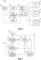
- a yaw control system 40a is illustrated for implementing embodiments of the invention.
- the system power 100 or backup power 102 may be coupled with the wind turbine controller 80 or yaw controller 70 depending on where the functionality of the invention is implemented.
- the invention may be implemented through operation of the wind turbine controller or through a separate yaw controller 70.
- FIG. 6 illustrates control of the various yaw motors 46, by a separate yaw controller 70, but a person of ordinary skill in the art would understand that such yaw motors 46 may also be directly coupled with the wind turbine controller 80 for control thereby if the yaw controller functionality is implemented in the wind turbine controller.
- the brake elements 52 of the yaw system are separated from the grid or other power system 100, 102 used to power the yaw system.
- yaw control 40a as illustrated in FIG. 6 , provides a separate brake power supply 110 coupled with the brakes 52 of each of the yaw motors 46.
- the brakes 52 are powered independently of the system power or grid power which may be used to power the various yaw motors 46.
- the brakes 52 are powered separately by a common voltage stabilized power supply 110, such as, for example, a 24 volt DC power supply.
- Such a stabilized power supply 110 would be able to keep the voltage power signal to the brakes 52 within a stable range of approximately +/-10% for controlling the brakes during extreme voltage variations on the grid. In that way, the invention ensures that the brakes will disengage properly during extreme grid voltage variations. As such, the motor torque used to provide the yawing function will not have to overcome the brake torque as in current systems wherein the brake functionality is detrimentally affected by the grid variations. This leads to improved yaw capacity and also longer wear lives with respect to the brake 52 as well as the yaw motors 46. Furthermore, the yaw motors and various other components of the yaw system are not overloaded.
- the yaw control system including yaw controller 70, 80 is configured to control the yawing function based upon the ability to provide sufficient braking.
- a brake control signal 112 is provided to the controller 70, 80 that is reflective of the power supply 110.
- the signal 112 may be reflective of whether the brake power supply is operational.
- the brake power supply 110 is coupled to the yaw controller 70, 80 through a suitable connection for providing brake control signal 112.
- the appropriate controller 70, 80 monitors or evaluates the brake power supply 110 and/or control signal 112 or other data regarding the operation of the brake elements 52 as related to the yawing function. Based on that evaluation, such as a determination that the brake power supply 110 is not operational, the yaw controller 70, 80 would selectively delay the yaw function and prevent the yaw motors 46 from operating.
- the yaw control system of the invention would monitor grid conditions, such as through control signal 108, and would also monitor the yaw components such as through the brake power supply 110 and control signal 112, in order to make decisions with respect to when the yawing function would be appropriate or whether it should be delayed.
- the present invention selectively delays yawing in scenarios wherein extreme voltage and frequency situations may occur.
- the yawing function may be selectively delayed or otherwise prevented if the brakes 52 would not operate properly, such as upon the failure of brake power supply 110.
- an embodiment of the invention may only implement monitoring of the brake power supply 110 in affecting or delaying the yawing function, independently of grid variation.
- a backup power unit 102 might be coupled with various of the elements, including a wind turbine controller 80 or separate yaw controller 70 as illustrated.
- the backup power system 102 might be an external backup generator.
- the wind turbine controller 80 or controller 70 as described herein will include the necessary elements, such as a processor and memory, for running a control program to effect the present invention as understood by a person of ordinary skill in the art.
- Such memory for example may store suitable grid variation ranges against which a control signal 105,108 from the grid may be compared to see if the yaw function should be delayed as described herein.
- suitable grid variation ranges reflective of variations from a nominal grid parameter, such as grid voltage might be stored for use in the control scheme to compare against one or more control signals.
- one exemplary range might be -13% to +16% with respect to the nominal grid voltage for evaluating if the yaw function should be executed or delayed. Other ranges might also be used.
- FIG.7 illustrates one embodiment of the program flow of the yaw controller 70,80 in accordance with an embodiment of the invention.
- a grid condition may be evaluated, and the protocol may start at block 120.
- the voltage is evaluated.
- the grid frequency might also be evaluated based on a control signal 108 and compared against a suitable range or other metric.
- the control signal 108 received by the controller 70, 80 might be evaluated. For example, based on the sensed grid voltage it might be evaluated or tested by being compared against a range, such as -13% to +16% with respect to a nominal grid voltage, as noted. If the grid voltage is not within or is outside the range, there may be a delay in the yaw function at 126 and the controller would not operate the yaw motors to move the nacelle.
- the comparison of the control signal against a suitable range of conditions may be done periodically. For example, based on a loop path 127, the system may check the grid voltage in relation to the acceptable range on a periodic or loop basis. Once the grid voltage is in an acceptable range, then the yaw function may follow path 129, for example, and may proceed at 130, as discussed herein.
- a time limit on the delay of the yaw function may be implemented. If a time limit function is implemented, following a determination that the grid voltage is outside of an acceptable range at 122, a further determination could be made of whether the time limit has elapsed at 124. If the time limit has not been reached, the yaw function delay would proceed at 126. As the control loop of the yaw function delay progresses in loop 127, the time limit could be consecutively checked if the grid voltage remains out of the acceptable range. If the time limit has been reached or a set amount of time has elapsed, then the yaw function might proceed at 126 despite the grid voltage being out of an acceptable range as shown in FIG. 7 .
- the functionality of the controller 70, 80 and the evaluation of the brake power supply at block 128 may take place independently in a separate control flow from the evaluation of the grid variation.
- the functionality of the brakes through their supply of power could be evaluated at 128, such as be evaluating the control signal 112 reflective of the power supply 110. If the power supply is not operational, as reflected by the control signal 112, the brakes would not have power. In such a scenario, the yaw function could be delayed at 126. It will be understood by a person of ordinary skill in the art that the functionality of FIG. 7 may be implemented in the controller 70,80 as necessary to achieve the noted control of the yaw function.
Landscapes
- Engineering & Computer Science (AREA)
- Life Sciences & Earth Sciences (AREA)
- Sustainable Development (AREA)
- Sustainable Energy (AREA)
- Chemical & Material Sciences (AREA)
- Combustion & Propulsion (AREA)
- Mechanical Engineering (AREA)
- General Engineering & Computer Science (AREA)
- Wind Motors (AREA)
Claims (14)
- Windkraftanlage (10), die eine Gondel (14) einschließt, die beweglich auf einem Turm (12) montiert ist, um elektrische Energie an ein Stromnetz (104) bereitzustellen, wobei die Windkraftanlage (10) Folgendes umfasst:ein Giersystem, das mindestens einen Giermotor (46) einschließt, der betreibbar ist, um eine Gierfunktion für die Windkraftanlage (10) bereitzustellen und die Gondel (14) in Bezug auf den Turm (12) zu bewegen;eine mit dem Giersystem gekoppelte Steuereinheit (70, 80) zum Steuern des Betriebs des mindestens einen Giermotors (46) in der Gierfunktion;ein an die Steuereinheit (70, 80) bereitgestelltes Steuersignal (108), das einen Netzzustand eines Stromnetzes (10) widerspiegelt;wobei die Steuereinheit (70, 80) dazu konfiguriert ist, das Steuersignal (108) auszuwerten und die Gierfunktion basierend auf dem Steuersignal (108) selektiv zu verzögern und nach Ablauf der Verzögerung mit der Gierfunktion fortzufahren, dadurch gekennzeichnet, dass die Steuereinheit (70, 80) eine Zeitgrenze einschließt, und wobei die Steuereinheit (70, 80) weiter dazu konfiguriert ist, zu bestimmen, ob die Verzögerung der Gierfunktion die Zeitgrenze überschreitet, und mit der Gierfunktion fortzufahren, wenn die Verzögerung die Zeitgrenze überschreitet.
- Windkraftanlage (10) nach Anspruch 1, wobei die Steuereinheit (70, 80) einen Netzvariationsbereich für den Betrieb einschließt, der mit dem Stromnetz (104) verknüpft ist, wobei die Steuereinheit (70, 80) das Steuersignal (108) mit dem Netzvariationsbereich vergleicht und die Gierfunktion basierend auf dem Vergleich selektiv verzögert.
- Windkraftanlage (10) nach Anspruch 2, wobei die Gierfunktion verzögert wird, wenn das Steuersignal (108) außerhalb des Netzvariationsbereichs liegt.
- Windkraftanlage (10) nach einem der vorstehenden Ansprüche, wobei das an die Steuereinheit (70, 80) bereitgestellte Steuersignal (108) eine Netzspannung des Stromnetzes (104) widerspiegelt.
- Windkraftanlage (10) nach einem der vorstehenden Ansprüche, wobei die Steuereinheit (70, 80) bei einer Bestimmung, dass das Steuersignal (108) außerhalb des Netzvariationsbereichs liegt, weiter dazu konfiguriert ist, das Steuersignal (108) im Zeitverlauf regelmäßig mit dem Netzvariationsbereich zu vergleichen.
- Windkraftanlage (10) nach einem der vorstehenden Ansprüche, wobei die Gierfunktion selektiv um eine voreingestellte Verzögerungszeit verzögert wird.
- Windkraftanlage (10) nach einem der vorstehenden Ansprüche, wobei das Giersystem weiter mindestens eine Bremse (52) zum Bremsen des mindestens einen Giermotors (46) und eine separate Stromversorgung (110) für die Bremse einschließt, wobei der Steuereinheit (70, 80) ein Bremssteuersignal (112) bereitgestellt wird, das die Stromversorgung für die Bremse widerspiegelt, und wobei die Steuereinheit (70, 80) weiter zum Auswerten des Bremssteuersignals (112) und zum selektiven Verzögern der Gierfunktion basierend auf dem Bremssteuersignal (112) konfiguriert ist.
- Windkraftanlage (10) nach Anspruch 7, wobei das Bremssteuersignal (112) widerspiegelt, ob die Bremsstromversorgung (110) betriebsbereit ist, wobei die Steuereinheit (70, 80) weiter dazu konfiguriert ist, das Bremssteuersignal (112) auszuwerten und die Gierfunktion selektiv zu verzögern, wenn die Bremsstromversorgung (110) nicht betriebsbereit ist.
- Verfahren zum Steuern einer Windkraftanlage (10), die eine Gondel (14) aufweist, die beweglich auf einem Turm (12) montiert ist, um elektrische Energie an ein Stromnetz (104) bereitzustellen, wobei das Verfahren umfasst:Betreiben eines Giersystems, das mindestens einen Giermotor (46) einschließt, der betreibbar ist, um eine Gierfunktion für die Windkraftanlage (10) bereitzustellen und die Gondel (14) in Bezug auf den Turm (12) zu bewegen;Bereitstellen eines bereitgestellten Steuersignals (108), das einen Netzzustand eines Stromnetzes (104) widerspiegelt;Auswerten des Steuersignals (108) und selektives Verzögern der Gierfunktion basierend auf dem Steuersignal und Fortfahren mit der Gierfunktion nach Ablauf der Verzögerung, dadurch gekennzeichnet, dass die Steuereinheit (70, 80) eine Zeitgrenze einschließt und die Steuereinheit (70, 80) weiter dazu konfiguriert ist, zu bestimmen, ob die Verzögerung der Gierfunktion die Zeitgrenze überschreitet, und mit der Gierfunktion fortzufahren, wenn die Verzögerung die Zeitgrenze überschreitet.
- Verfahren nach Anspruch 9, das weiter Vergleichen des Steuersignals (108) mit einem Gittervariationsbereich und selektives Verzögern der Gierfunktion umfasst, wenn das Steuersignal (108) außerhalb des Gittervariationsbereichs liegt.
- Verfahren nach Anspruch 10, das weiter bei einer Bestimmung, dass das Steuersignal (108) außerhalb des Gittervariationsbereichs liegt, regelmäßiges Vergleichen des Steuersignals (108) im Zeitverlauf mit dem Gittervariationsbereich umfasst.
- Verfahren nach einem der Ansprüche 9-11, wobei das Giersystem weiter mindestens eine Bremse (52) zum Zusammenwirken mit dem mindestens einen Giermotor (46) und eine separate Stromversorgung (110) für die Bremse einschließt, wobei das Verfahren weiter umfasst:
Bereitstellen eines Bremssteuersignals (112), das die Stromversorgung (110) für die Bremse widerspiegelt, und Auswerten des Bremssteuersignals (112) und selektives Verzögern der Gierfunktion basierend auf dem Bremssteuersignal (112). - Verfahren nach Anspruch 12, wobei das Bremssteuersignal (112) widerspiegelt, ob die Bremsstromversorgung (110) betriebsbereit ist, wobei das Verfahren weiter Auswerten des Bremssteuersignals (112) und selektives Verzögern der Gierfunktion umfasst, wenn die Bremsstromversorgung (110) nicht betriebsbereit ist.
- Steuereinheit (70, 80) zum Steuern der Gierfunktion einer Windkraftanlage (10), die eine beweglich auf einem Turm (12) montierte Gondel (14) zum Bereitstellen elektrischer Energie an ein Stromnetz (104) und ein Giersystem einschließt, das mindestens einen Giermotor (46) einschließt, der betreibbar ist, um die Gondel (14) in Bezug auf den Turm (12) zu bewegen, wobei die Steuereinheit (70, 80) konfiguriert ist zum:Steuern des Betriebs des mindestens einen Giermotors (46) in der Gierfunktion zum Bewegen der Gondel (14);Empfangen eines Steuersignals (108), das einen Netzzustand eines Stromnetzes (104) widerspiegelt; undAuswerten des Steuersignals (108) und selektives Verzögern der Gierfunktion basierend auf dem Steuersignal (108) und Fortfahren mit der Gierfunktion nach Ablauf der Verzögerung, dadurch gekennzeichnet, dass die Steuereinheit (70, 80) eine Zeitgrenze einschließt und die Steuereinheit (70, 80) weiter dazu konfiguriert ist, zu bestimmen, ob die Verzögerung der Gierfunktion die Zeitgrenze überschreitet, und mit der Gierfunktion fortzufahren, wenn die Verzögerung die Zeitgrenze überschreitet.
Applications Claiming Priority (2)
| Application Number | Priority Date | Filing Date | Title |
|---|---|---|---|
| DKPA202070305 | 2020-05-12 | ||
| PCT/DK2021/050145 WO2021228337A1 (en) | 2020-05-12 | 2021-05-06 | Yaw system with yaw control based on control signal |
Publications (3)
| Publication Number | Publication Date |
|---|---|
| EP4150208A1 EP4150208A1 (de) | 2023-03-22 |
| EP4150208B1 true EP4150208B1 (de) | 2025-07-02 |
| EP4150208C0 EP4150208C0 (de) | 2025-07-02 |
Family
ID=76076187
Family Applications (1)
| Application Number | Title | Priority Date | Filing Date |
|---|---|---|---|
| EP21727362.2A Active EP4150208B1 (de) | 2020-05-12 | 2021-05-06 | Giersystem mit giersteuerung auf der basis eines steuersignals |
Country Status (5)
| Country | Link |
|---|---|
| US (1) | US12044211B2 (de) |
| EP (1) | EP4150208B1 (de) |
| CN (1) | CN115836158A (de) |
| ES (1) | ES3035864T3 (de) |
| WO (1) | WO2021228337A1 (de) |
Families Citing this family (1)
| Publication number | Priority date | Publication date | Assignee | Title |
|---|---|---|---|---|
| EP4150208B1 (de) | 2020-05-12 | 2025-07-02 | Vestas Wind Systems A/S | Giersystem mit giersteuerung auf der basis eines steuersignals |
Family Cites Families (13)
| Publication number | Priority date | Publication date | Assignee | Title |
|---|---|---|---|---|
| US6921985B2 (en) | 2003-01-24 | 2005-07-26 | General Electric Company | Low voltage ride through for wind turbine generators |
| ES2561842T3 (es) * | 2009-06-29 | 2016-03-01 | Vestas Wind Systems A/S | Turbina eólica que proporciona soporte a la red de distribución |
| US8022566B2 (en) * | 2010-06-23 | 2011-09-20 | General Electric Company | Methods and systems for operating a wind turbine |
| US20130270823A1 (en) * | 2012-04-17 | 2013-10-17 | Clipper Windpower, Llc | Method for Enhancing Low Voltage Ride Through Capability on a Wind Turbine |
| US9631608B2 (en) * | 2012-06-12 | 2017-04-25 | Vestas Wind Systems A/S | Wind-power-plant control upon low-voltage grid faults |
| US9677540B2 (en) * | 2012-11-29 | 2017-06-13 | General Electric Company | System and method for providing yaw backup to a wind farm |
| US10107260B2 (en) * | 2015-11-19 | 2018-10-23 | General Electric Company | Wind turbine auxiliary circuit control |
| CN107345507B (zh) * | 2016-05-05 | 2019-03-15 | 中国船舶重工集团海装风电股份有限公司 | 一种偏航速度检测的方法及系统 |
| JP6783110B2 (ja) * | 2016-10-06 | 2020-11-11 | 株式会社日立製作所 | 予兆診断装置及びそれを有する発電装置制御システム |
| US10519933B2 (en) | 2017-04-24 | 2019-12-31 | General Electric Company | Method of operating a wind turbine system including an energy storage system |
| DK3450746T3 (da) * | 2017-09-05 | 2021-05-10 | Siemens Gamesa Renewable Energy As | Vindmølle |
| US10662923B2 (en) | 2017-09-29 | 2020-05-26 | General Electric Company | Contingency autonomous yaw control for a wind turbine |
| EP4150208B1 (de) | 2020-05-12 | 2025-07-02 | Vestas Wind Systems A/S | Giersystem mit giersteuerung auf der basis eines steuersignals |
-
2021
- 2021-05-06 EP EP21727362.2A patent/EP4150208B1/de active Active
- 2021-05-06 US US17/925,240 patent/US12044211B2/en active Active
- 2021-05-06 CN CN202180049287.5A patent/CN115836158A/zh active Pending
- 2021-05-06 ES ES21727362T patent/ES3035864T3/es active Active
- 2021-05-06 WO PCT/DK2021/050145 patent/WO2021228337A1/en not_active Ceased
Also Published As
| Publication number | Publication date |
|---|---|
| EP4150208A1 (de) | 2023-03-22 |
| US20230228244A1 (en) | 2023-07-20 |
| CN115836158A (zh) | 2023-03-21 |
| US12044211B2 (en) | 2024-07-23 |
| ES3035864T3 (en) | 2025-09-10 |
| WO2021228337A1 (en) | 2021-11-18 |
| EP4150208C0 (de) | 2025-07-02 |
Similar Documents
| Publication | Publication Date | Title |
|---|---|---|
| EP2108825B1 (de) | System und Verfahren zur Reduzierung der Rotorbelastung in einer Windturbine bei Erkennung eines Schaufelneigungsfehlers oder eines Drehmomentverlustes | |
| EP3276165B1 (de) | Batterieunterstütztes bremssystem für eine windturbine | |
| EP2365215B1 (de) | Drehzahlsteuerung einer Windturbine basierend auf der Rotorbeschleunigung | |
| CN101487446B (zh) | 速度受控的倾斜系统 | |
| US7772713B2 (en) | Method and system for controlling a wind turbine | |
| EP3597905B1 (de) | System und verfahren zur erkennung eines neigungsfehlers in einer windturbine mittels spannungs-, strom-, drehmoment- oder kraftüberwachung | |
| EP1612414B1 (de) | Verfahren sowie Vorrichtung zur Reduktion der Rotorbelastungen einer Windenergieanlage | |
| EP2472104B1 (de) | Verfahren und System zum Bremsen einer Windturbine | |
| US8922039B2 (en) | Wind turbine and a method for powering one or more hydraulic pitch actuators | |
| CN1997823A (zh) | 控制风轮机叶片的倾斜速度的方法及其控制系统 | |
| US20230151797A1 (en) | Method for controlling a wind turbine system in relation to braking of the yaw system | |
| US20140203560A1 (en) | Wind turbine and method for adjusting rotor blade pitch angle in wind turbine | |
| US11732689B2 (en) | Wind turbine drive control device, wind turbine power supply device, wind power generation device, and control method | |
| CN114930016B (zh) | 偏航管理 | |
| US12460618B2 (en) | Wind turbine yawing system with multiple mechanical braking levels | |
| EP2754888B1 (de) | Verfahren und vorrichtung zum betreiben einer windturbine | |
| CN103998774A (zh) | 用于操作风力涡轮机的方法 | |
| EP4325047B1 (de) | Lastabhängige autonome giersteuerung für eine windturbine | |
| EP3788258B1 (de) | System und verfahren zur verbesserten überdrehzahlüberwachung einer windturbine mit betrieb bei verringerter rotordrehzahl | |
| US12044211B2 (en) | Yaw system with yaw control based on control signal | |
| US10316822B2 (en) | System and method for improved overspeed monitoring of a wind turbine operating at reduced rotor speeds | |
| EP3597906B1 (de) | System und verfahren zur reduzierung der belastungen einer windturbine, wenn ein rotorblatt festsitzt |
Legal Events
| Date | Code | Title | Description |
|---|---|---|---|
| STAA | Information on the status of an ep patent application or granted ep patent |
Free format text: STATUS: UNKNOWN |
|
| STAA | Information on the status of an ep patent application or granted ep patent |
Free format text: STATUS: THE INTERNATIONAL PUBLICATION HAS BEEN MADE |
|
| PUAI | Public reference made under article 153(3) epc to a published international application that has entered the european phase |
Free format text: ORIGINAL CODE: 0009012 |
|
| STAA | Information on the status of an ep patent application or granted ep patent |
Free format text: STATUS: REQUEST FOR EXAMINATION WAS MADE |
|
| 17P | Request for examination filed |
Effective date: 20221208 |
|
| AK | Designated contracting states |
Kind code of ref document: A1 Designated state(s): AL AT BE BG CH CY CZ DE DK EE ES FI FR GB GR HR HU IE IS IT LI LT LU LV MC MK MT NL NO PL PT RO RS SE SI SK SM TR |
|
| DAV | Request for validation of the european patent (deleted) | ||
| DAX | Request for extension of the european patent (deleted) | ||
| GRAP | Despatch of communication of intention to grant a patent |
Free format text: ORIGINAL CODE: EPIDOSNIGR1 |
|
| STAA | Information on the status of an ep patent application or granted ep patent |
Free format text: STATUS: GRANT OF PATENT IS INTENDED |
|
| INTG | Intention to grant announced |
Effective date: 20250218 |
|
| GRAS | Grant fee paid |
Free format text: ORIGINAL CODE: EPIDOSNIGR3 |
|
| GRAA | (expected) grant |
Free format text: ORIGINAL CODE: 0009210 |
|
| STAA | Information on the status of an ep patent application or granted ep patent |
Free format text: STATUS: THE PATENT HAS BEEN GRANTED |
|
| AK | Designated contracting states |
Kind code of ref document: B1 Designated state(s): AL AT BE BG CH CY CZ DE DK EE ES FI FR GB GR HR HU IE IS IT LI LT LU LV MC MK MT NL NO PL PT RO RS SE SI SK SM TR |
|
| REG | Reference to a national code |
Ref country code: GB Ref legal event code: FG4D |
|
| REG | Reference to a national code |
Ref country code: CH Ref legal event code: EP |
|
| REG | Reference to a national code |
Ref country code: DE Ref legal event code: R096 Ref document number: 602021033343 Country of ref document: DE |
|
| REG | Reference to a national code |
Ref country code: IE Ref legal event code: FG4D |
|
| U01 | Request for unitary effect filed |
Effective date: 20250716 |
|
| U07 | Unitary effect registered |
Designated state(s): AT BE BG DE DK EE FI FR IT LT LU LV MT NL PT RO SE SI Effective date: 20250723 |
|
| REG | Reference to a national code |
Ref country code: ES Ref legal event code: FG2A Ref document number: 3035864 Country of ref document: ES Kind code of ref document: T3 Effective date: 20250910 |
|
| PG25 | Lapsed in a contracting state [announced via postgrant information from national office to epo] |
Ref country code: IS Free format text: LAPSE BECAUSE OF FAILURE TO SUBMIT A TRANSLATION OF THE DESCRIPTION OR TO PAY THE FEE WITHIN THE PRESCRIBED TIME-LIMIT Effective date: 20251102 |
|
| PG25 | Lapsed in a contracting state [announced via postgrant information from national office to epo] |
Ref country code: NO Free format text: LAPSE BECAUSE OF FAILURE TO SUBMIT A TRANSLATION OF THE DESCRIPTION OR TO PAY THE FEE WITHIN THE PRESCRIBED TIME-LIMIT Effective date: 20251002 |
|
| PG25 | Lapsed in a contracting state [announced via postgrant information from national office to epo] |
Ref country code: HR Free format text: LAPSE BECAUSE OF FAILURE TO SUBMIT A TRANSLATION OF THE DESCRIPTION OR TO PAY THE FEE WITHIN THE PRESCRIBED TIME-LIMIT Effective date: 20250702 |
|
| PG25 | Lapsed in a contracting state [announced via postgrant information from national office to epo] |
Ref country code: GR Free format text: LAPSE BECAUSE OF FAILURE TO SUBMIT A TRANSLATION OF THE DESCRIPTION OR TO PAY THE FEE WITHIN THE PRESCRIBED TIME-LIMIT Effective date: 20251003 |
|
| PG25 | Lapsed in a contracting state [announced via postgrant information from national office to epo] |
Ref country code: CZ Free format text: LAPSE BECAUSE OF FAILURE TO SUBMIT A TRANSLATION OF THE DESCRIPTION OR TO PAY THE FEE WITHIN THE PRESCRIBED TIME-LIMIT Effective date: 20250702 |
|
| PG25 | Lapsed in a contracting state [announced via postgrant information from national office to epo] |
Ref country code: PL Free format text: LAPSE BECAUSE OF FAILURE TO SUBMIT A TRANSLATION OF THE DESCRIPTION OR TO PAY THE FEE WITHIN THE PRESCRIBED TIME-LIMIT Effective date: 20250702 |
|
| PG25 | Lapsed in a contracting state [announced via postgrant information from national office to epo] |
Ref country code: RS Free format text: LAPSE BECAUSE OF FAILURE TO SUBMIT A TRANSLATION OF THE DESCRIPTION OR TO PAY THE FEE WITHIN THE PRESCRIBED TIME-LIMIT Effective date: 20251002 |
|
| PG25 | Lapsed in a contracting state [announced via postgrant information from national office to epo] |
Ref country code: SM Free format text: LAPSE BECAUSE OF FAILURE TO SUBMIT A TRANSLATION OF THE DESCRIPTION OR TO PAY THE FEE WITHIN THE PRESCRIBED TIME-LIMIT Effective date: 20250702 |
|
| PGFP | Annual fee paid to national office [announced via postgrant information from national office to epo] |
Ref country code: GB Payment date: 20260309 Year of fee payment: 6 |
|
| PG25 | Lapsed in a contracting state [announced via postgrant information from national office to epo] |
Ref country code: SK Free format text: LAPSE BECAUSE OF FAILURE TO SUBMIT A TRANSLATION OF THE DESCRIPTION OR TO PAY THE FEE WITHIN THE PRESCRIBED TIME-LIMIT Effective date: 20250702 |
|
| PLBE | No opposition filed within time limit |
Free format text: ORIGINAL CODE: 0009261 |
|
| STAA | Information on the status of an ep patent application or granted ep patent |
Free format text: STATUS: NO OPPOSITION FILED WITHIN TIME LIMIT |