EP4151391A1 - Imprimante pbf comportant un système de circulation de poudre - Google Patents
Imprimante pbf comportant un système de circulation de poudre Download PDFInfo
- Publication number
- EP4151391A1 EP4151391A1 EP21461593.2A EP21461593A EP4151391A1 EP 4151391 A1 EP4151391 A1 EP 4151391A1 EP 21461593 A EP21461593 A EP 21461593A EP 4151391 A1 EP4151391 A1 EP 4151391A1
- Authority
- EP
- European Patent Office
- Prior art keywords
- powder
- screw conveyor
- container
- unused
- printing
- Prior art date
- Legal status (The legal status is an assumption and is not a legal conclusion. Google has not performed a legal analysis and makes no representation as to the accuracy of the status listed.)
- Withdrawn
Links
Images


Classifications
-
- B—PERFORMING OPERATIONS; TRANSPORTING
- B29—WORKING OF PLASTICS; WORKING OF SUBSTANCES IN A PLASTIC STATE IN GENERAL
- B29C—SHAPING OR JOINING OF PLASTICS; SHAPING OF MATERIAL IN A PLASTIC STATE, NOT OTHERWISE PROVIDED FOR; AFTER-TREATMENT OF THE SHAPED PRODUCTS, e.g. REPAIRING
- B29C64/00—Additive manufacturing, i.e. manufacturing of three-dimensional [3D] objects by additive deposition, additive agglomeration or additive layering, e.g. by 3D printing, stereolithography or selective laser sintering
- B29C64/10—Processes of additive manufacturing
- B29C64/141—Processes of additive manufacturing using only solid materials
- B29C64/153—Processes of additive manufacturing using only solid materials using layers of powder being selectively joined, e.g. by selective laser sintering or melting
-
- B—PERFORMING OPERATIONS; TRANSPORTING
- B22—CASTING; POWDER METALLURGY
- B22F—WORKING METALLIC POWDER; MANUFACTURE OF ARTICLES FROM METALLIC POWDER; MAKING METALLIC POWDER; APPARATUS OR DEVICES SPECIALLY ADAPTED FOR METALLIC POWDER
- B22F10/00—Additive manufacturing of workpieces or articles from metallic powder
- B22F10/20—Direct sintering or melting
- B22F10/28—Powder bed fusion, e.g. selective laser melting [SLM] or electron beam melting [EBM]
-
- B—PERFORMING OPERATIONS; TRANSPORTING
- B22—CASTING; POWDER METALLURGY
- B22F—WORKING METALLIC POWDER; MANUFACTURE OF ARTICLES FROM METALLIC POWDER; MAKING METALLIC POWDER; APPARATUS OR DEVICES SPECIALLY ADAPTED FOR METALLIC POWDER
- B22F10/00—Additive manufacturing of workpieces or articles from metallic powder
- B22F10/70—Recycling
- B22F10/73—Recycling of powder
-
- B—PERFORMING OPERATIONS; TRANSPORTING
- B29—WORKING OF PLASTICS; WORKING OF SUBSTANCES IN A PLASTIC STATE IN GENERAL
- B29C—SHAPING OR JOINING OF PLASTICS; SHAPING OF MATERIAL IN A PLASTIC STATE, NOT OTHERWISE PROVIDED FOR; AFTER-TREATMENT OF THE SHAPED PRODUCTS, e.g. REPAIRING
- B29C64/00—Additive manufacturing, i.e. manufacturing of three-dimensional [3D] objects by additive deposition, additive agglomeration or additive layering, e.g. by 3D printing, stereolithography or selective laser sintering
- B29C64/30—Auxiliary operations or equipment
- B29C64/357—Recycling
-
- B—PERFORMING OPERATIONS; TRANSPORTING
- B33—ADDITIVE MANUFACTURING TECHNOLOGY
- B33Y—ADDITIVE MANUFACTURING, i.e. MANUFACTURING OF THREE-DIMENSIONAL [3D] OBJECTS BY ADDITIVE DEPOSITION, ADDITIVE AGGLOMERATION OR ADDITIVE LAYERING, e.g. BY 3D PRINTING, STEREOLITHOGRAPHY OR SELECTIVE LASER SINTERING
- B33Y10/00—Processes of additive manufacturing
-
- B—PERFORMING OPERATIONS; TRANSPORTING
- B33—ADDITIVE MANUFACTURING TECHNOLOGY
- B33Y—ADDITIVE MANUFACTURING, i.e. MANUFACTURING OF THREE-DIMENSIONAL [3D] OBJECTS BY ADDITIVE DEPOSITION, ADDITIVE AGGLOMERATION OR ADDITIVE LAYERING, e.g. BY 3D PRINTING, STEREOLITHOGRAPHY OR SELECTIVE LASER SINTERING
- B33Y30/00—Apparatus for additive manufacturing; Details thereof or accessories therefor
-
- Y—GENERAL TAGGING OF NEW TECHNOLOGICAL DEVELOPMENTS; GENERAL TAGGING OF CROSS-SECTIONAL TECHNOLOGIES SPANNING OVER SEVERAL SECTIONS OF THE IPC; TECHNICAL SUBJECTS COVERED BY FORMER USPC CROSS-REFERENCE ART COLLECTIONS [XRACs] AND DIGESTS
- Y02—TECHNOLOGIES OR APPLICATIONS FOR MITIGATION OR ADAPTATION AGAINST CLIMATE CHANGE
- Y02P—CLIMATE CHANGE MITIGATION TECHNOLOGIES IN THE PRODUCTION OR PROCESSING OF GOODS
- Y02P10/00—Technologies related to metal processing
- Y02P10/25—Process efficiency
Definitions
- the disclosed invention relates to a Powder Bed Fusion (PBF) printer with a powder circulation system.
- PPF Powder Bed Fusion
- Powder Bed Fusion (PBF) 3D printing technique enables the manufacturing of a vast array of geometrically complex products using an energy source, such as laser or electron beams, to fuse powder particles layer-by-layer, therefore forming a solid part.
- an energy source such as laser or electron beams
- PBF 3D printers There are different known techniques for printing 3D objects, by the PBF additive manufacturing process, for which different types of PBF 3D printers are used such as: Selective Laser Sintering (SLS) in which plastic powder is sintered, Selective Laser Melting (SLM) and Electron Beam Melting (EBM) in which metal powder is melted.
- SLS Selective Laser Sintering
- SLM Selective Laser Melting
- EBM Electron Beam Melting
- the Selective Laser Sintering (SLS) technique uses a laser as an energy source to sinter a powdered material (typically polyamide), aiming the laser automatically at points in space defined by a 3D model, thereby binding the material together to create a solid structure (a three-dimensional object).
- a powdered material typically polyamide
- a conventional SLS printer comprises a support (called a "bed”) for a printed object on which a recoating roller spreads a thin layer of powder which is subsequently sintered by means of a laser according to layers sliced from a 3D model file.
- a platform for example a piston
- the bed moves down by a distance equal to a thickness of a single layer and the process repeats until the last layer of the printed object is formed.
- the obtained three-dimensional object is cooled down and removed from an unsintered powder suspension.
- the unsintered powder can be used for the next printing process.
- a Chinese patent application CN111958971A discloses a powder feeding device for an SLS printer for manufacturing three-dimensional objects, comprising a powder storage groove, a powder feeding hopper, a powder feeding box, a powder feeding rotating shaft, a first gear, a second gear, a driving mechanism and a control system.
- the powder storage groove is orderly provided with at least one first feeding position switch and a first discharging position switch from the top to the bottom.
- the bottom of the powder feeding hopper is provided with a butterfly valve.
- the control system is controlling whether the powder falls to the powder storage groove.
- One end of the powder feeding rotating shaft is connected with the first gear and the second gear is connected with the driving mechanism, wherein the first gear is engaged with the second gear.
- the driving mechanism actuates the powder feeding rotating shaft providing the powder from the powder storing groove to fall to the powder feeding box and falling to the powder feeding position through the outlet of the powder feeding box.
- the abovementioned device does not provide a system for recirculating the excessive powder back to the powder feeding hopper.
- a Chinese patent application CN112387985A discloses a closed-loop powder circulation system used for additive manufacturing equipment, in particular for SLS printers, and a method of filtering the powder.
- the system comprises a powder storage tank, a fan, a separating tank, a vibration sieve, a controller and a powder returning tank.
- the controller receives the powder feeding instruction it turns on the fan, so that the powder from the powder storage tank is conveyed to at least one powder feeding tank under the protection of the inert gas.
- the controller receives the powder returning instruction, it turns on the fan so that the powder from the powder returning tank and/or at least one powder overflowing cylinder is conveyed to the separating tank under the protection of the inert gas.
- the invention relates to a powder bed fusion (PBF) printer, comprising a housing with a printing chamber; an energy source; a printing bed for supporting a printed object; a main powder container for storing a powder; and a powder distribution unit for distributing a layer of the powder on the previously processed layer.
- the printer further comprises a mechanical powder circulation system comprising a screw conveyor mechanism for transferring the unused powder from the printing chamber to the printing bed.
- the powder bed fusion printer with the mechanical circulation system allows to recirculate the unused powder back to the printing chamber.
- Use of the mechanical powder circulation system allows to maintain proper printing condition in the printing chamber, in particular concerning the temperature in the printing chamber which needs to be constant during the printing process. This is In contrast to prior art solutions of circulation systems, wherein powder is circulated within a stream of flowing air, which negatively influences the conditions in the printing chamber - this requires application of sophisticated temperature control systems for maintaining a constant temperature in the printing chamber.
- the screw conveyor mechanism of the mechanical powder circulation system does not cause air flow that could affect the temperature within the printing chamber.
- the printing chamber and the mechanical powder circulation system with the screw conveyor mechanism can be hermetically sealed from the outer environment to further increase the stability of conditions within the printing chamber.
- the energy source used for processing the powder, in particular sintering or melting may for example have a form of a laser source (in an SLS printer) or electron beam emitter (gun) (in a SLM or EBM printer).
- the mechanical powder circulation system can be further configured to transport the powder from the main powder container to the printing bed. Adding fresh powder to unused powder at the screw conveyor mechanism facilitates mixing of the powders as they are transported along the screw conveyor.
- the unused powder is resupplied with fresh powder only in the amount needed to maintain substantially constant dosage of the powder into the printing chamber. It means that in the first place the unused powder form the previous cycle is resupplied to the printing chamber. It prevents the prolonged accumulation of the unused powder in the system, as the quality and physical properties of the powder which remains unused for a longer time might decrease, as it is prone to moisture absorption and agglomeration.
- the mechanical powder circulation system may comprise a horizontal screw conveyor configured to transport powder to a powder transfer chamber and a vertical screw conveyor configured to transport powder from the powder transfer chamber wherein the horizontal screw conveyor is coupled to the vertical screw conveyor by means of the powder transfer chamber.
- Application of the horizontal screw conveyor and the vertical screw conveyor (instead of for example an inclined transport conveyor) allows to save space inside the printing machine.
- An outlet of the main powder container can be located above the horizontal screw conveyor.
- the mechanical powder circulation system may further comprise a secondary powder container for depositing the powder in front of the powder distribution unit, wherein the secondary powder container is located above the printing bed and wherein the vertical screw conveyor is configured to transfer the powder from the powder transfer chamber to the secondary powder container.
- the main powder container may be positioned in a location which is more convenient for its refilling with powder. This allows positioning the main powder container much lower than the secondary powder container, almost at a floor level, therefore the user does not have to lift up heavy boxes with powder at a great height in order to refill the printing machine.
- the mechanical powder circulation system may further comprise a first unused powder chute for transferring the unused powder from the first side of the printing chamber to the horizontal screw conveyor, wherein an outlet of the first unused powder chute is located in front of the outlet of the main powder container.
- the average amount of unused powder (recovered from the printing chamber) used during the printing process shall be preferably between 70-90%, while the average amount of fresh powder used during the printing process shall be preferably between 30-10%.
- the mechanical powder circulation system may further comprise a second unused powder chute for transferring the unused powder from the second side of the printing chamber to the main powder container.
- the secondary powder container may comprise a powder level sensor configured to actuate the mechanical powder circulation system when the powder level in the secondary powder container is below a predefined threshold.
- the powder level sensor helps to maintain an optimal amount of powder in the secondary powder container.
- the powder level sensor prevents from overfilling the secondary powder container by stopping the mechanical powder circulation system when the powder level in the secondary powder container is above a predefined level and prevents powder shortages in the secondary powder container by actuating the mechanical powder circulation system when the powder level in the secondary powder container is below a predefined threshold.
- the powder level sensor may be a capacitive proximity sensor. This allows to control the mechanical circulation system by means of just a single sensor located at the secondary powder container. No further sophisticated control mechanisms are needed.
- the secondary powder container may comprise a vibrating unit for inducing vibrations to the powder located in the secondary powder container.
- the vibrating unit helps to prevent powder jamming or creation of so called "rat holes" in the secondary powder container. Therefore the amount of powder deposited in each printing cycle is maintained substantially at the constant level.
- the rotational speed of the vertical screw conveyor can be from 1.2 to 4 times greater than the rotational speed of the horizontal screw conveyor.
- Application of different rotational speed values for the vertical screw conveyor with respect to the horizontal screw conveyor prevents powder jamming in the powder transfer chamber. This is particularly useful if the physical parameters of the horizontal screw conveyor and the vertical screw conveyor, such as diameter, screw pitch are to be the same, and therefore the efficiency of the vertical screw conveyor is made greater than the efficiency of the horizontal screw conveyor by adjusting its rotational speed.
- the outlet of the main powder container may comprise a sieve and/or the outlet of the first unused powder chute may comprise a sieve.
- the sieves prevent any contaminations, such as melted powder or fragments of the printed part, from falling into the horizontal screw conveyor.
- the mechanical powder circulation system may further comprise a transfer chute located between an outlet of the vertical screw conveyor and the secondary powder container.
- the transfer chute allows for gravitational transferring of the powder from the vertical screw conveyor to the secondary powder container. During the transfer through the transfer chute the powder becomes loose again after it is transferred by the screw conveyors.
- the invention also relates to a method of printing by means of a PBF printer as described herein, comprising recirculating the unused powder from the printing chamber to the printing bed by the mechanical powder circulation system.
- the method may comprise the steps of: depositing a dose of powder from the secondary powder container in front of the powder distribution unit; forming a layer of powder on the previously processed layer by means of the powder distribution unit; collecting unused powder from the printing chamber by means of the first unused powder chute; transferring the collected unused powder by means of the horizontal screw conveyor to the powder transfer chamber and simultaneously collecting the powder from the main powder container to completely fill the end part of the horizontal screw conveyor and the powder transfer chamber; and transferring the powder from the powder transfer chamber to the secondary powder container.
- the method may further comprise the step of collecting the unused powder from the printing chamber to the main powder container by means of a second unused powder chute.
- the unused powder is automatically transferred back to the printing chamber. Therefore the operator does not need to manually remove the unused powder from the printing chamber. Thus the printing chamber remains hermetical and powder does not escape from the printing chamber. As a result it is easier to maintain clean work space around the printing machine, while at the same time operators have less contact with the powder (in particular the operators are less prone to inhaling the powder, due to its flour like consistency which is generally harmful).
- SLS Selective Laser Sintering
- SLM Selective Laser Melting
- EBM Electron Beam Melting
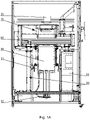
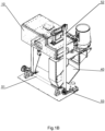
- the SLS printer as shown in Figs. 1A-1B , has a housing with a printing chamber 10.
- a laser 20 is used as an energy source for sintering.
- the object being printed is supported by a printing bed 30 to which powder is supplied by a powder distribution unit 60.
- the powder distribution unit 60 also called a recoater, is located in the printing chamber and distributes the powder as successive layers applied onto the previously processed (sintered) layer.
- the powder that is supplied to the printing bed is both fresh powder from a main powder container 40 and unused powder from the printing chamber, that is fed by a mechanical powder circulation system 50.
- the mechanical powder circulation system 50 is configured to transport both the unused powder and the fresh powder from the main powder container 40 to the printing bed 30.
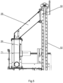
- the mechanical powder circulation system 50 comprises a horizontal screw conveyor 51 configured to transport powder to a powder transfer chamber 53 and a vertical screw conveyor 52 configured to transport powder from the powder transfer chamber 53. Therefore, the powder transfer chamber 53 functions to couple the horizontal screw conveyor 51 with the vertical screw conveyor 52 in terms of their powder transmission capability.
- the powder transfer chamber 53 should be supplied with powder in an amount such as to maintain its constant filling so that the vertical screw conveyor 52 can operate properly. Shortages of powder in the powder transfer chamber 53 (such that the powder transfer chamber is not completely filled with powder) should be avoided, such as not to cause problems in collecting the powder by the vertical screw conveyor 52 from the transfer chamber 53.
- the unused powder is transferred to the horizontal screw conveyor 51 from a first side of the printing chamber 10 by a first unused powder chute 55.
- An outlet 56 of the first unused powder chute 55 is located in front of an outlet 41 of the main powder container 40, i.e. upstream the path of powder transmission along the horizontal screw conveyor 51, so that the horizontal screw conveyor is fed first by the unused powder.
- the powder to the horizontal screw conveyor 51 is further supplied from the outlet 41 of the main powder container 40, that is located above the horizontal screw conveyor 51. Therefore, the powder from the main powder container 40 is transferred to the horizontal screw conveyor 51 by means of gravity and by rotating motion of the horizontal screw conveyor 51.
- a second unused powder chute 57 is provided for transferring the unused powder from the second side of the printing chamber 10 to the main powder container 40.
- a secondary powder container 54 is provided for depositing the powder in front of the powder distribution unit 60.
- the secondary powder container 54 is located above the printing bed 30 and the vertical screw conveyor 52 is configured to transfer the powder from the powder transfer chamber 53 to the secondary powder container 54.
- a transfer chute 58 is located between an outlet 59 of the vertical screw conveyor 52 and the secondary powder container 54.
- the secondary powder container 54 is smaller than the main powder container 40.
- the main powder container 40 is located almost at a floor level, much lower than the secondary powder container 54.
- the horizontal screw conveyor 51 is initially filled with the unused powder transferred by the first unused powder chute 55. Subsequently, the powder is transferred towards the outlet 41 region of the main powder container 40. The remaining space in the horizontal screw conveyor 51 is filled with the powder from the main powder container 40.
- the powder distribution unit 60 is moved from the first side of the printing chamber 10 to the second side of the printing chamber 10 and back to the first side of the printing chamber 10.
- a new layer of powder (usually having a thickness from 50 to 150 ⁇ m) is spread on the previously processed (for example sintered or melted) layer.
- the excess of the powder i.e. the unused powder
- the powder distribution unit 60 is pushed by the powder distribution unit 60 to both sides of the printing chamber 10, from where it is gravitationally transferred to the horizontal screw conveyor 51.
- the unused powder is transferred directly to the horizontal screw conveyor 51 by means of the first unused powder chute 55.
- the unused powder is transferred by the second unused powder chute 57 first to the main powder container 40 where it is mixed with a fresh powder and is further transferred to the horizontal screw conveyor 51.
- the vertical screw conveyor 52 rotates with a speed 2 times greater than the rotational speed of the horizontal screw conveyor 51.
- the conveyors 51, 52 have the same diameter and screw pitch.
- the secondary powder container 54 comprises a capacitive proximity sensor configured to sense the level of powder within the secondary powder container 54 and to actuate the mechanical powder circulation system 50 when the powder level in the secondary powder container 54 is below a predefined threshold.
- the secondary powder container 54 comprises a vibrating unit 71 for inducing vibrations to the powder located in the secondary powder container 54.
- the PBF printer as described herein operates as follows. First, a dose of powder is deposited from the secondary powder container 54 in front of the powder distribution unit 60. Then, a layer of powder is formed on the previously processed layer by means of the powder distribution unit 60. The unused powder is collected from the printing chamber 10 by means of the first unused powder chute 55. The unused powder from the printing chamber 10 is also collected to the main powder container 40 by means of a second unused powder chute 57. That collected unused powder is transferred by means of the horizontal screw conveyor 51 to the powder transfer chamber 53 and simultaneously powder is collected from the main powder container 40 to completely fill the end part of the horizontal screw conveyor 51 and the powder transfer chamber 53. Finally, the powder is transferred from the powder transfer chamber 53 to the secondary powder container 54.
- the unused powder is automatically transferred back to the printing chamber 10. Therefore the operator does not need to manually remove the unused powder from the printing chamber.
- the printing chamber remains hermetical and powder does not escape from the printing chamber. As a result it is easier to maintain clean work space around the printing machine, while at the same time operators have less contact with the powder (in particular the operators are less prone to inhaling the powder, due to its flour like consistency which is generally harmful).
- the mechanical circulation system may generally be controlled just by a single sensor located at the secondary powder container. No further sophisticated control mechanisms are needed.
Landscapes
- Engineering & Computer Science (AREA)
- Chemical & Material Sciences (AREA)
- Materials Engineering (AREA)
- Manufacturing & Machinery (AREA)
- Physics & Mathematics (AREA)
- Optics & Photonics (AREA)
- Life Sciences & Earth Sciences (AREA)
- Sustainable Development (AREA)
- Mechanical Engineering (AREA)
- Plasma & Fusion (AREA)
Priority Applications (1)
| Application Number | Priority Date | Filing Date | Title |
|---|---|---|---|
| EP21461593.2A EP4151391A1 (fr) | 2021-09-15 | 2021-09-15 | Imprimante pbf comportant un système de circulation de poudre |
Applications Claiming Priority (1)
| Application Number | Priority Date | Filing Date | Title |
|---|---|---|---|
| EP21461593.2A EP4151391A1 (fr) | 2021-09-15 | 2021-09-15 | Imprimante pbf comportant un système de circulation de poudre |
Publications (1)
| Publication Number | Publication Date |
|---|---|
| EP4151391A1 true EP4151391A1 (fr) | 2023-03-22 |
Family
ID=77801643
Family Applications (1)
| Application Number | Title | Priority Date | Filing Date |
|---|---|---|---|
| EP21461593.2A Withdrawn EP4151391A1 (fr) | 2021-09-15 | 2021-09-15 | Imprimante pbf comportant un système de circulation de poudre |
Country Status (1)
| Country | Link |
|---|---|
| EP (1) | EP4151391A1 (fr) |
Cited By (4)
| Publication number | Priority date | Publication date | Assignee | Title |
|---|---|---|---|---|
| CN116493606A (zh) * | 2023-04-19 | 2023-07-28 | 杭州德迪智能科技有限公司 | 一种3d打印机余粉收集装置及3d打印机 |
| CN117549559A (zh) * | 2023-11-09 | 2024-02-13 | 厦门汉印电子技术有限公司 | 一种三维打印后处理工作站 |
| CN119928276A (zh) * | 2025-03-25 | 2025-05-06 | 深圳长朗智能科技有限公司 | 一种选择性激光烧结3d打印装置 |
| CN117549559B (en) * | 2023-11-09 | 2026-05-05 | 厦门汉印股份有限公司 | Three-dimensional post-treatment workstation that prints |
Citations (7)
| Publication number | Priority date | Publication date | Assignee | Title |
|---|---|---|---|---|
| US20010045678A1 (en) * | 2000-05-25 | 2001-11-29 | Minolta Co., Ltd. | Three-dimensional modeling apparatus |
| US20080241404A1 (en) * | 2005-09-20 | 2008-10-02 | Sandrine Allaman | Apparatus for Building a Three-Dimensional Article and a Method for Building a Three-Dimensional Article |
| EP3263313A1 (fr) * | 2016-07-01 | 2018-01-03 | 3D4Mec Srl | Imprimante laser 3d |
| US20200324467A1 (en) * | 2017-11-17 | 2020-10-15 | Xaar 3D Limited | Apparatus for the manufacture of three-dimensional objects |
| CN111958971A (zh) | 2020-08-06 | 2020-11-20 | 湖南华曙高科技有限责任公司 | 用于制造三维物体的送粉装置及其送粉方法 |
| CN112387985A (zh) | 2020-11-06 | 2021-02-23 | 湖南华曙高科技有限责任公司 | 用于增材制造设备的闭环粉末循环系统及其控制方法 |
| US10960467B2 (en) * | 2015-11-17 | 2021-03-30 | Realizer Gmbh | Forming device for producing moulded bodies by selectively hardening powder material |
-
2021
- 2021-09-15 EP EP21461593.2A patent/EP4151391A1/fr not_active Withdrawn
Patent Citations (7)
| Publication number | Priority date | Publication date | Assignee | Title |
|---|---|---|---|---|
| US20010045678A1 (en) * | 2000-05-25 | 2001-11-29 | Minolta Co., Ltd. | Three-dimensional modeling apparatus |
| US20080241404A1 (en) * | 2005-09-20 | 2008-10-02 | Sandrine Allaman | Apparatus for Building a Three-Dimensional Article and a Method for Building a Three-Dimensional Article |
| US10960467B2 (en) * | 2015-11-17 | 2021-03-30 | Realizer Gmbh | Forming device for producing moulded bodies by selectively hardening powder material |
| EP3263313A1 (fr) * | 2016-07-01 | 2018-01-03 | 3D4Mec Srl | Imprimante laser 3d |
| US20200324467A1 (en) * | 2017-11-17 | 2020-10-15 | Xaar 3D Limited | Apparatus for the manufacture of three-dimensional objects |
| CN111958971A (zh) | 2020-08-06 | 2020-11-20 | 湖南华曙高科技有限责任公司 | 用于制造三维物体的送粉装置及其送粉方法 |
| CN112387985A (zh) | 2020-11-06 | 2021-02-23 | 湖南华曙高科技有限责任公司 | 用于增材制造设备的闭环粉末循环系统及其控制方法 |
Cited By (4)
| Publication number | Priority date | Publication date | Assignee | Title |
|---|---|---|---|---|
| CN116493606A (zh) * | 2023-04-19 | 2023-07-28 | 杭州德迪智能科技有限公司 | 一种3d打印机余粉收集装置及3d打印机 |
| CN117549559A (zh) * | 2023-11-09 | 2024-02-13 | 厦门汉印电子技术有限公司 | 一种三维打印后处理工作站 |
| CN117549559B (en) * | 2023-11-09 | 2026-05-05 | 厦门汉印股份有限公司 | Three-dimensional post-treatment workstation that prints |
| CN119928276A (zh) * | 2025-03-25 | 2025-05-06 | 深圳长朗智能科技有限公司 | 一种选择性激光烧结3d打印装置 |
Similar Documents
| Publication | Publication Date | Title |
|---|---|---|
| US11485074B2 (en) | Supplying build material | |
| US10960605B2 (en) | Selective powder delivery for additive manufacturing | |
| US10773423B2 (en) | Method and device for dosing of a powder for the additive manufacture of a product | |
| US10744596B2 (en) | Material feeder of additive manufacturing apparatus, additive manufacturing apparatus, and additive manufacturing method | |
| CN111601714B (zh) | 用于制造三维物体的设备 | |
| JP6969612B2 (ja) | 粉末供給装置および三次元積層造形装置 | |
| US7887316B2 (en) | Selective laser sintering powder recycle system | |
| US11717909B2 (en) | Powder feeding device and additive manufacturing device | |
| EP3127636B1 (fr) | Appareil et procédé de fabrication additive avec recirculation de poudre | |
| US10695834B2 (en) | Material feeder of additive manufacturing apparatus, additive manufacturing apparatus, and additive manufacturing method | |
| US20190308406A1 (en) | Powder delivery for additive manufacturing | |
| EP4151391A1 (fr) | Imprimante pbf comportant un système de circulation de poudre | |
| EP3412382B1 (fr) | Appareil équipé d'un module pour la fabrication d'un produit en couches | |
| JP7329539B2 (ja) | ねじ式分配装置を使用して可動面へ粉末を分配する装置を備える付加製造機 | |
| JP7568640B2 (ja) | 粉末の粒子を保留するよう最適化された、粉末を受け取るための可動表面を含む付加製造機械 | |
| US11932494B2 (en) | Raw material delivery devices and methods of operating the same |
Legal Events
| Date | Code | Title | Description |
|---|---|---|---|
| PUAI | Public reference made under article 153(3) epc to a published international application that has entered the european phase |
Free format text: ORIGINAL CODE: 0009012 |
|
| STAA | Information on the status of an ep patent application or granted ep patent |
Free format text: STATUS: THE APPLICATION HAS BEEN PUBLISHED |
|
| AK | Designated contracting states |
Kind code of ref document: A1 Designated state(s): AL AT BE BG CH CY CZ DE DK EE ES FI FR GB GR HR HU IE IS IT LI LT LU LV MC MK MT NL NO PL PT RO RS SE SI SK SM TR |
|
| STAA | Information on the status of an ep patent application or granted ep patent |
Free format text: STATUS: THE APPLICATION IS DEEMED TO BE WITHDRAWN |
|
| 18D | Application deemed to be withdrawn |
Effective date: 20230923 |