EP4152206A1 - Dispositif et procédé d'usinage de câbles - Google Patents
Dispositif et procédé d'usinage de câbles Download PDFInfo
- Publication number
- EP4152206A1 EP4152206A1 EP21197230.2A EP21197230A EP4152206A1 EP 4152206 A1 EP4152206 A1 EP 4152206A1 EP 21197230 A EP21197230 A EP 21197230A EP 4152206 A1 EP4152206 A1 EP 4152206A1
- Authority
- EP
- European Patent Office
- Prior art keywords
- cable
- images
- image
- cable end
- output
- Prior art date
- Legal status (The legal status is an assumption and is not a legal conclusion. Google has not performed a legal analysis and makes no representation as to the accuracy of the status listed.)
- Pending
Links
Images




Classifications
-
- G—PHYSICS
- G06—COMPUTING OR CALCULATING; COUNTING
- G06T—IMAGE DATA PROCESSING OR GENERATION, IN GENERAL
- G06T7/00—Image analysis
- G06T7/0002—Inspection of images, e.g. flaw detection
- G06T7/0004—Industrial image inspection
-
- G—PHYSICS
- G06—COMPUTING OR CALCULATING; COUNTING
- G06F—ELECTRIC DIGITAL DATA PROCESSING
- G06F18/00—Pattern recognition
- G06F18/20—Analysing
- G06F18/24—Classification techniques
- G06F18/241—Classification techniques relating to the classification model, e.g. parametric or non-parametric approaches
- G06F18/2413—Classification techniques relating to the classification model, e.g. parametric or non-parametric approaches based on distances to training or reference patterns
- G06F18/24133—Distances to prototypes
-
- G—PHYSICS
- G06—COMPUTING OR CALCULATING; COUNTING
- G06T—IMAGE DATA PROCESSING OR GENERATION, IN GENERAL
- G06T2207/00—Indexing scheme for image analysis or image enhancement
- G06T2207/20—Special algorithmic details
- G06T2207/20081—Training; Learning
-
- G—PHYSICS
- G06—COMPUTING OR CALCULATING; COUNTING
- G06T—IMAGE DATA PROCESSING OR GENERATION, IN GENERAL
- G06T2207/00—Indexing scheme for image analysis or image enhancement
- G06T2207/30—Subject of image; Context of image processing
- G06T2207/30108—Industrial image inspection
-
- G—PHYSICS
- G06—COMPUTING OR CALCULATING; COUNTING
- G06V—IMAGE OR VIDEO RECOGNITION OR UNDERSTANDING
- G06V10/00—Arrangements for image or video recognition or understanding
- G06V10/70—Arrangements for image or video recognition or understanding using pattern recognition or machine learning
- G06V10/82—Arrangements for image or video recognition or understanding using pattern recognition or machine learning using neural networks
-
- G—PHYSICS
- G06—COMPUTING OR CALCULATING; COUNTING
- G06V—IMAGE OR VIDEO RECOGNITION OR UNDERSTANDING
- G06V2201/00—Indexing scheme relating to image or video recognition or understanding
- G06V2201/06—Recognition of objects for industrial automation
-
- H—ELECTRICITY
- H01—ELECTRIC ELEMENTS
- H01R—ELECTRICALLY-CONDUCTIVE CONNECTIONS; STRUCTURAL ASSOCIATIONS OF A PLURALITY OF MUTUALLY-INSULATED ELECTRICAL CONNECTING ELEMENTS; COUPLING DEVICES; CURRENT COLLECTORS
- H01R43/00—Apparatus or processes specially adapted for manufacturing, assembling, maintaining, or repairing of line connectors or current collectors or for joining electric conductors
- H01R43/28—Apparatus or processes specially adapted for manufacturing, assembling, maintaining, or repairing of line connectors or current collectors or for joining electric conductors for wire processing before connecting to contact members, not provided for in groups H01R43/02 - H01R43/26
-
- H—ELECTRICITY
- H02—GENERATION; CONVERSION OR DISTRIBUTION OF ELECTRIC POWER
- H02G—INSTALLATION OF ELECTRIC CABLES OR LINES, OR OF COMBINED OPTICAL AND ELECTRIC CABLES OR LINES
- H02G1/00—Methods or apparatus specially adapted for installing, maintaining, repairing or dismantling electric cables or lines
Definitions
- the invention relates to a cable processing device and a method for automatically processing cables, in particular data cables.
- the present invention will be described primarily in connection with the manufacture of data cables. It goes without saying, however, that the present invention can be used for the production of any type of cable.
- the cables are usually processed in an automated processing plant and, for example, assembled, ie cut to the appropriate length and provided with appropriate electrical contacts and/or plugs.
- a single automated processing system comprises several stations, with a defined processing step being carried out at each station.
- the cables In order to enable error-free processing of such cables in large quantities, the cables must be checked in the respective processing plant to ensure that the individual processing steps have been correctly implemented. In particular, it is necessary within a specific processing plant to check the cables that are fed into or leave this station before individual stations to determine whether the cables meet specified requirements in order to be able to be processed further.
- a cable processing device has a first recording device, which is designed to receive a first cable end of a cable and to fix it in a predetermined position, an image recording device, which is designed to record at least one image of the first cable end, and an evaluation device, which is designed to apply a trained algorithm to the at least one image, and to generate and output a control signal based on at least one result output by the trained algorithm.
- the trained algorithm is designed to identify a given feature in the at least one image and to output a positive result if the given feature is identifiable or is identified in the image.
- the trained algorithm is designed in particular to identify the predefined feature in the image that was immediately recorded.
- a method for the automatic processing of cables has: fixing at least one cable end of a cable in a predetermined position, recording at least one image of at least one cable end, applying a trained algorithm to the at least one image, the trained algorithm being designed, in each case a predetermined feature in the at least one image identify and output a positive result if the predetermined feature is identifiable or is identified in the image, and generating and outputting a control signal based on at least one result output by the trained algorithm.
- the trained algorithm is applied directly to the at least one image recorded, so that the trained algorithm evaluates the raw data itself and the raw data (the image recorded immediately) does not have to be subjected to any subsequent image processing before the image can be evaluated .
- the present invention is based on the knowledge that conventional image processing systems are not very flexible and can easily identify fault-free components as faulty components.
- a component that has been rotated or photographed in an incorrect position can already be identified as faulty, even if it does not have any faults.
- the present invention therefore envisages replacing a conventional image processing system with a trainable algorithm, ie an algorithm from the field of artificial intelligence, and carrying out the error detection with the aid of the trainable algorithm.
- trainable algorithm denotes any form of algorithm
- trained algorithm relates to the algorithm after a training session has been run using a corresponding training data set.
- trainable algorithms can usually react flexibly to changing framework conditions and still successfully carry out the given task.
- an appropriately trained algorithm can usually recognize a given object in an image independently of its position or the lighting in the image.
- conventional image processing systems are usually dependent on the corresponding object being arranged at an exactly predetermined position with a predetermined orientation in the image in order to examine it.
- the present invention therefore provides a cable processing device which has a first receiving device which receives a first cable end of a cable in a predetermined position.
- An image recording device records at least one image of the first cable end of the cable.
- an evaluation device applies a trained algorithm to the at least one image in order to determine the presence of a predetermined feature at the first cable end of the cable.
- the evaluation device applies the trained algorithm directly to the at least one image, ie to the raw data that does not have to be subjected to any additional processing or image processing before evaluation in the evaluation device.
- the evaluation device can be in the form of hardware, software or a combination of hardware and software.
- Such an evaluation device can be designed, for example, as an ASIC, FPGA, CPLD or the like.
- such an evaluation device can be designed, for example, as a computer program product which is executed by a processor, for example in a computer.
- the trained algorithm can be based on the Tensorflow framework (software package), for example.
- the trained algorithm If the specified feature is present in a corresponding image at the first cable end of the cable or if the specified feature is positively identified, the trained algorithm outputs a corresponding result, eg a positive result. If the trained algorithm cannot identify the predetermined feature in the corresponding image at the first cable end of the cable, the trained algorithm can output a corresponding negative result. It is understood that a trained algorithm can output a result vector, the number of elements of the vector corresponding to the number of features to be identified by the trained algorithm. Thus, in an embodiment in which the trained algorithm has only a single feature to identify, the vector may have only one element. A value that is above a predetermined threshold value can be considered a "positive" result.
- each output element of the vector can have a predetermined range of values, for example 0-255 or 0-1 or the like.
- a result can be evaluated as positive, for example, if its value is greater than the middle of the value range, or a specified threshold value.
- the element that has the largest value can be considered the "positive" result.
- the corresponding one then applies Element associated predetermined feature identified as positive.
- a threshold value can also be specified for such an element.
- the evaluation device then generates a corresponding control signal from the output of the trained algorithm and outputs it in order to correspondingly control the cable processing device.
- the control signal can, for example, result in a wire being treated as defective if the predetermined characteristic is not identified at the wire end. Conversely, if the predetermined feature is identified at the cable end of the cable, the control signal may result in the cable being routed to the next processing step.
- a cable processing device In a processing plant for cables, a cable processing device according to the present invention can be arranged in, before or after different processing steps, in particular several processing steps.
- the trained algorithm is based on a trainable algorithm which has undergone appropriate training.
- the trainable algorithm can be presented with corresponding training data, which have already been divided into positive and negative training examples beforehand.
- Such a training data set can, for example, be created manually or obtained from the results of a conventional image processing system.
- a possible embodiment for creating a training data record and training the trainable algorithm is described below. It goes without saying that the creation and training described can also be used independently of the cable processing device. The present disclosure therefore explicitly discloses such creation and corresponding training as separate items.
- a corresponding set of training images is generated for training the trainable algorithm.
- the images show positive and negative examples, i.e. cable ends of cables that either have the specified feature or not.
- These training images are qualified as positive and negative training images. This qualification can be done manually or at least partially by a conventional image processing system, manual rework being possible.
- the pre-qualified training images are then pre-processed accordingly for the training.
- the size of the training images can be adjusted to a predetermined size.
- the number of pixels in the training images can be adapted to the number of inputs in an input layer of the trainable algorithm.
- the trainable algorithm may process square images of a given size.
- the pre-processing of the training images may also include normalizing the images.
- the images can be converted to grayscale images if they are not available as such.
- the maximum and the minimum gray level values of the individual training images can be adjusted so that the gray levels of all training images are within a predetermined range.
- the training images can also be subjected to random image manipulations.
- image manipulations can include rotating, enlarging, reducing and/or distorting, for example.
- corresponding orders of magnitude can be specified for the respective image manipulation.
- a maximum enlargement or reduction in percentage can be specified for enlarging or reducing, e.g. 110% or 90%.
- a maximum or minimum rotation angle e.g. +/- 10°, 20° or 30°, can be specified for the rotation.
- Corresponding limit values can also be specified for the distortion.
- different algorithms can be used for the image distortion, which can have different parameters.
- the image manipulations serve to provide the training data with greater variability.
- the predetermined feature will consequently be present at different locations and in different sizes in the positive training images. This prevents, for example, the trainable algorithm from learning to identify the specified feature only in a small section of an image and erroneously concluding that the feature is not present, although it is only outside the section, for example.
- the trainable algorithm is trained with part of the training images obtained in this way, also referred to as training data.
- the remaining training images can be used to check the learning successes by feeding them to the trained algorithm and comparing its output with the known or expected output for the respective training image.
- This part of the training images can therefore also be referred to as test data.
- the training can be performed differently depending on the type of trainable algorithm used.
- the parameters of the trainable algorithm are adjusted for each training run, so that the error in the output of the trainable algorithm is minimized. This is usually achieved by what is known as back propagation, error feedback or back propagation.
- a so-called number of epochs and a termination criterion can also be specified for the training.
- the epoch count indicates the number of training runs.
- a predetermined number of training data e.g. all training data or only a selection of the training data, can be used for each training run.
- the termination criterion indicates how far the result of the trainable algorithm may deviate from the ideal result in order to be able to consider the training as successfully completed.
- further training parameters can be specified.
- the initial weights of the individual neurons and a learning rate can be specified.
- the quality of the training can, as already mentioned above, be checked by means of a qualification of the test data by the trained algorithm. If the results are of the desired quality, the training can be ended. If the results do not reach the desired quality, the training can be continued or carried out again with changed parameters.
- a cable processing device whose evaluation device uses an algorithm trained in this way in order to evaluate or evaluate images of cable ends can determine with great certainty whether the respective cable end of a cable is the specified one feature or not. As a result, quality assurance can be increased when processing cables with such a cable processing device.
- the specified feature can be an explicit feature, ie a feature which can be present or absent.
- Such an explicit feature can be, for example, a marking or a connection element at the cable end of the cable.
- the specified feature can also be an implicit feature, ie a feature that characterizes a state. Such an implicit feature can, for example, indicate the state of a lock on a connection element at the cable end of the cable.
- the cable processing device can have a second receiving device which is designed to receive a second cable end of the cable and to fix it in a predetermined position.
- the image recording device can also be designed to record at least one image of the second cable end.
- a cable usually has two cable ends, whereby Y-type cables can also have three or more cable ends.
- data cables for high data rates are usually used in point-to-point connections and consequently have two cable ends.
- both cable ends of a cable can consequently be received in the cable processing device and examined at the same time.
- the two receiving devices can be designed in such a way that they can be forwarded in the processing plant for cables between the individual processing steps.
- the Recording devices can therefore permanently record and fix the cable ends for several processing steps.
- the cable processing device can be used to check whether the feature is present at the cable end of the cable that is fixed in that receiving device , which the corresponding cable end should have.
- the cable processing device can be used to check whether both cable ends of the cable have the specified feature. If the feature is the same, the trainable algorithm does not have to be trained individually for each cable end. Rather, the trained algorithm can be applied to the images of the individual cable ends one after the other and the outputs of the algorithm can be evaluated accordingly.
- the image recording device can have a first camera which is designed to record images in a plan view of the respective cable end.
- half the lateral surface of the respective cable end can be recorded with a single image.
- a marking on the end of the cable, which covers a larger area than half the lateral surface, can consequently be reliably detected with this one image.
- the image recording device can have a second camera, which is designed to record images in a perspective view of the respective cable end.
- the expression "perspective view” refers to a position of the second camera, which is offset by a predetermined angle about the longitudinal axis of the cable end in relation to the first camera. This angle can be, for example, an angle greater than 0° and less than 90°. It goes without saying that the recording or image direction of the second camera is directed towards the end of the cable.
- an image can be recorded from a perspective view of the cable end.
- markings on the cable end can also be recognized even if they are smaller than half the lateral surface.
- the trained algorithm can have a neural network, in particular a convolutional neural network, CNN, or deep convolutional neural network, dCNN.
- CNNs and dCNNs deliver very good results, especially for the classification of objects in image data. It goes without saying that other algorithms from the field of machine learning are also possible.
- An exemplary neural network can, for example, be designed as a deep convolutional neural network and have an input layer as well as a large number of hidden layers and an output layer.
- the hidden layers can at least partially have identical or repeating layers.
- the input layer may have an input for each pixel of the captured images. It is understood that the images can be transmitted to the input layer, for example, as an array or vector with the appropriate number of elements. Furthermore, the size of the recorded images can be the same for all images. For example, the images can be captured with 224*224 pixels and have one gray level value per pixel. It goes without saying that this information is only given as an example and that other resolutions as well as black and white or color images can be used.
- the hidden layers can perform a kind of processing of the entered data and then process it further in a large number of identical blocks.
- These layers can be, for example, layers for padding with zeros, so-called zero padding layers, layers for a convolution, layers for normalization, and layers for activation, in particular by means of a so-called ReLU function, also called a rectified linear unit.
- Each of the blocks can, for example, have layers for convolution, for normalization, for activation, in particular by means of a so-called ReLU function, also called rectified linear unit, and for padding, in particular so-called zero padding.
- ReLU function also called rectified linear unit
- An exemplary trainable algorithm can have, for example, 10-20, in particular 14-18 or 16 such blocks.
- a neural network according to the above information with e.g. 16 blocks therefore has an input layer, nine layers for processing the data, 9*16 layers of the blocks, 4 hidden layers and an output layer, i.e. 159 layers.
- the predetermined feature can have a marking on the cable end.
- the trained algorithm can be trained to identify this predetermined marker at the end of the cable.
- marking When processing cables, individual ends of a cable are often marked.
- This marking can, for example, be referred to as the so-called A-marking.
- Such a marking can, for example, be in the form of a square or rectangle which differs in color from the material of the cable sheath and covers a predetermined peripheral section of the outer surface of the cable sheath.
- the predetermined feature can also be a print, the print, for example a text or number sequence, being applied by the manufacturer of the cable to be processed, and the trained algorithm can be trained to detect the presence or absence of such identify printing.
- the training that is required to generate the trained algorithm from a trainable algorithm can be carried out on the basis of a predetermined set of training data.
- a possible embodiment of such a training has already been indicated above. It goes without saying that the training data record can have a large number of images which show cable ends which have the respective marking or not, with the information additionally being available for each of the images as to whether it shows the respective marking or not.
- the cable processing device can have two recording devices and the image recording device can have two cameras. This makes it possible to record two images, one from a top view and one from a perspective view, of the two cable ends that are fixed in the two recording devices and then to analyze them. A total of four pictures can be taken.
- the evaluation device can be designed to output a positive control signal, in particular to output exactly one single positive control signal if the specified marking is identified at exactly one cable end in the images of one of the two cameras, and to output an error signal if the given marking is not identified at exactly one cable end in the images of one of the two cameras.
- the four images can be analyzed sequentially by the trainable algorithm. Consequently, four identification results are output.
- the marking can be designed in such a way that only one of the images may have the marking.
- the checking of the analysis results by the evaluation device can consequently include checking whether the predetermined marking was identified for only one of the images. If this is the case, a corresponding control signal can be output.
- the term "positive control signal” refers to a control signal which is output after the images have been checked positively. If the marking is not identified in exactly one of the images in such an embodiment, but e.g. in none or more than one of the images, the evaluation device can output an error signal or negative control signal which indicates the faulty test of the cable. The respective cable can then, for example, be removed from processing as scrap or sent for manual re-inspection or rework.
- the evaluation device can also be designed to check in which of the images the marking was detected. It can therefore be checked, for example, whether the marking was recognized in the image recorded by the first camera of the first end of the cable.
- the trainable algorithm can output a vector with only one element, which indicates whether the specified marking was recognized in the respective image.
- the trainable algorithm can output a vector with two elements, one of the elements indicating that the marker was recognized in the respective image and the other element indicating that the marker was not recognized in the respective image. This means that only one of the elements can show a positive result at a time.
- the trainable algorithm can also be designed in such a way that it also analyzes for each image whether the respective image shows a top view of the cable end or a perspective view of the cable end.
- corresponding additional markings can be provided, for example, on the cable ends or on the receiving devices, which are represented in a perspective view in a distorted manner in comparison to the plan view. Such markings consequently make it possible to identify whether the respective image was taken in a plan view or in a perspective view.
- the trainable algorithm may output a vector with two elements.
- One of the elements can indicate whether the specified marking was recognized in the respective image.
- the second element can indicate whether the respective image was taken in a top view.
- the trainable algorithm can output a vector with four elements, where two of the elements are complementary to each other, i.e. the two elements of a pair indicate whether the mark was recognized or not, and the two elements of the further pair indicate whether the image in taken from a top view or a perspective view.
- the evaluation device can check, for example, whether exactly two of the images show a top view and the marking was recognized in exactly one of the images.
- the predetermined feature may be a plug or connector located at the respective end of the cable
- the trained algorithm may be trained to identify the presence of a plug or connector at the end of the cable.
- Cables in particular data cables, are usually provided with a plug or connector at both ends.
- a plug or connector at both ends.
- the training that is required to generate the trained algorithm from a trainable algorithm can be carried out on the basis of a predetermined set of training data.
- a possible embodiment of such a training has already been indicated above. It goes without saying that the training data record can have a large number of images which show cable ends and the respective plug or connector have or not, with each of the images also having the information as to whether it shows the respective plug or connector or not.
- the predetermined feature may include a locking device and the trained algorithm may be trained to identify the presence of a locking device, particularly a contact locking device, at the cable end.
- an image of a cable end can be supplied to the trained algorithm.
- the trained algorithm may be trained to identify a locking device as the predetermined feature.
- a locking device may be, for example, a locking device on a connector or plug.
- a locking device In particular in industrial applications or automotive applications, cables are usually secured against accidental loosening with a locking device.
- a locking device can be provided on the respective connector or plug in the form of a latching element, a bracket or the like.
- individual contacts which are each arranged on wires of a multi-wire cable, can also be secured against slipping out of a connector housing.
- a locking device is also called a secondary locking or contact locking or contact locking device.
- a contact lock can, for example, positively engage in the individual contacts, e.g. by means of appropriate pins, lugs or hooks, and fix them in the respective position.
- the locking device can be installed independently of the respective plug or connector.
- a separate check for the presence of the locking device can be advantageous.
- the trained algorithm can be trained accordingly to identify the locking device in each image and to provide a corresponding output which indicates whether the locking device was identified in the respective image or not.
- the training that is required to generate the trained algorithm from a trainable algorithm can be carried out on the basis of a predetermined set of training data.
- a possible embodiment of such a training has already been indicated above. It goes without saying that the training data record can have a large number of images which show cable ends which have the respective locking device or not, with each of the images also being provided with the information as to whether it shows the respective locking device or not.
- the evaluation device can therefore be designed to output a positive control signal if the locking device is identified in at least one of the images, and to output an error signal if the specified marking is not identified in at least one of the images.
- the evaluation device can evaluate two images of one of the cable ends, ie an image recorded from above and an image recorded from a perspective view, in order to determine whether a locking device is present at the respective cable end.
- the evaluation device can, for example, qualify the locking device as present if, according to the trained algorithm, the locking device is present in at least one of the images. Alternatively, it can also be required that the locking device is present in both images according to the trained algorithm.
- the evaluation device can evaluate one or both cable ends, depending on whether there should be a locking device on one or both cable ends.
- the predetermined feature can identify the status of a locking device and the trained algorithm can be trained to identify the status of a locking device, in particular a contact locking device, at the cable end.
- a locking device can be relevant in the processing of cables.
- the status of a locking device is also relevant.
- a locking device in a plug or connector can be in an open or a locked state. Depending on the purpose of the locking device, one of these states may be required.
- a contact lock may be required to be closed after a processing step.
- a locking device for locking two plugs or connectors must be open during or at the end of the processing of the cable, since this is only closed in the respective application.
- the trained algorithm can consequently be trained to recognize and output the status of a locking device.
- An algorithm trained in this way can, for example, output a vector with an element which indicates whether the locking device is open or locked.
- an algorithm so trained may output a vector with two complementary elements, where one of the elements indicates that the locking device is open and one of the elements indicates that the locking device is closed.
- the training that is required to generate the trained algorithm from a trainable algorithm can be carried out on the basis of a predetermined set of training data.
- a predetermined set of training data A possible embodiment of such a training has already been indicated above. It goes without saying that the training data set can have a large number of images showing cable ends, each showing the locking device in an open or locked state, with each of the images also containing the information as to whether the locking device is in an open or locked state shows.
- the evaluation device can be designed to output a positive control signal if the state of the locking device is identified as a locked state in at least one of the images, and to output an error signal if the state is not identified as a locked state.
- the evaluation device can be designed to output an error signal if the status of the locking device is identified as a locked status in at least one of the images, and to output a positive control signal if the status is not identified as a locked status.
- the locking device may be required that the locking device is in an open or closed state.
- the evaluation device can evaluate two images of one of the cable ends, ie an image recorded from above and an image recorded from a perspective view, in order to determine the state of the respective locking device.
- the evaluation device can, for example, qualify the locking device as open or closed if, according to the trained algorithm, the locking device is open or closed in at least one of the images. Alternatively, it can also be required that, according to the trained algorithm, the locking device is open or closed in both images.
- the evaluation device can evaluate one or both cable ends, depending on whether there should be a locking device on one or both cable ends and a corresponding state is specified.
- FIG. 12 shows a cable processing device 100.
- the cable processing device 100 has a first recording device 101, an image recording device 102 and an evaluation device 104.
- the first receiving device 101 is designed to receive a first cable end 191 of a cable 190 and to fix it in a predetermined position.
- a cable 190 is shown having a jacket 192 enclosing a braided shield 193 disposed on an insulator 194 .
- the insulator 194 encloses the conductor 195 of the cable 190.
- the cable 190 can in particular be designed as a coaxial cable. It is understood that the cable processing device 100 can be used with any other type of cable as well.
- a marking 196 is applied to the sheath 192 of the cable 190, the marking 196 representing the feature to be identified by a trained algorithm 105. It is understood that the marking 196 is only mentioned as an example of a feature to be identified, and that other types of features can be used. Possible features have already been explained above and are in the Figures 5 - 7 shown.
- the image recording device 102 records at least one image 103 of the first cable end 191 and sends the image data to the evaluation device 104. It goes without saying that a single image 103 can usually be recorded from each cable end 191. However, should it be necessary, the image recording device 102 can also record several images 103 of the cable end 191 .
- the evaluation device 104 applies the trained algorithm 105 to the one image 103 and generates a control signal 106 based on a result output by the trained algorithm 105.
- the evaluation device 104 applies the trained algorithm to the directly recorded image 103 or a partial section of the directly recorded image 103.
- an intermediate program in particular image processing software, specifically a publicly available image processing program such as 'Eye Vision Technology' (EVT)
- EDT 'Eye Vision Technology'
- the trained algorithm 105 can, for example, have a neural network, in particular a convolutional neural network.
- This neural network can be designed and trained to identify a specified feature 196 in the at least one image 103 and to output a positive result if the specified feature 196 can be identified in the image 103.
- a possible configuration for such a neural network has already been described above.
- a possible training process is also already described above.
- the neural network is configured and trained in such a way as to identify the predefined feature 196 in the at least one directly recorded image 103. It can be avoided that the immediately recorded image 103, as raw data, only an image processing or a Image evaluation or an image analysis requires to be evaluated in a subsequent step in edited form by the neural network.
- the control signal 106 can be evaluated in a processing plant for cables, in which the cable processing device 100 is used, and can influence the further processing of the cable 190 . For example, if the control signal 106 indicates that the marker 196 on the jacket has been identified as expected, the next processing step can be initiated. If, on the other hand, the control signal 106 indicates that the marking 196 could not be identified, the cable 190 can be identified as defective, for example, and excluded from further processing.
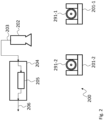
- FIG 2 shows a wire processing device 200.
- the wire processing device 200 proceeds from FIG 1 Wire processing device 100 described in more detail and develops it to the effect that a second receiving device 201-2 is provided. Consequently, the cable processing device 200 has a first recording device 201 - 1 , a second recording device 201 - 2 , an image recording device 202 and an evaluation device 204 .
- the evaluation device 204 also has a trained algorithm 205 .
- the first receiving device 201-1 receives a first cable end 291-1 of a cable.
- the second receiving device 201-2 receives a second cable end 291-2 of the cable.
- the cable can thus be clamped in the form of a loop in a cable tensioner of a processing plant and the two cable ends 291-1, 291-2 can be recorded and evaluated in the cable processing device 200 at the same time.
- the image recording device 202 records one or more images 203 of each of the two cable ends 291-1, 291-2.
- the evaluation device 204 can process the images 203 in succession, i.e. it applies the trained algorithm 205 separately to each of the images, and generates a corresponding control signal 206.
- the above statements relating to the trained algorithm 105 apply to the trained algorithm 205.
- the evaluation device 204 applies the trained algorithm 205 to each of the directly recorded images 203 .
- the evaluation device 204 can, for example, generate a positive control signal 206 if exactly one of the two cable ends 291-1, 291-2 has a marking or a predetermined feature. In other specific embodiments, the evaluation device 204 can generate a positive control signal 206 if both cable ends 291-1, 291-2 have a marking or a predetermined feature.
- FIG 3 shows a wire processing device 300.
- the wire processing device 300 is based on the wire processing device 200 and develops it further in that the image recording device has a first camera 302-1 and a second camera 302-2. Consequently, the cable processing device 300 has a first recording device 301 - 1 , a second recording device 301 - 2 , a first camera 302 - 1 , a second camera 302 - 2 and an evaluation device 304 .
- the evaluation device 304 also has a trained algorithm 305 . It goes without saying that the second receiving device 301-2 is only optional and the cable processing device 300 can also have only one receiving device 301-1.
- the first camera 302-1 captures images 303-1 of the cable ends 391-1, 391-2 from a top view.
- the second camera 302-2 is offset or pivoted about the longitudinal axis of the cable ends 391-1, 391-2 by a predetermined angle relative to the first camera 302-1 and takes pictures 303-2 of the cable ends 391-1, 391- 2 from a perspective view.
- the evaluation device 304 can process the images 303-1, 303-2 in succession, i.e. it applies the trained algorithm 305 separately to each of the images and generates a corresponding control signal 306.
- the above statements on the trained algorithm 105 apply to the trained algorithm 305 and 205.
- the evaluation device 304 processes the directly recorded images 303-1, 303-2, ie applies the trained algorithm 305 to each of the directly recorded images, ie to the raw data.
- the evaluation device 304 can generate a positive control signal 306, for example, if exactly one of the two cable ends 391-1, 391-2 has a marking or a predetermined feature having.
- the marking can be designed in such a way that it is only visible in one of the two images 303-1, 303-2 of one of the cable ends 391-1, 391-2.
- the evaluation device 304 can only generate the positive control signal 306, for example, if the marking was identified in only one of the images 303-1, 303-2.
- the evaluation device 304 can generate a positive control signal 306 if both cable ends 391-1, 391-2 have a marking or a predetermined feature.
- the marking can be designed in such a way that it is only visible in one of two images 303-1, 303-2 of a cable end 391-1, 391-2.
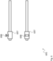
- figure 4 shows a cable end 491 as in one of the above in 1 , 2 , or 3 or subsequently in 8 can be processed in a side view (top) and a top view (bottom).
- the cable end 491 corresponds to that in figure 1 Cable end 191 shown.
- the cable end 491 consequently has a jacket 492 which encloses a braided shield 493 which is arranged on an insulator 494 .
- the insulator 494 encloses the conductor 495 of the cable.
- a rectangular marking 496 which represents the feature to be identified by the trained algorithm, is attached to the jacket 492 of the cable, by way of example only. It is understood that other forms of marker 496 are also possible.
- marking 496 can also be used as an identifying feature on other types of cables, not just on coaxial cables.
- marking 496 can also be used in connection with multi-wire data cables.
- figure 5 shows another cable end 591, as in one of the above in 1 , 2 , or 3 or subsequently in 8 exemplary cable processing devices 100, 200, 300, 800 described in more detail.
- the cable end 591 In contrast to the cable end 491, the cable end 591 has no marking.
- the feature to be identified is provided by a plug 597.
- the trained algorithm is thus trained to recognize whether or not the plug 597 is present at the cable end.
- the plug 597 is a round plug, which is why the cable end 591 is not shown in two different views. It goes without saying that any other type of plug can be provided instead of a round plug.
- a plug can be mounted on the cable end 591 .
- this plug does not have to represent the feature to be identified. Rather, a marking can be provided on the plug, which represents the feature to be identified. In such an embodiment, the marking on the connector is recognized by the trained algorithm.
- figure 6 shows yet another cable end 691, as in one of the above in 1 , 2 , or 3 or subsequently in 8 described as an example
- Cable processing devices 100, 200, 300, 800 can be processed.
- a plug 697 is provided at the cable end 691, which, however, does not represent the feature to be identified. Rather, the plug 697 has a locking device 698, in this case a secondary lock.
- the locking device 698 has a web from which pins 699 extend into the plug 697 . These pins 699 engage positively in the contacts of the plug 697 and thus prevent them from slipping out of the plug 697.
- figure 7 shows the cable end 691 in the locked state in which the pins 699 are fully recessed in the plug 697.
- the locking device 698 can be locked, for example, by pressing it into the plug 697 .
- the trained algorithm may be trained to recognize the presence or absence of the locking device 698 .
- the trained algorithm can be designed to recognize the state of the locking device 698, ie whether it is open or locked.
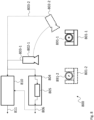
- FIG 8 shows a further embodiment of a cable processing device 800.
- the cable processing device 800 is based on the cable processing device 300.
- the cable processing device 800 consequently has a first recording device 801-1, a second recording device 801-2, a first camera 802-1, a second camera 802-2 and an evaluation device 804.
- the evaluation device 804 also has a trained algorithm 805 .
- the second camera 802-2 and the second recording device 801-2 are only optional and the cable processing device 800 can also have only one camera 802-1 and/or one recording device 301-1.
- the wire processing device 800 can consequently correspond to one of the wire processing devices 100, 200, 300 with regard to the elements listed here. Therefore, the above statements on the wire processing devices 100, 200, 300 apply analogously to the wire processing device 800.
- the wire processing device 800 also has an image processing device 810 .
- the image processing device 810 is arranged parallel to the evaluation device 804 and receives the images 803-1, 803-2 from the first camera 802-1 and, if present, from the second camera 802-2 parallel to the evaluation device 804.
- the image processing device 810 evaluates the received images 803-1, 803-2 independently of the evaluation device 804 and independently and generates an image processing signal 811, in particular exactly a single image processing signal 811, which represents a type of second control signal.
- the image processing signal 811 can be evaluated in a corresponding processing system for cables as a second signal in parallel with the control signal 806, which indicates whether the respective cable is fault-free or not. For example, such a cable processing system can only mark a cable as good if both the control signal 806 and the image processing signal 811 indicate a good cable.
- the linking of the two signals, ie the control signal 806 and the image processing signal 811, can also take place in the image processing device 810.
- the evaluation device 804 can provide the control signal 806 to the image processing device 810 (shown in dashed lines).
- the image processing device 810 can, for example, perform a logical AND operation of the Make the control signal 806 and the image processing signal 811 and output the ANDed signal to the cable processing system.
- the image processing device 810 can evaluate the images 803-1, 803-2 according to predetermined criteria and, for example, carry out pattern recognition, edge recognition or other functions of known image processing systems which, in particular, do not use artificial intelligence for the image evaluation.
- the image processing device 810 can consequently evaluate the received images 803-1, 803-2 for the presence of other features, in particular also a plurality of features, than the evaluation device 804.
- the image processing device 810 processes the directly recorded images 803-1, 803-2 or partial sections of the directly recorded images 803-1, 803-2.
- An intermediate program (the image processing software, in particular 'Eye Vision Technology' (EVT)) can also be connected between the cameras 802-1, 802-2 and the image processing device 810 for the provision of the partial section of the images 803-1, 803-2, whose only task is to crop the images 803-1, 803-2 that were immediately recorded and to forward only a defined section as a partial section or several defined partial sections one after the other to the image processing device 810.
- This task of cutting out a partial section from the directly recorded images 803 - 1 , 803 - 2 can also be carried out within the image processing device 810 .
- the directly recorded images 803-1, 803-2 can also be evaluated in the image processing device 810.
- a single intermediate program can be provided, which carries out the cropping of the directly recorded images 803-1, 803-2 both for the image processing device 810 and for the evaluation device 804. If the intermediate program is integrated in the image processing device 810, this can provide the respective image sections to the evaluation device 804.
- the trained algorithm 805 in the evaluation device 804 can be trained to replace the image processing device 810 and additionally to analyze the features in the images 803-1, 803-2, which the image processing device 810 analyzes as described above.
- Such a trained algorithm 805 only outputs a positive control signal 806 if all features in the images 803-1, 803-2 were positively checked.
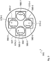
- figure 9 shows yet another cable end 991, as in one of the above in 1 , 2 , 3 or 8th cable processing devices 100, 200, 300, 800 described by way of example.
- the cable end 991 is shown in a front view of the longitudinal axis of the cable end 991 and has a plug 997 in which an insulator 994 with four openings 979-1, 979-2, 979-3, 979-4 is arranged.
- a connector 997 can, for example, be an HSD ("High Speed Data") connector. If the plug 997 is properly installed, there are two contact tongues 980-1, 980-2, 980-3, 980-4, 980-5 in each of the four openings 979-1, 979-2, 979-3, 979-4 980-6, 980-7.
- the number of two contact tongues 980-1, 980-2, 980-3, 980-4, 980-5, 980-6, 980-7 is chosen merely as an example and that more than two contact tongues 980-1 , 980-2, 980-3, 980-4, 980-5, 980-6, 980-7 can be present in each of the four openings 979-1, 979-2, 979-3, 979-4. It is also understood that fewer or more than four openings 979-1, 979-2, 979-3, 979-4 can be provided.
- the trained algorithm can be designed to check the cable end 991 to detect whether a corresponding number of contact tongues 980-1, 980-2, 980-3, 980-4, 980-5, 980-6, 980-7, so here e.g. two, are available.
- the trained algorithm can be trained to recognize in each case for the image of a single one of the four openings 979-1, 979-2, 979-3, 979-4, ie a corresponding section of an overall image of the cable end 991, whether in the respective opening 979-1, 979-2, 979-3, 979-4 the corresponding number of contact tongues 980-1, 980-2, 980-3, 980-4, 980-5, 980-6, 980-7 is present.
- the corresponding sections of the overall picture can be generated, for example, by an intermediate program, as has already been described above.
- results of the trained algorithm for all four openings 979-1, 979-2, 979-3, 979-4 can then be combined into an overall result and output as a control signal. All partial results can be linked using a logical AND link. A positive overall result is therefore only given if all partial results are positive.
- figure 10 shows a flowchart of a method for the automatic processing of cables 190.
- a first step S1 at least one cable end 191, 291-1, 291-2, 391-1, 391-2, 491, 591, 691, 891-1, 891-2, 991 of a cable 190 is fixed in a predetermined position .
- step S2 at least one image 103, 203, 303-1, 303-2, 803-1, 803-2 of the at least one cable end 191, 291-1, 291-2, 391-1, 391-2, 491, 591, 691, 891-1, 891-2, 991.
- a trained algorithm 105, 205, 305, 805 is applied to the at least one image 103, 203, 303-1, 303-2, 803-1, 803-2.
- step S3 the application of the trained algorithm 105, 205, 305, 805 in step S3 is provided directly, without further intermediate steps, with the image 103, 203, 303-1, 303-2 of the at least one cable end previously recorded in step S2 .
- step S4 a control signal 106, 206, 306, 806 is generated and output on the basis of at least one result output by the trained algorithm 105, 205, 305, 805.
- the trained algorithm 105, 205, 305, 805 mentioned can have, for example, a neural network, in particular a convolutional neural network.
- a trained algorithm 105, 205, 305, 805 can, for example, identify a predetermined feature 196, 496 in the at least one image 103, 203, 303-1, 303-2, 803-1, 803-2 and output a positive result , if the predetermined feature 196, 496 is identifiable in the image 103, 203, 303-1, 303-2, 803-1, 803-2.
- images 103, 203, 303-1, 303-2, 803-1, 803-2 can either be in a plan view of the respective cable end 191, 291-1, 291-2, 391-1, 391-2, 491, 591, 691, 891-1, 891-2, 991 or in a perspective view of the respective cable end 191, 291-1, 291-2, 391-1, 391-2, 491, 591, 691, 891-1, 891-2, 991.
- images 103, 203, 303-1, 303-2, 803-1, 803-2 both in a top view of the respective cable end 191, 291-1, 291-2, 391-1, 391-2 , 491, 591, 691, 891-1, 891-2, 991 as well as a perspective view of the respective cable end 191, 291-1, 291-2, 391-1, 391-2, 491, 591, 691, 891-1, 891-2, 991.
- the predetermined feature 196, 496 may include a marking on the cable end 191, 291-1, 291-2, 391-1, 391-2, 491, 591, 691, 891-1, 891-2, 991.
- the trained algorithm 105, 205, 305, 805 can be trained in such an embodiment, the marking at the cable end 191, 291-1, 291-2, 391-1, 391-2, 491, 591, 691, 891-1 , 891-2, 991.
- a positive control signal 106, 206, 306, 806 can be output in particular when the marker is at exactly one cable end 191, 291-1, 291-2, 391-1, 391-2, 491, 591, 691, 891-1 , 891-2, 991 is identified in at least one of the images 103, 203, 303-1, 303-2, 803-1, 803-2.
- An error signal can be issued if the marking is not at exactly one cable end 191, 291-1, 291-2, 391-1, 391-2, 491, 591, 691, 891-1, 891-2, 991 in at least one of images 103, 203, 303-1, 303-2, 803-1, 803-2 is identified.
- the predetermined feature 196, 496 can have a locking device 698, in particular a contact locking device 698.
- the trained algorithm 105, 205, 305, 805 may be trained, the presence of the locking device 698 at the cable end 191, 291-1, 291-2, 391-1, 391-2, 491, 591, 691, 891-1, 891-2, 991 to be identified.
- a positive control signal 106, 206, 306, 806 can be output in particular if the locking device 698 is identified in at least one of the images 103, 203, 303-1, 303-2, 803-1, 803-2.
- An error signal can be output if the specified marking is not identified in at least one of the images 103, 203, 303-1, 303-2, 803-1, 803-2.
- the predetermined feature 196, 496 can indicate the state of a locking device 698, in particular a contact locking device 698.
- the trained algorithm 105, 205, 305, 805 can be trained to determine the state of the locking device 698 at the cable end 191, 291-1, 291-2, 391-1, 391-2, 491, 591, 691, 891-1, 891-2, 991 to be identified.
- a positive control signal 106, 206, 306, 806 can be output if the state of the locking device 698 is identified as a locked state in at least one of the images 103, 203, 303-1, 303-2, 803-1, 803-2.
- An error signal can be issued if the state is not considered to be locked condition is identified.
- an error signal can be output if the state of the locking device 698 is identified as a locked state in at least one of the images 103, 203, 303-1, 303-2, 803-1, 803-2.
- a positive control signal 106, 206, 306, 806 can be issued if the condition is not identified as a locked condition.
Landscapes
- Engineering & Computer Science (AREA)
- Theoretical Computer Science (AREA)
- Physics & Mathematics (AREA)
- General Physics & Mathematics (AREA)
- Computer Vision & Pattern Recognition (AREA)
- Evolutionary Computation (AREA)
- Data Mining & Analysis (AREA)
- Artificial Intelligence (AREA)
- Quality & Reliability (AREA)
- General Engineering & Computer Science (AREA)
- General Health & Medical Sciences (AREA)
- Bioinformatics & Computational Biology (AREA)
- Bioinformatics & Cheminformatics (AREA)
- Health & Medical Sciences (AREA)
- Computing Systems (AREA)
- Databases & Information Systems (AREA)
- Evolutionary Biology (AREA)
- Medical Informatics (AREA)
- Software Systems (AREA)
- Multimedia (AREA)
- Life Sciences & Earth Sciences (AREA)
- Image Analysis (AREA)
- Image Processing (AREA)
Priority Applications (4)
| Application Number | Priority Date | Filing Date | Title |
|---|---|---|---|
| EP21197230.2A EP4152206A1 (fr) | 2021-09-16 | 2021-09-16 | Dispositif et procédé d'usinage de câbles |
| MX2022009775A MX2022009775A (es) | 2021-09-16 | 2022-08-09 | Dispositivo y metodo de procesamiento de cables. |
| US17/889,056 US20230081730A1 (en) | 2021-09-16 | 2022-08-16 | Cable processing device and method |
| CN202211050975.6A CN115830360A (zh) | 2021-09-16 | 2022-08-30 | 电缆处理设备和方法 |
Applications Claiming Priority (1)
| Application Number | Priority Date | Filing Date | Title |
|---|---|---|---|
| EP21197230.2A EP4152206A1 (fr) | 2021-09-16 | 2021-09-16 | Dispositif et procédé d'usinage de câbles |
Publications (1)
| Publication Number | Publication Date |
|---|---|
| EP4152206A1 true EP4152206A1 (fr) | 2023-03-22 |
Family
ID=77801627
Family Applications (1)
| Application Number | Title | Priority Date | Filing Date |
|---|---|---|---|
| EP21197230.2A Pending EP4152206A1 (fr) | 2021-09-16 | 2021-09-16 | Dispositif et procédé d'usinage de câbles |
Country Status (4)
| Country | Link |
|---|---|
| US (1) | US20230081730A1 (fr) |
| EP (1) | EP4152206A1 (fr) |
| CN (1) | CN115830360A (fr) |
| MX (1) | MX2022009775A (fr) |
Cited By (1)
| Publication number | Priority date | Publication date | Assignee | Title |
|---|---|---|---|---|
| EP4693219A1 (fr) * | 2024-08-08 | 2026-02-11 | MD ELEKTRONIK GmbH | Procédé de commande d'un traitement d'un tronçon de câble, unité de commande, dispositif de traitement de câble, procédé d'apprentissage d'un classificateur et dispositif d'entraînement |
Families Citing this family (2)
| Publication number | Priority date | Publication date | Assignee | Title |
|---|---|---|---|---|
| CN118507153B (zh) * | 2024-05-10 | 2025-04-18 | 湖南金缆电工科技有限责任公司 | 用于电缆加工的智能化控制系统及方法 |
| CN118570132A (zh) * | 2024-05-16 | 2024-08-30 | 南京莓跃霆网络科技有限公司 | 采用探入视觉检测的电力设备的电线管内部接头状态解析系统 |
Citations (1)
| Publication number | Priority date | Publication date | Assignee | Title |
|---|---|---|---|---|
| EP3855359A1 (fr) * | 2020-01-23 | 2021-07-28 | Schleuniger AG | Station d'usinage de câble, câbleuse pourvue de stations d'usinage de câble ainsi que procédé mis en uvre par ordinateur |
Family Cites Families (13)
| Publication number | Priority date | Publication date | Assignee | Title |
|---|---|---|---|---|
| US4649621A (en) * | 1986-02-21 | 1987-03-17 | Artos Engineering Company | Wire processing apparatus having control means |
| US7215811B2 (en) * | 2000-11-22 | 2007-05-08 | Osama Moselhi | Method and apparatus for the automated detection and classification of defects in sewer pipes |
| US9570892B2 (en) * | 2009-07-21 | 2017-02-14 | Cantega Technologies Inc. | Photogrammetric methods and apparatus for measurement of electrical equipment |
| US9548580B2 (en) * | 2014-05-23 | 2017-01-17 | Tyco Electronics Corporation | Terminal crimping system with wire alignment aid |
| US10713776B2 (en) * | 2017-04-13 | 2020-07-14 | Instrumental, Inc. | Method for predicting defects in assembly units |
| CN107133947A (zh) * | 2017-05-03 | 2017-09-05 | 广东电网有限责任公司珠海供电局 | 一种电缆瓷套终端红外图像特征提取和识别方法 |
| FI129412B (en) * | 2018-04-13 | 2022-01-31 | Maillefer Sa | An arrangement and a method for surface defect detection of a cable |
| US10810728B2 (en) * | 2018-11-19 | 2020-10-20 | The Boeing Company | Method for using a vision system to evaluate shield trims on shielded cables |
| MX2020008385A (es) * | 2019-08-18 | 2021-02-19 | Crimping & Stamping Tech Inc | Control a base de imagen de proceso de manufacturacion de conector y mazo de cables usando inteligencia artificial. |
| CN111798095B (zh) * | 2020-05-29 | 2023-01-20 | 广东电网有限责任公司广州供电局 | 一种基于神经网络电力电缆状态评价方法 |
| CN212410466U (zh) * | 2020-06-02 | 2021-01-26 | 浙江亘古电缆股份有限公司 | 一种电缆表面缺陷的检测装置 |
| CN112132811A (zh) * | 2020-09-24 | 2020-12-25 | 安徽德尔电气集团有限公司 | 一种电缆使用状态综合评估系统 |
| CN112557833B (zh) * | 2020-10-10 | 2022-04-12 | 国网河南省电力公司焦作供电公司 | 一种基于深度样本增强的电缆局部放电模式识别方法 |
-
2021
- 2021-09-16 EP EP21197230.2A patent/EP4152206A1/fr active Pending
-
2022
- 2022-08-09 MX MX2022009775A patent/MX2022009775A/es unknown
- 2022-08-16 US US17/889,056 patent/US20230081730A1/en active Pending
- 2022-08-30 CN CN202211050975.6A patent/CN115830360A/zh active Pending
Patent Citations (1)
| Publication number | Priority date | Publication date | Assignee | Title |
|---|---|---|---|---|
| EP3855359A1 (fr) * | 2020-01-23 | 2021-07-28 | Schleuniger AG | Station d'usinage de câble, câbleuse pourvue de stations d'usinage de câble ainsi que procédé mis en uvre par ordinateur |
Non-Patent Citations (2)
| Title |
|---|
| HANHIROVA JUSSI ET AL: "A machine learning based quality control system for power cable manufacturing", 2019 IEEE 17TH INTERNATIONAL CONFERENCE ON INDUSTRIAL INFORMATICS (INDIN), IEEE, vol. 1, 22 July 2019 (2019-07-22), pages 193 - 198, XP033700918, DOI: 10.1109/INDIN41052.2019.8972281 * |
| TAO XIAN ET AL: "Wire Defect Recognition of Spring-Wire Socket Using Multitask Convolutional Neural Networks", IEEE TRANSACTIONS ON COMPONENTS, PACKAGING AND MANUFACTURING TECHNOLOGY, IEEE, USA, vol. 8, no. 4, 1 April 2018 (2018-04-01), pages 689 - 698, XP011680770, ISSN: 2156-3950, [retrieved on 20180411], DOI: 10.1109/TCPMT.2018.2794540 * |
Cited By (1)
| Publication number | Priority date | Publication date | Assignee | Title |
|---|---|---|---|---|
| EP4693219A1 (fr) * | 2024-08-08 | 2026-02-11 | MD ELEKTRONIK GmbH | Procédé de commande d'un traitement d'un tronçon de câble, unité de commande, dispositif de traitement de câble, procédé d'apprentissage d'un classificateur et dispositif d'entraînement |
Also Published As
| Publication number | Publication date |
|---|---|
| CN115830360A (zh) | 2023-03-21 |
| MX2022009775A (es) | 2023-03-17 |
| US20230081730A1 (en) | 2023-03-16 |
Similar Documents
| Publication | Publication Date | Title |
|---|---|---|
| EP4152206A1 (fr) | Dispositif et procédé d'usinage de câbles | |
| EP4094188B1 (fr) | Station de traitement de câble, machine à câble dotée de stations de traitement de câble, et procédé mis en oeuvre par ordinateur | |
| WO2020160761A1 (fr) | Procédé et dispositif de contrôle | |
| DE102019208149A1 (de) | Nozzle Health mit neuronalem Netz | |
| DE3336470A1 (de) | Verfahren und anordnung zum vergleich von bildern | |
| DE102019127622B4 (de) | Abwehrgenerator, Verfahren zur Verhinderung eines Angriffs auf eine KI-Einheit und computerlesbares-Speichermedium | |
| EP4432137B1 (fr) | Procédé de fonctionnement d'un dispositif de traitement de câble, dispositif de traitement de câble, dispositif d'évaluation et/ou de commande pour un dispositif de traitement de câble et code de programme lisible par machine | |
| DE102021211610A1 (de) | Verfahren zum Trainieren eines neuronalen Lernmodells zum Detektieren von Produktionsfehlern | |
| EP3921810B1 (fr) | Procédé et dispositif d'identification automatisée d'un défaut d'un produit et/ou d'identification automatisée d'une cause du défaut du produit | |
| DE102024207482A1 (de) | Verfahren und vorrichtung zur automatischen optischen inspektion (aoi) | |
| DE102015225018A1 (de) | Verfahren zur Prüfung einer Mehrzahl von in gleicher Weise mit Bauteilen bestückten Bauteilträgern, Computerprogrammprodukt zur Durchführung eines solchen Verfahrens, und Prüfsystem zur Durchführung eines solchen Verfahrens | |
| DE69412844T2 (de) | Kodesequenzerkennung | |
| DE102022120150A1 (de) | Teileüberprüfungssystem mit generativem Trainingsmodell | |
| DE102022213930A1 (de) | Verfahren und System zum Verbessern der Robustheit eines Algorithmus des maschinellen Lernens | |
| EP4592944B1 (fr) | Dispositif de traitement d'image pour prendre en charge une évaluation qualitative et/ou quantitative de la qualité d'une liaison sertie, dispositif d'évaluation d'image et système de libération de fabrication pour dispositif de sertissage | |
| DE102022107831A1 (de) | Neuronale Netzwerkarchitektur für die automatisierte Teileprüfung | |
| DE102022204175A1 (de) | Verfahren und Vorrichtung für optische Inspektionen | |
| DE102021130505B4 (de) | Verfahren zur Bestimmung einer Beleuchtungsfarbe, Bildverarbeitungsvorrichtung und Aufnahmesystem | |
| DE102021201833A1 (de) | Vorrichtung zur Verarbeitung von mindestens einem Eingangsdatensatz unter Verwendung eines neuronalen Netzes sowie Verfahren | |
| DE102023134599B3 (de) | Vorrichtung und Verfahren zur bildbasierten Prüfung eines Kabelbaums | |
| DE102019120938B4 (de) | Druckinspektionsvorrichtung und Verfahren zur optischen Inspektion eines Druckbildes eines Druckobjekts | |
| EP4636662A1 (fr) | Procédé d'entraînement d'un modèle additif généralisé | |
| DE202021105594U1 (de) | System zur automatischen Auswahl und/oder Bewertung mindestens eines KI-Moduls und zur Klassifikation und/oder Regression von Eingangsdaten, ein computerlesbares Speichermedium und ein System zur Klassifikation und/oder Regression von Eingangsdaten | |
| DE102017217596A1 (de) | Verfahren zum Überprüfen eines elektronischen Bauelements, Verfahren zum Erzeugen eines Modells und Vorrichtung | |
| EP4254083A1 (fr) | Procédé de paramétrage d'un système de surveillance, dispositif de paramétrage et système de surveillance |
Legal Events
| Date | Code | Title | Description |
|---|---|---|---|
| PUAI | Public reference made under article 153(3) epc to a published international application that has entered the european phase |
Free format text: ORIGINAL CODE: 0009012 |
|
| STAA | Information on the status of an ep patent application or granted ep patent |
Free format text: STATUS: REQUEST FOR EXAMINATION WAS MADE |
|
| 17P | Request for examination filed |
Effective date: 20220603 |
|
| AK | Designated contracting states |
Kind code of ref document: A1 Designated state(s): AL AT BE BG CH CY CZ DE DK EE ES FI FR GB GR HR HU IE IS IT LI LT LU LV MC MK MT NL NO PL PT RO RS SE SI SK SM TR |
|
| STAA | Information on the status of an ep patent application or granted ep patent |
Free format text: STATUS: EXAMINATION IS IN PROGRESS |
|
| 17Q | First examination report despatched |
Effective date: 20231010 |
|
| RAP3 | Party data changed (applicant data changed or rights of an application transferred) |
Owner name: MD ELEKTRONIK GMBH |