EP4152258A1 - Procédé et appareil de suivi de partie cible, dispositif électronique et support de stockage lisible - Google Patents
Procédé et appareil de suivi de partie cible, dispositif électronique et support de stockage lisible Download PDFInfo
- Publication number
- EP4152258A1 EP4152258A1 EP20935079.2A EP20935079A EP4152258A1 EP 4152258 A1 EP4152258 A1 EP 4152258A1 EP 20935079 A EP20935079 A EP 20935079A EP 4152258 A1 EP4152258 A1 EP 4152258A1
- Authority
- EP
- European Patent Office
- Prior art keywords
- detection area
- target part
- current detection
- probability
- frame
- Prior art date
- Legal status (The legal status is an assumption and is not a legal conclusion. Google has not performed a legal analysis and makes no representation as to the accuracy of the status listed.)
- Withdrawn
Links
Images

Classifications
-
- G—PHYSICS
- G06—COMPUTING OR CALCULATING; COUNTING
- G06T—IMAGE DATA PROCESSING OR GENERATION, IN GENERAL
- G06T7/00—Image analysis
- G06T7/20—Analysis of motion
- G06T7/277—Analysis of motion involving stochastic approaches, e.g. using Kalman filters
-
- G—PHYSICS
- G06—COMPUTING OR CALCULATING; COUNTING
- G06T—IMAGE DATA PROCESSING OR GENERATION, IN GENERAL
- G06T7/00—Image analysis
- G06T7/20—Analysis of motion
- G06T7/246—Analysis of motion using feature-based methods, e.g. the tracking of corners or segments
- G06T7/248—Analysis of motion using feature-based methods, e.g. the tracking of corners or segments involving reference images or patches
-
- G—PHYSICS
- G06—COMPUTING OR CALCULATING; COUNTING
- G06T—IMAGE DATA PROCESSING OR GENERATION, IN GENERAL
- G06T7/00—Image analysis
- G06T7/10—Segmentation; Edge detection
- G06T7/11—Region-based segmentation
-
- G—PHYSICS
- G06—COMPUTING OR CALCULATING; COUNTING
- G06T—IMAGE DATA PROCESSING OR GENERATION, IN GENERAL
- G06T7/00—Image analysis
- G06T7/20—Analysis of motion
- G06T7/246—Analysis of motion using feature-based methods, e.g. the tracking of corners or segments
-
- G—PHYSICS
- G06—COMPUTING OR CALCULATING; COUNTING
- G06T—IMAGE DATA PROCESSING OR GENERATION, IN GENERAL
- G06T7/00—Image analysis
- G06T7/20—Analysis of motion
- G06T7/269—Analysis of motion using gradient-based methods
-
- G—PHYSICS
- G06—COMPUTING OR CALCULATING; COUNTING
- G06T—IMAGE DATA PROCESSING OR GENERATION, IN GENERAL
- G06T7/00—Image analysis
- G06T7/70—Determining position or orientation of objects or cameras
-
- G—PHYSICS
- G06—COMPUTING OR CALCULATING; COUNTING
- G06V—IMAGE OR VIDEO RECOGNITION OR UNDERSTANDING
- G06V10/00—Arrangements for image or video recognition or understanding
- G06V10/40—Extraction of image or video features
- G06V10/46—Descriptors for shape, contour or point-related descriptors, e.g. scale invariant feature transform [SIFT] or bags of words [BoW]; Salient regional features
- G06V10/462—Salient features, e.g. scale invariant feature transforms [SIFT]
-
- G—PHYSICS
- G06—COMPUTING OR CALCULATING; COUNTING
- G06V—IMAGE OR VIDEO RECOGNITION OR UNDERSTANDING
- G06V20/00—Scenes; Scene-specific elements
- G06V20/40—Scenes; Scene-specific elements in video content
- G06V20/46—Extracting features or characteristics from the video content, e.g. video fingerprints, representative shots or key frames
-
- G—PHYSICS
- G06—COMPUTING OR CALCULATING; COUNTING
- G06T—IMAGE DATA PROCESSING OR GENERATION, IN GENERAL
- G06T2207/00—Indexing scheme for image analysis or image enhancement
- G06T2207/10—Image acquisition modality
- G06T2207/10016—Video; Image sequence
-
- G—PHYSICS
- G06—COMPUTING OR CALCULATING; COUNTING
- G06T—IMAGE DATA PROCESSING OR GENERATION, IN GENERAL
- G06T2207/00—Indexing scheme for image analysis or image enhancement
- G06T2207/10—Image acquisition modality
- G06T2207/10024—Color image
-
- G—PHYSICS
- G06—COMPUTING OR CALCULATING; COUNTING
- G06T—IMAGE DATA PROCESSING OR GENERATION, IN GENERAL
- G06T2207/00—Indexing scheme for image analysis or image enhancement
- G06T2207/20—Special algorithmic details
- G06T2207/20076—Probabilistic image processing
-
- G—PHYSICS
- G06—COMPUTING OR CALCULATING; COUNTING
- G06T—IMAGE DATA PROCESSING OR GENERATION, IN GENERAL
- G06T2207/00—Indexing scheme for image analysis or image enhancement
- G06T2207/20—Special algorithmic details
- G06T2207/20081—Training; Learning
-
- G—PHYSICS
- G06—COMPUTING OR CALCULATING; COUNTING
- G06T—IMAGE DATA PROCESSING OR GENERATION, IN GENERAL
- G06T2207/00—Indexing scheme for image analysis or image enhancement
- G06T2207/20—Special algorithmic details
- G06T2207/20084—Artificial neural networks [ANN]
-
- G—PHYSICS
- G06—COMPUTING OR CALCULATING; COUNTING
- G06T—IMAGE DATA PROCESSING OR GENERATION, IN GENERAL
- G06T2207/00—Indexing scheme for image analysis or image enhancement
- G06T2207/30—Subject of image; Context of image processing
- G06T2207/30196—Human being; Person
-
- G—PHYSICS
- G06—COMPUTING OR CALCULATING; COUNTING
- G06T—IMAGE DATA PROCESSING OR GENERATION, IN GENERAL
- G06T2207/00—Indexing scheme for image analysis or image enhancement
- G06T2207/30—Subject of image; Context of image processing
- G06T2207/30196—Human being; Person
- G06T2207/30201—Face
-
- G—PHYSICS
- G06—COMPUTING OR CALCULATING; COUNTING
- G06T—IMAGE DATA PROCESSING OR GENERATION, IN GENERAL
- G06T2207/00—Indexing scheme for image analysis or image enhancement
- G06T2207/30—Subject of image; Context of image processing
- G06T2207/30232—Surveillance
-
- G—PHYSICS
- G06—COMPUTING OR CALCULATING; COUNTING
- G06T—IMAGE DATA PROCESSING OR GENERATION, IN GENERAL
- G06T2207/00—Indexing scheme for image analysis or image enhancement
- G06T2207/30—Subject of image; Context of image processing
- G06T2207/30241—Trajectory
Definitions
- Embodiments of the disclosure mainly relate to the field of artificial intelligence, particularly computer vision, and more particularly to a method and an apparatus for tracking a target part, an electronic device, and a computer-readable storage medium.
- the face recognition system realizes face recognition and comparison tasks through technologies such as, face detection, face tracking, face alignment, face in vivo, face recognition, which has a wide range of applications to fields such as, video surveillance, access control of buildings, face gates, financial verification.
- Face tracking technology refers to the technology of determining a facial movement trajectory and size changes of an object in a sequence of videos or frames. The technology is one of the important components in the face recognition system, as a method for accurately and quickly obtaining coordinates of the face location.
- the conventional face tracking technology may only obtain coordinates of a face box at the current frame. After the face is successfully tracked, the coordinates of the face box may be output to a subsequent face alignment model for determining key points. When the face is blocked by an obstacle or exceeds an image acquisition range, the conventional face tracking technology cannot accurately determine whether there is a problem of face tracking failure, resulting in failure of the face recognition function.
- a solution for tracking a target part is provided.
- a method for tracking a target part may include determining a current detection area for detecting a target part of an object in a current frame of a video, based on a previous detection area of the target part in a previous frame of the video. The method further includes determining a probability that the target part is located within the current detection area. Additionally, the method may include in response to the probability being greater than or equal to a predetermined threshold, determining a subsequent detection area of the target part in a subsequent frame of the video based on at least the current detection area and the previous detection area.
- an apparatus for tracking a target part includes: a current detection area determination module, a probability determination module, and a subsequent detection area determination module.
- the current detection area determination module is configured to determine a current detection area for detecting a target part of an object in a current frame of a video, based on a previous detection area of the target part in a previous frame of the video.
- the probability determination module is configured to determine that the target part is located within the current detection area.
- the subsequent detection area determination module is configured to determine, in response to the probability being greater than or equal to a predetermined threshold, a subsequent detection area of the target part in a subsequent frame of the video based on at least the current detection area and the previous detection area.
- an electronic device in a third aspect of the disclosure, includes: one or more processors and storage means for storing one or more programs. When the one or more programs are executed by the one or more processors, the one or more processors are caused to implement the method according to the first aspect of the disclosure.
- a computer-readable storage medium has stored a computer program.
- the computer program is executed by a processor, the method according to the first aspect of the disclosure is implemented.
- a system for tracking a target part includes: a video acquisition module, a computing module in communication connection with the video acquisition module and an output display module.
- the video acquisition module is configured to provide a video associated with a target part of an object.
- the computing module is configured to implement the method according to the first aspect of the disclosure.
- the output display module is configured to display processing results of the computing module.
- the term “comprising” and the like should be understood as open-ended inclusion, i.e., “including but not limited to”.
- the term “based on” should be understood as “based at least in part on”.
- the terms “an embodiment” or “the embodiment” should be understood to mean “at least one embodiment”.
- the terms “first”, “second”, etc. may refer to different or the same objects. Other explicit and implicit definitions may also be included below.
- the face tracking technology generally has the following three optimization solutions.
- a target part tracking solution is proposed.
- a motion prediction function for a target part may be increased on the basis of target part detection. After a detection area where the target part is located in a current frame is predicted based on a previous frame, it is determined whether the target part is located in the detection area while key points of the target part are determined based on the detection area. When it is judged that the target part is still located in the detection area, meaning that the motion prediction function is normal, it may be continued to predict a detection area of the target part in a subsequent frame. In this way, there is no need to use a complex model for target part detection with large computational power demands.
- the prediction result may be corrected by directly calling the model for target part detection at this time. In this way, even if the target part of the monitored object is occluded or the monitored object moves irregularly, the detection area in the subsequent frame may be determined with low cost and high accuracy.
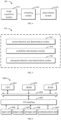
- FIG 1 illustrates a schematic diagram of an example environment 100 in which various embodiments of the disclosure may be implemented.
- an example environment 100 includes a frame 110 in a surveillance video, a computing device 120, and a determined detection area 130.
- the frame 110 may be one or more frames in a real-time surveillance video acquired by an image acquisition device, which is connected to the computing device 120.
- the image acquisition device may be set in a public place with a high human flow (e.g., video surveillance, face gate, etc.), so as to obtain image information of each person in the crowd passing through the public place.
- the image acquisition device may be located in a private place with a low human flow (e.g., building access control, financial verification, etc.).
- the objects for acquiring image information may not be limited to human, but may also include animals that need to be identified in batches (e.g., animals in zoos or breeding places) and still objects (e.g., goods on conveyor belts).
- the computing device 120 may receive the frame 110 to determine the detection area 130 of a target part (such as a face) of a monitored object.
- the detection area described herein is an area used for detecting the target part.
- the target part may be calibrated by a detection box or other suitable tools, or only a partial area on the image may be determined without actually calibrating.
- the detection area may have various implementation forms, for example, may have a shape such as a rectangle, a circle, an ellipse, an irregular shape, etc., or may be delineated by a solid line, a dotted line, a dot-dash line, and the like.
- the computing device 120 may determine a plurality of key points of the target part in the detection area 130 through an artificial intelligence network such as a convolutional neural network (CNN) loaded therein and determine whether the target part is still within the detection area 130. In this way, it is monitored whether the prediction function of the computing device 120 is normal. In addition, when it is determined that the target part is not located within the detection area 130, the computing device 120 also needs to determine the detection area of the target part in the subsequent frame through another artificial intelligence network such as CNN loaded therein.
- CNN convolutional neural network
- the construction and usage of the artificial intelligence network in the computing device 120 may be described below by taking CNN as an example with reference to FIG 2 .
- FIG 2 illustrates a schematic diagram of a detailed example environment 200 in which various embodiments of the disclosure may be implemented.
- the example environment 200 may include a computing device 220, input frames 210, and output results 230.
- the example environment 200 may generally include a model training system 260 and a model application system 270.
- the model training system 260 and/or model application system 270 may be implemented in the computing device 120 as shown in FIG 1 or the computing device 220 as shown in FIG 2 .
- the structure and functionality of the example environment 200 are described for exemplary purposes only and are not intended to limit the scope of the subject matter described herein.
- the subject matter described herein may be implemented in different structures and/or functions.
- the processes of determining the key points of the target part may be divided into two phases: a model training phase and a model application phase.
- the model training phase the model training system 260 may train CNN 240 that determines the key points and probability by using a training data set 250.
- the model application phase the model application system 270 may receive the trained CNN 240 such that the key points and probability are determined by the trained CNN 240 based on the input frames 210 as the output results 230.
- the training data set 250 may be a large number of annotated reference frames.
- the model training system 260 may train the CNN 240 that determines the detection area by using the training data set 250.
- the model application system 270 may receive the trained CNN 240 such that the detection area of the target part is determined by the trained CNN 240 based on the input frames 210.
- CNN 240 may be constructed as a learning network.
- a learning network may also be referred to as a learning model, or simply a network or model.
- the learning network may include multiple networks, e.g., which are respectively used to determine the key points of the target part (such as the face) of the monitored object, to determine a probability of whether the target part is located within the detection area, and to determine the detection area of the target part.
- Each of these networks may be a multi-layer neural network, which may be composed of a large number of neurons. Through the training process, corresponding parameters of the neurons in each network may be determined. The parameters of the neurons in these networks are collectively referred to as the parameters of the CNN 240.
- the training process of the CNN 240 may be performed in an iterative manner. Specifically, the model training system 260 may obtain reference images from the training data set 250 and use the reference images for one iteration of the training process to update the corresponding parameters of CNN 240. The model training system 260 may repeat the above process based on the plurality of reference images in the training data set 250, until at least some of the parameters of the CNN 240 are converged. In this way, final model parameters are obtained.
- FIG 3 illustrates a flowchart of a process 300 for tracking a target part according to an embodiment of the disclosure.
- the method 300 may be implemented in the computing device 120 in FIG 1 , the computing device 220 in FIG 2 , and the device shown in FIG 6 .
- the process 300 for tracking a target part in accordance with an embodiment of the disclosure is now described with reference to FIG 1 .
- the specific examples mentioned in the following description are all exemplary, and are not intended to limit the protection scope of the disclosure.
- the computing device 120 may determine a current detection area for detecting a target part of an object in a current frame of a video, based on a previous detection area of the target part in a previous frame of the video.
- the computing device 120 may apply the previous detection area to a location prediction model, to determine the current detection area.
- the location prediction model may be at least one of a Kalman filter, a Wiener filter, a strong tracking filter, a simple moving average prediction model, a double moving average prediction model, a single exponential smoothing model, a double exponential smoothing model, a Holt exponential smoothing model, etc.
- the Kalman filter located in the computing device 120 or connected to the computing device may predict a detection area in the next frame based on the frame and prior information in the Kalman filter.
- the calculation equations for algorithms in the Kalman filter are as follows.
- X k is a state vector of the kth frame and X k-1 is a state vector of the (k-1)th frame, Y k is an observation vector of the kth frame; A k, k-1 is a state transition matrix; H is an observation matrix, V k-1 is a system state noise of the (k-1)th frame, W k is an observation noise of the kth frame, Q and R are the corresponding variance matrices, respectively.
- X k, k-1 is a one-step state estimation value
- X k is a correction value of the prior estimation X k, k-1
- X k is a Kalman filter gain matrix
- P k, k-1 is a covariance matrix of X k, k-1
- P k is a covariance matrix of X k
- I is an identity matrix.
- the predicted detection area may be used to determine information for key points of the target part in the frame 110, e.g., the coordinates of each key point.
- the motion prediction based on the Kalman filter may be implemented flexibly.
- the detection area in the next frame may also be predicted based on the key point information of the target part in the previous frame and the prior information in the Kalman filter.
- the target part is the face, eyes, or fingerprint or the like of the object.
- the object is not limited to human.
- the objects described herein may be humans, as well as animals or objects in motion (e.g., goods on conveyor belts).
- the solutions of the disclosure may be applied to the recognition of multi-object scenes. Specifically, the disclosure may identify each or every animal in an area of a zoo or ranch that animals must pass through, and may also identify each or every commodity or factory product in a transport lane of goods in a mall or factory, so as to achieve automated logistics information management.
- the computing device 120 may determine the probability that the target part is within the current detection area.
- the computing device 120 may apply the current detection area to a probability determination model, such as one included in the above-described CNN 240, so as to determine the probability that the target part is located within the current detection area.
- the probability determination model may be trained based on a reference detection area in the reference frame and a pre-marked reference probability.
- the probability determination model quickly determines the probability that the target part is located within the current detection area by more simply determining the probability that a specific target part (such as a face) is present in the current detection area.
- the probability may be output as a score, ranging from 0 to 1. The higher the score, the higher the probability that there is a human face in the face box.
- the predetermined threshold for judging whether there is a human face may be 0.5 or other value.
- the artificial intelligence network in the computing device 120 may also determine a plurality of key points of the target part based on the current detection area while it is determined the probability that the target part is located within the current detection area.
- the computing device 120 may apply the current detection area to a key point determination model, such as one included in the above-described CNN 240, so as to determine the key points of the target part.
- the key point determination model is trained based on the reference detection area in the reference frame and pre-marked reference key points.
- the key point determination model and the above probability determination model may be combined into one model that simultaneously determines multiple key points of the target part and the probability that the target part is located within the current detection area based on the current detection area. In this way, it is possible to know whether the predicted detection area is correct without significantly increasing the computing power.
- the computing device 120 may determine whether the probability is greater than or equal to a predetermined threshold.
- the computing device 120 may determine a subsequent detection area for detecting the target part in a subsequent frame of the video based at least on the current detection area and the previous detection area.
- a location prediction model in the computing device 120 may determine the subsequent detection area based on the current detection area and prior information.
- the location prediction model may be at least one of a Kalman filter, a Wiener filter, a strong tracking filter, a simple moving average prediction model, a double moving average prediction model, a single exponential smoothing model, a double exponential smoothing model, a Holt exponential smoothing model, etc. In this way, when there is no abnormal movement or occlusion for the monitored object, the computing device 120 may determine the detection area of the target part by using the location prediction model with less computing power needs, thus significantly saving computing resources.
- the computing device 120 may detect the target part in the subsequent frame, and determine a subsequent detection area in the subsequent frame for detecting the target part based on the detection result.
- the computing device 120 may apply the subsequent frames to a area determination model (such as one included in the above-described CNN 240) that determines the subsequent detection areas of the target part.
- the area determination model is trained based on reference frames and pre-marked reference detection areas. In this way, the errors in motion prediction may be found in time and may be corrected by using a more accurate area determination model, thus ensuring the correctness of tracking an area.
- the area determination model may perform face area detection on the frame 110.
- basic facial features may be extracted from the frame 110 through a six-layer convolutional network.
- Each layer of convolutional network may perform one image down-sampling.
- a fixed number of face anchor areas with different sizes may be preset respectively, for performing face detection area regression.
- the face detection area is finally obtained.
- the above examples are only exemplary, convolutional network with other layer number may also be used, and they are not limited to determining the detection area of the human face. In this way, the detection area of the target part in the frame 110 may be quickly identified based on the area determination model.
- the disclosure may transfer most of the work for determining the detection area of the target part to a motion prediction model with less computing power needs, by adding the motion prediction model to a conventional system, thus saving computing power resources.
- the disclosure also integrates the above probability determination model on the basis of the key point determination model, so that the results of motion prediction may be checked frame by frame, and the area determination model may be used to obtain correct detection areas when prediction errors may occur.
- the disclosure improves the accuracy of detection area prediction while saving computing power.
- the key point determination model and the probability determination model are merged into one model, the time for the computing device 120 processing the input frame 110 is not increased.
- the disclosure improves the performance of the computing device 120 for determining the detection area in an almost flawless manner, thus optimizing the user experience.
- the disclosure also provides a system 400 for tracking a target part.
- the system includes an image acquisition module 410, which may be an image sensing device such as an RGB camera.
- the system 400 may also include a computing module 420 in communication with the image acquisition module 410, which is used to perform the various methods and processes described above, such as the process 300.
- the system 400 may include an output display module 430 for displaying processing results of the computing module 420 to a user.
- the output display module 430 can display face tracking results of the monitored object to the user.
- system-level face tracking may be achieved, and the computing power needs may be significantly reduced on the premise that the accuracy of face tracking and recognition remains unchanged.
- system 400 may be applied to face tracking scenarios for multiple pedestrians.
- the system 400 may be applied in a scenario of building access control or a scenario of financial verification.
- the system 400 may predict a face location of the monitored object in the next frame of a monitoring image, based on the first frame containing the face of the monitored object and the prior information, and determine whether the face of the object is still contained at the location while determining key points.
- the computing power for repeated face detection may be saved by predicting the location of the face, and the prediction accuracy may be determined by subsequent face review.
- the face detection may be restarted to ensure that the face tracking results are available at any time.
- the system 400 may also be applied in the field of video surveillance, especially in the case of performing body temperature monitoring on multiple monitored objects at the entrance of a subway or a venue. For example, when the faces of multiple monitored objects enter the monitoring field of view, the system 400 may predict each face location of each object in the next frame of each monitoring image based on the first frame of each monitoring image containing the faces of each object and the prior information, and determine whether the face of the corresponding object is still contained at the corresponding location while determining the key points. Since multiple faces may need to be tracked at the same time, the system 400 of the disclosure may greatly save computing power for repeated face detection, while ensuring that the face tracking results are correct and available at any time.
- FIG 5 illustrates a block diagram of an apparatus 500 for tracking a target part according to an embodiment of the disclosure.
- the apparatus 500 may include: a current detection area determination module 502, a probability determination module, and a subsequent detection area determination module.
- the current detection area determination module is configured to determine a current detection area for detecting a target part of an object in a current frame of a video, based on a previous detection area of the target part in a previous frame of the video.
- the probability determination module is configured to determine that the target part is located within the current detection area.
- the subsequent detection area determination module is configured to determine, in response to the probability being greater than or equal to a predetermined threshold, a subsequent detection area of the target part in a subsequent frame of the video based on at least the current detection area and the previous detection area.
- the apparatus 500 may further include: a target part detection module and an area determination module.
- the target part detection module is configured to in response to the probability being less than the predetermined threshold, detect the target part in the subsequent frame.
- the area determination module is configured to determine the subsequent detection area for detecting the target part in the subsequent frame based on a detected result.
- the target part detection module may include: a subsequent frame application module, configured to determine the subsequent detection area of the target part by applying the subsequent frame to an area determination model.
- the area determination model is obtained by training based on a reference frame and a pre-marked reference detection area.
- the probability determination module 504 may include: a current detection area application module, configured to determine the probability that the target part is located within the current detection area by applying the current detection area to a probability determination model.
- the probability determination model is obtained by training based on a reference detection area in a reference frame and a pre-marked reference probability.
- the current detection area determination module 502 may include: a previous detection area application module, configured to determine the current detection area by applying the previous detection area to a location prediction model.
- the location prediction model may be at least one of: a Kalman filter, aWiener filter, and a strong tracking filter.
- the target part may be at least one of face, eyes, and fingerprints of the object.
- the apparatus 500 may further include: a key point determination module, configured to determine key points of the target part based on the current detection area.
- the key point determination module may include: a current detection area application module, configured to determine the key points of the target part by applying the current detection area to a key point determination model.
- the key point determination model is obtained by training based on a reference detection area in a reference frame and pre-marked reference key points.
- FIG 6 illustrates a block diagram of a computing device 600 capable of implementing various embodiments of the disclosure.
- the device 600 may be used to implement the computing device 120 of FIG 1 or the computing device 220 of FIG 2 .
- the device 600 includes a central processing unit (CPU) 601 that may perform various appropriate actions and processes based on a computer program stored in a read only memory (ROM) 602 or loaded from a storage unit 608 into a random access memory (RAM) 603.
- ROM read only memory
- RAM random access memory
- various programs and data necessary for the operation of the device 600 may also be stored.
- the CPU 601, the ROM 602, and the RAM 603 are connected to each other through a bus 604.
- An input/output (I/O) interface 605 is also connected to the bus 604.
- Various components in the device 600 are connected to the I/O interface 605, including: an input unit 606, such as a keyboard, a mouse, etc.; an output unit 607, such as various types of displays, speakers, etc.; a storage unit 608, such as a magnetic disk, an optical disk, etc.; and a communication unit 609, such as a network card, a modem, a wireless communication transceiver, and the like.
- the communication unit 609 allows the device 600 to exchange information/data with other devices through a computer network such as the Internet and/or various telecommunication networks.
- the processing unit 601 performs the various methods and processes described above, such as the process 300.
- the process 300 may be implemented as computer software programs tangibly embodied on a machine-readable medium, such as the storage unit 608.
- part or all of the computer programs may be loaded and/or installed on the device 600 via the ROM 602 and/or the communication unit 609.
- the CPU 601 may be configured to perform the process 300 by any other suitable means (e.g., by means of firmware).
- exemplary types of hardware logic components include: a field programmable gate array (FPGA), an application specific integrated circuit (ASIC), an application specific standard product (ASSP), a system on a chip (SOC), a load programmable logic device (CPLD) and so on.
- FPGA field programmable gate array
- ASIC application specific integrated circuit
- ASSP application specific standard product
- SOC system on a chip
- CPLD load programmable logic device
- the program codes for implementing the method of the disclosure may be written in any combination of one or more programming languages. These program codes may be provided to a processor or controller of a general purpose computer, a special purpose computer or other programmable data processing apparatus, such that the program codes, when executed by the processor or controller, cause the functions/operations specified in the flowcharts and/or block diagrams to be implemented.
- the program codes may be executed completely on the machine, partially on the machine, partially on the machine as an independent software package and partially on a remote machine or completely on a remote machine or server.
- a machine-readable medium may be a tangible medium, which may contain or store a program for use by or in connection with an instruction execution system, an apparatus or a device.
- the machine-readable medium may be a machine-readable signal medium or a machine-readable storage medium.
- the machine-readable medium may include, but is not limited to, an electronic, magnetic, optical, electromagnetic, infrared, or semiconductor system, an apparatus, or a device, or any suitable combination of the above.
- machine-readable storage medium may include one or more wire-based electrical connections, a portable computer disk, a hard disk, a random access memory (RAM), a read only memory (ROM), an erasable programmable read-only memory (EPROM or flash memory), an optical fiber, a portable compact disk read-only memory (CD-ROM), an optical storage device, a magnetic storage device, or any suitable combination of the above.
- RAM random access memory
- ROM read only memory
- EPROM or flash memory erasable programmable read-only memory
- CD-ROM compact disk read-only memory
- magnetic storage device or any suitable combination of the above.
Landscapes
- Engineering & Computer Science (AREA)
- Physics & Mathematics (AREA)
- General Physics & Mathematics (AREA)
- Theoretical Computer Science (AREA)
- Computer Vision & Pattern Recognition (AREA)
- Multimedia (AREA)
- Image Analysis (AREA)
Applications Claiming Priority (2)
| Application Number | Priority Date | Filing Date | Title |
|---|---|---|---|
| CN202010415394.2A CN111627046A (zh) | 2020-05-15 | 2020-05-15 | 目标部位跟踪方法、装置、电子设备和可读存储介质 |
| PCT/CN2020/120965 WO2021227351A1 (fr) | 2020-05-15 | 2020-10-14 | Procédé et appareil de suivi de partie cible, dispositif électronique et support de stockage lisible |
Publications (2)
| Publication Number | Publication Date |
|---|---|
| EP4152258A1 true EP4152258A1 (fr) | 2023-03-22 |
| EP4152258A4 EP4152258A4 (fr) | 2024-03-20 |
Family
ID=72259799
Family Applications (1)
| Application Number | Title | Priority Date | Filing Date |
|---|---|---|---|
| EP20935079.2A Withdrawn EP4152258A4 (fr) | 2020-05-15 | 2020-10-14 | Procédé et appareil de suivi de partie cible, dispositif électronique et support de stockage lisible |
Country Status (6)
| Country | Link |
|---|---|
| US (1) | US20230196587A1 (fr) |
| EP (1) | EP4152258A4 (fr) |
| JP (1) | JP2023516480A (fr) |
| KR (1) | KR20230003346A (fr) |
| CN (1) | CN111627046A (fr) |
| WO (1) | WO2021227351A1 (fr) |
Families Citing this family (6)
| Publication number | Priority date | Publication date | Assignee | Title |
|---|---|---|---|---|
| CN111627046A (zh) * | 2020-05-15 | 2020-09-04 | 北京百度网讯科技有限公司 | 目标部位跟踪方法、装置、电子设备和可读存储介质 |
| CN112541418B (zh) * | 2020-12-04 | 2024-05-28 | 北京百度网讯科技有限公司 | 用于图像处理的方法、装置、设备、介质和程序产品 |
| CN112950672B (zh) * | 2021-03-03 | 2023-09-19 | 百度在线网络技术(北京)有限公司 | 确定关键点的位置的方法、装置和电子设备 |
| CN115147264A (zh) * | 2022-06-30 | 2022-10-04 | 北京百度网讯科技有限公司 | 图像处理方法、装置、电子设备及计算机可读存储介质 |
| KR20240165761A (ko) | 2023-05-16 | 2024-11-25 | 에스케이텔레콤 주식회사 | 칼만 필터를 기반으로 타겟의 위치를 추적하는 방법, 장치 및 컴퓨터 프로그램 |
| WO2025196908A1 (fr) * | 2024-03-18 | 2025-09-25 | 株式会社Nttドコモ | Dispositif, dispositif d'apprentissage et procédé |
Family Cites Families (23)
| Publication number | Priority date | Publication date | Assignee | Title |
|---|---|---|---|---|
| JP3788969B2 (ja) * | 2002-10-25 | 2006-06-21 | 三菱電機株式会社 | リアルタイム表情追跡装置 |
| US9852511B2 (en) * | 2013-01-22 | 2017-12-26 | Qualcomm Incoporated | Systems and methods for tracking and detecting a target object |
| US9295372B2 (en) * | 2013-09-18 | 2016-03-29 | Cerner Innovation, Inc. | Marking and tracking an area of interest during endoscopy |
| CN103985137B (zh) * | 2014-04-25 | 2017-04-05 | 深港产学研基地 | 应用于人机交互的运动物体跟踪方法及系统 |
| CN104008371B (zh) * | 2014-05-22 | 2017-02-15 | 南京邮电大学 | 一种基于多摄像机的区域可疑目标跟踪与识别方法 |
| CN105488811B (zh) * | 2015-11-23 | 2018-06-12 | 华中科技大学 | 一种基于深度梯度的目标跟踪方法与系统 |
| CN105741316B (zh) * | 2016-01-20 | 2018-10-16 | 西北工业大学 | 基于深度学习和多尺度相关滤波的鲁棒目标跟踪方法 |
| CN106570490B (zh) * | 2016-11-15 | 2019-07-16 | 华南理工大学 | 一种基于快速聚类的行人实时跟踪方法 |
| CN106846362B (zh) * | 2016-12-26 | 2020-07-24 | 歌尔科技有限公司 | 一种目标检测跟踪方法和装置 |
| CN107274433B (zh) * | 2017-06-21 | 2020-04-03 | 吉林大学 | 基于深度学习的目标跟踪方法、装置及存储介质 |
| US10452954B2 (en) * | 2017-09-14 | 2019-10-22 | Google Llc | Object detection and representation in images |
| CN109063581A (zh) * | 2017-10-20 | 2018-12-21 | 奥瞳系统科技有限公司 | 用于有限资源嵌入式视觉系统的增强型人脸检测和人脸跟踪方法和系统 |
| US10510157B2 (en) * | 2017-10-28 | 2019-12-17 | Altumview Systems Inc. | Method and apparatus for real-time face-tracking and face-pose-selection on embedded vision systems |
| JP7003628B2 (ja) * | 2017-12-19 | 2022-01-20 | 富士通株式会社 | 物体追跡プログラム、物体追跡装置、及び物体追跡方法 |
| CN108154159B (zh) * | 2017-12-25 | 2018-12-18 | 北京航空航天大学 | 一种基于多级检测器的具有自恢复能力的目标跟踪方法 |
| US10489918B1 (en) * | 2018-05-09 | 2019-11-26 | Figure Eight Technologies, Inc. | Video object tracking |
| CN108921879A (zh) * | 2018-05-16 | 2018-11-30 | 中国地质大学(武汉) | 基于区域选择的CNN和Kalman滤波的运动目标跟踪方法及系统 |
| CN108765455B (zh) * | 2018-05-24 | 2021-09-21 | 中国科学院光电技术研究所 | 一种基于tld算法的目标稳定跟踪方法 |
| CN110866428B (zh) * | 2018-08-28 | 2023-12-15 | 杭州海康威视数字技术股份有限公司 | 目标跟踪方法、装置、电子设备及存储介质 |
| CN109671103A (zh) * | 2018-12-12 | 2019-04-23 | 易视腾科技股份有限公司 | 目标跟踪方法及装置 |
| CN110490899A (zh) * | 2019-07-11 | 2019-11-22 | 东南大学 | 一种结合目标跟踪的可变形施工机械的实时检测方法 |
| CN110738687A (zh) * | 2019-10-18 | 2020-01-31 | 上海眼控科技股份有限公司 | 对象跟踪方法、装置、设备及存储介质 |
| CN111627046A (zh) * | 2020-05-15 | 2020-09-04 | 北京百度网讯科技有限公司 | 目标部位跟踪方法、装置、电子设备和可读存储介质 |
-
2020
- 2020-05-15 CN CN202010415394.2A patent/CN111627046A/zh active Pending
- 2020-10-14 WO PCT/CN2020/120965 patent/WO2021227351A1/fr not_active Ceased
- 2020-10-14 US US17/925,527 patent/US20230196587A1/en not_active Abandoned
- 2020-10-14 JP JP2022554423A patent/JP2023516480A/ja active Pending
- 2020-10-14 EP EP20935079.2A patent/EP4152258A4/fr not_active Withdrawn
- 2020-10-14 KR KR1020227043801A patent/KR20230003346A/ko not_active Withdrawn
Also Published As
| Publication number | Publication date |
|---|---|
| WO2021227351A1 (fr) | 2021-11-18 |
| US20230196587A1 (en) | 2023-06-22 |
| KR20230003346A (ko) | 2023-01-05 |
| JP2023516480A (ja) | 2023-04-19 |
| CN111627046A (zh) | 2020-09-04 |
| EP4152258A4 (fr) | 2024-03-20 |
Similar Documents
| Publication | Publication Date | Title |
|---|---|---|
| EP4152258A1 (fr) | Procédé et appareil de suivi de partie cible, dispositif électronique et support de stockage lisible | |
| CN110210302B (zh) | 多目标跟踪方法、装置、计算机设备及存储介质 | |
| KR102175491B1 (ko) | 상관 필터 기반 객체 추적 방법 | |
| CN108447078B (zh) | 基于视觉显著性的干扰感知跟踪算法 | |
| EP2131328A2 (fr) | Procédé de détection automatique et de suivi de plusieurs objets | |
| WO2021138893A1 (fr) | Procédé et appareil de reconnaissance de plaque d'immatriculation de véhicule, dispositif électronique et support d'enregistrement | |
| CN114743130A (zh) | 多目标行人跟踪方法及系统 | |
| US11688078B2 (en) | Video object detection | |
| CN113420682A (zh) | 车路协同中目标检测方法、装置和路侧设备 | |
| Ji et al. | RGB-D SLAM using vanishing point and door plate information in corridor environment | |
| CN117218171A (zh) | 深度估计模型优化与物体距离检测方法及相关设备 | |
| US20240037757A1 (en) | Method, device and storage medium for post-processing in multi-target tracking | |
| CN112529953A (zh) | 电梯的空间状态判断方法、装置及存储介质 | |
| CN111681266A (zh) | 船舶跟踪方法、系统、设备及存储介质 | |
| EP4636692A1 (fr) | Procédé, dispositif et support d'informations pour suivi de cible | |
| US20200081024A1 (en) | Method and device for detecting obstacle speed, computer device, and storage medium | |
| CN114627339B (zh) | 茂密丛林区域对越境人员的智能识别跟踪方法及存储介质 | |
| CN116309696A (zh) | 一种基于改进广义交并比的多类别多目标跟踪方法及装置 | |
| CN112053386B (zh) | 基于深度卷积特征自适应集成的目标跟踪方法 | |
| CN113963027A (zh) | 不确定性检测模型的训练、不确定性的检测方法及装置 | |
| CN117372928A (zh) | 一种视频目标检测方法、装置及相关设备 | |
| CN111860100B (zh) | 行人数量的确定方法、装置、电子设备及可读存储介质 | |
| Vu et al. | Safety-Assisted Driving Technology Based on Artificial Intelligence and Machine Learning for Moving Vehicles in Vietnam. | |
| CN114092516A (zh) | 一种多目标跟踪检测方法、装置、设备及介质 | |
| CN113715019B (zh) | 机器人控制方法、装置、机器人和存储介质 |
Legal Events
| Date | Code | Title | Description |
|---|---|---|---|
| STAA | Information on the status of an ep patent application or granted ep patent |
Free format text: STATUS: THE INTERNATIONAL PUBLICATION HAS BEEN MADE |
|
| PUAI | Public reference made under article 153(3) epc to a published international application that has entered the european phase |
Free format text: ORIGINAL CODE: 0009012 |
|
| STAA | Information on the status of an ep patent application or granted ep patent |
Free format text: STATUS: REQUEST FOR EXAMINATION WAS MADE |
|
| 17P | Request for examination filed |
Effective date: 20221215 |
|
| AK | Designated contracting states |
Kind code of ref document: A1 Designated state(s): AL AT BE BG CH CY CZ DE DK EE ES FI FR GB GR HR HU IE IS IT LI LT LU LV MC MK MT NL NO PL PT RO RS SE SI SK SM TR |
|
| DAV | Request for validation of the european patent (deleted) | ||
| DAX | Request for extension of the european patent (deleted) | ||
| STAA | Information on the status of an ep patent application or granted ep patent |
Free format text: STATUS: THE APPLICATION HAS BEEN WITHDRAWN |
|
| A4 | Supplementary search report drawn up and despatched |
Effective date: 20240216 |
|
| RIC1 | Information provided on ipc code assigned before grant |
Ipc: G06T 7/277 20170101ALI20240212BHEP Ipc: G06T 7/269 20170101ALI20240212BHEP Ipc: G06T 7/246 20170101AFI20240212BHEP |
|
| 18W | Application withdrawn |
Effective date: 20240312 |