EP4152472A1 - Batterieverwaltungssystem, batterieverwaltungsverfahren, batteriepack und elektrofahrzeug - Google Patents
Batterieverwaltungssystem, batterieverwaltungsverfahren, batteriepack und elektrofahrzeug Download PDFInfo
- Publication number
- EP4152472A1 EP4152472A1 EP21858592.5A EP21858592A EP4152472A1 EP 4152472 A1 EP4152472 A1 EP 4152472A1 EP 21858592 A EP21858592 A EP 21858592A EP 4152472 A1 EP4152472 A1 EP 4152472A1
- Authority
- EP
- European Patent Office
- Prior art keywords
- battery
- voltage
- current
- soc
- charging
- Prior art date
- Legal status (The legal status is an assumption and is not a legal conclusion. Google has not performed a legal analysis and makes no representation as to the accuracy of the status listed.)
- Pending
Links
Images


Classifications
-
- H—ELECTRICITY
- H01—ELECTRIC ELEMENTS
- H01M—PROCESSES OR MEANS, e.g. BATTERIES, FOR THE DIRECT CONVERSION OF CHEMICAL ENERGY INTO ELECTRICAL ENERGY
- H01M10/00—Secondary cells; Manufacture thereof
- H01M10/42—Methods or arrangements for servicing or maintenance of secondary cells or secondary half-cells
- H01M10/425—Structural combination with electronic components, e.g. electronic circuits integrated to the outside of the casing
-
- B—PERFORMING OPERATIONS; TRANSPORTING
- B60—VEHICLES IN GENERAL
- B60L—PROPULSION OF ELECTRICALLY-PROPELLED VEHICLES; SUPPLYING ELECTRIC POWER FOR AUXILIARY EQUIPMENT OF ELECTRICALLY-PROPELLED VEHICLES; ELECTRODYNAMIC BRAKE SYSTEMS FOR VEHICLES IN GENERAL; MAGNETIC SUSPENSION OR LEVITATION FOR VEHICLES; MONITORING OPERATING VARIABLES OF ELECTRICALLY-PROPELLED VEHICLES; ELECTRIC SAFETY DEVICES FOR ELECTRICALLY-PROPELLED VEHICLES
- B60L58/00—Methods or circuit arrangements for monitoring or controlling batteries or fuel cells, specially adapted for electric vehicles
- B60L58/10—Methods or circuit arrangements for monitoring or controlling batteries or fuel cells, specially adapted for electric vehicles for monitoring or controlling batteries
- B60L58/12—Methods or circuit arrangements for monitoring or controlling batteries or fuel cells, specially adapted for electric vehicles for monitoring or controlling batteries responding to state of charge [SoC]
-
- B—PERFORMING OPERATIONS; TRANSPORTING
- B60—VEHICLES IN GENERAL
- B60L—PROPULSION OF ELECTRICALLY-PROPELLED VEHICLES; SUPPLYING ELECTRIC POWER FOR AUXILIARY EQUIPMENT OF ELECTRICALLY-PROPELLED VEHICLES; ELECTRODYNAMIC BRAKE SYSTEMS FOR VEHICLES IN GENERAL; MAGNETIC SUSPENSION OR LEVITATION FOR VEHICLES; MONITORING OPERATING VARIABLES OF ELECTRICALLY-PROPELLED VEHICLES; ELECTRIC SAFETY DEVICES FOR ELECTRICALLY-PROPELLED VEHICLES
- B60L53/00—Methods of charging batteries, specially adapted for electric vehicles; Charging stations or on-board charging equipment therefor; Exchange of energy storage elements in electric vehicles
- B60L53/60—Monitoring or controlling charging stations
- B60L53/66—Data transfer between charging stations and vehicles
-
- G—PHYSICS
- G01—MEASURING; TESTING
- G01R—MEASURING ELECTRIC VARIABLES; MEASURING MAGNETIC VARIABLES
- G01R31/00—Arrangements for testing electric properties; Arrangements for locating electric faults; Arrangements for electrical testing characterised by what is being tested not provided for elsewhere
- G01R31/36—Arrangements for testing, measuring or monitoring the electrical condition of accumulators or electric batteries, e.g. capacity or state of charge [SoC]
- G01R31/385—Arrangements for measuring battery or accumulator variables
- G01R31/387—Determining ampere-hour charge capacity or SoC
-
- G—PHYSICS
- G01—MEASURING; TESTING
- G01R—MEASURING ELECTRIC VARIABLES; MEASURING MAGNETIC VARIABLES
- G01R31/00—Arrangements for testing electric properties; Arrangements for locating electric faults; Arrangements for electrical testing characterised by what is being tested not provided for elsewhere
- G01R31/36—Arrangements for testing, measuring or monitoring the electrical condition of accumulators or electric batteries, e.g. capacity or state of charge [SoC]
- G01R31/396—Acquisition or processing of data for testing or for monitoring individual cells or groups of cells within a battery
-
- H—ELECTRICITY
- H01—ELECTRIC ELEMENTS
- H01M—PROCESSES OR MEANS, e.g. BATTERIES, FOR THE DIRECT CONVERSION OF CHEMICAL ENERGY INTO ELECTRICAL ENERGY
- H01M10/00—Secondary cells; Manufacture thereof
- H01M10/05—Accumulators with non-aqueous electrolyte
- H01M10/052—Li-accumulators
-
- H—ELECTRICITY
- H01—ELECTRIC ELEMENTS
- H01M—PROCESSES OR MEANS, e.g. BATTERIES, FOR THE DIRECT CONVERSION OF CHEMICAL ENERGY INTO ELECTRICAL ENERGY
- H01M10/00—Secondary cells; Manufacture thereof
- H01M10/42—Methods or arrangements for servicing or maintenance of secondary cells or secondary half-cells
- H01M10/44—Methods for charging or discharging
-
- H—ELECTRICITY
- H01—ELECTRIC ELEMENTS
- H01M—PROCESSES OR MEANS, e.g. BATTERIES, FOR THE DIRECT CONVERSION OF CHEMICAL ENERGY INTO ELECTRICAL ENERGY
- H01M10/00—Secondary cells; Manufacture thereof
- H01M10/42—Methods or arrangements for servicing or maintenance of secondary cells or secondary half-cells
- H01M10/44—Methods for charging or discharging
- H01M10/441—Methods for charging or discharging for several batteries or cells simultaneously or sequentially
-
- H—ELECTRICITY
- H01—ELECTRIC ELEMENTS
- H01M—PROCESSES OR MEANS, e.g. BATTERIES, FOR THE DIRECT CONVERSION OF CHEMICAL ENERGY INTO ELECTRICAL ENERGY
- H01M10/00—Secondary cells; Manufacture thereof
- H01M10/42—Methods or arrangements for servicing or maintenance of secondary cells or secondary half-cells
- H01M10/44—Methods for charging or discharging
- H01M10/448—End of discharge regulating measures
-
- H—ELECTRICITY
- H01—ELECTRIC ELEMENTS
- H01M—PROCESSES OR MEANS, e.g. BATTERIES, FOR THE DIRECT CONVERSION OF CHEMICAL ENERGY INTO ELECTRICAL ENERGY
- H01M10/00—Secondary cells; Manufacture thereof
- H01M10/42—Methods or arrangements for servicing or maintenance of secondary cells or secondary half-cells
- H01M10/46—Accumulators structurally combined with charging apparatus
-
- H—ELECTRICITY
- H01—ELECTRIC ELEMENTS
- H01M—PROCESSES OR MEANS, e.g. BATTERIES, FOR THE DIRECT CONVERSION OF CHEMICAL ENERGY INTO ELECTRICAL ENERGY
- H01M10/00—Secondary cells; Manufacture thereof
- H01M10/42—Methods or arrangements for servicing or maintenance of secondary cells or secondary half-cells
- H01M10/48—Accumulators combined with arrangements for measuring, testing or indicating the condition of cells, e.g. the level or density of the electrolyte
-
- H—ELECTRICITY
- H02—GENERATION; CONVERSION OR DISTRIBUTION OF ELECTRIC POWER
- H02J—ELECTRIC POWER NETWORKS; CIRCUIT ARRANGEMENTS OR SYSTEMS FOR SUPPLYING OR DISTRIBUTING ELECTRIC POWER; SYSTEMS FOR STORING ELECTRIC ENERGY
- H02J7/00—Circuit arrangements for charging or discharging batteries or for supplying loads from batteries
- H02J7/80—Circuit arrangements for charging or discharging batteries or for supplying loads from batteries including monitoring or indicating arrangements
- H02J7/82—Control of state of charge [SOC]
-
- H—ELECTRICITY
- H02—GENERATION; CONVERSION OR DISTRIBUTION OF ELECTRIC POWER
- H02J—ELECTRIC POWER NETWORKS; CIRCUIT ARRANGEMENTS OR SYSTEMS FOR SUPPLYING OR DISTRIBUTING ELECTRIC POWER; SYSTEMS FOR STORING ELECTRIC ENERGY
- H02J7/00—Circuit arrangements for charging or discharging batteries or for supplying loads from batteries
- H02J7/90—Regulation of charging or discharging current or voltage
- H02J7/94—Regulation of charging or discharging current or voltage in response to battery current
-
- H—ELECTRICITY
- H02—GENERATION; CONVERSION OR DISTRIBUTION OF ELECTRIC POWER
- H02J—ELECTRIC POWER NETWORKS; CIRCUIT ARRANGEMENTS OR SYSTEMS FOR SUPPLYING OR DISTRIBUTING ELECTRIC POWER; SYSTEMS FOR STORING ELECTRIC ENERGY
- H02J7/00—Circuit arrangements for charging or discharging batteries or for supplying loads from batteries
- H02J7/90—Regulation of charging or discharging current or voltage
- H02J7/96—Regulation of charging or discharging current or voltage in response to battery voltage
-
- B—PERFORMING OPERATIONS; TRANSPORTING
- B60—VEHICLES IN GENERAL
- B60L—PROPULSION OF ELECTRICALLY-PROPELLED VEHICLES; SUPPLYING ELECTRIC POWER FOR AUXILIARY EQUIPMENT OF ELECTRICALLY-PROPELLED VEHICLES; ELECTRODYNAMIC BRAKE SYSTEMS FOR VEHICLES IN GENERAL; MAGNETIC SUSPENSION OR LEVITATION FOR VEHICLES; MONITORING OPERATING VARIABLES OF ELECTRICALLY-PROPELLED VEHICLES; ELECTRIC SAFETY DEVICES FOR ELECTRICALLY-PROPELLED VEHICLES
- B60L2240/00—Control parameters of input or output; Target parameters
- B60L2240/40—Drive Train control parameters
- B60L2240/54—Drive Train control parameters related to batteries
- B60L2240/545—Temperature
-
- B—PERFORMING OPERATIONS; TRANSPORTING
- B60—VEHICLES IN GENERAL
- B60L—PROPULSION OF ELECTRICALLY-PROPELLED VEHICLES; SUPPLYING ELECTRIC POWER FOR AUXILIARY EQUIPMENT OF ELECTRICALLY-PROPELLED VEHICLES; ELECTRODYNAMIC BRAKE SYSTEMS FOR VEHICLES IN GENERAL; MAGNETIC SUSPENSION OR LEVITATION FOR VEHICLES; MONITORING OPERATING VARIABLES OF ELECTRICALLY-PROPELLED VEHICLES; ELECTRIC SAFETY DEVICES FOR ELECTRICALLY-PROPELLED VEHICLES
- B60L2240/00—Control parameters of input or output; Target parameters
- B60L2240/40—Drive Train control parameters
- B60L2240/54—Drive Train control parameters related to batteries
- B60L2240/547—Voltage
-
- B—PERFORMING OPERATIONS; TRANSPORTING
- B60—VEHICLES IN GENERAL
- B60L—PROPULSION OF ELECTRICALLY-PROPELLED VEHICLES; SUPPLYING ELECTRIC POWER FOR AUXILIARY EQUIPMENT OF ELECTRICALLY-PROPELLED VEHICLES; ELECTRODYNAMIC BRAKE SYSTEMS FOR VEHICLES IN GENERAL; MAGNETIC SUSPENSION OR LEVITATION FOR VEHICLES; MONITORING OPERATING VARIABLES OF ELECTRICALLY-PROPELLED VEHICLES; ELECTRIC SAFETY DEVICES FOR ELECTRICALLY-PROPELLED VEHICLES
- B60L2240/00—Control parameters of input or output; Target parameters
- B60L2240/40—Drive Train control parameters
- B60L2240/54—Drive Train control parameters related to batteries
- B60L2240/549—Current
-
- H—ELECTRICITY
- H01—ELECTRIC ELEMENTS
- H01M—PROCESSES OR MEANS, e.g. BATTERIES, FOR THE DIRECT CONVERSION OF CHEMICAL ENERGY INTO ELECTRICAL ENERGY
- H01M10/00—Secondary cells; Manufacture thereof
- H01M10/42—Methods or arrangements for servicing or maintenance of secondary cells or secondary half-cells
- H01M10/425—Structural combination with electronic components, e.g. electronic circuits integrated to the outside of the casing
- H01M2010/4271—Battery management systems including electronic circuits, e.g. control of current or voltage to keep battery in healthy state, cell balancing
-
- H—ELECTRICITY
- H01—ELECTRIC ELEMENTS
- H01M—PROCESSES OR MEANS, e.g. BATTERIES, FOR THE DIRECT CONVERSION OF CHEMICAL ENERGY INTO ELECTRICAL ENERGY
- H01M2220/00—Batteries for particular applications
- H01M2220/20—Batteries in motive systems, e.g. vehicle, ship, plane
-
- Y—GENERAL TAGGING OF NEW TECHNOLOGICAL DEVELOPMENTS; GENERAL TAGGING OF CROSS-SECTIONAL TECHNOLOGIES SPANNING OVER SEVERAL SECTIONS OF THE IPC; TECHNICAL SUBJECTS COVERED BY FORMER USPC CROSS-REFERENCE ART COLLECTIONS [XRACs] AND DIGESTS
- Y02—TECHNOLOGIES OR APPLICATIONS FOR MITIGATION OR ADAPTATION AGAINST CLIMATE CHANGE
- Y02E—REDUCTION OF GREENHOUSE GAS [GHG] EMISSIONS, RELATED TO ENERGY GENERATION, TRANSMISSION OR DISTRIBUTION
- Y02E60/00—Enabling technologies; Technologies with a potential or indirect contribution to GHG emissions mitigation
- Y02E60/10—Energy storage using batteries
-
- Y—GENERAL TAGGING OF NEW TECHNOLOGICAL DEVELOPMENTS; GENERAL TAGGING OF CROSS-SECTIONAL TECHNOLOGIES SPANNING OVER SEVERAL SECTIONS OF THE IPC; TECHNICAL SUBJECTS COVERED BY FORMER USPC CROSS-REFERENCE ART COLLECTIONS [XRACs] AND DIGESTS
- Y02—TECHNOLOGIES OR APPLICATIONS FOR MITIGATION OR ADAPTATION AGAINST CLIMATE CHANGE
- Y02T—CLIMATE CHANGE MITIGATION TECHNOLOGIES RELATED TO TRANSPORTATION
- Y02T10/00—Road transport of goods or passengers
- Y02T10/60—Other road transportation technologies with climate change mitigation effect
- Y02T10/70—Energy storage systems for electromobility, e.g. batteries
Definitions
- the present disclosure relates to battery charge control.
- a multi-stage constant-current charging' namely, stepwise adjustment of the current rate of the charge current according to the State Of Charge (SOC) or voltage of the battery during charging.
- the current rate is a value obtained by dividing the charge current by the maximum capacity of the battery, and may be referred to as 'C-rate', and it's unit is 'C'.
- a multi-stage constant-current charge map includes at least one data array recording a correlation between a plurality of voltage ranges and a plurality of C-rates.
- a charging procedure using the multi-stage constant-current charge map includes repeating the process of supplying the charge current of the next C-rate to the battery each time the voltage of the battery reaches the upper limit value of each voltage range.
- the charging procedure using the multi-stage constant-current charge map according to the related art does not consider the operational state (for example, degradation) of the battery that changes over time.
- the present disclosure is designed to solve the above-described problem, and therefore the present disclosure is directed to providing a battery management system, a battery management method, a battery pack and an electric vehicle, in which a multi-stage constant-current charge map is updated according to the operational state of a battery based on the voltage and current of the battery monitored during charging using the multi-stage constant-current charge map.
- the present disclosure is further directed to providing a battery management system, a battery management method, a battery pack and an electric vehicle, in which even though the charging procedure is not completed across all of a plurality of voltage ranges, the C-rate associated with the remaining voltage range having not undergone constant-current charging is updated based on the update result of the C-rate associated with at least one voltage range having undergone constant-current charging.
- a battery management system includes a sensing unit configured to generate a sensing signal indicating a battery voltage and a battery current of a battery, a memory unit to store a charge map recording a correlation between first to n th reference currents, first to n th reference voltage ranges, first to n th reference states of charge (SOCs) and first to n th reference voltage curves for multi-stage constant-current charging of the battery, and a control unit configured to determine a SOC of the battery based on the sensing signal.
- a sensing unit configured to generate a sensing signal indicating a battery voltage and a battery current of a battery
- a memory unit to store a charge map recording a correlation between first to n th reference currents, first to n th reference voltage ranges, first to n th reference states of charge (SOCs) and first to n th reference voltage curves for multi-stage constant-current charging of the battery
- SOCs states of charge
- the control unit is configured to command constant-current charging using a k th reference current corresponding to a k th reference voltage range to which the battery voltage belongs to a charging circuit connected to the battery, in response to a charge start command.
- the control unit is configured to update the charge map by comparing a k th measured voltage curve indicating a correlation between the battery voltage and the SOC of the battery over a charging period of the constant-current charging with a k th reference voltage curve of the charge map, in response to the battery voltage having reached an upper limit of the k th reference voltage range.
- n is a natural number or 2 or greater
- k is a natural number of n or smaller.
- the control unit may be configured to update the k th reference current based on a ratio of an average SOC of the k th measured voltage curve to an average SOC of the k th reference voltage curve.
- the control unit may be configured to update the k th reference current based on a ratio of an average voltage of the k th reference voltage curve to an average voltage of the k th measured voltage curve.
- the control unit may be configured to update the k th reference current based on a first ratio of an average SOC of the k th measured voltage curve to an average SOC of the k th reference voltage curve and a second ratio of an average voltage of the k th reference voltage curve to an average voltage of the k th measured voltage curve.
- the control unit may be configured to update the k th reference current based on a ratio of a SOC of interest to the k th reference SOC.
- the SOC of interest is a SOC of the battery at a point in time when the battery voltage reaches the upper limit of the k th reference voltage range.
- the control unit may be configured to update each remaining reference current except the k th reference current based on a ratio of the updated k th reference current to the k th reference current.
- the control unit may be configured to command constant-voltage charging using the upper limit of the k th reference voltage range to the charging circuit in response to the battery voltage having reached the upper limit of the k th reference voltage range.
- a battery pack according to another aspect of the present disclosure includes the battery management system.
- An electric vehicle includes the battery pack.
- a battery management method includes commanding constant-current charging using a k th reference current corresponding to a k th reference voltage range to which a battery voltage of a battery belongs to a charging circuit connected to the battery, using a charge map recording a correlation between first to n th reference currents, first to n th reference voltage ranges, first to n th reference SOCs and first to n th reference voltage curves for multi-stage constant-current charging of the battery, in response to a charge start command, and updating the charge map by comparing a k th measured voltage curve indicating a correlation between the battery voltage and a SOC of the battery over a charging period of the constant-current charging with a k th reference voltage curve of the charge map, in response to the battery voltage having reached an upper limit of the k th reference voltage range.
- n is a natural number of 2 or greater
- k is a natural number of n or smaller.
- Updating the charge map may include updating the k th reference current based on a ratio of an average SOC of the k th measured voltage curve to an average SOC of the k th reference voltage curve.
- the C-rate associated with the remaining voltage range having not undergone constant-current charging may be updated based on the update result of the C-rate associated with at least one voltage range having undergone constant-current charging.
- control unit refers to a processing unit of at least one function or operation, and this may be implemented by hardware and software either alone or in combination.
- FIG. 1 is a diagram exemplarily showing a configuration of an electric vehicle 1 according to the present disclosure.
- the electric vehicle 1 includes a battery pack 10, an inverter 30, an electric motor 40 and a charging circuit 50.
- the battery pack 10 includes a battery B, a switch 20 and a battery management system 100.
- the battery B includes at least one battery cell. Each battery cell is not limited to a particular type, and may include any battery cell that can be repeatedly recharged such as, for example, a lithium ion cell.
- the battery B may be coupled to the inverter 30 and/or the charging circuit 50 through a pair of power terminals provided in the battery pack 10.
- the switch 20 is connected in series to the battery B.
- the switch 20 is installed on a current path for the charge/discharge of the battery B.
- the on/off of the switch 20 is controlled in response to a switching signal from the battery management system 100.
- the switch 20 may be a mechanical relay that is turned on/off by the electromagnetic force of a coil or a semiconductor switch such as a Metal Oxide Semiconductor Field Effect transistor (MOSFET).
- MOSFET Metal Oxide Semiconductor Field Effect transistor
- the inverter 30 is provided to convert the direct current (DC) from the battery B to alternating current (AC) in response to a command from the battery management system 100.
- the electric motor 40 may be, for example, a three-phase AC motor. The electric motor 40 works using the AC power from the inverter 30.
- the battery management system 100 may be responsible for the general control related to the charge/discharge of the battery B.
- the battery management system 100 includes a sensing unit 110, a memory unit 120 and a control unit 140.
- the battery management system 100 may further include at least one of an interface unit 130 or a switch driver 150.
- the sensing unit 110 includes a voltage sensor 111 and a current sensor 112.
- the sensing unit 110 may further include a temperature sensor 113.
- the voltage sensor 111 is connected in parallel to the battery B and configured to detect a battery voltage across the battery B and generate a voltage signal indicating the detected battery voltage.
- the current sensor 112 is connected in series to the battery B through the current path.
- the current sensor 112 is configured to detect a battery current flowing through the battery B and generate a current signal indicating the detected battery current.
- the temperature sensor 113 is configured to detect a temperature of the battery B and generate a temperature signal indicating the detected temperature.
- the memory unit 120 may include at least one type of storage medium of flash memory type, hard disk type, Solid State Disk (SSD) type, Silicon Disk Drive (SDD) type, multimedia card micro type, random access memory (RAM), static random access memory (SRAM), read-only memory (ROM), electrically erasable programmable read-only memory (EEPROM) or programmable read-only memory (PROM).
- the memory unit 120 may store data and programs required for the computation operation by the control unit 140.
- the memory unit 120 may store data indicating the result of the computation operation by the control unit 140.
- the memory unit 120 stores a charge map.
- the charge map may be pre-stored in the memory unit 120 before the battery management system 100 is loaded, or may be received from, for example, a battery manufacturer, or a high-level controller 2 through the interface unit 130.
- the data recorded in the charge map may be preset based on test and/or simulation results of a sample battery having the same specification as the battery B.
- the charge map is used in a charging procedure for multi-stage constant-current charging of the battery B.
- the charge map records a correlation between (i) first to n th reference currents, (ii) first to n th reference voltage ranges, (iii) first to n th reference state of charges (SOCs) and (iv) first to n th reference voltage curves for multi-stage constant-current charging.
- n is a natural number of 2 or greater.
- the later reference current may be smaller than the earlier reference current.
- Each reference voltage range may be referred to as 'stage'.
- the interface unit 130 may include a communication circuit configured to support wired or wireless communication between the control unit 140 and the high-level controller 2 (for example, an Electronic Control Unit (ECU)).
- the wired communication may be, for example, controller area network (CAN) communication
- the wireless communication may be, for example, Zigbee or Bluetooth communication.
- the communication protocol is not limited to a particular type, and may include any communication protocol that supports the wired/wireless communication between the control unit 140 and the high-level controller 2.
- the interface unit 130 may include an output device (for example, a display, a speaker) to provide the information received from the control unit 140 and/or the high-level controller 2 in a recognizable format.
- the high-level controller 2 may control the inverter 30 based on battery information (for example, voltage, current, temperature, SOC) collected through the communication with the battery management system 100.
- the high-level controller 2 may transmit a charge start command or charge stop command to the battery management system 100 in response to the vehicle's user input.
- the control unit 140 may be operably coupled to the high-level controller 2, the switch 20, the charging circuit 50, the sensing unit 110, the memory unit 120, the interface unit 130 and/or the switch driver 150. Operably coupled refers to directly/indirectly connected to transmit and receive a signal in one or two directions.
- the switch driver 150 is electrically coupled to the control unit 140 and the switch SW.
- the switch driver 150 is configured to selectively turn on/off the switch SW in response to a command from the control unit 140.
- the control unit 140 may command the switch driver 150 to turn on the switch SW during the charging procedure.
- the control unit 140 may collect a sensing signal from the sensing unit 110.
- the sensing signal indicates the detected voltage signal, the detected current signal and/or the detected temperature signal in synchronization.
- the control unit 140 may be referred to as a 'battery controller', and may be implemented in hardware using at least one of application specific integrated circuits (ASICs), digital signal processors (DSPs), digital signal processing devices (DSPDs), programmable logic devices (PLDs), field programmable gate arrays (FPGAs), microprocessors or electrical units for performing the other functions.
- ASICs application specific integrated circuits
- DSPs digital signal processors
- DSPDs digital signal processing devices
- PLDs programmable logic devices
- FPGAs field programmable gate arrays
- the interface unit 130 may relay the bi-directional communication between the control unit 140 and the charging circuit 50 and the bi-directional communication between the control unit 140 and the high-level controller 2.
- the charging circuit 50 is configured to supply a charge current of a C-rate requested from the battery management system 100 to the battery B.
- the charging circuit 50 may be configured to supply a charge voltage having a voltage level requested from the battery management system 100 to the battery B.
- the control unit 140 is configured to start the charging procedure using the charge map in response to receiving the charge start command through the interface unit 130.
- the control unit 140 may terminate the charging procedure using the charge map in response to receiving the charge stop command through the interface unit 130.
- the control unit 140 may determine a SOC indicating the remaining capacity of the battery B based on the sensing signal. In determining the SOC, a well-known algorithm such as ampere counting, an open circuit voltage (OCV)-SOC curve and a Kalman filter may be used.
- the SOC of the battery B may be referred to as a 'battery SOC'.
- FIG. 2 is a diagram exemplarily showing the correlation between the reference current and the reference voltage range recorded in the charge map
- FIG. 3 is a diagram exemplarily showing the correlation between the reference voltage range and the reference SOC recorded in the charge map.
- a current profile 210 shown in FIG. 2 indicates the correlation between the first to fourth reference currents I 1 ⁇ I 4 and the first to fourth reference voltage ranges ⁇ V 1 ⁇ V 4 for the battery B at Beginning Of Life (BOL).
- the current profile 210 may be recorded in the charge map in the format of a data table.
- k may be referred to as a 'charge index'
- V k-1 and V k is the lower limit and upper limit of the k th reference voltage range V k , respectively.
- the first to fourth reference voltage ranges ⁇ V 1 ⁇ V 4 are consecutive in a sequential order. Accordingly, when i is a natural number of (n-1) or smaller, V i is the upper limit of the i th reference voltage range ⁇ V i , and the lower limit of the (i+1) th reference voltage range ⁇ V i+1 . For example, each of the upper limit of ⁇ V 2 and the lower limit of ⁇ V 3 is V 2 and equal to each other.
- V k may be referred to as a 'k th reference voltage'.
- the control unit 140 may command constant-current charging using the i th reference current I i to the charging circuit 50.
- the control unit 140 may command constant-current charging using the (i+1) th reference current I i+1 to the charging circuit 50. That is, the control unit 140 may change from the constant-current charging using the i th reference current I i to the constant-current charging using the (i+1) th reference current I i+1 .
- the control unit 140 may terminate the multi-stage constant-current charging using the charge map and command constant-voltage charging using the upper limit V n to the charging circuit 50. That is, the control unit 140 may change from the constant-current charging using the n th reference current I n to the constant-voltage charging using the upper limit V n .
- a first voltage profile 310 shown in FIG. 3 shows the correlation between the first to fourth reference SOCs S 1 ⁇ S 4 and the first to fourth reference voltages ⁇ V 1 ⁇ V 4 for the battery B at BOL.
- the first voltage profile 310 may be recorded in the charge map in the format of a data table.
- the first voltage profile 310 includes first to fourth reference voltage curves.
- the k th reference voltage curve is part corresponding to the k th reference voltage range ⁇ V k in the first voltage profile 310.
- S k indicates the SOC of the battery B when the battery voltage of the battery B at BOL reaches the k th reference voltage V k by the constant-current charging using the k th reference current I k .
- the battery voltage having reached the k th reference voltage V k before the SOC reaches the k th reference SOC S k during the constant-current charging using the k th reference current I k of the charge map indicates that the battery B degraded compared to when the battery B is at BOL
- Z k is the battery SOC when the battery voltage of the degraded battery B reaches the k th reference voltage V k , and is found lower than the k th reference SOC S k . That is, S 1 > Z 1 , S 2 > Z 2 , S 3 > Z 3 , S 4 > Z 4 .
- the battery voltage having reached the k th reference voltage V k before the SOC of the battery B reaches the k th reference SOC S k indicates that it is necessary to reduce the k th reference current I k in the next multi-stage constant-current charging procedure.
- the decrease in the k th reference current I k may be determined considering the voltage history and/or SOC history monitered during charging by the k th reference current I k .
- a third voltage profile 330 shown in FIG. 3 indicates the correlation between the change history of battery voltage and the change history of SOC monitored through the process of charging the degraded battery B by applying a battery management method (see FIG. 4 ) according to the present disclosure, respectively.
- the third voltage profile 330 includes first to fourth measured voltage curves.
- the k th measured voltage curve is part corresponding to the k th reference voltage range ⁇ V k in the third voltage profile 330.
- the control unit 140 monitors the battery voltage, the battery current and the SOC at a preset time interval (for example, 0.001 sec) during the constant-current charging using the k th reference current I k .
- the control unit 140 may change from the constant-current charging using the k th reference current I k to constant-voltage charging using the k th reference voltage V k in response to the battery voltage having reached the k th reference voltage V k before the SOC of the battery B reaches the k th reference SOC S k .
- the battery B is charged at constant-voltage of the k th reference voltage V k from the time when the battery voltage reaches the k th reference voltage V k to the time when the SOC of the battery B reaches the k th reference SOC S k .
- the constant-voltage charging of the battery B is performed with the same charge voltage as the k th reference voltage V 2 until the SOC of the battery B reaches the second reference SOC S 2 .
- the control unit 140 may monitor the battery voltage, the battery current and the SOC at the predetermined time interval.
- the control unit 140 may update the k th reference current I k of the charge map including the current profile 210 of FIG. 2 and the first voltage profile 310 of FIG. 3 based on the battery voltage, the battery current and the SOC monitored during charging over the k th reference voltage range ⁇ V k .
- Each current I 11 ⁇ I 14 of the current profile 230 of FIG. 2 may be the result of updating the reference currents I 1 ⁇ I 4 of the charge map.
- control unit 140 may determine at least one of an average voltage or an average SOC of the k th reference voltage curve.
- the average voltage of the k th reference voltage curve is an average battery voltage over the k th reference voltage range ⁇ V k in the first voltage profile 310.
- the average SOC of the k th reference voltage curve is an average SOC over the k th reference voltage range ⁇ V k in the first voltage profile 310.
- the control unit 140 may determine at least one of an average voltage or an average SOC of the k th measured voltage curve.
- the average voltage of the k th measured voltage curve is an average battery voltage over the k th reference voltage range ⁇ V k in the third voltage profile 330.
- the average SOC of the k th measured voltage curve is an average SOC over the k th reference voltage range ⁇ V k in the third voltage profile 330.
- control unit 140 may update the k th reference current I k of the charge map based on at least one of the average voltage or the average SOC of the k th reference voltage curve and at least one of the average voltage or the average SOC of the k th measured voltage curve.
- the control unit 140 may update the k th reference current I k based on a first ratio (less than 1) of the average SOC of the k th measured voltage curve to the average SOC of the k th reference voltage curve. For example, the control unit 140 may update the k th reference current I k to be equal to the multiplication of the first ratio and the k th reference current I k .
- control unit 140 may update the k th reference current I k based on a second ratio (less than 1) of the average voltage of the k th reference voltage curve to the average voltage of the k th measured voltage curve. For example, the control unit 140 may update the k th reference current I k to equal to the multiplication of the second ratio and the k th reference current I k .
- control unit 140 may update the k th reference current I k based on the first ratio and the second ratio. For example, the control unit 140 may update the k th reference current I k to be equal to the multiplication of the first ratio, the second ratio and the k th reference current I k .
- control unit 140 may update the k th reference current I k based on a third ratio (less than 1) of a SOC of interest to the k th reference SOC S k .
- the control unit 140 may update the k th reference current I k to be equal to the multiplication of the third ratio and the k th reference current I k .
- the SOC of interest may be equal to the SOC U k of the battery B at the time when the battery voltage reaches the k th reference voltage V k .
- the charging procedure according to the battery management method described above is often not performed in part of the reference voltage range ⁇ V 1 ⁇ V 4 .
- the charging procedure using the charge map starts when the battery voltage is higher than V 0 , it is impossible to obtain the first measured voltage curve over the entire first reference voltage range ⁇ V 1 , and the above-described method cannot update the first reference current I 1 .
- the vehicle user separates a charging cable from the electric vehicle 1 before the battery voltage reaches V 4 , it is impossible to obtain the fourth measured voltage curve over the entire fourth reference voltage range ⁇ V 4 , so it is impossible to update the fourth reference current I 4 .
- the control unit 140 may update the reference current associated with each of the remaining reference voltage ranges based on the update information of at least one reference voltage range in which the measured voltage curve is obtained among all the reference voltage ranges ⁇ V 1 ⁇ V 4 .
- Only the i th to j th reference currents I i ⁇ I j corresponding to the i th to j th reference voltage ranges ⁇ V i ⁇ V j are updated to I 1i ⁇ I 1j according to the battery management method (see FIG. 4 ), respectively, and the charging procedure may end.
- the control unit 140 may update each of the remaining reference currents using the following equation.
- I 1 y I y I x ⁇ ⁇ avg
- x is a natural number of n or smaller except i to j
- I x is the reference current before update
- I 1x is the updated reference current
- ⁇ avg is an average ratio of the i th to j th updated reference currents I 1i ⁇ I 1j to the i th to j th reference currents I i ⁇ I j .
- i 1 150 A
- i 2 120 A
- i 4 90 A
- i 12 100 A
- i 13 95 A
- in i 1 ⁇ 1/(3-2+1) ⁇ i 12 /i 2 +i 13 /i 3
- FIG. 4 is a flowchart exemplarily showing a battery management method according to a first embodiment of the present disclosure.
- the method of FIG. 4 may start in response to the charge start command from the vehicle user.
- step S410 the control unit 140 selects the k th reference current I k corresponding to the k th reference voltage range ⁇ V k to which the battery voltage of the battery B belongs, from the charge map. For example, when the battery voltage is equal to or higher than V 1 and less than V 2 , the second reference current I 2 is selected.
- step S420 the control unit 140 commands constant-current charging using the k th reference current I k to the charging circuit 50. Accordingly, the charging circuit 50 starts the constant-current charging using the k th reference current I k by supplying the k th reference current I k as the charge current to the battery B.
- step S430 the control unit 140 determines whether the battery voltage reached the k th reference voltage V k before the battery SOC reaches the k th reference SOC S k .
- step S450 is performed.
- step S430 is performed again after the lapse of a predetermined time.
- step S440 the control unit 140 commands constant-voltage charging using the k th reference voltage V k to the charging circuit 50. Accordingly, the charging circuit 50 terminates the constant-current charging using the k th reference current I k , and at the same time, supplies the charge voltage that is equal to the k th reference voltage V k to the battery B.
- step S450 the control unit 140 determines whether the battery SOC reached the k th reference SOC S k .
- step S460 is performed.
- step S450 is performed again after the lapse of a predetermined time.
- the control unit 140 determines the k th measured voltage curve.
- the k th measured voltage curve indicates the correlation between the battery voltage and the battery SOC over the charging period of the constant-current charging using the k th reference current I k .
- step S470 the control unit 140 determines whether the voltage range of the k th measured voltage curve is equal to the k th reference voltage range ⁇ V k .
- step S480 is performed.
- step S490 may be performed. For example, when constant-current charging with the first reference current I 1 is performed from the time when the battery voltage is higher than V 0 and lower than V 1 , the value of the step S470 is "NO".
- control unit 140 updates the charge map based on the k th reference voltage curve and the k th measured voltage curve.
- the control unit 140 determines whether the charge index k is equal to n. That is, the control unit 140 determines whether charging for the last reference voltage range ⁇ V n defined by the charge map was completed. When a value of the step S490 is "NO”, the charge index k may be increased by 1 in the step S492, and the method may return to the step S430. When the value of the step S490 is "YES”, the method of FIG. 4 may end.
- the method of FIG. 4 may start in response to the charge start command when a predetermined update condition is satisfied.
- the update condition is for preventing the unnecessarily frequent updates of the charge map 210, 310.
- the update condition indicates an increase in the degree of degradation of the battery B over a predetermined level, and may be, for example, an increase in the accumulated capacity of the battery B by at least a first threshold (for example, 100 Ah[ampere-hour]) than the accumulated capacity at the previous update time, an increase in the cycle number of the battery B by at least a second threshold (for example, 50 times) than the cycle number at the previous update time, a reduction in the capacity retention rate of the battery B by at least a third threshold (for example, 5%) than the capacity retention rate at the previous update time, and a lapse of at least a threshold time (for example, a month) from the previous update time.
- a first threshold for example, 100 Ah[ampere-hour]
- a second threshold for example, 50 times
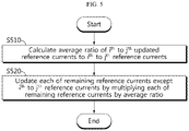
- FIG. 5 is a flowchart exemplarily showing a battery management method according to a second embodiment of the present disclosure.
- the method of FIG. 5 may be used to update each of the remaining reference currents. That is, the method of FIG. 5 may be performed when the battery B is charged over only part of the voltage range of V 0 ⁇ V n by the method of FIG. 4 .
- each of i and j is a natural number, i ⁇ j, and i is 2 or greater, or j is less than n (for example, 4).
- step S510 the control unit 140 calculates the average ratio of the i th to j th updated reference currents I 1i ⁇ I 1j to the i th to j th reference currents I i ⁇ I j (see ⁇ avg of the above equation).
- step S520 the control unit 140 updates each of the remaining reference currents except the i th to j th reference currents I i ⁇ I j among the first to n th reference currents I 1 ⁇ I n by multiplying each of the remaining reference currents by the average ratio.
Landscapes
- Engineering & Computer Science (AREA)
- Power Engineering (AREA)
- Manufacturing & Machinery (AREA)
- Chemical & Material Sciences (AREA)
- Chemical Kinetics & Catalysis (AREA)
- Electrochemistry (AREA)
- General Chemical & Material Sciences (AREA)
- Mechanical Engineering (AREA)
- Transportation (AREA)
- General Physics & Mathematics (AREA)
- Physics & Mathematics (AREA)
- Sustainable Development (AREA)
- Sustainable Energy (AREA)
- Life Sciences & Earth Sciences (AREA)
- Microelectronics & Electronic Packaging (AREA)
- Charge And Discharge Circuits For Batteries Or The Like (AREA)
- Secondary Cells (AREA)
- Electric Propulsion And Braking For Vehicles (AREA)
Applications Claiming Priority (2)
| Application Number | Priority Date | Filing Date | Title |
|---|---|---|---|
| KR1020200104883A KR102867900B1 (ko) | 2020-08-20 | 2020-08-20 | 배터리 관리 시스템, 배터리 관리 방법, 배터리 팩 및 전기 차량 |
| PCT/KR2021/010980 WO2022039505A1 (ko) | 2020-08-20 | 2021-08-18 | 배터리 관리 시스템, 배터리 관리 방법, 배터리 팩 및 전기 차량 |
Publications (2)
| Publication Number | Publication Date |
|---|---|
| EP4152472A1 true EP4152472A1 (de) | 2023-03-22 |
| EP4152472A4 EP4152472A4 (de) | 2023-12-06 |
Family
ID=80323077
Family Applications (1)
| Application Number | Title | Priority Date | Filing Date |
|---|---|---|---|
| EP21858592.5A Pending EP4152472A4 (de) | 2020-08-20 | 2021-08-18 | Batterieverwaltungssystem, batterieverwaltungsverfahren, batteriepack und elektrofahrzeug |
Country Status (6)
| Country | Link |
|---|---|
| US (1) | US12558990B2 (de) |
| EP (1) | EP4152472A4 (de) |
| JP (3) | JP7393090B2 (de) |
| KR (2) | KR102867900B1 (de) |
| CN (1) | CN115917831A (de) |
| WO (1) | WO2022039505A1 (de) |
Cited By (3)
| Publication number | Priority date | Publication date | Assignee | Title |
|---|---|---|---|---|
| EP4394998A4 (de) * | 2022-04-21 | 2025-06-25 | LG Energy Solution, Ltd. | Batteriesteuerungsvorrichtung und batteriesteuerungsverfahren |
| EP4564030A4 (de) * | 2023-05-31 | 2026-01-14 | Deepal Automobile Tech Co Ltd | Verfahren und vorrichtung zur schätzung der kapazität einer batteriezelle sowie server und speichermedium |
| EP4564028A4 (de) * | 2023-05-31 | 2026-01-21 | Deepal Automobile Tech Co Ltd | Schätzverfahren und -vorrichtung für soc einer batteriezelle sowie server und speichermedium |
Families Citing this family (3)
| Publication number | Priority date | Publication date | Assignee | Title |
|---|---|---|---|---|
| KR20210156618A (ko) * | 2020-06-18 | 2021-12-27 | 주식회사 엘지에너지솔루션 | 배터리 관리 시스템, 배터리 관리 방법, 배터리 팩 및 전기 차량 |
| KR102619695B1 (ko) * | 2022-04-21 | 2023-12-29 | 주식회사 엘지에너지솔루션 | 배터리 제어 장치 및 배터리 제어 방법 |
| CN118769971B (zh) * | 2024-06-13 | 2025-09-19 | 岚图汽车科技有限公司 | 充电剩余时间预测方法、装置和介质 |
Family Cites Families (29)
| Publication number | Priority date | Publication date | Assignee | Title |
|---|---|---|---|---|
| JPH07115733A (ja) | 1993-10-14 | 1995-05-02 | Toyota Autom Loom Works Ltd | バッテリー充電装置 |
| JP3620118B2 (ja) | 1995-10-24 | 2005-02-16 | 松下電器産業株式会社 | 定電流・定電圧充電装置 |
| KR101201110B1 (ko) | 2006-04-11 | 2012-11-13 | 삼성에스디아이 주식회사 | 전지 팩의 충전 장치 및 그 방법 |
| US7446505B2 (en) * | 2006-08-24 | 2008-11-04 | Symbol Technologies, Inc. | System and method for calculating a state of charge of a battery |
| JP4805863B2 (ja) | 2007-03-07 | 2011-11-02 | 長野日本無線株式会社 | 充電装置 |
| US8148938B2 (en) | 2009-05-28 | 2012-04-03 | Panasonic Corporation | Lead storage battery charging control method, charging control circuit, power source device, and lead storage battery |
| US8816648B2 (en) | 2009-08-17 | 2014-08-26 | Apple Inc. | Modulated, temperature-based multi-CC-CV charging technique for Li-ion/Li-polymer batteries |
| CN102474124B (zh) | 2009-11-20 | 2013-08-14 | 松下电器产业株式会社 | 充电控制电路、电池组件以及充电系统 |
| KR101288122B1 (ko) * | 2011-01-03 | 2013-07-18 | 삼성에스디아이 주식회사 | 배터리 충전방법, 및 이를 적용한 배터리 팩 |
| WO2012127775A1 (ja) | 2011-03-18 | 2012-09-27 | パナソニック株式会社 | 非水電解質二次電池の充電方法、及び電池パック |
| WO2015129032A1 (ja) | 2014-02-28 | 2015-09-03 | 株式会社日立製作所 | 蓄電池管理システムおよび蓄電池管理方法 |
| JP6145712B2 (ja) * | 2014-03-24 | 2017-06-14 | パナソニックIpマネジメント株式会社 | 二次電池の充電システム及び方法並びに電池パック |
| CN103935260B (zh) * | 2014-05-08 | 2015-10-28 | 山东大学 | 一种基于电池安全保护的电池管理方法 |
| KR102248599B1 (ko) * | 2014-05-20 | 2021-05-06 | 삼성에스디아이 주식회사 | 배터리의 충전방법 및 이를 위한 배터리 관리 시스템 |
| KR20170022778A (ko) * | 2015-08-21 | 2017-03-02 | 삼성에스디아이 주식회사 | 배터리의 충전 방법 및 이에 따른 배터리 팩 |
| KR101683181B1 (ko) | 2015-11-16 | 2016-12-08 | 주식회사 투엠아이 | 열적 안전성을 고려한 배터리의 급속 충전 시스템 및 방법 |
| KR20170062133A (ko) | 2015-11-27 | 2017-06-07 | 주식회사 엘지화학 | 배터리 충전방법 |
| KR101680324B1 (ko) | 2016-01-29 | 2016-11-28 | (주)에코파워텍 | 배터리 수명 판단장치 |
| KR102455631B1 (ko) | 2016-11-01 | 2022-10-18 | 삼성전자주식회사 | 배터리 충전 방법 및 장치 |
| US10985590B2 (en) | 2016-11-01 | 2021-04-20 | Samsung Electronics Co., Ltd. | Method and apparatus for charging battery |
| JP6442630B1 (ja) | 2018-01-24 | 2018-12-19 | 住友化学株式会社 | 非水電解液二次電池用負極活物質、負極及び電池 |
| JP6674502B2 (ja) * | 2018-05-22 | 2020-04-01 | 本田技研工業株式会社 | 充電制御装置 |
| JP7185692B2 (ja) * | 2018-05-31 | 2022-12-07 | オッポ広東移動通信有限公司 | 充電方法及び充電装置 |
| KR102259415B1 (ko) | 2018-08-29 | 2021-06-01 | 주식회사 엘지에너지솔루션 | 배터리 관리 장치, 배터리 관리 방법, 배터리 팩 및 전기 차량 |
| KR102351637B1 (ko) | 2018-09-12 | 2022-01-14 | 주식회사 엘지에너지솔루션 | 배터리 관리 장치 및 방법 |
| JP2020046332A (ja) | 2018-09-20 | 2020-03-26 | 株式会社ケーヒン | バッテリ監視装置 |
| KR102392399B1 (ko) * | 2018-12-21 | 2022-04-28 | 주식회사 엘지에너지솔루션 | 이차 전지의 스텝 충전 제어 장치 및 방법 |
| JP7182476B2 (ja) | 2019-01-21 | 2022-12-02 | 株式会社日立製作所 | 二次電池モジュールの余寿命診断方法及び余寿命診断システム |
| KR102772378B1 (ko) * | 2020-08-13 | 2025-02-21 | 주식회사 엘지에너지솔루션 | 배터리 관리 시스템, 배터리 관리 방법, 배터리 팩 및 전기 차량 |
-
2020
- 2020-08-20 KR KR1020200104883A patent/KR102867900B1/ko active Active
-
2021
- 2021-08-18 EP EP21858592.5A patent/EP4152472A4/de active Pending
- 2021-08-18 WO PCT/KR2021/010980 patent/WO2022039505A1/ko not_active Ceased
- 2021-08-18 US US18/005,787 patent/US12558990B2/en active Active
- 2021-08-18 JP JP2022570421A patent/JP7393090B2/ja active Active
- 2021-08-18 CN CN202180044237.8A patent/CN115917831A/zh active Pending
-
2023
- 2023-11-21 JP JP2023197255A patent/JP7669452B2/ja active Active
-
2025
- 2025-04-15 JP JP2025067148A patent/JP7832393B2/ja active Active
- 2025-09-19 KR KR1020250135086A patent/KR20250141676A/ko active Pending
Cited By (4)
| Publication number | Priority date | Publication date | Assignee | Title |
|---|---|---|---|---|
| EP4394998A4 (de) * | 2022-04-21 | 2025-06-25 | LG Energy Solution, Ltd. | Batteriesteuerungsvorrichtung und batteriesteuerungsverfahren |
| US12500435B2 (en) | 2022-04-21 | 2025-12-16 | Lg Energy Solution, Ltd. | Battery control apparatus and battery control method |
| EP4564030A4 (de) * | 2023-05-31 | 2026-01-14 | Deepal Automobile Tech Co Ltd | Verfahren und vorrichtung zur schätzung der kapazität einer batteriezelle sowie server und speichermedium |
| EP4564028A4 (de) * | 2023-05-31 | 2026-01-21 | Deepal Automobile Tech Co Ltd | Schätzverfahren und -vorrichtung für soc einer batteriezelle sowie server und speichermedium |
Also Published As
| Publication number | Publication date |
|---|---|
| KR102867900B1 (ko) | 2025-10-01 |
| JP7393090B2 (ja) | 2023-12-06 |
| CN115917831A (zh) | 2023-04-04 |
| JP2023527515A (ja) | 2023-06-29 |
| WO2022039505A1 (ko) | 2022-02-24 |
| US20230278459A1 (en) | 2023-09-07 |
| JP2025111534A (ja) | 2025-07-30 |
| US12558990B2 (en) | 2026-02-24 |
| KR20220023244A (ko) | 2022-03-02 |
| JP7669452B2 (ja) | 2025-04-28 |
| JP7832393B2 (ja) | 2026-03-17 |
| JP2024020488A (ja) | 2024-02-14 |
| KR20250141676A (ko) | 2025-09-29 |
| EP4152472A4 (de) | 2023-12-06 |
Similar Documents
| Publication | Publication Date | Title |
|---|---|---|
| US12523707B2 (en) | Battery management system, battery management method, battery pack, and electric vehicle | |
| US12370922B2 (en) | Battery management apparatus, battery management method, battery pack, and electric vehicle | |
| US12558990B2 (en) | Battery management system, battery management method, battery pack, and electric vehicle | |
| US12007449B2 (en) | Battery management apparatus, battery management method, battery pack and electric vehicle | |
| US11460506B2 (en) | Apparatus and method for determining differential voltage curve of battery and battery pack comprising the apparatus | |
| EP4166956A1 (de) | Batteriediagnosevorrichtung, batteriediagnoseverfahren, batteriepack und elektrofahrzeug | |
| EP4068562A1 (de) | Batterieverwaltungsvorrichtung, batterieverwaltungsverfahren, batteriepack und elektrofahrzeug | |
| EP4180826B1 (de) | Batteriediagnosevorrichtung, batteriediagnoseverfahren, batteriepack und elektrofahrzeug | |
| US12344120B2 (en) | Battery management system, battery management method, battery pack, and electric vehicle | |
| US20260048680A1 (en) | Battery Management System, Battery Management Method, Battery Pack, and Electric Vehicle | |
| KR102949561B1 (ko) | 배터리 진단 장치 및 배터리 진단 방법 | |
| EP4729970A1 (de) | Batteriediagnosevorrichtung und batteriediagnoseverfahren |
Legal Events
| Date | Code | Title | Description |
|---|---|---|---|
| STAA | Information on the status of an ep patent application or granted ep patent |
Free format text: STATUS: THE INTERNATIONAL PUBLICATION HAS BEEN MADE |
|
| PUAI | Public reference made under article 153(3) epc to a published international application that has entered the european phase |
Free format text: ORIGINAL CODE: 0009012 |
|
| STAA | Information on the status of an ep patent application or granted ep patent |
Free format text: STATUS: REQUEST FOR EXAMINATION WAS MADE |
|
| 17P | Request for examination filed |
Effective date: 20221214 |
|
| AK | Designated contracting states |
Kind code of ref document: A1 Designated state(s): AL AT BE BG CH CY CZ DE DK EE ES FI FR GB GR HR HU IE IS IT LI LT LU LV MC MK MT NL NO PL PT RO RS SE SI SK SM TR |
|
| DAV | Request for validation of the european patent (deleted) | ||
| DAX | Request for extension of the european patent (deleted) | ||
| A4 | Supplementary search report drawn up and despatched |
Effective date: 20231107 |
|
| RIC1 | Information provided on ipc code assigned before grant |
Ipc: H02J 7/00 20060101ALI20231031BHEP Ipc: H01M 10/44 20060101ALI20231031BHEP Ipc: H01M 10/052 20100101ALI20231031BHEP Ipc: B60L 53/66 20190101ALI20231031BHEP Ipc: G01R 31/387 20190101ALI20231031BHEP Ipc: G01R 31/396 20190101ALI20231031BHEP Ipc: B60L 58/12 20190101ALI20231031BHEP Ipc: H01M 10/48 20060101ALI20231031BHEP Ipc: H01M 10/42 20060101AFI20231031BHEP |