EP4152506A1 - Structure de séparateur, son procédé de fabrication et batterie secondaire utilisant celle-ci - Google Patents
Structure de séparateur, son procédé de fabrication et batterie secondaire utilisant celle-ci Download PDFInfo
- Publication number
- EP4152506A1 EP4152506A1 EP21805248.8A EP21805248A EP4152506A1 EP 4152506 A1 EP4152506 A1 EP 4152506A1 EP 21805248 A EP21805248 A EP 21805248A EP 4152506 A1 EP4152506 A1 EP 4152506A1
- Authority
- EP
- European Patent Office
- Prior art keywords
- nano fiber
- cellulose nano
- separator
- separator structure
- group
- Prior art date
- Legal status (The legal status is an assumption and is not a legal conclusion. Google has not performed a legal analysis and makes no representation as to the accuracy of the status listed.)
- Pending
Links
- 238000004519 manufacturing process Methods 0.000 title abstract description 3
- 229920002678 cellulose Polymers 0.000 claims description 217
- 239000001913 cellulose Substances 0.000 claims description 217
- 239000002121 nanofiber Substances 0.000 claims description 217
- 238000000576 coating method Methods 0.000 claims description 117
- 239000011248 coating agent Substances 0.000 claims description 104
- 239000010954 inorganic particle Substances 0.000 claims description 83
- 238000000034 method Methods 0.000 claims description 62
- 238000004381 surface treatment Methods 0.000 claims description 48
- 239000011230 binding agent Substances 0.000 claims description 44
- 239000002131 composite material Substances 0.000 claims description 41
- 125000000524 functional group Chemical group 0.000 claims description 41
- VYPSYNLAJGMNEJ-UHFFFAOYSA-N Silicium dioxide Chemical compound O=[Si]=O VYPSYNLAJGMNEJ-UHFFFAOYSA-N 0.000 claims description 16
- GWEVSGVZZGPLCZ-UHFFFAOYSA-N Titan oxide Chemical compound O=[Ti]=O GWEVSGVZZGPLCZ-UHFFFAOYSA-N 0.000 claims description 16
- XOLBLPGZBRYERU-UHFFFAOYSA-N tin dioxide Chemical compound O=[Sn]=O XOLBLPGZBRYERU-UHFFFAOYSA-N 0.000 claims description 16
- 238000006243 chemical reaction Methods 0.000 claims description 9
- PNEYBMLMFCGWSK-UHFFFAOYSA-N aluminium oxide Inorganic materials [O-2].[O-2].[O-2].[Al+3].[Al+3] PNEYBMLMFCGWSK-UHFFFAOYSA-N 0.000 claims description 8
- 229910002113 barium titanate Inorganic materials 0.000 claims description 8
- 229910052681 coesite Inorganic materials 0.000 claims description 8
- 229910052593 corundum Inorganic materials 0.000 claims description 8
- 229910052906 cristobalite Inorganic materials 0.000 claims description 8
- 239000000377 silicon dioxide Substances 0.000 claims description 8
- 229910052682 stishovite Inorganic materials 0.000 claims description 8
- 229910052905 tridymite Inorganic materials 0.000 claims description 8
- 229910001845 yogo sapphire Inorganic materials 0.000 claims description 8
- 125000003277 amino group Chemical group 0.000 claims description 7
- 125000003178 carboxy group Chemical group [H]OC(*)=O 0.000 claims description 7
- 239000003792 electrolyte Substances 0.000 claims description 7
- 239000002245 particle Substances 0.000 claims description 7
- 150000002500 ions Chemical class 0.000 abstract description 38
- HBBGRARXTFLTSG-UHFFFAOYSA-N Lithium ion Chemical compound [Li+] HBBGRARXTFLTSG-UHFFFAOYSA-N 0.000 abstract description 4
- 229910001416 lithium ion Inorganic materials 0.000 abstract description 4
- 239000000835 fiber Substances 0.000 abstract description 3
- 229920001046 Nanocellulose Polymers 0.000 abstract description 2
- 239000000243 solution Substances 0.000 description 50
- XLYOFNOQVPJJNP-UHFFFAOYSA-N water Substances O XLYOFNOQVPJJNP-UHFFFAOYSA-N 0.000 description 49
- 239000011247 coating layer Substances 0.000 description 48
- 230000008569 process Effects 0.000 description 47
- 239000006185 dispersion Substances 0.000 description 37
- 239000003960 organic solvent Substances 0.000 description 33
- 239000002904 solvent Substances 0.000 description 33
- 239000010410 layer Substances 0.000 description 24
- 239000000203 mixture Substances 0.000 description 23
- 238000002360 preparation method Methods 0.000 description 21
- 230000008602 contraction Effects 0.000 description 20
- HEMHJVSKTPXQMS-UHFFFAOYSA-M Sodium hydroxide Chemical compound [OH-].[Na+] HEMHJVSKTPXQMS-UHFFFAOYSA-M 0.000 description 18
- 229920000098 polyolefin Polymers 0.000 description 17
- 239000004744 fabric Substances 0.000 description 16
- CSCPPACGZOOCGX-UHFFFAOYSA-N Acetone Chemical compound CC(C)=O CSCPPACGZOOCGX-UHFFFAOYSA-N 0.000 description 12
- LFQSCWFLJHTTHZ-UHFFFAOYSA-N Ethanol Chemical compound CCO LFQSCWFLJHTTHZ-UHFFFAOYSA-N 0.000 description 12
- 239000008367 deionised water Substances 0.000 description 12
- 229910021641 deionized water Inorganic materials 0.000 description 12
- BFSVOASYOCHEOV-UHFFFAOYSA-N 2-diethylaminoethanol Chemical compound CCN(CC)CCO BFSVOASYOCHEOV-UHFFFAOYSA-N 0.000 description 11
- 125000002091 cationic group Chemical group 0.000 description 11
- 238000004833 X-ray photoelectron spectroscopy Methods 0.000 description 10
- 238000010586 diagram Methods 0.000 description 10
- PUVAFTRIIUSGLK-UHFFFAOYSA-M trimethyl(oxiran-2-ylmethyl)azanium;chloride Chemical compound [Cl-].C[N+](C)(C)CC1CO1 PUVAFTRIIUSGLK-UHFFFAOYSA-M 0.000 description 10
- 238000002156 mixing Methods 0.000 description 9
- 239000002002 slurry Substances 0.000 description 9
- 125000000129 anionic group Chemical group 0.000 description 8
- 125000002057 carboxymethyl group Chemical group [H]OC(=O)C([H])([H])[*] 0.000 description 7
- 230000000694 effects Effects 0.000 description 7
- -1 polyethylene Polymers 0.000 description 7
- 239000007864 aqueous solution Substances 0.000 description 6
- 238000009835 boiling Methods 0.000 description 6
- 238000007607 die coating method Methods 0.000 description 6
- 238000003618 dip coating Methods 0.000 description 6
- 238000007756 gravure coating Methods 0.000 description 6
- 230000035699 permeability Effects 0.000 description 6
- 239000000843 powder Substances 0.000 description 6
- 238000004626 scanning electron microscopy Methods 0.000 description 6
- 239000002704 solution binder Substances 0.000 description 6
- 239000002033 PVDF binder Substances 0.000 description 5
- 239000004698 Polyethylene Substances 0.000 description 5
- 239000004743 Polypropylene Substances 0.000 description 5
- 229920000573 polyethylene Polymers 0.000 description 5
- 229920005596 polymer binder Polymers 0.000 description 5
- 239000002491 polymer binding agent Substances 0.000 description 5
- 229920001155 polypropylene Polymers 0.000 description 5
- IJGRMHOSHXDMSA-UHFFFAOYSA-N Atomic nitrogen Chemical compound N#N IJGRMHOSHXDMSA-UHFFFAOYSA-N 0.000 description 4
- 238000002441 X-ray diffraction Methods 0.000 description 4
- 238000000026 X-ray photoelectron spectrum Methods 0.000 description 4
- NIXOWILDQLNWCW-UHFFFAOYSA-N acrylic acid group Chemical group C(C=C)(=O)O NIXOWILDQLNWCW-UHFFFAOYSA-N 0.000 description 4
- 229910052782 aluminium Inorganic materials 0.000 description 4
- 150000001450 anions Chemical class 0.000 description 4
- 150000001768 cations Chemical class 0.000 description 4
- 210000004027 cell Anatomy 0.000 description 4
- 230000018044 dehydration Effects 0.000 description 4
- 238000006297 dehydration reaction Methods 0.000 description 4
- 238000000227 grinding Methods 0.000 description 4
- 238000005470 impregnation Methods 0.000 description 4
- 229910052757 nitrogen Inorganic materials 0.000 description 4
- 239000002952 polymeric resin Substances 0.000 description 4
- 229920002981 polyvinylidene fluoride Polymers 0.000 description 4
- 239000011148 porous material Substances 0.000 description 4
- 239000002994 raw material Substances 0.000 description 4
- 229920003002 synthetic resin Polymers 0.000 description 4
- RAGSWDIQBBZLLL-UHFFFAOYSA-N 2-chloroethyl(diethyl)azanium;chloride Chemical compound Cl.CCN(CC)CCCl RAGSWDIQBBZLLL-UHFFFAOYSA-N 0.000 description 3
- 239000011149 active material Substances 0.000 description 3
- 230000001668 ameliorated effect Effects 0.000 description 3
- 238000004458 analytical method Methods 0.000 description 3
- 238000000498 ball milling Methods 0.000 description 3
- 230000008901 benefit Effects 0.000 description 3
- 229910052799 carbon Inorganic materials 0.000 description 3
- IEJIGPNLZYLLBP-UHFFFAOYSA-N dimethyl carbonate Chemical compound COC(=O)OC IEJIGPNLZYLLBP-UHFFFAOYSA-N 0.000 description 3
- 239000012535 impurity Substances 0.000 description 3
- 229910052760 oxygen Inorganic materials 0.000 description 3
- 238000001228 spectrum Methods 0.000 description 3
- RYGMFSIKBFXOCR-UHFFFAOYSA-N Copper Chemical compound [Cu] RYGMFSIKBFXOCR-UHFFFAOYSA-N 0.000 description 2
- KMTRUDSVKNLOMY-UHFFFAOYSA-N Ethylene carbonate Chemical compound O=C1OCCO1 KMTRUDSVKNLOMY-UHFFFAOYSA-N 0.000 description 2
- 238000001157 Fourier transform infrared spectrum Methods 0.000 description 2
- QYTDEUPAUMOIOP-UHFFFAOYSA-N TEMPO Chemical group CC1(C)CCCC(C)(C)N1[O] QYTDEUPAUMOIOP-UHFFFAOYSA-N 0.000 description 2
- XAGFODPZIPBFFR-UHFFFAOYSA-N aluminium Chemical compound [Al] XAGFODPZIPBFFR-UHFFFAOYSA-N 0.000 description 2
- 238000004630 atomic force microscopy Methods 0.000 description 2
- 238000005341 cation exchange Methods 0.000 description 2
- 239000003153 chemical reaction reagent Substances 0.000 description 2
- 229910052801 chlorine Inorganic materials 0.000 description 2
- 238000010924 continuous production Methods 0.000 description 2
- 230000007423 decrease Effects 0.000 description 2
- 238000009826 distribution Methods 0.000 description 2
- 238000004880 explosion Methods 0.000 description 2
- 239000011121 hardwood Substances 0.000 description 2
- 230000002209 hydrophobic effect Effects 0.000 description 2
- 230000005661 hydrophobic surface Effects 0.000 description 2
- 229910003002 lithium salt Inorganic materials 0.000 description 2
- 159000000002 lithium salts Chemical class 0.000 description 2
- 239000012528 membrane Substances 0.000 description 2
- 239000011259 mixed solution Substances 0.000 description 2
- 239000007773 negative electrode material Substances 0.000 description 2
- 239000004417 polycarbonate Substances 0.000 description 2
- 229920000515 polycarbonate Polymers 0.000 description 2
- RUOJZAUFBMNUDX-UHFFFAOYSA-N propylene carbonate Chemical compound CC1COC(=O)O1 RUOJZAUFBMNUDX-UHFFFAOYSA-N 0.000 description 2
- 229910052710 silicon Inorganic materials 0.000 description 2
- FDRCDNZGSXJAFP-UHFFFAOYSA-M sodium chloroacetate Chemical compound [Na+].[O-]C(=O)CCl FDRCDNZGSXJAFP-UHFFFAOYSA-M 0.000 description 2
- 235000017166 Bambusa arundinacea Nutrition 0.000 description 1
- 235000017491 Bambusa tulda Nutrition 0.000 description 1
- 241001330002 Bambuseae Species 0.000 description 1
- 241000196324 Embryophyta Species 0.000 description 1
- 229910000552 LiCF3SO3 Inorganic materials 0.000 description 1
- 229910001290 LiPF6 Inorganic materials 0.000 description 1
- 235000015334 Phyllostachys viridis Nutrition 0.000 description 1
- 238000010521 absorption reaction Methods 0.000 description 1
- 239000000654 additive Substances 0.000 description 1
- 230000000996 additive effect Effects 0.000 description 1
- 238000004026 adhesive bonding Methods 0.000 description 1
- 229910021383 artificial graphite Inorganic materials 0.000 description 1
- 239000011425 bamboo Substances 0.000 description 1
- 239000011324 bead Substances 0.000 description 1
- 238000010009 beating Methods 0.000 description 1
- 230000000903 blocking effect Effects 0.000 description 1
- 210000002421 cell wall Anatomy 0.000 description 1
- FOCAUTSVDIKZOP-UHFFFAOYSA-N chloroacetic acid Chemical compound OC(=O)CCl FOCAUTSVDIKZOP-UHFFFAOYSA-N 0.000 description 1
- 229940106681 chloroacetic acid Drugs 0.000 description 1
- 239000004020 conductor Substances 0.000 description 1
- 229910052802 copper Inorganic materials 0.000 description 1
- 239000010949 copper Substances 0.000 description 1
- 239000011889 copper foil Substances 0.000 description 1
- 239000013078 crystal Substances 0.000 description 1
- 230000006866 deterioration Effects 0.000 description 1
- 238000009792 diffusion process Methods 0.000 description 1
- 239000012153 distilled water Substances 0.000 description 1
- 238000001035 drying Methods 0.000 description 1
- 238000005516 engineering process Methods 0.000 description 1
- JBTWLSYIZRCDFO-UHFFFAOYSA-N ethyl methyl carbonate Chemical compound CCOC(=O)OC JBTWLSYIZRCDFO-UHFFFAOYSA-N 0.000 description 1
- 238000011156 evaluation Methods 0.000 description 1
- 230000001747 exhibiting effect Effects 0.000 description 1
- 238000011049 filling Methods 0.000 description 1
- 239000003365 glass fiber Substances 0.000 description 1
- 230000006872 improvement Effects 0.000 description 1
- 238000002347 injection Methods 0.000 description 1
- 239000007924 injection Substances 0.000 description 1
- 239000011244 liquid electrolyte Substances 0.000 description 1
- 229910001540 lithium hexafluoroarsenate(V) Inorganic materials 0.000 description 1
- 229910001486 lithium perchlorate Inorganic materials 0.000 description 1
- MHCFAGZWMAWTNR-UHFFFAOYSA-M lithium perchlorate Chemical compound [Li+].[O-]Cl(=O)(=O)=O MHCFAGZWMAWTNR-UHFFFAOYSA-M 0.000 description 1
- 229910001496 lithium tetrafluoroborate Inorganic materials 0.000 description 1
- 239000000463 material Substances 0.000 description 1
- 229910052751 metal Inorganic materials 0.000 description 1
- 239000002184 metal Substances 0.000 description 1
- GDOPTJXRTPNYNR-UHFFFAOYSA-N methyl-cyclopentane Natural products CC1CCCC1 GDOPTJXRTPNYNR-UHFFFAOYSA-N 0.000 description 1
- 230000004048 modification Effects 0.000 description 1
- 238000012986 modification Methods 0.000 description 1
- 239000002086 nanomaterial Substances 0.000 description 1
- 229910021382 natural graphite Inorganic materials 0.000 description 1
- 230000007935 neutral effect Effects 0.000 description 1
- 239000011146 organic particle Substances 0.000 description 1
- 239000004014 plasticizer Substances 0.000 description 1
- 229920000642 polymer Polymers 0.000 description 1
- 239000007774 positive electrode material Substances 0.000 description 1
- 235000012239 silicon dioxide Nutrition 0.000 description 1
- 239000007784 solid electrolyte Substances 0.000 description 1
- 238000010183 spectrum analysis Methods 0.000 description 1
- 238000003756 stirring Methods 0.000 description 1
- 239000000758 substrate Substances 0.000 description 1
- 239000004094 surface-active agent Substances 0.000 description 1
- 238000005406 washing Methods 0.000 description 1
Images








Classifications
-
- H—ELECTRICITY
- H01—ELECTRIC ELEMENTS
- H01M—PROCESSES OR MEANS, e.g. BATTERIES, FOR THE DIRECT CONVERSION OF CHEMICAL ENERGY INTO ELECTRICAL ENERGY
- H01M50/00—Constructional details or processes of manufacture of the non-active parts of electrochemical cells other than fuel cells, e.g. hybrid cells
- H01M50/40—Separators; Membranes; Diaphragms; Spacing elements inside cells
- H01M50/409—Separators, membranes or diaphragms characterised by the material
- H01M50/411—Organic material
- H01M50/429—Natural polymers
- H01M50/4295—Natural cotton, cellulose or wood
-
- H—ELECTRICITY
- H01—ELECTRIC ELEMENTS
- H01M—PROCESSES OR MEANS, e.g. BATTERIES, FOR THE DIRECT CONVERSION OF CHEMICAL ENERGY INTO ELECTRICAL ENERGY
- H01M10/00—Secondary cells; Manufacture thereof
- H01M10/05—Accumulators with non-aqueous electrolyte
- H01M10/056—Accumulators with non-aqueous electrolyte characterised by the materials used as electrolytes, e.g. mixed inorganic/organic electrolytes
-
- B—PERFORMING OPERATIONS; TRANSPORTING
- B01—PHYSICAL OR CHEMICAL PROCESSES OR APPARATUS IN GENERAL
- B01D—SEPARATION
- B01D67/00—Processes specially adapted for manufacturing semi-permeable membranes for separation processes or apparatus
- B01D67/0081—After-treatment of organic or inorganic membranes
- B01D67/0093—Chemical modification
-
- B—PERFORMING OPERATIONS; TRANSPORTING
- B01—PHYSICAL OR CHEMICAL PROCESSES OR APPARATUS IN GENERAL
- B01D—SEPARATION
- B01D71/00—Semi-permeable membranes for separation processes or apparatus characterised by the material; Manufacturing processes specially adapted therefor
- B01D71/02—Inorganic material
-
- B—PERFORMING OPERATIONS; TRANSPORTING
- B01—PHYSICAL OR CHEMICAL PROCESSES OR APPARATUS IN GENERAL
- B01D—SEPARATION
- B01D71/00—Semi-permeable membranes for separation processes or apparatus characterised by the material; Manufacturing processes specially adapted therefor
- B01D71/06—Organic material
- B01D71/08—Polysaccharides
- B01D71/10—Cellulose; Modified cellulose
-
- B—PERFORMING OPERATIONS; TRANSPORTING
- B01—PHYSICAL OR CHEMICAL PROCESSES OR APPARATUS IN GENERAL
- B01D—SEPARATION
- B01D71/00—Semi-permeable membranes for separation processes or apparatus characterised by the material; Manufacturing processes specially adapted therefor
- B01D71/06—Organic material
- B01D71/26—Polyalkenes
-
- C—CHEMISTRY; METALLURGY
- C09—DYES; PAINTS; POLISHES; NATURAL RESINS; ADHESIVES; COMPOSITIONS NOT OTHERWISE PROVIDED FOR; APPLICATIONS OF MATERIALS NOT OTHERWISE PROVIDED FOR
- C09D—COATING COMPOSITIONS, e.g. PAINTS, VARNISHES OR LACQUERS; FILLING PASTES; CHEMICAL PAINT OR INK REMOVERS; INKS; CORRECTING FLUIDS; WOODSTAINS; PASTES OR SOLIDS FOR COLOURING OR PRINTING; USE OF MATERIALS THEREFOR
- C09D101/00—Coating compositions based on cellulose, modified cellulose, or cellulose derivatives
- C09D101/08—Cellulose derivatives
-
- C—CHEMISTRY; METALLURGY
- C09—DYES; PAINTS; POLISHES; NATURAL RESINS; ADHESIVES; COMPOSITIONS NOT OTHERWISE PROVIDED FOR; APPLICATIONS OF MATERIALS NOT OTHERWISE PROVIDED FOR
- C09D—COATING COMPOSITIONS, e.g. PAINTS, VARNISHES OR LACQUERS; FILLING PASTES; CHEMICAL PAINT OR INK REMOVERS; INKS; CORRECTING FLUIDS; WOODSTAINS; PASTES OR SOLIDS FOR COLOURING OR PRINTING; USE OF MATERIALS THEREFOR
- C09D7/00—Features of coating compositions, not provided for in group C09D5/00; Processes for incorporating ingredients in coating compositions
- C09D7/40—Additives
- C09D7/65—Additives macromolecular
-
- H—ELECTRICITY
- H01—ELECTRIC ELEMENTS
- H01M—PROCESSES OR MEANS, e.g. BATTERIES, FOR THE DIRECT CONVERSION OF CHEMICAL ENERGY INTO ELECTRICAL ENERGY
- H01M50/00—Constructional details or processes of manufacture of the non-active parts of electrochemical cells other than fuel cells, e.g. hybrid cells
- H01M50/40—Separators; Membranes; Diaphragms; Spacing elements inside cells
- H01M50/403—Manufacturing processes of separators, membranes or diaphragms
-
- H—ELECTRICITY
- H01—ELECTRIC ELEMENTS
- H01M—PROCESSES OR MEANS, e.g. BATTERIES, FOR THE DIRECT CONVERSION OF CHEMICAL ENERGY INTO ELECTRICAL ENERGY
- H01M50/00—Constructional details or processes of manufacture of the non-active parts of electrochemical cells other than fuel cells, e.g. hybrid cells
- H01M50/40—Separators; Membranes; Diaphragms; Spacing elements inside cells
- H01M50/409—Separators, membranes or diaphragms characterised by the material
- H01M50/431—Inorganic material
-
- H—ELECTRICITY
- H01—ELECTRIC ELEMENTS
- H01M—PROCESSES OR MEANS, e.g. BATTERIES, FOR THE DIRECT CONVERSION OF CHEMICAL ENERGY INTO ELECTRICAL ENERGY
- H01M50/00—Constructional details or processes of manufacture of the non-active parts of electrochemical cells other than fuel cells, e.g. hybrid cells
- H01M50/40—Separators; Membranes; Diaphragms; Spacing elements inside cells
- H01M50/409—Separators, membranes or diaphragms characterised by the material
- H01M50/44—Fibrous material
-
- H—ELECTRICITY
- H01—ELECTRIC ELEMENTS
- H01M—PROCESSES OR MEANS, e.g. BATTERIES, FOR THE DIRECT CONVERSION OF CHEMICAL ENERGY INTO ELECTRICAL ENERGY
- H01M50/00—Constructional details or processes of manufacture of the non-active parts of electrochemical cells other than fuel cells, e.g. hybrid cells
- H01M50/40—Separators; Membranes; Diaphragms; Spacing elements inside cells
- H01M50/409—Separators, membranes or diaphragms characterised by the material
- H01M50/443—Particulate material
-
- H—ELECTRICITY
- H01—ELECTRIC ELEMENTS
- H01M—PROCESSES OR MEANS, e.g. BATTERIES, FOR THE DIRECT CONVERSION OF CHEMICAL ENERGY INTO ELECTRICAL ENERGY
- H01M50/00—Constructional details or processes of manufacture of the non-active parts of electrochemical cells other than fuel cells, e.g. hybrid cells
- H01M50/40—Separators; Membranes; Diaphragms; Spacing elements inside cells
- H01M50/409—Separators, membranes or diaphragms characterised by the material
- H01M50/446—Composite material consisting of a mixture of organic and inorganic materials
-
- H—ELECTRICITY
- H01—ELECTRIC ELEMENTS
- H01M—PROCESSES OR MEANS, e.g. BATTERIES, FOR THE DIRECT CONVERSION OF CHEMICAL ENERGY INTO ELECTRICAL ENERGY
- H01M50/00—Constructional details or processes of manufacture of the non-active parts of electrochemical cells other than fuel cells, e.g. hybrid cells
- H01M50/40—Separators; Membranes; Diaphragms; Spacing elements inside cells
- H01M50/409—Separators, membranes or diaphragms characterised by the material
- H01M50/449—Separators, membranes or diaphragms characterised by the material having a layered structure
-
- H—ELECTRICITY
- H01—ELECTRIC ELEMENTS
- H01M—PROCESSES OR MEANS, e.g. BATTERIES, FOR THE DIRECT CONVERSION OF CHEMICAL ENERGY INTO ELECTRICAL ENERGY
- H01M50/00—Constructional details or processes of manufacture of the non-active parts of electrochemical cells other than fuel cells, e.g. hybrid cells
- H01M50/40—Separators; Membranes; Diaphragms; Spacing elements inside cells
- H01M50/489—Separators, membranes, diaphragms or spacing elements inside the cells, characterised by their physical properties, e.g. swelling degree, hydrophilicity or shut down properties
-
- H—ELECTRICITY
- H01—ELECTRIC ELEMENTS
- H01M—PROCESSES OR MEANS, e.g. BATTERIES, FOR THE DIRECT CONVERSION OF CHEMICAL ENERGY INTO ELECTRICAL ENERGY
- H01M2300/00—Electrolytes
- H01M2300/0017—Non-aqueous electrolytes
- H01M2300/002—Inorganic electrolyte
- H01M2300/0022—Room temperature molten salts
-
- H—ELECTRICITY
- H01—ELECTRIC ELEMENTS
- H01M—PROCESSES OR MEANS, e.g. BATTERIES, FOR THE DIRECT CONVERSION OF CHEMICAL ENERGY INTO ELECTRICAL ENERGY
- H01M2300/00—Electrolytes
- H01M2300/0017—Non-aqueous electrolytes
- H01M2300/0025—Organic electrolyte
- H01M2300/0028—Organic electrolyte characterised by the solvent
- H01M2300/0037—Mixture of solvents
-
- Y—GENERAL TAGGING OF NEW TECHNOLOGICAL DEVELOPMENTS; GENERAL TAGGING OF CROSS-SECTIONAL TECHNOLOGIES SPANNING OVER SEVERAL SECTIONS OF THE IPC; TECHNICAL SUBJECTS COVERED BY FORMER USPC CROSS-REFERENCE ART COLLECTIONS [XRACs] AND DIGESTS
- Y02—TECHNOLOGIES OR APPLICATIONS FOR MITIGATION OR ADAPTATION AGAINST CLIMATE CHANGE
- Y02E—REDUCTION OF GREENHOUSE GAS [GHG] EMISSIONS, RELATED TO ENERGY GENERATION, TRANSMISSION OR DISTRIBUTION
- Y02E60/00—Enabling technologies; Technologies with a potential or indirect contribution to GHG emissions mitigation
- Y02E60/10—Energy storage using batteries
-
- Y—GENERAL TAGGING OF NEW TECHNOLOGICAL DEVELOPMENTS; GENERAL TAGGING OF CROSS-SECTIONAL TECHNOLOGIES SPANNING OVER SEVERAL SECTIONS OF THE IPC; TECHNICAL SUBJECTS COVERED BY FORMER USPC CROSS-REFERENCE ART COLLECTIONS [XRACs] AND DIGESTS
- Y02—TECHNOLOGIES OR APPLICATIONS FOR MITIGATION OR ADAPTATION AGAINST CLIMATE CHANGE
- Y02P—CLIMATE CHANGE MITIGATION TECHNOLOGIES IN THE PRODUCTION OR PROCESSING OF GOODS
- Y02P70/00—Climate change mitigation technologies in the production process for final industrial or consumer products
- Y02P70/50—Manufacturing or production processes characterised by the final manufactured product
Definitions
- the present disclosure is applicable to the technical field related to a secondary battery, and relates to, for example, a separator structure for the secondary battery, a method for preparing the same, and the secondary battery using the same.
- Secondary batteries including a lithium-ion battery require a relatively high operating temperature range compared to other batteries because a temperature thereof rises as a state of being continuously charged/discharged is maintained while being used.
- secondary batteries for a vehicle including the lithium-ion battery require a higher operating temperature range because an amount of charge/discharge is relatively greater than that of other batteries as a high capacity and a high output are required. Therefore, a separator used in such secondary batteries for the vehicle is required to have higher heat resistance and thermal stability than those required by a normal separator.
- the polymer binder is used to secure adhesion between the inorganic particles and the polyolefin-based separator support body. Because of deterioration of the polymer binder at a high temperatures, the inorganic particles are eliminated, so that there is a limit in terms of thermal contraction at a temperature equal to or higher than 150 °C. Therefore, mechanical properties such as the adhesion of the inorganic particles is also important.
- the present disclosure is to provide a separator structure, a method for preparing the same, and a secondary battery using the same that may significantly reduce a thermal contraction percentage at a high temperature and thus improve heat resistance, and at the same time realize a function of closing (shut down) the separator.
- the present disclosure intends to provide a separator structure, a method for preparing the same, and a secondary battery using the same that may secure adhesion between a support body and a coating layer
- the present disclosure is to provide a separator structure, a method for preparing the same, and a secondary battery using the same that may be harmless to an environment and may be prepared in a low-temperature aqueous solution.
- a first aspect of the present disclosure provides a separator structure disposed inside a secondary battery including a porous support body including a first face and a second face, and a cellulose nano fiber subjected to an ionic surface treatment located on at least one of the first face and the second face of the support body.
- the cellulose nano fiber subjected to the ionic surface treatment may be a cellulose nano fiber with an ionic functional group given thereto.
- the ionic functional group may improve affinity between the cellulose nano fiber and the support body.
- a reaction amount of the ionic functional group to the cellulose nano fiber may be in a range from 5 to 30 %.
- the separator structure may further contain inorganic particles at least partially in contact with the cellulose nano fiber.
- the inorganic particles may form a network with the cellulose nano fiber.
- the inorganic particles may include at least one selected from a group consisting of Al 2 O 3 , BaTiO 3 , SiO 2 , TiO 2 , and SnO 2 .
- the cellulose nano fiber subjected to the ionic surface treatment may have a positive ion group, a negative ion group, or a zwitterionic group.
- the positive ion group may include an amine group.
- the negative ion group may include a carboxyl group.
- the separator structure may further contain a binder for attaching the cellulose nano fiber on at least one of the first face and the second face of the support body.
- the cellulose nano fiber may have a crystallinity in a range from 40 to 60 %.
- a second aspect of the present disclosure provides a separator structure including a support body having at least one face coated with a dry coating composite, wherein the dry coating composite contains 1 to 10 wt% of a cellulose nano fiber with an ionic functional group given thereto, inorganic particles having a permittivity constant equal to or higher than 5, and a binder.
- a third aspect of the present disclosure provides a secondary battery including a positive electrode, a negative electrode, a separator including a porous support body positioned between the positive electrode and the negative electrode and including a first face and a second face, and a cellulose nanofiber subjected to an ionic surface treatment positioned on at least one of the first and second faces of the support body, and electrolytes respectively located between the positive electrode and the separator and between the negative electrode and the separator.
- a fourth aspect of the present disclosure provides a method for preparing a separator includes obtaining a coating solution composite containing a cellulose nanofiber with an ionic functional group given thereto, inorganic particles having a permittivity constant equal to or higher than 5, and a binder, and coating the coating solution composite on a support body.
- the embodiment of the present disclosure has following effects.
- the adhesion between the support body containing the hydrophobic fabric and the coating layer may be secured by the surface charges of the ion-treated cellulose nano fiber.
- the mechanical performance such as the peel strength may be secured without the additional complex hydrophobic surface treatment.
- the thermal contraction percentage is remarkably reduced at the high temperature by the adhesion of the cellulose nano fiber to which the surface charges are given by the ion surface treatment, so that the heat resistance may be improved.
- the uniform pore distribution in the support body may be secured by controlling the composition of the coating layer containing the cellulose nano fiber.
- the productivity is excellent as the preparation in the low-temperature aqueous solution and the continuous processes are possible.
- all the preparation processes are performed in the aqueous solution and are harmless to the environment.
- all ion treatment and nano-scale processes may be performed in the aqueous solution at the low temperature in the range from the room temperature to about 80 °C.
- such low temperature process has an advantage of the short preparation time.
- a component such as a layer, a region, or a substrate
- the component may be directly on another component or there may be intermediate elements therebetween.
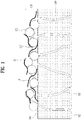
- FIG. 1 is a schematic diagram showing a portion of a separator structure according to an embodiment of the present disclosure.
- FIG. 1 shows a separator structure that may be disposed inside a secondary battery such as a lithium-ion battery.
- a structure of a separator 100 may include a porous support body 110 including a first face 111 and a second face 112, and a cellulose nano fiber 121 located on at least one of the first face 111 and the second face 112 of the support body 110.
- the support body 110 may be a porous base (fabric) having a plurality of holes 113 extending from the first face 111 to the second face 112 or may include such a porous base (fabric).
- such support body 110 may be a porous film in which one type of polyolefin (PO) (such as polyethylene (PE), polypropylene (PP), and the like)-based polymer resin exists or different types of polyolefin (PO)-based polymer resin are mixed with each other.
- PO polyolefin
- the support body 110 may include an oxide coating (not shown).
- Such support body 110 may be divided into a wet type and a dry type based on a manufacturing process.
- a wet membrane which elongates and expands pores generated when a plasticizer added in a process of forming a separator is extracted with an organic solvent, has excellent strength, elasticity and thickness, pore uniformity, and the like.
- a dry membrane which is a scheme of generating micro-cracks on a crystal interface by elongating an extruded film at a low temperature, may have a multi-layer structure including the PP/PE/PP.
- the cellulose nano fiber (CNF) 121 may be positioned on the support body 110.
- the cellulose nano fiber 121 may constitute a coating layer 120.
- the cellulose nano fiber 121 is a crystalline polymer that is a major component of a plant cell wall, and is a fiber-shaped nanomaterial having a diameter equal to or smaller than 100 nm. Such cellulose nano fiber 121 has very excellent thermal stability because the cellulose nano fiber 121 has a low coefficient of thermal expansion equal to or lower than 10 ppm/K while exhibiting high strength comparable to that of glass fiber.
- the cellulose nanofiber (CNF) 121 that has been subjected to an ionic surface treatment may be used for the structure of the separator 100.
- the ionic surface-treated cellulose nano fiber 121 may have an ionic functional group added to the cellulose nano fiber 121.
- the cellulose nano fiber 121 described in the present specification may refer to the cellulose nano fiber 121 that has been subjected to the ionic surface treatment, that is, to which the ionic functional group has been added. This will be described in detail later.
- Such an ionic functional group may impart hydrophilicity to the cellulose nano fiber 121.
- the ionic functional group may improve affinity between the cellulose nano fiber 121 and the support body 110. Accordingly, adhesion of the cellulose nano fiber 121 or the coating layer 120 containing the same may be enhanced.
- peel strength may be improved by the cellulose nano fiber 121 to which such an ionic functional group is added.
- the peel strength is also referred to as splitting resistance, and means strength of adhesive bonding. For example, this means a force acting per unit width required to separate a material bound to an object.
- the coating layer 120 containing the cellulose nano fiber 121 may have durability up to 200 °C.
- the cellulose nano fiber 121 that has been subjected to the ionic surface treatment may have a positive ion group, a negative ion group, or an amphoteric ion group.
- the positive ion group may include an amine group.
- the positive ion group may include diethylethanolamine (DEAE), epoxypropyltrimethylammonium chloride (EPTMAC), and the like.
- the negative ion group may include a carboxyl group.
- the negative ion group may include chloroacetic acid, TEMPO ((2,2,6,6-Tetramethylpiperidin-1-yl)oxyl, (2,2,6,6-tetramethylpiperidin-1-yl)oxidanyl), or the like.
- the zwitterionic group may include such a positive ion group and a negative ion group in combination. That is, the zwitterionic group may include at least one of the positive ion groups and at least one of the negative ion groups as exemplified above.
- An amount of reaction of the ionic functional group to the cellulose nano fiber 121 may be in a range from 5 to 30 %.
- the cellulose nano fiber 121 may constitute the coating layer 120 and may be attached to at least one face of the support body 110.
- the coating layer 120 may contain a binder 123. That is, the coating layer 120 may contain the binder 123 for attaching the cellulose nano fiber 121 to at least one of the first face 111 and the second face 112 of the support body 110.
- the binder 123 may be a water-based or oil-based binder.
- acrylic, PVA, PVP, PVO, SBR/CMC, and the like-based binders may be used as the water-based binder.
- Such water-based binder may have a content in a range from 0.5 to 30 wt% based on the coating layer 120.
- oil-based binder a PVDF-based binder may be used as the oil-based binder.
- oil-based binder may have a content in a range from 5 to 50 w% based on the coating layer 120.
- the cellulose nano fiber 121 may be used alone for the coating layer 120 of the support body 110.
- the coating layer 120 may contain the cellulose nano fiber 121 and the binder 123.
- Such embodiment (a fourth embodiment) will be described later.
- the cellulose nano fiber 121 when used alone for the coating layer 120, the cellulose nano fiber 121 may have a content in a range from 80 to 100 wt% (a weight ratio) based on a total weight of the coating layer 120.
- the coating layer 120 may contain inorganic particles 122 at least partially in contact with the cellulose nano fiber 121. Such inorganic particles 122 may improve the heat resistance of the entire structure of the separator 100.
- the cellulose nano fiber 121 on a fiber may form a random network structure and connect the inorganic particles 122 to each other to prevent the inorganic particles 122 from being separated.
- the inorganic particles 122 may form the network structure with particles of the cellulose nano fiber 121.
- the inorganic particles 122 may form a separate layer from the cellulose nano fiber 121.
- Such inorganic particles 122 may include at least one of Al 2 O 3 , BaTiO 3 , SiO 2 , TiO 2 , and SnO 2 .
- the inorganic particles 122 may include an inorganic powder having a permittivity equal to or higher than 5.
- crystallinity control of the cellulose nano fiber 121 may be required.
- the crystallinity of the cellulose nano fiber 121 may be in a range from 40 to 60 %.
- the coating layer 120 may be positioned on at least one face of the support body 110 to form the structure of the separator 100.
- at least one face of the support body 110 may be coated with a (dry) coating composite to form the structure of the separator 100.
- the coating layer 120 may have a thickness in a range from 0.5 to 20 ⁇ m.
- the dry coating composite may contain the cellulose nano fiber 121 to which the ionic functional group is added of the content in the range from 80 to 100 wt% (the weight ratio), the inorganic particles 122 having the permittivity equal to or higher than 5, and the binder 123.
- FIG. 2 is an SEM photograph showing a plane of a separator structure according to an embodiment of the present disclosure.
- FIG. 3 is an SEM photograph showing a cross-section of a separator structure according to an embodiment of the present disclosure.
- FIGS. 2 and 3 show SEM (Scanning Electron Microscopy) photographs in a case in which the cellulose nano fiber and the inorganic particles are coated on the support body 110.
- the cellulose nano fiber 121 and the inorganic particles 122 together constitute the coating layer 120 to be positioned on the support body 110.
- FIG. 2 shows a state in which the cellulose nano fiber 121 and the inorganic particles 122 form a network and is located on the support body 110.
- a diameter of the cellulose nano fiber 121 may be in a range from 5 to 500 nm, and a length thereof may be in a range from 500 to 10 ⁇ m. This is not shown separately, but may be identified by AFM (Atomic Force Microscopy) analysis.
- the diameter of 5 nm may correspond to a minimum diameter of the cellulose nano fiber 121.
- a thickness of the coating layer 120 may be about 1.5 ⁇ m. Therefore, when the diameter exceeds 500 nm, it may be difficult to prepare the coating layer 120.
- the inorganic particles 122 may not be able to be connected to each other, so that the adhesion of the coating layer 120 may be reduced. Therefore, an effect of improving the heat resistance according to an embodiment of the present disclosure may be reduced.
- the length of the cellulose nano fiber 121 is greater than the above numerical range, the uniformity of the coating layer 120 may be reduced.
- FIG. 4 is a schematic diagram showing an example of a cellulose nano fiber having a positive ion group of a separator structure according to an embodiment of the present disclosure.
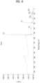
- FIGS. 5 and 6 are XPS spectra of a cellulose nano fiber shown in FIG. 4 .
- FIG. 4 a cellulose nano fiber 121 having DEAE as an example of the positive ion group is schematically shown. That is, FIG. 4 shows a state in which the DEAE is substituted on the cellulose nano fiber 121, in other words, a state in which the DEAE is given as a cationic functional group 124 to the cellulose nano fiber 121.
- the DEAE was analyzed using x-ray photoelectron spectroscopy (XPS) as shown in FIGS. 5 and 6 . That is, a nitrogen (N) functional group in the DEAE structure other than C, H, and O of the cellulose nano fiber 121 was analyzed through the XPS analysis.
- XPS x-ray photoelectron spectroscopy
- C, O, N, Cl elements are present on the cation-exchanged cellulose nano fiber 121 as a result of a survey scan of analyzing a surface 10 nm depth using the XPS in order to identify the DEAE substituted on the cellulose nano fiber 121.
- FIG. 6 shows a result of a narrow scan of the XPS. Referring to FIG. 6 , 1.8 wt% of N was detected, and a degree of cation exchange on the cellulose nano fiber 121 is able to be identified through N peak area comparison.
- cation-exchanged N (a modified N peak) on the cellulose nano fiber (121)
- binding energy is detected at a place higher than binding energy detected by a reaction reagent 2-(diethylamino)ethyl chloride hydrochloride) or impurities that did not participate in the reaction.
- FIG. 7 is a schematic diagram showing another example of a cellulose nano fiber having a positive ion group of a separator structure according to an embodiment of the present disclosure.
- FIGS. 8 and 9 are XPS spectra of a cellulose nano fiber shown in FIG. 7 .
- FIG. 7 a cellulose nano fiber 121 having EPTMAC as an example of the positive ion group is schematically shown. That is, FIG. 7 shows a state in which the EPTMAC is partially substituted on the cellulose nano fiber 121, in other words, a state in which the EPTMAC is given as a cationic functional group 125 to the cellulose nano fiber 121.
- the EPTMAC was analyzed using the x-ray photoelectron spectroscopy (XPS) as shown in FIGS. 8 and 9 . That is, a nitrogen (N) functional group in the EPTMAC functional group of the cellulose nano fiber 121 was analyzed through the XPS analysis.
- XPS x-ray photoelectron spectroscopy
- FIG. 9 shows a result of a narrow scan of the XPS. Referring to FIG. 9 , 0.7 wt% of N was detected, and a degree of partial cation exchange on the cellulose nano fiber 121 is able to be identified through N peak area comparison.
- the binding energy is detected at a higher place than binding energy detected by a reaction reagent glycidyltrimethylammonium chloride (EPTMAC) or the impurities that did not participate in the reaction.
- EPTMAC reaction reagent glycidyltrimethylammonium chloride
- FIG. 10 is a schematic diagram showing another example of a cellulose nano fiber having a negative ion group of a separator structure according to an embodiment of the present disclosure.
- FIG. 11 is an FT-IR spectrum of a cellulose nano fiber shown in FIG. 10 .
- FIG. 10 a cellulose nano fiber 121 having carboxymethyl as an example of the negative ion group is schematically shown. That is, FIG. 10 shows a state in which the carboxymethyl is partially substituted on the cellulose nano fiber 121, in other words, a state in which the carboxymethyl is given to the cellulose nano fiber 121 as an anionic functional group 126.
- energy absorption based on vibration and rotation of a molecular skeleton present in a surface functional group may be measured using infrared irradiation (FT-IR).
- FT-IR infrared irradiation
- FIG. 12 is a schematic diagram showing an example of a cellulose nano fiber having a zwitterionic group of a separator structure according to an embodiment of the present disclosure.
- a cellulose nano fiber 121 having the zwitterionic group may include both the positive ion group and the negative ion group described above.
- the cellulose nano fiber 121 may include both the amine group and the carboxyl group.
- FIG. 12 shows a state in which the amine group and the carboxyl group are partially substituted on the cellulose nano fiber 121, in other words, a state in which the DEAE and the carboxymethyl are given as the zwitterionic group 127 to the cellulose nano fiber 121.
- FIG. 13 is an XRD spectrum showing crystallinity of a cellulose nano fiber of a separator structure according to an embodiment of the present disclosure.
- crystallinity control of the cellulose nano fiber 121 may be required.
- the crystallinity of the cellulose nano fiber 121 may be approximately in a range from 20 to 80 %. That is, when the crystallinity of the cellulose nano fiber 121 is approximately in the range from 20 to 80 %, the heat resistance of the coating layer 120 may be secured.
- the crystallinity of the cellulose nano fiber 121 is equal to or higher than 40 %.
- the crystallinity of the cellulose nano fiber 121 may be in a range from 40 to 60 %.
- FIG. 13 shows the x-ray diffraction (XRD) spectrum, and as shown, a first crystalline cellulose nano fiber 121 exhibits peaks at 15 °, 17 °, 21 °, 23 °, and 34 °, and a second crystalline cellulose nano fiber 121 exhibits peaks at 12 °, 20 °, and 22 °.
- XRD x-ray diffraction
- the crystallinity of the cellulose nano fiber 121 is in the range from 40 to 60 %.
- the crystallinity of the cellulose nano fiber 121 according to an embodiment of the present disclosure may be controlled to be in the range from 40 to 60 %.
- the crystallinity may be controlled to be in a larger range, for example in a range from 20 to 80 %.
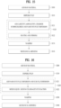
- FIG. 14 is a flowchart showing a preparation process of a cellulose nanofiber that has been subjected to ionic surface treatment of a separator structure according to an embodiment of the present disclosure.
- FIG. 14 shows a preparation process of the cellulose nano fiber 121 that has been subjected to the ionic surface treatment, which may be commonly applicable to the present disclosure.
- a raw material may be added (step S10).
- This process may be a process of adding pulp into a solvent, for example, water, and stirring the solvent.
- a solvent for example, water
- bamboo, needleleaf tree, and hardwood pulp may be used as the raw material for the pulp.
- the hardwood pulp may be used.
- the pulp may be dispersed (step S11).
- a surface area of the pulp may be improved such that the pulp may react with ions using defibration, beating, or a mixer.
- ionic surface treatment may be performed on the pulp (step S12).
- a specific process of such ionic surface treatment may differ depending on anions, cations, and zwitterions. This will be described later by way of example in detail.
- step S13 the pulp on which the ionic surface treatment has been performed may be washed.
- distilled water at a room temperature may be added, and stirred with the pulp to evenly dilute the pulp.
- the washing of the pulp may be performed using a strainer. This process may proceed until pH of the solution becomes neutral.
- a mechanical grinding process may be performed (step S14).
- aqueous counter collision, a high-speed defibrating machine, a grinder, a high pressure homogenizer, a high pressure impingement mill, a ball mill, a bead mill, a disk type refiner, a conical refiner, a twin-screw kneader, a vibration mill, a homomixer under a under high speed rotation, an ultrasonic disperser, a beater, and the like may be used.
- FIG. 15 is a flowchart showing a preparation process of a cation-treated cellulose nano fiber of a separator structure according to an embodiment of the present disclosure.
- a raw material may be added (step S100).
- the pulp may be dispersed (step S110).
- a pulp dispersion concentration is in a range from 0.2 to 15 wt%.
- step S120 the cationic surface treatment may be performed on the pulp (step S120).
- 2-(diethylamino)ethyl chloride hydrochloride and sodium hydroxide (NaOH) may be added into the pulp dispersion (S121).
- a mixing ratio of 2-(diethylamino)ethyl chloride hydrochloride in the pulp dispersion may be in a range from a 1:1 weight ratio (wt%) to a 1:20 weight ratio. It may be advantageous that the mixing ratio of the pulp and NaOH is in a range from a 1:1 weight ratio to a 1:15 weight ratio.
- pulp dispersion may be heated and stirred (step S122).
- step S130 the pulp on which the cationic surface treatment has been performed may be washed.
- step S140 a mechanical grinding process
- FIG. 16 is a flowchart showing a preparation process of an anion-treated cellulose nano fiber of a separator structure according to an embodiment of the present disclosure.
- a raw material may be added (step S200).
- the pulp may be dispersed (step S210).
- the pulp dispersion concentration is in a range from 0.2 to 15 wt%.
- the anionic surface treatment may be performed on the pulp (step S220).
- sodium hydroxide NaOH
- NaOH sodium hydroxide
- a mixing ratio of the pulp and NaOH may be in a range from 0.1 weight ratio (wt%) to 0.5 weight ratio.
- pulp dispersion may be reacted with sodium chloroacetate (step S222).
- a mixing ratio of the pulp and the sodium chloroacetate is in a range from 0.1 to 0.7 wt%.
- pulp on which the cationic surface treatment has been performed may be washed (step S230).
- step S240 a mechanical grinding process may be performed (step S240).
- FIG. 17 is a flowchart showing a preparation process of a cellulose nano fiber treated with a zwitterion of a separator structure according to an embodiment of the present disclosure.
- the cationic surface treatment and the anionic surface treatment described above may be sequentially performed.
- the cationic surface treatment may be performed using the DEAE, and then, as an example of the anionic surface treatment, the anionic surface treatment may be performed using the carboxymethyl by adjusting the concentration.
- steps S300 to S330 may be the same as the cationic surface treatment process described above, that is, steps S100 to S130.
- steps S350 to S380 may be the same as the anionic surface treatment process described above, that is, steps S200 to S240.
- a process (step S340) of adjusting the concentration may be performed.
- Such process of adjusting the concentration may include a process of introducing or removing an appropriate solvent.
- a duplicated description will be omitted.
- FIG. 18 is a flowchart showing a preparation process of a coating solution composite of a separator structure according to an embodiment of the present disclosure.
- the structure of the separator 100 may include the coating layer 120 containing the cellulose nano fiber 121 that has been subjected to the ionic surface treatment on at least one face of the support body 110.
- the coating layer 120 containing the cellulose nano fiber 121 that has been subjected to the ionic surface treatment may be formed through coating with a coating solution on at least one face of the support body 110.
- the structure of the separator 100 according to an embodiment of the present disclosure may be formed through a step of obtaining the coating solution composite and a step of coating the coating solution composite on the support body 110.
- Such a coating solution composite may contain 0.1 to 2 wt% of the nano cellulose to which the ionic functional group is given, the inorganic particles having the permittivity constant equal to or higher than 5, and the binder.
- the concentration may be adjusted by adding or removing a dispersion solvent to or from the cellulose nano fiber (CNF) 121 (step S400).
- the concentration may be controlled by adding water or through a dehydration process using microwave equipment.
- the concentration of the cellulose nano fiber 121 may be in a range from 0.1 to 2 wt% relative to the dispersion solvent.
- a solvent may be added to the water-based dispersion mixture of the cellulose nano fiber 121 (step S410).
- the solvent may be composed of an organic solvent and deionized water mixed with each other or the organic solvent alone.
- acetone, ethanol, IPA, and the like having a boiling point equal to or lower than 100 °C may be used.
- a content of the organic solvent added may be in a range from 10 to 80 % relative to the deionized water in the case of the water-based coating solution.
- the content of the organic solvent added may be in a range from 90 to 100 %.
- the inorganic particles 122 may be further added to the dispersion into which the solvent is added (step S410).
- the inorganic particles may include at least one of Al 2 O 3 , BaTiO 3 , SiO 2 , TiO 2 , and SnO 2 , and inorganic powder having a permittivity constant equal to or higher than 5 may be additionally used.
- a particle size of the inorganic particle 122 may be in a range from 50 nm to 1 ⁇ m based on D50.
- a particle shape of the inorganic particles 122 may be spherical, planar, acicular, hexahedral, polyhedral, amorphous, and the like.
- a mixing and dispersing process (step S420) may be performed.
- a ball-milling process may be performed to uniformly mix the dispersion (slurry) with the inorganic particles 122 and crush the inorganic particles 122.
- the binder 123 may be added (step S430).
- the binder 123 may bind the cellulose nano fiber 121 with the inorganic particles 122, or increase adhesion of the coating solution to the support body 110.
- Acrylic, PVA, PVP, PVO, SBR/CMC, and the like-based binders may be used as a binder for water-based coating solution.
- a content of the binder for such water-based coating solution may be in a range from 0.5 to 30 %.
- oil-based coating solution binder PVDF and the like-based binders may be used.
- a content of such oil-based coating solution binder may be in a range from 5 to 50 %.
- the mixed solution may be stirred to prepare the coating solution composite (step S440).
- the coating solution composite (slurry) for coating the support body 110 may be prepared by uniformly mixing the mixed solution with the binder by planetary mixing.
- the separator 100 may be prepared by coating such a coating solution composite on the support body 110. When the coating solution is dried, a dry coating layer 120 may be formed. Such dry coating layer 120 may contain 1 to 10 wt% of the cellulose nano fiber 121 to which the ionic functional group is given.
- the dry coating composite may contain 1 to 10 wt% of the cellulose nano fiber 121 to which the ionic functional group is given, the inorganic particles having the permittivity constant equal to or higher than 5, and the binder.
- FIG. 19 is a schematic cross-sectional view showing a separator structure according to a first embodiment of the present disclosure.
- FIG. 20 is a flowchart showing a process of preparing a separator structure according to a first embodiment of the present disclosure.
- FIG. 19 shows a structure of the separator 100 in which the coating layers 120 containing the cellulose nano fiber 121 to which the ionic functional group is given and the inorganic particles 122 are respectively coated on the both faces of the support body 110.
- the support body 110 may be a porous base (fabric) having the plurality of holes 113 extending from one face to the opposite face or may include such a porous base (fabric).
- such support body 110 may be a porous film in which one type of polyolefin (such as PE, PP, and the like)-based polymer resin exists or different types of polyolefin-based polymer resin are mixed with each other.
- one type of polyolefin such as PE, PP, and the like
- the cellulose nano fiber (CNF) 121 and the inorganic particles 122 may constitute the coating layer 120.
- the cellulose nanofiber (CNF) 121 that has been subjected to the ionic surface treatment may be used for such structure of the separator 100.
- Such cellulose nanofiber 121 that has been subjected to the ionic surface treatment may be the cellulose nano fiber 121 to which the ionic functional group is given.
- FIG. 19 Such structure of the separator 100 shown in FIG. 19 may be substantially the same as the structure of the separator 100 shown in FIG. 1.
- FIG. 1 shows the state in which the coating layer 120 is located only on the first face 111 of the support body 110, but other than that, FIG. 1 may be substantially the same as the embodiment of FIG. 19 . That is, the coating layer 120 shown in FIG. 19 may also contain the binder 123 in addition to the cellulose nano fiber 121 and the inorganic particles 122. In other words, the illustration of the binder 123 is omitted in FIG. 19 .
- the cellulose nano fiber 121 and the inorganic particles 122 form the network structure.
- the matters described with reference to FIG. 1 may be equally applied to the present embodiment. Therefore, a duplicated description will be omitted.
- the process of preparing the structure of the separator 100 shown in FIG. 19 will be described with reference to FIG. 20 .
- the process of preparing the structure of the separator 100 may be substantially the same as the process of coating the coating solution composite on the support body 110 described above.
- the concentration may be adjusted by adding or removing the dispersion solvent to or from the cellulose nano fiber (CNF) 121 (step S500).
- the solvent may be added into the water-based dispersion mixture of the cellulose nano fiber 121 (step S510).
- the inorganic particle 122 may be further added into the dispersion into which the solvent is added (step S510).
- the inorganic particles may include at least one of Al 2 O 3 , BaTiO 3 , SiO 2 , TiO 2 , and SnO 2 .
- the inorganic powders with the permittivity constant equal to or higher than 5 may be used.
- step S520 the mixing and dispersing process
- the ball-milling process may be performed to uniformly mix the dispersion (slurry) with the inorganic particles 122 and crush the inorganic particles 122.
- the binder 123 may be added (step S530).
- the binder 123 may bind the cellulose nano fiber 121 with the inorganic particles 122, or increase the adhesion of the coating solution to the support body 110.
- the mixture solution may be stirred to prepare the coating solution composite (step S540).
- coating solution composite may be coated on the support body 110 (the fabric or the base) to prepare the separator 100.
- a porous polyolefin-based fabric may be used as the support body 110 (the fabric or the base).
- dip coating, bar coating, die coating, comma coating, gravure coating, or a mixture scheme thereof may be used to coat the coating solution composite on at least one face, that is, one face or both faces of the support body 110.
- FIG. 21 is a schematic cross-sectional view showing a separator structure according to a second embodiment of the present disclosure.
- FIG. 22 is a flowchart showing a process of preparing a separator structure according to a second embodiment of the present disclosure.
- FIG. 21 shows a structure of a separator 100a in which coating layers 120a containing the cellulose nano fiber 121 to which the ionic functional group is given and the inorganic particles 122 are respectively coated on the both faces of the support body 110.
- the coating layer 120a may include a layer of the cellulose nano fiber 121 located closer to the support body 110, and a layer of the inorganic particles 122 located on the layer of the cellulose nano fiber 121.
- the structure of the separator 100a according to the second embodiment may contain the layer of the cellulose nano fiber 121 and the layer of the inorganic particles 122 that are positioned to be distinguished from each other.
- such cellulose nano fiber 121 and inorganic particles 122 have very small sizes, so that the cellulose nano fiber 121 and the inorganic particles 122 may be located in a mixed state in at least a portion of the coating layer 120a.
- Such structure of the separator 100a according to the second embodiment may be formed through two coating processes.
- the coating process may include a first coating process of coating the layer of cellulose nano fiber 121 on the support body 110, and a second coating process of coating the layer of the inorganic particles 122 on the layer of the cellulose nano fiber 121.
- the concentration may be adjusted by adding or removing the dispersion solvent to or from the cellulose nano fiber (CNF) 121 (step S600).
- the concentration may be controlled by adding the water or through the dehydration process using the microwave equipment.
- the concentration of the cellulose nano fiber 121 may be in the range from 0.1 to 2 wt% relative to the dispersion solvent.
- the organic solvent may be added into the water-based dispersion mixture of the cellulose nano fiber 121 (step S610).
- the solvent may be composed of the organic solvent and the deionized water mixed with each other or the organic solvent alone.
- the organic solvent the acetone, the ethanol, the IPA, and the like having the boiling point equal to or lower than 100 °C may be used.
- the content of the organic solvent added may be in the range from 10 to 80 % relative to the deionized water in the case of the water-based coating solution.
- the first coating process may be performed by coating the dispersion of the cellulose nano fiber 121 to which the organic solvent is added to the support body 110 (the fabric or the base) (step S620).
- the dip coating, the bar coating, the die coating, the comma coating, the gravure coating, or the mixture scheme thereof may be used to coat the coating solution composite on at least one face, that is, one face or both faces of the support body 110.
- the second coating may be performed.
- the inorganic particles 122 may be added and dispersed in the solvent (step S630).
- the solvent may be composed of the organic solvent and the deionized water mixed with each other or the organic solvent alone.
- the organic solvent the acetone, the ethanol, the IPA, and the like having the boiling point equal to or lower than 100 °C may be used.
- the content of the organic solvent added may be in the range from 10 to 80 % relative to the deionized water in the case of the water-based coating solution.
- the inorganic particles may include at least one of Al2O3, BaTiO3, SiO2, TiO2, and SnO2.
- the inorganic powders with the permittivity constant equal to or higher than 5 may be used.
- the particle size of the inorganic particle 122 may be in the range from 50 nm to 1 ⁇ m based on D50.
- the particle shape of the inorganic particles 122 may be spherical, planar, acicular, hexahedral, polyhedral, amorphous, and the like.
- the ball-milling process may be performed to uniformly mix the dispersion (slurry) with the inorganic particles 122 and crush the inorganic particles 122.
- the binder 123 may be added (step S640).
- the binder for the water-based coating solution the acrylic, PVA, PVP, PVO, SBR/CMC, and the like-based binders may be used.
- a content of such binder for the water-based coating solution may be in a range from 0.5 to 30 wt%.
- the oil-based coating solution binder may use the PVDF and the like-based binder.
- the content of such oil-based coating solution binder may be in the range from 5 to 50 %.
- the mixture may be stirred to prepare the coating solution composite containing the inorganic particles 122 (step S650).
- coating solution composite may be coated on the layer of the cellulose nano fiber (CNF) 121 to prepare the separator 100 (step S660).
- the dip coating, the bar coating, the die coating, the comma coating, the gravure coating, or the mixture scheme thereof may be used.
- FIG. 23 is a schematic cross-sectional view showing a separator structure according to a third embodiment of the present disclosure.
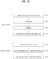
- FIG. 24 is a flowchart showing a process of preparing a separator structure according to a third embodiment of the present disclosure.
- FIG. 23 shows a structure of a separator 100b in which coating layers 120b containing the cellulose nano fiber 121 to which the ionic functional group is given and the inorganic particles 122 are respectively coated on the both faces of the support body 110.
- the coating layer 120b may include a layer of the inorganic particles 122 located closer to the support body 110, and a layer of the cellulose nano fiber 121 located on the layer of the inorganic particles 122.
- the structure of the separator 100a according to the third embodiment may include the layer of the cellulose nano fiber 121 and the layer of the inorganic particles 122 that are positioned to be distinguished from each other.
- such cellulose nano fiber 121 and inorganic particles 122 have very small sizes, so that the cellulose nano fiber 121 and the inorganic particles 122 may be located in a mixed state in at least a portion of the coating layer 120b.
- Such structure of the separator 100b according to the third embodiment may be formed through two coating processes.
- the coating process may include a first coating process of coating the layer of the inorganic particles 122 on the support body 110, and a second coating process of coating the layer of the cellulose nano fiber 121 on the layer of the inorganic particles 122.
- Such preparation process may be substantially the same as a process in which an order of the first coating and the second coating described with reference to FIG. 22 is different. Therefore, a duplicated description will be simply made or omitted.
- the inorganic particles 122 may be added and dispersed in the solvent (step S700).
- the solvent may be composed of the organic solvent and the deionized water mixed with each other or the organic solvent alone.
- the organic solvent the acetone, the ethanol, the IPA, and the like having the boiling point equal to or lower than 100 °C may be used.
- the content of the organic solvent added may be in the range from 10 to 80 % relative to the deionized water in the case of the water-based coating solution.
- the inorganic particles may include at least one of Al 2 O 3 , BaTiO 3 , SiO 2 , TiO 2 , and SnO 2 .
- the inorganic powders with the permittivity constant equal to or higher than 5 may be used.
- the binder 123 may be added (step S710).
- the binder for the water-based coating solution the acrylic, PVA, PVP, PVO, SBR/CMC, and the like-based binders may be used.
- the content of such binder for the water-based coating solution may be in the range from 0.5 to 30 wt%.
- the PVDF and the like-based may be used as the oil-based coating solution binder.
- the content of such oil-based coating solution binder may be in the range from 5 to 50 %.
- step S720 the mixture may be stirred to prepare the coating solution composite containing the inorganic particles 122 (step S720).
- the first coating process may be performed by coating such coating solution composite on the support body 110 (the fabric or the base) (step 5730).
- dip coating, bar coating, die coating, comma coating, gravure coating, or a mixture scheme thereof may be used to coat the coating solution composite on at least one face, that is, one face or both faces of the support body 110.
- the second coating may be performed.
- the concentration may be adjusted by adding or removing the dispersion solvent to or from the cellulose nano fiber (CNF) 121 (step S740).
- the concentration may be controlled by adding the water or through the dehydration process using the microwave equipment.
- the concentration of the cellulose nano fiber 121 may be in the range from 0.1 to 2 wt% relative to the dispersion solvent.
- the organic solvent may be added into the water-based dispersion mixture of the cellulose nano fiber 121 and dispersed (step S750).
- the solvent may be composed of the organic solvent and the deionized water mixed with each other or the organic solvent alone.
- the organic solvent the acetone, the ethanol, the IPA, and the like having the boiling point equal to or lower than 100 °C may be used.
- the content of the organic solvent added may be in the range from 10 to 80 % relative to the deionized water in the case of the water-based coating solution.
- the second coating process may be performed by coating the dispersion of the cellulose nano fiber 121 into which the organic solvent is added on the first coating layer (the layer of the organic particles 122) (step S760).
- the dip coating, the bar coating, the die coating, the comma coating, the gravure coating, or the mixture scheme thereof may be used.
- FIG. 25 is a schematic cross-sectional view showing a separator structure according to a fourth embodiment of the present disclosure.
- FIG. 26 is a flowchart showing a process of preparing a separator structure according to a fourth embodiment of the present disclosure.
- FIG. 25 shows a structure of a separator 100c in which coating layers 120c containing the cellulose nano fiber 121 to which the ionic functional group is given are respectively coated on both faces of the support body 110.
- the coating layer 120c may include a layer of the cellulose nano fiber 121.
- the present embodiment shows an embodiment in which the coating layer 120c does not contain the inorganic particles 122.
- the coating layer 120c that does not contain the inorganic particles 122 but contains the cellulose nano fiber 121.
- a content of such coating layer 120c not containing the inorganic particles 122 but containing the cellulose nano fiber 121 may be in a range from 80 to 100 wt%.
- a large amount of cellulose nano fiber 121 may be used, so that an effect resulted from characteristics of the cellulose nano fiber 121 may be increased.
- the concentration may be adjusted by adding or removing the dispersion solvent to or from the cellulose nano fiber (CNF) 121 (step S800).
- the concentration may be controlled by adding the water or through the dehydration process using the microwave equipment.
- the organic solvent may be added into the water-based dispersion mixture of the cellulose nano fiber 121 and dispersed (step S810).
- the solvent may be composed of the organic solvent and the deionized water mixed with each other or the organic solvent alone.
- the organic solvent the acetone, the ethanol, the IPA, and the like having the boiling point equal to or lower than 100 °C may be used.
- the content of the organic solvent added may be in the range from 10 to 80 % relative to the deionized water in the case of the water-based coating solution.
- the coating process may be performed by coating the dispersion of the cellulose nano fiber 121 to which the organic solvent is added on the support body 110 (the fabric or the base) (step S820).
- dip coating, bar coating, die coating, comma coating, gravure coating, or a mixture scheme thereof may be used to coat the coating solution composite on at least one face, that is, one face or both faces of the support body 110.
- the solvent may be dried. Therefore, the dry coating composite may contain 80 to 100 wt% of the cellulose nano fiber 121.
- an organic-inorganic composite separator having excellent heat resistance and mechanical strength may be prepared simply by preparing the coating solution composite (the water-based or oil-based coating solution) mixed with the polymer binder 123 to strengthen the adhesion of the ion-treated cellulose nano fiber 121, and coating the coating solution composite on one face or both faces of the polyolefin-based support body 110 and drying the coating solution composite.
- the coating solution composite the water-based or oil-based coating solution
- the inorganic particles 122 may be added and coated for additional performance improvement.
- a film of a random network structure of the cellulose nano fiber 121 on a fiber may connect the inorganic particles 122 with each other to prevent the inorganic particles 122 from being eliminated.
- performances such as thermal contraction characteristics, mechanical strength, and the like may be ameliorated.
- the structure of the separator 100 may be implemented in a form in which the embodiments are combined with each other depending on a purpose of use.
- a form in which the structures of the first and second embodiments are combined with each other a form in which the structures of the first and third embodiments are combined with each other, a form in which the structures of the second and third embodiments are combined with each other, and a form in which the structures of the first to third embodiments are combined with each other may also be possible.
- the cellulose nano fiber 121 and the inorganic particles 122 may be coupled to each other in various forms in addition to the above-described embodiments to constitute the separator structure.
- a closing function which is one of main performances of the secondary battery separator, may also be maintained.
- the closing function refers to a function of blocking a risk of battery explosion or the like resulted from closing of the porous structure of the support body 110 when the temperature exceeds a limit temperature.
- the high temperature durability may be improved by the application of the cellulose nano fiber 121 to which the ionic functional group is given, thereby maximizing battery use safety.
- FIG. 27 is a graph showing a thermal contraction percentage of a separator structure according to an embodiment of the present disclosure.
- FIG. 28 is a graph showing an air permeability of a separator structure according to an embodiment of the present disclosure.
- FIG. 29 is a graph showing a peel strength of a separator structure according to an embodiment of the present disclosure.
- Data shown in FIGS. 27 to 29 is based on the structure of the separator 100 according to the first embodiment.
- the data shown in FIGS. 27 to 29 represent each of characteristics based on the content of the cellulose nano fiber 121.
- Table 1 shows each of the characteristics based on the content of the cellulose nano fiber 121 as a table.
- CNF content wt.% Thermal contraction percentage (%) Air permeability (s/ 100cc) Peel strength (g ⁇ f) Impregnation property (mm) 0 54.4 35 127.7 2.4 2 10.0 50 191.3 2.2 3 7.5 65 208.8 1.8 4 3.8 92.6 272.3 -
- the characteristics that is, a thermal contraction percentage, an air permeability, a peel strength, and an impregnation property were respectively measured based on following criteria.
- Thermal contraction percentage a degree of shrinkage of the film after being left at 150 degrees for 30 minutes.
- Air permeability Measures a time it takes for 100 cc of air to pass through the separator.
- Impregnation property After filling a 10 ⁇ l syringe with 2 ⁇ l, which is a fixed quantity, of polycarbonate (PC), drop polycarbonate (PC) on the separator and then measure a distance of diffusion outward of the droplet 5 minutes later.
- PC polycarbonate
- the high temperature thermal contraction percentage and the mechanical strength, which are important characteristics of the secondary battery may be remarkably ameliorated.
- FIG. 30 is a graph showing thermal contraction percentages of separator structures according to first and fourth embodiments of the present disclosure.
- Table 2 shows the thermal contraction percentages of the separator structures according to the first and fourth embodiments in a table.
- the thermal contraction percentage reaches 54.5 %.
- the thermal contraction percentage is significantly reduced to 4 or 5 %.
- the thermal contraction percentage is greatly reduced to 5 %. Therefore, the high temperature durability may be secured even when the cellulose nano fiber 121 is used alone.
- all preparation processes are performed in the aqueous solution and are harmless to an environment.
- all ion treatment and nano-ization processes may be performed in an aqueous solution at a low temperature in a range from a room temperature to about 80 °C.
- such low temperature process has an advantage of short preparation time.
- the adhesion between the support body 110 containing a hydrophobic fabric and the coating layer 120 may be secured by surface charges of the ion-treated cellulose nano fiber.
- the mechanical performance such as the peel strength may be secured without additional complex hydrophobic surface treatment.
- the structure in which the coating layer 120 containing the cellulose nano fiber 121, the inorganic particles 122, and the polymer binder 123 is formed on the porous polyolefin-based support body 110 may secure uniform pore distribution of the support body 110 through composition control of the coating layer 120. Therefore, the closing function of the separator 100 may be implemented, and continuous processes are possible in terms of a preparation process, thereby having an advantage of excellent productivity.
- FIG. 31 is a schematic cross-sectional view showing a secondary battery including a separator structure according to an embodiment of the present disclosure.
- Such secondary battery 400 may include a positive electrode 200, a negative electrode 300, a separator 100 positioned between the positive electrode 200 and the negative electrode 300, and electrolytes 10 respectively positioned between the positive electrode 200 and the separator 100 and between the negative electrode 300 and separator 100.
- the electrolyte 10 may include a liquid electrolyte or a solid electrolyte.
- the separator 100 may include the porous support body 110 including the first face and the second face, and the cellulose nano fiber 121 that has been subjected to the ion surface treatment located on at least one of the first and second faces of the support body 110.
- the separator 100 may contain the inorganic particles 122 and the binder having at least one face connected to the cellulose nano fiber 121.
- the secondary battery 400 is composed of the electrodes 200 and 300, the separator 100, and the electrolytes 10.
- the components may be stacked in an order of the positive electrode 200, the separator 100, and the negative electrode 300 by a cell capacity.
- the secondary battery may be manufactured in a pouch or cylindrical shape depending on a cell shape, and may be manufactured through electrolyte injection after cell assembly.
- the positive electrode 200 may be made of aluminum and the negative electrode 300 may be made of copper.
- the positive electrode 200 may be prepared by applying an active material slurry to the aluminum
- the negative electrode 300 may be prepared by applying the active material slurry to a copper foil metal current collector plate.
- positive electrode active material slurry may be prepared by mixing a powder type active material, a PVDF binder, and a conductive material with an NMP solvent.
- the binder and the NMP solvent are used for negative active material slurry.
- the negative active material slurry may be prepared with the water-based binder, a surfactant, and the water as a solvent.
- An electrolyte may be composed of a lithium salt, a solvent, and an additive.
- a lithium salt LiPF 6 , LiBF 4 , LiAsF 6 , LiClO 4 , LiCF 3 SO 3 , and the like may be used.
- the solvent ethylene carbonate (EC), propylene carbonate (PC), dimethyl carbonate (DCM), dimethyl carbonate (DEC), ethylmethyl carbonate (ECM), and the like may be used alone or in combination.
- Such a secondary battery may have the technical effects described above. That is, the high temperature durability of the secondary battery may be ensured, and the mechanical strength thereof may be improved.
- a separator structure for the secondary battery a method for preparing the same, and the secondary battery using the same.
Landscapes
- Chemical & Material Sciences (AREA)
- Chemical Kinetics & Catalysis (AREA)
- General Chemical & Material Sciences (AREA)
- Electrochemistry (AREA)
- Engineering & Computer Science (AREA)
- Inorganic Chemistry (AREA)
- Manufacturing & Machinery (AREA)
- Wood Science & Technology (AREA)
- Life Sciences & Earth Sciences (AREA)
- Materials Engineering (AREA)
- Organic Chemistry (AREA)
- Composite Materials (AREA)
- Cell Separators (AREA)
Applications Claiming Priority (4)
| Application Number | Priority Date | Filing Date | Title |
|---|---|---|---|
| KR20200058406 | 2020-05-15 | ||
| KR20200058386 | 2020-05-15 | ||
| KR1020210036209A KR102352401B1 (ko) | 2020-05-15 | 2021-03-19 | 분리막 구조, 그 제조 방법 및 이를 이용한 이차전지 |
| PCT/KR2021/005884 WO2021230622A1 (fr) | 2020-05-15 | 2021-05-11 | Structure de séparateur, son procédé de fabrication et batterie secondaire utilisant celle-ci |
Publications (2)
| Publication Number | Publication Date |
|---|---|
| EP4152506A1 true EP4152506A1 (fr) | 2023-03-22 |
| EP4152506A4 EP4152506A4 (fr) | 2025-05-14 |
Family
ID=75469526
Family Applications (1)
| Application Number | Title | Priority Date | Filing Date |
|---|---|---|---|
| EP21805248.8A Pending EP4152506A4 (fr) | 2020-05-15 | 2021-05-11 | Structure de séparateur, son procédé de fabrication et batterie secondaire utilisant celle-ci |
Country Status (5)
| Country | Link |
|---|---|
| US (1) | US11978922B2 (fr) |
| EP (1) | EP4152506A4 (fr) |
| KR (1) | KR102352401B1 (fr) |
| CN (1) | CN115668621A (fr) |
| WO (1) | WO2021230622A1 (fr) |
Families Citing this family (15)
| Publication number | Priority date | Publication date | Assignee | Title |
|---|---|---|---|---|
| US11811088B2 (en) * | 2019-09-19 | 2023-11-07 | Kabushiki Kaisha Toshiba | Separator, electrode group, secondary battery, battery pack, vehicle, and stationary power supply |
| KR102352401B1 (ko) | 2020-05-15 | 2022-01-19 | 엘지전자 주식회사 | 분리막 구조, 그 제조 방법 및 이를 이용한 이차전지 |
| KR102617166B1 (ko) | 2021-12-21 | 2023-12-21 | 주식회사 엘지에너지솔루션 | 전기화학소자용 분리막 및 이를 포함하는 전기화학소자 |
| EP4369504A4 (fr) * | 2022-02-18 | 2025-07-02 | Lg Energy Solution Ltd | Séparateur céramique composite poreuse, dispositif électrochimique le comprenant et procédé de préparation du séparateur céramique composite poreuse |
| EP4329078A4 (fr) * | 2022-02-21 | 2025-07-09 | Shenzhen Senior Technology Material Co Ltd | Batterie, séparateur de batterie et procédé de préparation de séparateur |
| CN115148965B (zh) * | 2022-05-18 | 2024-11-01 | 湖南大学 | 一种3d打印高负载锌离子电池电极及其制备方法 |
| CN116982209A (zh) * | 2022-06-24 | 2023-10-31 | 宁德时代新能源科技股份有限公司 | 隔离膜、其制备方法及其相关的二次电池和用电装置 |
| CN116897461B (zh) * | 2022-06-24 | 2024-09-06 | 宁德时代新能源科技股份有限公司 | 隔离膜、其制备方法及其相关的二次电池和用电装置 |
| EP4542754A4 (fr) * | 2022-06-24 | 2025-12-24 | Contemporary Amperex Technology Hong Kong Ltd | Séparateur, son procédé de préparation, et batterie secondaire et appareil électrique s'y rapportant |
| KR20250007597A (ko) * | 2022-06-24 | 2025-01-14 | 컨템포러리 엠퍼렉스 테크놀로지 (홍콩) 리미티드 | 세퍼레이터, 그 제조 방법 및 그 관련 이차 전지와 전력 소비 장치 |
| WO2024036820A1 (fr) * | 2022-08-15 | 2024-02-22 | 宁德时代新能源科技股份有限公司 | Séparateur, son procédé de préparation et batterie secondaire associée à celui-ci, et dispositif électrique |
| CN120300404A (zh) * | 2022-08-15 | 2025-07-11 | 宁德时代新能源科技股份有限公司 | 隔离膜、其制备方法及其相关的二次电池和用电装置 |
| CN119330381B (zh) * | 2022-12-05 | 2026-01-27 | 宁德时代新能源科技股份有限公司 | 氧化铝颗粒、其制备方法及隔离膜、电池和用电装置 |
| EP4528900A4 (fr) * | 2023-08-14 | 2026-03-11 | Shanghai Energy New Mat Tech Co Ltd | Séparateur composite et son procédé de préparation, et batterie |
| CN119905684A (zh) * | 2023-10-26 | 2025-04-29 | 中国科学院大连化学物理研究所 | 一种用于水系锌离子电池的膜及其制备方法和应用 |
Family Cites Families (10)
| Publication number | Priority date | Publication date | Assignee | Title |
|---|---|---|---|---|
| EP2286481A1 (fr) * | 2008-04-28 | 2011-02-23 | Philippe Saint Ger AG | Dispositif de production de courant |
| KR101491059B1 (ko) | 2011-03-25 | 2015-02-10 | 주식회사 엘지화학 | 세퍼레이터 및 그 세퍼레이터의 제조방법 |
| JP2014175232A (ja) * | 2013-03-12 | 2014-09-22 | Mitsubishi Paper Mills Ltd | 電池用セパレータ |
| JP2014232845A (ja) * | 2013-05-30 | 2014-12-11 | 太陽誘電株式会社 | 電気化学デバイス及びそれに用いるセパレータ |
| KR20160043768A (ko) * | 2014-10-14 | 2016-04-22 | 울산과학기술원 | 유무기 복합 분리막, 그의 제조방법 및 이를 포함한 전기 화학 소자 |
| JP6733487B2 (ja) * | 2016-10-11 | 2020-07-29 | ヤマハ株式会社 | 音響解析方法および音響解析装置 |
| JP6942952B2 (ja) | 2016-10-14 | 2021-09-29 | 王子ホールディングス株式会社 | 電池用セパレータ、電池及び電池用セパレータ塗液 |
| JP6870317B2 (ja) * | 2016-12-26 | 2021-05-12 | 王子ホールディングス株式会社 | 電池用セパレータ塗液、電池用セパレータ及び電池 |
| KR102598712B1 (ko) * | 2018-02-01 | 2023-11-06 | 삼성전자주식회사 | 다공성막, 이를 포함하는 세퍼레이터, 이를 포함하는 전기화학 소자, 및 다공성막 제조방법 |
| KR102352401B1 (ko) * | 2020-05-15 | 2022-01-19 | 엘지전자 주식회사 | 분리막 구조, 그 제조 방법 및 이를 이용한 이차전지 |
-
2021
- 2021-03-19 KR KR1020210036209A patent/KR102352401B1/ko active Active
- 2021-05-11 WO PCT/KR2021/005884 patent/WO2021230622A1/fr not_active Ceased
- 2021-05-11 CN CN202180035632.XA patent/CN115668621A/zh active Pending
- 2021-05-11 EP EP21805248.8A patent/EP4152506A4/fr active Pending
- 2021-05-13 US US17/319,930 patent/US11978922B2/en active Active
Also Published As
| Publication number | Publication date |
|---|---|
| KR102352401B1 (ko) | 2022-01-19 |
| US11978922B2 (en) | 2024-05-07 |
| CN115668621A (zh) | 2023-01-31 |
| EP4152506A4 (fr) | 2025-05-14 |
| KR20210038490A (ko) | 2021-04-07 |
| US20210359375A1 (en) | 2021-11-18 |
| WO2021230622A1 (fr) | 2021-11-18 |
Similar Documents
| Publication | Publication Date | Title |
|---|---|---|
| US11978922B2 (en) | Separator structure for secondary battery, method for making the separator, and the secondary battery using the same | |
| EP2706591B1 (fr) | Séparateur comprenant une couche de revêtement poreuse et dispositif électrochimique comprenant celui-ci | |
| EP2808923B1 (fr) | Procédé de fabrication de séparateur, séparateur fabriqué ainsi et dispositif électrochimique le comprenant | |
| EP1782489B1 (fr) | Nouveau separateur poreux composite organique/inorganique et dispositif electrochimique le contenant. | |
| US9972816B2 (en) | Slurry for forming insulating layer, separator for electrochemical device, method for producing the same, and electrochemical device | |
| EP2634836B1 (fr) | Séparateur comprenant une couche de revêtement d'un mélange inorganique et organique et batterie comprenant celui-ci | |
| US9070930B2 (en) | Organic/inorganic composite electrolyte and electrochemical device prepared thereby | |
| KR102249890B1 (ko) | 이차 전지용 분리막, 이차 전지용 분리막의 제조 방법 및 이를 포함하는 리튬 이차 전지 | |
| KR102812315B1 (ko) | 분리막 및 이를 포함하는 리튬 이차 전지 | |
| KR20170007210A (ko) | 세퍼레이터 및 이를 포함하는 전기화학소자 | |
| EP1972017A1 (fr) | Separateur composite organique/inorganique presentant un gradient morphologique, procede de fabrication correspondant et dispositif electrochimique contenant un tel separateur | |
| KR20200070316A (ko) | 다층 나노다공성 세퍼레이터 | |
| CN116250146B (zh) | 用于锂二次电池的隔板、制造其的方法、和包括其的锂二次电池 | |
| JP7359937B2 (ja) | 改善された電極接着力及び抵抗特性を有するリチウム二次電池用分離膜及び該分離膜を含むリチウム二次電池 | |
| KR20130088901A (ko) | 미다공막 및 그 제조 방법 | |
| KR102229625B1 (ko) | 이차 전지용 분리막 및 이를 포함하는 리튬 이차 전지 | |
| EP3671899B1 (fr) | Procédé de fabrication de séparateur, séparateur ainsi formé, et dispositif électrochimique le comprenant | |
| KR20220041774A (ko) | 리튬 이차 전지용 분리막 및 이의 제조방법 | |
| KR20240061676A (ko) | 이차전지용 분리막, 이의 제조방법 및 이를 포함하는 이차전지 | |
| KR20130091779A (ko) | 미다공막 및 그 제조 방법 | |
| KR20240001615A (ko) | 분리막 코팅용 슬러리 조성물, 이를 이용한 분리막, 및 이를 포함하는 전기화학소자 | |
| KR102771007B1 (ko) | 리튬 이차 전지용 분리막 및 이의 제조방법 및 이에 의해 제조된 분리막 | |
| KR102413378B1 (ko) | 세퍼레이터의 제조 방법, 이로부터 제조된 세퍼레이터 및 이를 포함하는 전기화학소자 | |
| JP7152945B2 (ja) | リチウムイオン二次電池の負極活物質用ナノ粒子集合体の製造方法 | |
| EP4386964A1 (fr) | Séparateur pour batterie au lithium rechargeable et batterie au lithium rechargeable le comprenant |
Legal Events
| Date | Code | Title | Description |
|---|---|---|---|
| STAA | Information on the status of an ep patent application or granted ep patent |
Free format text: STATUS: THE INTERNATIONAL PUBLICATION HAS BEEN MADE |
|
| PUAI | Public reference made under article 153(3) epc to a published international application that has entered the european phase |
Free format text: ORIGINAL CODE: 0009012 |
|
| STAA | Information on the status of an ep patent application or granted ep patent |
Free format text: STATUS: REQUEST FOR EXAMINATION WAS MADE |
|
| 17P | Request for examination filed |
Effective date: 20221115 |
|
| AK | Designated contracting states |
Kind code of ref document: A1 Designated state(s): AL AT BE BG CH CY CZ DE DK EE ES FI FR GB GR HR HU IE IS IT LI LT LU LV MC MK MT NL NO PL PT RO RS SE SI SK SM TR |
|
| DAV | Request for validation of the european patent (deleted) | ||
| DAX | Request for extension of the european patent (deleted) | ||
| A4 | Supplementary search report drawn up and despatched |
Effective date: 20250411 |
|
| RIC1 | Information provided on ipc code assigned before grant |
Ipc: B01D 71/02 20060101ALI20250407BHEP Ipc: B01D 71/10 20060101ALI20250407BHEP Ipc: B01D 71/26 20060101ALI20250407BHEP Ipc: B01D 67/00 20060101ALI20250407BHEP Ipc: H01M 50/431 20210101ALI20250407BHEP Ipc: C09D 7/65 20180101ALI20250407BHEP Ipc: C09D 101/08 20060101ALI20250407BHEP Ipc: H01M 50/403 20210101ALI20250407BHEP Ipc: H01M 50/449 20210101ALI20250407BHEP Ipc: H01M 50/429 20210101AFI20250407BHEP |