EP4152669A1 - Procédé et appareil d'émission et de réception de signal sans fil dans un système de communication sans fil - Google Patents
Procédé et appareil d'émission et de réception de signal sans fil dans un système de communication sans fil Download PDFInfo
- Publication number
- EP4152669A1 EP4152669A1 EP21804546.6A EP21804546A EP4152669A1 EP 4152669 A1 EP4152669 A1 EP 4152669A1 EP 21804546 A EP21804546 A EP 21804546A EP 4152669 A1 EP4152669 A1 EP 4152669A1
- Authority
- EP
- European Patent Office
- Prior art keywords
- signal
- uplink signal
- channel
- symbols
- beam switching
- Prior art date
- Legal status (The legal status is an assumption and is not a legal conclusion. Google has not performed a legal analysis and makes no representation as to the accuracy of the status listed.)
- Pending
Links
Images








Classifications
-
- H—ELECTRICITY
- H04—ELECTRIC COMMUNICATION TECHNIQUE
- H04B—TRANSMISSION
- H04B7/00—Radio transmission systems, i.e. using radiation field
- H04B7/02—Diversity systems; Multi-antenna system, i.e. transmission or reception using multiple antennas
- H04B7/04—Diversity systems; Multi-antenna system, i.e. transmission or reception using multiple antennas using two or more spaced independent antennas
- H04B7/06—Diversity systems; Multi-antenna system, i.e. transmission or reception using multiple antennas using two or more spaced independent antennas at the transmitting station
- H04B7/0686—Hybrid systems, i.e. switching and simultaneous transmission
- H04B7/0695—Hybrid systems, i.e. switching and simultaneous transmission using beam selection
- H04B7/06952—Selecting one or more beams from a plurality of beams, e.g. beam training, management or sweeping
-
- H—ELECTRICITY
- H04—ELECTRIC COMMUNICATION TECHNIQUE
- H04B—TRANSMISSION
- H04B7/00—Radio transmission systems, i.e. using radiation field
- H04B7/02—Diversity systems; Multi-antenna system, i.e. transmission or reception using multiple antennas
- H04B7/04—Diversity systems; Multi-antenna system, i.e. transmission or reception using multiple antennas using two or more spaced independent antennas
- H04B7/0404—Diversity systems; Multi-antenna system, i.e. transmission or reception using multiple antennas using two or more spaced independent antennas the mobile station comprising multiple antennas, e.g. to provide uplink diversity
-
- H—ELECTRICITY
- H04—ELECTRIC COMMUNICATION TECHNIQUE
- H04B—TRANSMISSION
- H04B7/00—Radio transmission systems, i.e. using radiation field
- H04B7/02—Diversity systems; Multi-antenna system, i.e. transmission or reception using multiple antennas
- H04B7/04—Diversity systems; Multi-antenna system, i.e. transmission or reception using multiple antennas using two or more spaced independent antennas
- H04B7/0408—Diversity systems; Multi-antenna system, i.e. transmission or reception using multiple antennas using two or more spaced independent antennas using two or more beams, i.e. beam diversity
-
- H—ELECTRICITY
- H04—ELECTRIC COMMUNICATION TECHNIQUE
- H04B—TRANSMISSION
- H04B7/00—Radio transmission systems, i.e. using radiation field
- H04B7/02—Diversity systems; Multi-antenna system, i.e. transmission or reception using multiple antennas
- H04B7/04—Diversity systems; Multi-antenna system, i.e. transmission or reception using multiple antennas using two or more spaced independent antennas
- H04B7/06—Diversity systems; Multi-antenna system, i.e. transmission or reception using multiple antennas using two or more spaced independent antennas at the transmitting station
- H04B7/0686—Hybrid systems, i.e. switching and simultaneous transmission
- H04B7/0695—Hybrid systems, i.e. switching and simultaneous transmission using beam selection
- H04B7/06952—Selecting one or more beams from a plurality of beams, e.g. beam training, management or sweeping
- H04B7/06968—Selecting one or more beams from a plurality of beams, e.g. beam training, management or sweeping using quasi-colocation [QCL] between signals
-
- H—ELECTRICITY
- H04—ELECTRIC COMMUNICATION TECHNIQUE
- H04B—TRANSMISSION
- H04B7/00—Radio transmission systems, i.e. using radiation field
- H04B7/02—Diversity systems; Multi-antenna system, i.e. transmission or reception using multiple antennas
- H04B7/04—Diversity systems; Multi-antenna system, i.e. transmission or reception using multiple antennas using two or more spaced independent antennas
- H04B7/08—Diversity systems; Multi-antenna system, i.e. transmission or reception using multiple antennas using two or more spaced independent antennas at the receiving station
- H04B7/0868—Hybrid systems, i.e. switching and combining
- H04B7/088—Hybrid systems, i.e. switching and combining using beam selection
-
- H—ELECTRICITY
- H04—ELECTRIC COMMUNICATION TECHNIQUE
- H04L—TRANSMISSION OF DIGITAL INFORMATION, e.g. TELEGRAPHIC COMMUNICATION
- H04L1/00—Arrangements for detecting or preventing errors in the information received
- H04L1/0001—Systems modifying transmission characteristics according to link quality, e.g. power backoff
- H04L1/0009—Systems modifying transmission characteristics according to link quality, e.g. power backoff by adapting the channel coding
- H04L1/0013—Rate matching, e.g. puncturing or repetition of code symbols
-
- H—ELECTRICITY
- H04—ELECTRIC COMMUNICATION TECHNIQUE
- H04L—TRANSMISSION OF DIGITAL INFORMATION, e.g. TELEGRAPHIC COMMUNICATION
- H04L1/00—Arrangements for detecting or preventing errors in the information received
- H04L1/004—Arrangements for detecting or preventing errors in the information received by using forward error control
- H04L1/0056—Systems characterized by the type of code used
- H04L1/0057—Block codes
-
- H—ELECTRICITY
- H04—ELECTRIC COMMUNICATION TECHNIQUE
- H04L—TRANSMISSION OF DIGITAL INFORMATION, e.g. TELEGRAPHIC COMMUNICATION
- H04L1/00—Arrangements for detecting or preventing errors in the information received
- H04L1/004—Arrangements for detecting or preventing errors in the information received by using forward error control
- H04L1/0056—Systems characterized by the type of code used
- H04L1/0067—Rate matching
- H04L1/0068—Rate matching by puncturing
- H04L1/0069—Puncturing patterns
-
- H—ELECTRICITY
- H04—ELECTRIC COMMUNICATION TECHNIQUE
- H04L—TRANSMISSION OF DIGITAL INFORMATION, e.g. TELEGRAPHIC COMMUNICATION
- H04L27/00—Modulated-carrier systems
- H04L27/26—Systems using multi-frequency codes
- H04L27/2601—Multicarrier modulation systems
- H04L27/2602—Signal structure
- H04L27/26025—Numerology, i.e. varying one or more of symbol duration, subcarrier spacing, Fourier transform size, sampling rate or down-clocking
-
- H—ELECTRICITY
- H04—ELECTRIC COMMUNICATION TECHNIQUE
- H04L—TRANSMISSION OF DIGITAL INFORMATION, e.g. TELEGRAPHIC COMMUNICATION
- H04L27/00—Modulated-carrier systems
- H04L27/26—Systems using multi-frequency codes
- H04L27/2601—Multicarrier modulation systems
- H04L27/2602—Signal structure
- H04L27/2605—Symbol extensions, e.g. Zero Tail, Unique Word [UW]
- H04L27/2607—Cyclic extensions
-
- H—ELECTRICITY
- H04—ELECTRIC COMMUNICATION TECHNIQUE
- H04L—TRANSMISSION OF DIGITAL INFORMATION, e.g. TELEGRAPHIC COMMUNICATION
- H04L5/00—Arrangements affording multiple use of the transmission path
- H04L5/003—Arrangements for allocating sub-channels of the transmission path
- H04L5/0044—Allocation of payload; Allocation of data channels, e.g. PDSCH or PUSCH
- H04L5/0046—Determination of the number of bits transmitted on different sub-channels
-
- H—ELECTRICITY
- H04—ELECTRIC COMMUNICATION TECHNIQUE
- H04L—TRANSMISSION OF DIGITAL INFORMATION, e.g. TELEGRAPHIC COMMUNICATION
- H04L5/00—Arrangements affording multiple use of the transmission path
- H04L5/003—Arrangements for allocating sub-channels of the transmission path
- H04L5/0078—Timing of allocation
-
- H—ELECTRICITY
- H04—ELECTRIC COMMUNICATION TECHNIQUE
- H04W—WIRELESS COMMUNICATION NETWORKS
- H04W72/00—Local resource management
- H04W72/12—Wireless traffic scheduling
- H04W72/1263—Mapping of traffic onto schedule, e.g. scheduled allocation or multiplexing of flows
- H04W72/1268—Mapping of traffic onto schedule, e.g. scheduled allocation or multiplexing of flows of uplink data flows
-
- H—ELECTRICITY
- H04—ELECTRIC COMMUNICATION TECHNIQUE
- H04W—WIRELESS COMMUNICATION NETWORKS
- H04W72/00—Local resource management
- H04W72/20—Control channels or signalling for resource management
- H04W72/23—Control channels or signalling for resource management in the downlink direction of a wireless link, i.e. towards a terminal
- H04W72/232—Control channels or signalling for resource management in the downlink direction of a wireless link, i.e. towards a terminal the control data signalling from the physical layer, e.g. DCI signalling
-
- H—ELECTRICITY
- H04—ELECTRIC COMMUNICATION TECHNIQUE
- H04W—WIRELESS COMMUNICATION NETWORKS
- H04W72/00—Local resource management
- H04W72/50—Allocation or scheduling criteria for wireless resources
- H04W72/56—Allocation or scheduling criteria for wireless resources based on priority criteria
- H04W72/566—Allocation or scheduling criteria for wireless resources based on priority criteria of the information or information source or recipient
- H04W72/569—Allocation or scheduling criteria for wireless resources based on priority criteria of the information or information source or recipient of the traffic information
-
- H—ELECTRICITY
- H04—ELECTRIC COMMUNICATION TECHNIQUE
- H04L—TRANSMISSION OF DIGITAL INFORMATION, e.g. TELEGRAPHIC COMMUNICATION
- H04L5/00—Arrangements affording multiple use of the transmission path
- H04L5/0001—Arrangements for dividing the transmission path
- H04L5/0014—Three-dimensional division
- H04L5/0023—Time-frequency-space
Definitions
- the present disclosure relates to a wireless communication system, and more particularly, to a method and apparatus for transmitting and receiving a wireless signal.
- a wireless access system is a multiple access system that supports communication of multiple users by sharing available system resources (a bandwidth, transmission power, etc.) among them.
- multiple access systems include a code division multiple access (CDMA) system, a frequency division multiple access (FDMA) system, a time division multiple access (TDMA) system, an orthogonal frequency division multiple access (OFDMA) system, and a single carrier frequency division multiple access (SC-FDMA) system.
- CDMA code division multiple access
- FDMA frequency division multiple access
- TDMA time division multiple access
- OFDMA orthogonal frequency division multiple access
- SC-FDMA single carrier frequency division multiple access
- a method of transmitting an uplink signal by a user equipment (UE) in a wireless communication system may include: transmitting a first uplink signal by applying a first beam; performing a beam switching operation for switching the first beam to a second beam; and transmitting a second uplink signal by applying the second beam. Based on an interval between the first uplink signal and the second uplink signal being smaller than a duration of a predetermined number of symbols, last several symbols of the first uplink signal or first several symbols of the second uplink signal may be excluded from transmission of the first uplink signal and the second uplink signal.
- a UE configured to operate in a wireless communication system.
- the UE may include: at least one radio frequency (RF) unit; at least one processor; and at least one computer memory operably coupled to the at least one processor and configured to, when executed, cause the at least one processor to perform operations.
- the operations may include: transmitting a first uplink signal by applying a first beam; performing a beam switching operation for switching the first beam to a second beam; and transmitting a second uplink signal by applying the second beam.
- last several symbols of the first uplink signal or first several symbols of the second uplink signal may be excluded from transmission of the first uplink signal and the second uplink signal.
- an apparatus for a UE may include: at least one processor; and at least one computer memory operably coupled to the at least one processor and configured to, when executed, cause the at least one processor to perform operations.
- the operations may include transmitting a first uplink signal by applying a first beam.
- the operations may include: performing a beam switching operation for switching the first beam to a second beam; and transmitting a second uplink signal by applying the second beam. Based on an interval between the first uplink signal and the second uplink signal being smaller than a duration of a predetermined number of symbols, last several symbols of the first uplink signal or first several symbols of the second uplink signal may be excluded from transmission of the first uplink signal and the second uplink signal.
- a computer-readable storage medium including at least one computer program configured to, when executed, cause at least one processor to perform operations.
- the operations may include: transmitting a first uplink signal by applying a first beam; performing a beam switching operation for switching the first beam to a second beam; and transmitting a second uplink signal by applying the second beam. Based on an interval between the first uplink signal and the second uplink signal being smaller than a duration of a predetermined number of symbols, last several symbols of the first uplink signal or first several symbols of the second uplink signal may be excluded from transmission of the first uplink signal and the second uplink signal.
- a method of receiving an uplink signal by a base station in a wireless communication system may include: receiving a first uplink signal by applying a first beam; performing a beam switching operation for switching the first beam to a second beam; and receiving a second uplink signal by applying the second beam. Based on an interval between the first uplink signal and the second uplink signal being smaller than a duration of a predetermined number of symbols, last several symbols of the first uplink signal or first several symbols of the second uplink signal may be excluded from receiving the first uplink signal and the second uplink signal.
- a base station configured to operate in a wireless communication system.
- the base station may include: at least one RF unit; at least one processor; and at least one computer memory operably coupled to the at least one processor and configured to, when executed, cause the at least one processor to perform operations.
- the operations may include: receiving a first uplink signal by applying a first beam; performing a beam switching operation for switching the first beam to a second beam; and receiving a second uplink signal by applying the second beam.
- last several symbols of the first uplink signal or first several symbols of the second uplink signal may be excluded from receiving the first uplink signal and the second uplink signal.
- the last several symbols of the first uplink signal or the first several symbols of the second uplink signal may be rate-matched or punctured.
- a time duration corresponding to the last several symbols of the first uplink signal or a time duration corresponding to the first several symbols of the second uplink signal may be used as a beam switching time for the beam switching operation.
- a time duration corresponding to a first part of the second uplink signal may be used as the beam switching time.
- a time duration corresponding to a last part of the first uplink signal may be used as the beam switching time.
- a priority of a signal scheduled by downlink control information may be determined to be higher than a priority of a signal configured by higher layer signaling.
- the types of the first and second uplink signals may include at least one of a physical random access channel (PRACH), a physical uplink shared channel (PUSCH), a physical uplink control channel (PUCCH), or a sounding reference signal (SRS), and priorities may be determined in the following order: the PRACH, the PUCCH, the PUSCH, and the SRS.
- PRACH physical random access channel
- PUSCH physical uplink shared channel
- PUCCH physical uplink control channel
- SRS sounding reference signal
- a beam switching time for the beam switching operation may be longer than a cyclic prefix (CP) length of the first and second uplink signals or the duration of the predetermined number of symbols; 2) a beam switching time reported by signaling of capability of the UE may be longer than the CP length of the first and second uplink signals or the duration of the predetermined number of symbols; or 3) the beam switching time may be shorter than the CP length or the duration of the predetermined number of symbols, and a difference between the beam switching time and the CP length or the duration of the predetermined number of symbols may be smaller than or equal to a threshold.
- CP cyclic prefix
- the first uplink signal and the second uplink signal may include at least one of a PRACH, a PUSCH, a PUCCH, or an SRS.
- a wireless signal may be efficiently transmitted and received in a wireless communication system.
- CP cyclic prefix
- SCS subcarrier spacing
- CDMA code division multiple access
- FDMA frequency division multiple access
- TDMA time division multiple access
- OFDMA orthogonal frequency division multiple access
- SC-FDMA single carrier frequency division multiple access
- CDMA may be implemented as a radio technology such as universal terrestrial radio access (UTRA) or CDMA2000.
- TDMA may be implemented as a radio technology such as global system for mobile communications (GSM)/general packet radio service (GPRS)/enhanced data rates for GSM evolution (EDGE).
- GSM global system for mobile communications
- GPRS general packet radio service
- EDGE enhanced data rates for GSM evolution
- OFDMA may be implemented as a radio technology such as institute of electrical and electronics engineers (IEEE) 802.11 (wireless fidelity (Wi-Fi)), IEEE 802.16 (worldwide interoperability for microwave access (WiMAX)), IEEE 802.20, evolved UTRA (E-UTRA), and so on.
- IEEE institute of electrical and electronics engineers
- Wi-Fi wireless fidelity
- WiMAX worldwide interoperability for microwave access
- WiMAX wireless fidelity
- E-UTRA evolved UTRA
- UTRA is a part of universal mobile telecommunications system
- 3rd generation partnership project (3GPP) long term evolution (LTE) is a part of evolved UMTS (E-UMTS) using E-UTRA
- LTE-advanced (LTE-A) is an evolution of 3GPP LTE.
- 3GPP new radio or new radio access technology (NR) is an evolved version of 3GPP LTE/LTE-A.
- next-generation radio access technology for enhanced mobile broadband communication (eMBB), massive MTC (mMTC), and ultra-reliable and low latency communication (URLLC) is being discussed.
- eMBB enhanced mobile broadband communication
- mMTC massive MTC
- URLLC ultra-reliable and low latency communication
- a user equipment receives information from a base station (BS) on DL and transmits information to the BS on UL.
- the information transmitted and received between the LTE and the BS includes general data and various types of control information.
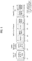
- FIG. 1 illustrates physical channels and a general signal transmission method using the physical channels in a 3GPP system.
- the UE When a UE is powered on or enters a new cell, the UE performs initial cell search (S101).
- the initial cell search involves acquisition of synchronization to a BS.
- the UE receives a synchronization signal block (SSB) from the BS.
- the SSB includes a primary synchronization signal (PSS), a secondary synchronization signal (SSS), and a physical broadcast channel (PBCH).
- PSS primary synchronization signal
- SSS secondary synchronization signal
- PBCH physical broadcast channel
- the UE synchronizes its timing to the BS and acquires information such as a cell identifier (ID) based on the PSS/SSS. Further, the UE may acquire information broadcast in the cell by receiving the PBCH from the BS.
- the UE may also monitor a DL channel state by receiving a downlink reference signal (DL RS).
- DL RS downlink reference signal
- the LTE may perform a random access procedure with the BS (S103 to S106).
- the UE may transmit a preamble on a physical random access channel (PRACH) (S103) and may receive a PDCCH and a random access response (RAR) for the preamble on a PDSCH corresponding to the PDCCH (S104).
- the UE may then transmit a physical uplink shared channel (PUSCH) by using scheduling information in the RAR (S105), and perform a contention resolution procedure including reception of a PDCCH and a PDSCH signal corresponding to the PDCCH (S106).
- PRACH physical random access channel
- RAR random access response
- the UE may receive a PDCCH and/or a PDSCH from the BS (S107) and transmit a physical uplink shared channel (PUSCH) and/or a physical uplink control channel (PUCCH) to the BS (S108), in a general LTL/DL signal transmission procedure.
- Control information that the UE transmits to the BS is generically called uplink control information (UCI).
- the UCI includes a hybrid automatic repeat and request acknowledgement/negative acknowledgement (HARQ-ACK/NACK), a scheduling request (SR), channel state information (CSI), and so on.
- the CSI includes a channel quality indicator (CQI), a precoding matrix index (PMI), a rank indication (RI), and so on.
- UCI is transmitted on a PUCCH.
- control information and data may be transmitted on a PUSCH.
- the UE may transmit the UCI aperiodically on the PUSCH, upon receipt of a request/command from a network.
- FIG. 2 illustrates a radio frame structure
- Each radio frame has a length of 10ms and is divided into two 5-ms half-frames. Each half-frame is divided into five 1-ms subframes. A subframe is divided into one or more slots, and the number of slots in a subframe depends on a subcarrier spacing (SCS).
- SCS subcarrier spacing
- Each slot includes 12 or 14 OFDM(A) symbols according to a cyclic prefix (CP). When a normal CP is used, each slot includes 14 OFDM symbols. When an extended CP is used, each slot includes 12 OFDM symbols.
- a symbol may include an OFDM symbol (or a CP-OFDM symbol) and an SC-FDMA symbol (or a discrete Fourier transform-spread-OFDM (DFT-s-OFDM) symbol).
- Table 1 exemplarily illustrates that the number of symbols per slot, the number of slots per frame, and the number of slots per subframe vary according to SCSs in a normal CP case.
- Table 2 illustrates that the number of symbols per slot, the number of slots per frame, and the number of slots per subframe vary according to SCSs in an extended CP case.
- the frame structure is merely an example, and the number of subframes, the number of slots, and the number of symbols in a frame may be changed in various manners.
- different OFDM(A) numerologies may be configured for a plurality of cells aggregated for one UE.
- the (absolute time) duration of a time resource e.g., a subframe, a slot, or a transmission time interval (TTI)
- TTI transmission time interval
- a symbol may include an OFDM symbol (or a CP-OFDM symbol) and an SC-FDMA symbol (or a discrete Fourier transform-spread-OFDM (DFT-s-OFDM) symbol).
- NR may support various numerologies (or subcarrier spacings (SCSs)) to provide various 5G services.
- SCSs subcarrier spacings
- NR may support a wide area in conventional cellular bands in an SCS of 15 kHz and support a dense urban area and a wide carrier bandwidth with lower latency in an SCS of 30/60 kHz. In an SCS of 60 kHz or above, NR may support a bandwidth higher than 24.25 GHz to overcome phase noise.
- NR frequency bands may be divided into two frequency ranges: frequency range 1 (FR1) and frequency range 2 (FR2).
- FR1 and FR2 may be configured as shown in Table 3 below.
- FR 2 may mean a millimeter wave (mmW).
- mmW millimeter wave
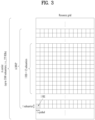
- FIG. 3 illustrates a resource grid during the duration of one slot.
- a slot includes a plurality of symbols in the time domain. For example, one slot includes 14 symbols in a normal CP case and 12 symbols in an extended CP case.
- a resource block may be defined by a plurality of (e.g., 12) consecutive subcarriers in the frequency domain.
- a bandwidth part may be defined by a plurality of consecutive (physical) RBs ((P)RBs) in the frequency domain and correspond to one numerology (e.g., SCS, CP length, and so on).
- a carrier may include up to N (e.g., 5) BWPs. Data communication may be conducted in an active BWP, and only one BWP may be activated for one UE.
- Each element in a resource grid may be referred to as a resource element (RE), to which one complex symbol may be mapped.
- RE resource element
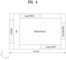
- FIG. 4 illustrates a structure of a slot.
- a frame has a self-contained structure in which a DL control channel, DL or UL data, a UL control channel, and the like may all be contained in one slot.
- the first N symbols (hereinafter, DL control region) in the slot may be used to transmit a DL control channel (e.g., PDCCH), and the last M symbols (hereinafter, LTL control region) in the slot may be used to transmit a LTL control channel (e.g., PUCCH).
- N and M are integers greater than or equal to 0.
- a resource region (hereinafter, a data region) that is between the DL control region and the LTL control region may be used for DL data (e.g., PDSCH) transmission or UL data (e.g., PUSCH) transmission.
- the GP provides a time gap for the BS and LTE to transition from the transmission mode to the reception mode or from the reception mode to the transmission mode. Some symbols at the time of DL-to-UL switching in a subframe may be configured as the GP.
- a BS transmits related signals on later-described DL channels to a UE, and the UE receives the related signals on the DL channels from the BS.
- PDSCH Physical Downlink Shared Channel
- the PDSCH delivers DL data (e.g., a DL-shared channel transport block (DL-SCH TB)) and adopts a modulation scheme such as quadrature phase shift keying (QPSK), 16-ary quadrature amplitude modulation (16QAM), 64-ary QAM (64QAM), or 256-ary QAM (256 QAM).
- a TB is encoded to a codeword.
- the PDSCH may deliver up to two codewords.
- the codewords are individually scrambled and modulated, and modulation symbols of each codeword are mapped to one or more layers.
- An OFDM signal is generated by mapping each layer together with a DMRS to resources, and transmitted through a corresponding antenna port.
- the PDSCH has two different mapping types, referred to as type A and type B.
- the mapping types are specified based on PDSCH DMRS types.
- the PDCCH delivers DCI and adopts QPSK as a modulation scheme.
- One PDCCH includes 1, 2, 4, 8, or 16 control channel elements (CCEs) according to its aggregation level (AL).
- One CCE includes 6 resource element groups (REGs), each REG being defined by one OFDM symbol by one (physical) resource block ((P)RB)).
- FIG. 5 illustrates an exemplary structure of one REG.
- D represents an RE to which DCI is mapped
- R represents an RE to which a DMRS is mapped.
- the DMRS is mapped to 1st, 5th, and 9th RE along the frequency direction in one symbol.
- the PDCCH may be transmitted in a control resource set (CORESET).
- the CORESET is defined as a set of resource element groups (REGs) with a given numerology (e.g., SCS, CP length, and so on).
- a plurality of CORESETs for one UE may overlap with each other in the time/frequency domain.
- the CORESET may be configured by system information (e.g., master information block (MIB)) or by UE-specific higher layer signaling (e.g., radio resource control (RRC) signaling).
- MIB master information block
- RRC radio resource control
- the number of RBs and the number of symbols (up to 3 symbols) included in the CORESET may be configured by higher layer signaling.
- a precoder granularity in the frequency domain is set to one of the followings by higher-layer signaling:
- the REGs of the CORESET are numbered in a time-first mapping manner. That is, the REGs are sequentially numbered in an increasing order, starting with 0 for the first OFDM symbol of the lowest-numbered RB in the CORESET.
- the LTE may obtain DCI transmitted over a PDCCH by decoding (blind decoding) a set of PDCCH candidates.
- the set of PDCCH candidates decoded by the UE is defined as a PDCCH search space set.
- a search space set may be a common search space (CSS) or a UE-specific search space (USS).
- the UE may obtain DCI by monitoring PDCCH candidates in one or more search space sets configured by an MIB or higher layer signaling.
- Each CORESET configuration may be associated with one or more search space sets, and each search space set may be associated with one CORESET configuration.
- One search space set may be determined based on the following parameters.
- Table 4 shows the characteristics of each search space type.
- Type Search Space RNTI Use Case Type0-PDCCH Common SI-RNTI on a primary cell SIB Decoding Type0A-PDCCH Common SI-RNTI on a primary cell SIB Decoding Type 1-PDCCH Common RA-RNTI or TC-RNTI on a primary cell Msg2, Msg4 decoding in RACH Type2-PDCCH Common P-RNTI on a primary cell Paging Decoding Type3-PDCCH Common INT-RNTI, SFI-RNTI, TPC-PUSCH-RNTI, TPC-PUCCH-RNTI, TPC-SRS-RNTI, C-RNTI, MCS-C-RNTI, or CS-RNTI(s) UE Specific C-RNTI, or MCS-C-RNTI, or CS-RNTI(s) User specific PDSCH decoding
- the UE transmits related signals on later-described UL channels to the BS, and the BS receives the related signals on the UL channels from the UE.
- PUSCH Physical uplink shared channel
- the PUSCH delivers LTL data (e.g., a LTL-shared channel transport block (LTL-SCH TB)) and/or UCI, in cyclic prefix-orthogonal frequency division multiplexing (CP-OFDM) waveforms or discrete Fourier transform-spread-orthogonal division multiplexing (DFT-s-OFDM) waveforms.
- LTL data e.g., a LTL-shared channel transport block (LTL-SCH TB)
- UCI cyclic prefix-orthogonal frequency division multiplexing
- CP-OFDM cyclic prefix-orthogonal frequency division multiplexing
- DFT-s-OFDM discrete Fourier transform-spread-orthogonal division multiplexing
- the UE may transmit the PUSCH in CP-OFDM waveforms
- the LTE may transmit the PUSCH in CP-OFDM waveforms or DFT-s-OFDM waveforms.
- the PUSCH transmission may be scheduled dynamically by a UL grant in DCI or semi-statically by higher-layer signaling (e.g., RRC signaling) (and/or layer 1 (L1) signaling (e.g., a PDCCH)) (a configured grant).
- the PUSCH transmission may be performed in a codebook-based or non-codebook-based manner.
- PUCCH Physical uplink control channel
- the PUCCH delivers UCI, an HARQ-ACK, and/or an SR and is classified as a short PUCCH or a long PUCCH according to the transmission duration of the PUCCH.
- Table 5 lists exemplary PUCCH formats. [Table 5] PUCCH format Length in OFDM symbols N symb PUCCH Number of bits Usage Etc 0 1 - 2 ⁇ 2 HARQ, SR Sequence selection 1 4 - 14 ⁇ 2 HARQ, [SR] Sequence modulation 2 1 - 2 >2 HARQ, CSI, [SR] CP-OFDM 3 4 - 14 >2 HARQ, CSI, [SR] DFT-s-OFDM (no UE multiplexing) 4 4 - 14 >2 HARQ, CSI, [SR] DFT-s-OFDM (Pre DFT OCC)
- PUCCH format 0 conveys UCI of up to 2 bits and is mapped in a sequence-based manner, for transmission. Specifically, the UE transmits specific UCI to the BS by transmitting one of a plurality of sequences on a PUCCH of PUCCH format 0. Only when the LTE transmits a positive SR, the LTE transmits the PUCCH of PUCCH format 0 in a PUCCH resource for a corresponding SR configuration.
- PUCCH format 1 conveys UCI of up to 2 bits and modulation symbols of the UCI are spread with an OCC (which is configured differently whether frequency hopping is performed) in the time domain.
- the DMRS is transmitted in a symbol in which a modulation symbol is not transmitted (i.e., transmitted in time division multiplexing (TDM)).
- PUCCH format 2 conveys UCI of more than 2 bits and modulation symbols of the DCI are transmitted in frequency division multiplexing (FDM) with the DMRS.
- the DMRS is located in symbols #1, #4, #7, and #10 of a given RB with a density of 1/3.
- a pseudo noise (PN) sequence is used for a DMRS sequence.
- frequency hopping may be activated.
- PUCCH format 3 does not support UE multiplexing in the same PRBS, and conveys UCI of more than 2 bits. In other words, PUCCH resources of PUCCH format 3 do not include an OCC. Modulation symbols are transmitted in TDM with the DMRS.
- PUCCH format 4 supports multiplexing of up to 4 UEs in the same PRBS, and conveys UCI of more than 2 bits.
- PUCCH resources of PUCCH format 3 includes an OCC. Modulation symbols are transmitted in TDM with the DMRS.
- the UE may be configured with a list of up to M candidate transmission configuration indication (TCI) states through RRC signaling.
- TCI transmission configuration indication
- M may be 64.
- Each TCI state may be configured with one RS set.
- the ID of each DL RS at least for the purpose of spatial QCL (QCL Type D) in the RS set may refer to one of the following DL RS types: SSB, periodic-CSI RS (P-CSI RS), semi persistent-CSI RS (SP-CSI RS), aperiodic-CSI RS (A-CSI RS), etc.
- the ID of DL RS(s) in the RS set used at least for the purpose of spatial QCL may be initialized/updated by explicit signaling
- Table 6 shows an exemplary TCI-State information element (IE).
- the TCI-State IE is associated with QCL type(s) corresponding to one or two DL RSs.
- the parameter bwp-Id indicates a DL BWP in which the RS is located
- the parameter cell indicates a carrier in which the RS is located
- the parameter referenceSignal indicates reference antenna port(s) serving as a QCL source for corresponding target antenna port(s) or an RS including the reference antenna port(s).
- the target antenna port(s) may be a channel state information-reference signal (CSI-RS), a PDCCH DMRS, or a PDSCH DMRS.
- CSI-RS channel state information-reference signal
- PDCCH DMRS PDCCH DMRS
- a PDSCH DMRS a PDSCH DMRS.
- a TCI state ID may be indicated by non-zero power (NZP) CSI-RS resource configuration information in order to indicate QCL reference information for a NZP CSI-RS.
- NZP non-zero power
- a TCI state ID may be indicated by each CORESET configuration in order to indicate QCL reference information for PDCCH DMRS antenna port(s).
- a TCI state ID may be indicated in DCI in order to indicate QCL reference information for the PDSCH DMRS antenna port(s).
- An antenna port may be defined such that a channel conveying a symbol on the antenna port is inferred from a channel conveying another symbol on the same antenna port.
- the two antenna ports may be said to be in the quasi co-located or quasi co-location (QC/QCL) relationship.
- the channel properties may include at least one of the following factors: delay spread, Doppler spread, frequency/Doppler shift, average received power, and received timing/average delay, or spatial receive (RX) parameter.
- the spatial Rx parameter refers to a spatial (RX) channel property parameter such as angle of arrival.
- the UE may be configured with a list of up to M TCI-state configurations through a higher layer parameter PDSCH-Config , where M depends on LTE capability.
- Each TCI-state includes parameters for establishing the QCL relationship between one or two DL RSs and DMRS ports of the PDSCH.
- the QCL relationship may be configured by a higher layer parameter qcl-Type1 for a first DL RS and a higher layer parameter qcl-Type2 for a second DL RS (if configured).
- the QCL types may not be the same, regardless of whether the reference is the same DL RS or different DL RSs.
- the QCL type of each DL RS is given by a higher layer parameter qcl-Type in QCL-Info and have one of the following values:
- corresponding NZP CSI-RS antenna ports may be indicated/configured to be QCL with a specific tracking reference signal (TRS) in terms of QCL-Type A and QCL with a specific SSB in terms of QCL-Type D.
- TRS tracking reference signal
- the UE may receive the corresponding NZP CSI-RS based on Doppler and delay values measured on a TRS QCL in terms of QCL-Type A and apply a reception beam used to receive an SSB QCL in terms of QCL-Type D to the reception of the corresponding NZP CSI-RS.
- the UE may receive an activation command used to map up to 8 TCI states to the code point of a DCI field ' Transmission Configuration Indication ' through medium access control (MAC) CE signaling.
- MAC medium access control
- beam reciprocity between a Tx beam and an Rx beam may or may not be established in the UL BM. If the reciprocity between the Tx beam and the Rx beam is established for both the BS and the UE, a UL beam pair may be aligned by a DL beam pair. However, if the reciprocity between the Tx beam and the Rx beam is not established for any one of the BS and the LTE, a process of determining a UL beam pair is required separately from determination of a DL beam pair.
- the BS may use the LTL BM procedure to determine a DL Tx beam without requesting the LTE to report a UE's preferred beam.
- the LTL BM may be performed based on beamformed LTL SRS transmission. Whether the UL BM is applied to an SRS resource set may be configured by usage (which is a higher layer parameter). When usage is set to 'BeamManagement(BM)', only one SRS resource may be transmitted in each of a plurality of SRS resource sets at a given time instant.
- usage which is a higher layer parameter.
- the UE may receive one or more sounding reference symbol (SRS) resource sets configured by SRS-ResourceSet (which is a higher layer parameter) (through higher layer signaling such as RRC signaling).
- SRS-ResourceSet which is a higher layer parameter
- RRC signaling higher layer signaling
- K K ⁇ 1 SRS resources
- SRS_capability the maximum value of K is indicated by a parameter SRS_capability.
- the LTL BM procedure may be divided into Tx beam sweeping of the UE and Rx beam sweeping of the BS.
- FIG. 6 illustrates an exemplary UL BM procedure based on SRSs. Specifically, FIG. 6(a) shows a process for a BS to determine an Rx beam, and FIG. 6(b) shows a process for a UE to sweep a Tx beam.
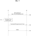
- FIG. 7 is a flowchart illustrating an exemplary LTL BM procedure based on SRSs.
- the LTE may receive RRC signaling (e.g., SRS-Config IE ) including a parameter usage set to 'beam management' from the BS (S700).
- RRC signaling e.g., SRS-Config IE
- Table 7 shows an exemplary SRS-Config IE, and the SRS-Config IE is used to configure SRS transmission.
- the SRS-Config IE includes a list of SRS-Resources and a list of SRS-ResourceSets. Each SRS resource set means a set of SRS-resources.
- the network may trigger transmission of an SRS resource set based on configured aperiodicSRS-ResourceTrigger (L1 DCI).
- L1 DCI aperiodicSRS-ResourceTrigger
- usage is a higher layer parameter indicating whether an SRS resource set is used for beam management, codebook-based transmission, or non-codebook-based transmission.
- the parameter usage corresponds to an L1 parameter ' SRS-SetUse '.
- a parameter ' spatialRelationInfo ' indicates the configuration of a spatial relation between a reference RS and a target SRS.
- the reference RS may be an SSB, a CSI-RS, or an SRS corresponding to the L1 parameter ' SRS-SpatialRelationInfo '.
- the parameter usage is configured for each SRS resource set.
- the UE may determine a Tx beam for an SRS resource to be transmitted based on SRS-SpatialRelationInfo included in the SRS-Config IE (S710).
- SRS-SpatialRelationInfo may be configured for each SRS resource and indicate whether to apply the same beam as that used for the SSB, CSI-RS, or SRS for each SRS resource.
- SRS-SpatialRelationInfo may or may not be configured for each SRS resource.
- the UE may apply the same beam as that used for the SSB, CSI-RS, or SRS to the SRS resource and transmit the SRS resource. However, if SRS-SpatialRelationInfo is not configured for the SRS resource, the UE may arbitrarily determine the Tx beam and transmits the SRS on the determined Tx beam (S720).
- a beam may be determined and transmitted similarly to the above.
- the UE may or may not receive feedback on the SRS from the BS as described in the following three cases (S730).
- NR In 3GPP NR systems, operations in a band below 52.6 GHz are defined. In addition, discussion is ongoing to operate the NR systems in licensed and/or unlicensed bands of 60/70 GHz (e.g., bands from 52.6 GHz to 71 GHz). In the NR system operating in the 60/70 GHz bands (such a system is referred to as high frequency (HF)-NR for convenience), a new OFDM numerology based on a large SCS (e.g., 240 kHz, 480 kHz, 960 kHz, etc.) compared to the SCS of the legacy NR system (e.g.
- a large SCS e.g., 240 kHz, 480 kHz, 960 kHz, etc.
- the present disclosure proposes a signal/data transmission/reception method in consideration of the effect of the beam switching time.
- millimeter wave bands are defined as FR2 as shown in Table 3.
- the SCS of an SS/PBCH block in FR2 bands may be either 120 or 240 kHz, and the SCS of other signals/channels may be either 60 or 120 kHz.
- an SCS larger than those applied to the FR2 bands may be introduced. If the scalability of an OFDM symbol duration and a CP length defined in the current NR system is maintained, an OFDM symbol duration and a CP length may be defined for each SCS as shown in Table 8 below. [Table 8] SCS [kHz] 120 240 480 960 Symbol duration 8.33 us 4.17 us 2.08 us 1.04 us CP length 586 ns 293 ns 146 ns 73 ns
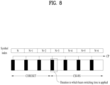
- the beam switching time may affect signal transmission and reception of the UE.
- the SCS is set 960 kHz as shown in Table 8
- the LTE may perform signal transmission and reception in which beam switching between symbol #n and symbol #(n+1) is required.
- a beam switching time required to perform the beam switching may be required.
- the beam switching time is longer than the CP length (e.g., 73 ns)
- distortion may occur during signal transmission and reception.
- the difference between the CP length and the beam switching time is significantly small, distortion may occur during signal transmission and reception.
- the beam switching time 200 ns
- the CP length e.g., 146 ns
- the LTE performs signal transmission and reception where beam switching between symbol #n and symbol #(n+1) is required, the difference between the CP length (e.g., 146 ns) and the beam switching time (140 ns) is significantly reduced, and as a result, distortion may occur during the signal transmission and reception.
- the present disclosure proposes methods for solving the degradation of signal transmission/reception performance, which may be caused by the beam switching time of the LTE or BS.
- the UE when the UE receives DL signal #2 in a symbol immediately after receiving DL signal #1 (or when the BS transmits DL signal #2 in a symbol immediately after transmitting DL signal #1), the UE (or BS) may need to perform beam switching. In this case, if the CP of DL signal #1 is not sufficient to perform the beam switching, the UE may experience performance degradation in receiving DL signal #2 (or DL signal #1) (or the BS may experience performance degradation in transmitting DL signal #2 (or DL signal #1)).
- the LTE may need to perform beam switching.
- the UE may experience performance degradation in transmitting UL signal #2 (or UL signal #1) (or the BS may experience performance degradation in receiving UL signal #2 (or UL signal #1)).
- the present disclosure proposes a DL signal reception (or transmission) method for solving performance degradation in DL signal transmission/reception and a LTL signal transmission (or reception) method for solving performance degradation in LTL signal transmission/reception.
- a DL signal/channel may mean a DL signal, a DL control channel, or a DL data channel supported by NR.
- the DL signal/channel may include a CSI-RS, a PDCCH (or CORESET), or a PDSCH.
- a (DL) beam switching time it may mean that TCI state IDs associated with two adjacent DL signals/channels are different from each other (in the time domain), RSs in the QCL relationship are different from each other, or associated SSB indices are different from each other.
- a LTL signal/channel may mean a LTL signal, a LTL control channel, or a UL data channel supported by NR.
- the UL signal/channel may be a PRACH, a PUSCH, a PUCCH, or a sounding reference signal (SRS).
- SRS sounding reference signal
- signal/channel #M and signal/channel #N when there are signal/channel #M and signal/channel #N where M ⁇ N, it may mean that signal/channel #M is earlier than signal/channel #N in the time domain (signal/channel #M precedes signal/channel #N in the time domain).
- signal/channel #M and signal/channel #N may be transmitted or received on different carriers. For example, signal/channel #M may be transmitted (or received) on carrier #1, and signal/channel #N may be transmitted (or received) on carrier #2, where carrier #1 and carrier #2 may be belong to the same band and in the carrier aggregation relationship (i.e., intra-band carrier aggregation).
- the methods proposed in the present disclosure may be applied when a beam switching time is required (or necessary).
- the methods proposed in the present disclosure may be applied only when the beam switching time is more than a specific value (e.g., CP length).
- the beam switching time may be predefined or determined based on UE capability (signaling). Whether the beam switching time is more than the specific value (e.g., CP length) may be determined based on a combination of the beam switching time and an SCS applied to a signal/channel/BWP. Alternatively, when the beam switching time is fixed, whether the beam switching time is more than the specific value may be determined based on the SCS applied to the signal/channelBWP.
- the methods proposed in this specification are not applied, the beam switching time may not be considered when a signal/channel is transmitted/received.
- Receiver (Entity A) (e.g., UE):
- the at least n-symbol gap may mean a time gap composed of n symbols. In this case, no modulation symbols may be mapped to the first m symbols of DL signal/channel #2 (e.g., rate-matching).
- the UE may receive DL signal/channel #2 from the first symbol but exclude the first m symbols of DL signal/channel #2 from decoding (e.g., puncturing). That is, the LTE may receive DL signal/channel #2 from the first symbol but puncture the first m symbols of DL signal/channel #2 during decoding.
- decoding e.g., puncturing
- no modulation symbols may be mapped to the last m symbols of DL signal/channel #1 (e.g., rate matching).
- the UE may receive DL signal/channel #1 in a duration of all allocated symbols but exclude the last m symbols of DL signal/channel #1 from decoding (e.g., puncturing).
- whether rate matching (or puncturing) is performed on the last m symbols of DL signal/channel #1 or on the first m symbols of DL signal/channel #2 may be determined by priorities according to [Method #1-2] below or configured by higher layer signaling. That is, if DL signal/channel #1 has a higher priority according to [Method #1-2] proposed below, the UE may perform the rate matching (or puncturing) on the first m symbols of DL signal/channel #2. Alternatively, if DL signal/channel #2 has a higher priority according to [Method #1-2] proposed below, the LTE may perform the rate matching (or puncturing) on the last m symbols of DL signal/channel #1. Alternatively, whether the rate matching (or puncturing) is performed on the last m symbols of DL signal/channel #1 or on the first m symbols of DL signal/channel #2 may be directly configured by higher layer signaling.
- the UE may not receive DL signal/channel #2 (or DL signal/channel #1).
- the UE may receive by applying the beam switching time only to a specific DL signal/channel.
- a time duration e.g., symbols, samples within a symbol, etc.
- the time duration may be excluded from the reception at the sample level (e.g., at the sub-symbol level).
- Applying the beam switching time to the specific DL signal/channel may mean that beam switching is performed in a time duration including the specific DL signal/channel.
- applying the beam switching time to the specific DL signal/channel may mean that rate matching or puncturing is performed on some symbols or samples included in the specific DL signal/channel.
- the priorities of DL signal/channel #1 and DL signal/channel #2 may be determined according to a predetermined criterion, and the UE may apply the beam switching time only to a DL signal/channel having a lower priority among DL signals/channels #1 and #2. Specifically, some or all of the following options may be applied as the criterion for determining the priorities.
- Method #1-3 The beam switching time is divided and applied to two consecutive DL signals/channels.
- the UE may receive DL signal/channel #1 and DL signal/channel #2 by dividing the beam switching time to the two consecutive DL signals/channels.
- a time duration e.g., symbols, samples within a symbol, etc.
- the time duration may be excluded from the reception at the sample level (e.g., at the sub-symbol level).
- the UE may apply the beam switching time to DL signal/channel #1 for a time corresponding to ⁇ beam switching time/alpha ⁇ and apply the beam switching time to DL signal/channel #2 for a time corresponding to ⁇ 1-(beam switching time/alpha) ⁇ .
- the value of alpha may be 2, but the present disclosure is not limited thereto.
- both DL signal/channel #1 and DL signal/channel #2 are PDCCHs (or when both DL signal/channel #1 and DL signal/channel #2 are either PDSCHs or CSI-RSs), the above-described method may be applied.
- both DL signal/channel #1 and DL signal/channel #2 are PDSCHs
- both DL signal/channel #1 and DL signal/channel #2 are semi-persistent scheduling (SPS) PDSCHs (or when both DL signal/channel #1 and DL signal/channel #2 are PDSCHs indicated by DL assignment)
- SPS semi-persistent scheduling
- the above-described method may be applied.
- both DL signal/channel #1 and DL signal/channel #2 are CSI-RSs
- both DL signal/channel #1 and DL signal/channel #2 are periodic (or semi-persistent) CSI-RSs (or when both DL signal/channel #1 and DL signal/channel #2 are aperiodic CSI-RSs)
- the above-described method may be applied.
- the LTE may expect that no DM-RS is indicated in the last symbol of DL signal/channel #1 and/or the first symbol of DL signal/channel #2 (alternatively, the UE may not expect that a DM-RS is indicated in the corresponding symbol).
- the LTE may report to the BS whether to divide and apply the beam switching time to the two consecutive DL signals/channels or to apply the beam switching time only to a specific DL signal/channel.
- the UE may report to the BS that the UE prefers to apply the beam switching time only to the DL signal/channel following in the time domain. After reporting to the BS, the UE may apply the beam switching time to the first symbol of DL signal/channel #2.
- FFT fast Fourier transform
- no modulation symbols may be mapped to the first m symbols of UL signal/channel #2 (e.g., rate-matching).
- the UE may generate LTL signal/channel #2 from the first symbol and puncture the first m symbols in mapping/transmission of UL signal/channel #2.
- the LTE may generate LTL signal/channel #1 in a duration of all allocated symbols but exclude the last m symbols from mapping/transmission of UL signal/channel #1 (e.g., puncturing).
- whether rate matching (or puncturing) is performed on the last m symbols of UL signal/channel #1 or on the first m symbols of UL signal/channel #2 may be determined by priorities according to [Method #2-2] below or configured by higher layer signaling. That is, if the priority of LTL signal/channel #1 determined by [Method #2-2] is higher than the priority of LTL signal/channel #2, the LTE may perform the rate matching (or puncturing) on the first m symbols of LTL signal/channel #2. Alternatively, if the priority of UL signal/channel #2 is higher than the priority of UL signal/channel #1, the UE may perform the rate matching (or puncturing) on the last m symbols of UL signal/channel #1. Alternatively, whether the rate matching (or puncturing) is performed on the last m symbols of UL signal/channel #1 or on the first m symbols of UL signal/channel #2 may be directly configured by higher layer signaling.
- Method #2-2 The beam switching time is applied only to a specific UL signal/channel according to priorities.
- the UE may transmit UL signal/channel #1 and UL signal/channel #2 by applying the beam switching time only to a specific UL signal/channel.
- a time duration e.g., symbols, samples within a symbol, etc.
- the time duration may be excluded from the transmission at the sample level (e.g., at the sub-symbol level).
- the present disclosure is not limited thereto.
- Applying the beam switching time to the specific UL signal/channel may mean that beam switching is performed in a time duration including the specific UL signal/channel.
- applying the beam switching time to the specific UL signal/channel may mean that rate matching or puncturing is performed on some symbols or samples included in the specific UL signal/channel.
- the priorities of UL signal/channel #1 and UL signal/channel #2 may be determined according to a predetermined criterion, and the UE may apply the beam switching time only to a LTL signal/channel having a lower priority among UL signals/channels #1 and #2. Specifically, some or all of the following options may be applied as the criterion for determining the priorities.
- Method #2-3 The beam switching time is divided and applied to two consecutive UL signals/channels.
- the LTE may transmit the two UL signals/channels by dividing the beam switching time to the two consecutive UL signals/channels.
- a time duration e.g., symbols, samples within a symbol, etc.
- the time duration may be excluded from the transmission at the sample level (e.g., at the sub-symbol level).
- the UE may apply the beam switching time to UL signal/channel #1 for a time corresponding to ⁇ beam switching time/alpha ⁇ and apply the beam switching time to UL signal/channel #2 for a time corresponding to ⁇ 1-(beam switching time/alpha) ⁇ .
- the value of alpha may be 2, but the present disclosure is not limited thereto.
- both UL signal/channel #1 and UL signal/channel #2 are PUCCHs (or when both UL signal/channel #1 and UL signal/channel #2 are either PUSCHs or SRSs), the above-described method may be applied.
- both UL signal/channel #1 and UL signal/channel #2 are PUCCHs
- both UL signal/channel #1 and UL signal/channel #2 are CG PUSCHs
- both UL signal/channel #1 and UL signal/channel #2 are PUSCHs indicated by UL grants
- the above-described method may be applied.
- both LTL signal/channel #1 and UL signal/channel #2 are SRSs
- both UL signal/channel #1 and LTL signal/channel #2 are periodic (or semi-persistent) SRSs (or when both LTL signal/channel #1 and LTL signal/channel #2 are aperiodic SRSs
- the above-described method may be applied.
- the LTE may expect that no DM-RS is indicated in the last symbol of LTL signal/channel #1 and/or the first symbol of UL signal/channel #2 (alternatively, the UE may not expect that a DM-RS is indicated in the corresponding symbol). That is, the UE may expect that no DM-RS is transmitted in the last symbol of UL signal/channel #1 and/or the first symbol of UL signal/channel #2 (alternatively, the UE may not expect that a DM-RS is transmitted in the last symbol of LTL signal/channel #1 and/or the first symbol of LTL signal/channel #2).
- the LTE may report to the BS whether to divide and apply the beam switching time to the two consecutive LTL signals/channels or to apply the beam switching time only to a specific UL signal/channel.
- the UE may report to the BS that the UE prefers to apply the beam switching time only to the UL signal/channel following in the time domain. After reporting to the BS, the UE may apply the beam switching time to the first symbol of UL signal/channel #2.
- the proposed methods related to UL transmission may be applied differently depending on which waveform is configured for the UL transmission.
- a UL signal/channel in which DFT-s-OFDM is configured may be recovered even if the UL signal/channel is punctured in the time domain for a predetermined period of time.
- a LTL signal/channel configured with a CP-OFDM waveform if the UL signal/channel is punctured in the time domain for a predetermined period of time or more, all subcarriers may be affected, and as a result, it may be difficult to recover the corresponding UL signal/channel.
- [Method #2-2/3/4] described above may be applied to the UL signal/channel in which DFT-s-OFDM is configured, and [Method #2-1] described above may be applied to the UL signal/channel in which OFDM is configured.
- the beam switching time when applied to DL signal/channel #2 or UL signal/channel #2 in the proposed methods, it may affect a time region longer than the CP length, it may be defined/configured in advance that the first symbol is configured by extending the CP of the second symbol of DL signal/channel #2 or UL signal/channel #2.
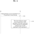
- FIG. 9 is a flowchart illustrating operations of a UE according to the proposed embodiments.
- the UE may transmit a first UL signal by applying a first beam (S900).
- the UE may perform a beam switching operation for switching the first beam to a second beam (S910) and transmit a second UL signal by applying the second beam (S920).
- the first UL signal and the second LTL signal may include at least one of a PRACH, a PUSCH, a PUCCH, or an SRS.
- the beam switching operation may be required between the first UL signal and the second UL signal as described above in [Method #2-1] to [Method #2-4].
- a beam switching time required for performing the beam switching operation may be required between the first UL signal and the second LTL signal.
- the first LTL signal and the second LTL signal may correspond to LTL signal/channel #1 and UL signal/channel #2 in [Method #2-1] to [Method #2-4], respectively.
- last several symbols of the first LTL signal or first several symbols of the second LTL signal may be excluded from transmission of the first UL signal and the second UL signal.
- the last several symbols of the first LTL signal or the first several symbols of the second LTL signal may be excluded from transmission of the first LTL signal and the second LTL signal.
- the interval between the first UL signal and the second UL signal being smaller than the duration of the predetermined number of symbols may include the following cases: when the beam switching time is greater than the CP length of the first or second UL signal (or the duration of the predetermined number of symbols); when the beam switching time reported by signaling of LTE capability is greater than the CP length of the first or second LTL signal (or the duration of the predetermined number of symbols); or when the beam switching time is smaller than the CP length (or the duration of the predetermined number of symbols) and the difference between the beam switching time and the CP length (or the duration of the predetermined number of symbols) is smaller than or equal to a threshold.
- the above-described case may occur when the CP length decreases due to use of a relatively large SCS (e.g., 480 or 960 kHz).
- a relatively large SCS e.g., 480 or 960 kHz.
- the last several symbols of the first LTL signal or the first several symbols of the second LTL signal may be excluded from transmission of the first UL signal and the second UL signal in order to secure the beam switching time.
- the last m symbols of the first LTL signal or the first m symbols of the second UL signal may be excluded from transmission of the first UL signal and the second LTL signal, where m may be smaller than or equal to n.
- Excluding the last several symbols of the first UL signal (or the first several symbols of the second LTL signal) from the transmission of the first UL signal (or the second LTL signal) may mean that no modulation symbols are mapped to the last several symbols of the first UL signal (or the first several symbols of the second UL signal) by performing rate matching.
- excluding the last several symbols of the first UL signal (or the first several symbols of the second UL signal) from the transmission of the first UL signal (or the second UL signal) may mean that the first UL channel (or the second UL channel) is generated for all symbol durations allocated for the first LTL channel (or the second LTL channel), but the last several symbols of the first LTL channel (or the first several symbols of the second UL channel) are excluded from the mapping/transmission process.
- a time duration corresponding to the last several symbols of the first UL signal or the first several symbols of the second UL signal may be used as the beam switching time.
- the use of the beam switching time may mean that the beam switching time is applied as described above in [Method #2-1] to [Method #2-4].
- the UE may use the time duration corresponding to the last several symbols of the first UL signal as the beam switching time. That is, the UE may apply the beam switching time to some symbols of a UL signal having a lower priority among the two UL signals. Accordingly, even when the interval between the first UL signal and the second UL signal is not sufficient to perform the beam switching operation, the beam switching time may be effectively secured, thereby preventing degradation of signal transmission/reception performance.
- Receiver (Entity B) (e.g., BS):
- the at least n-symbol gap may mean a time gap composed of n symbols.
- no modulation symbols may be mapped to the first m symbols of DL signal/channel #2 (e.g., rate-matching).
- the BS may generate DL signal/channel #2 from the first symbol but puncture the first m symbols in mapping/transmission of DL signal/channel #2.
- no modulation symbols may be mapped to the last m symbols of DL signal/channel #1 (e.g., rate matching).
- the BS may generate DL signal/channel #1 during all symbol durations allocated for DL signal/channel #1 but may exclude the last m symbols from the transmission of DL signal/channel #1 (e.g., puncturing).
- whether rate matching (or puncturing) is performed on the last m symbols of DL signal/channel #1 or on the first m symbols of DL signal/channel #2 may be determined by priorities according to [Method #1A-2] below or configured by higher layer signaling. That is, if DL signal/channel #1 has a higher priority according to [Method #1A-2] proposed below, the BS may perform the rate matching (or puncturing) on the first m symbols of DL signal/channel #2. Alternatively, if DL signal/channel #2 has a higher priority according to [Method #1A-2] proposed below, the BS may perform the rate matching (or puncturing) on the last m symbols of DL signal/channel #1. Alternatively, whether the rate matching (or puncturing) is performed on the last m symbols of DL signal/channel #1 or on the first m symbols of DL signal/channel #2 may be directly configured by higher layer signaling.
- Method #1A-2 The beam switching time is applied only to a specific DL signal/channel according to priorities.
- the BS may expect that the UE will receive by applying the beam switching time only to a specific DL signal/channel, or the BS may transmit by applying the beam switching time only to the specific DL signal/channel.
- a time duration e.g., symbols, samples within a symbol, etc.
- the time duration may be excluded from the transmission at the sample level (e.g., at the sub-symbol level).
- Applying the beam switching time to the specific DL signal/channel may mean that beam switching is performed in a time duration including the specific DL signal/channel.
- applying the beam switching time to the specific DL signal/channel may mean that rate matching or puncturing is performed on some symbols or samples included in the specific DL signal/channel.
- the priorities of DL signal/channel #1 and DL signal/channel #2 may be determined according to a predetermined criterion, and the BS may transmit DL signals/channels #1 and #2 by applying the beam switching time only to a DL signal/channel having a lower priority among DL signals/channels #1 and #2.
- the BS may expect that the UE will receive DL signals/channels #1 and #2 by applying the beam switching time only to the DL signal/channel having the lower priority.
- some or all of the following options may be applied as the criterion for determining the priorities.
- Method #1A-3 The beam switching time is divided and applied to two consecutive DL signals/channels.
- the BS may expect that the UE will receive DL signal/channel #1 and DL signal/channel #2 by dividing the beam switching time to the two consecutive DL signals/channels.
- the BS may transmit DL signal/channel #1 and DL signal/channel #2 by dividing the beam switching time to the two consecutive DL signals/channels.
- a time duration e.g., symbols, samples within a symbol, etc.
- the time duration may be excluded from the transmission at the sample level (e.g., at the sub-symbol level).
- the BS may apply the beam switching time to DL signal/channel #1 for a time corresponding to ⁇ beam switching time/alpha ⁇ and apply the beam switching time to DL signal/channel #2 for a time corresponding to ⁇ 1-(beam switching time/alpha) ⁇ .
- the value of alpha may be 2, but the present disclosure is not limited thereto.
- both DL signal/channel #1 and DL signal/channel #2 are PDCCHs (or when both DL signal/channel #1 and DL signal/channel #2 are either PDSCHs or CSI-RSs), the above-described method may be applied.
- both DL signal/channel #1 and DL signal/channel #2 are PDSCHs
- both DL signal/channel #1 and DL signal/channel #2 are SPS PDSCHs
- both DL signal/channel #1 and DL signal/channel #2 are PDSCHs indicated by DL assignment
- the above-described method may be applied.
- both DL signal/channel #1 and DL signal/channel #2 are CSI-RSs
- both DL signal/channel #1 and DL signal/channel #2 are periodic (or semi-persistent) CSI-RSs (or when both DL signal/channel #1 and DL signal/channel #2 are aperiodic CSI-RSs)
- the above-described method may be applied.
- the BS may be constrained to indicate no DM-RS in the last symbol of DL signal/channel #1 and/or the first symbol of DL signal/channel #2.
- the BS may receive from the UE a report on whether the UE divides and applies the beam switching time to the two consecutive DL signals/channels or applies the beam switching time only to a specific DL signal/channel.
- the UE may report to the BS that the UE prefers to apply the beam switching time only to the DL signal/channel following in the time domain. After reporting to the BS, the UE may apply the beam switching time to the first symbol of DL signal/channel #2.
- the BS may recognize that the UE prefers to apply the beam switching time only to the DL signal/channel following in the time domain, based on information reported by the UE. Accordingly, the BS may expect that the UE will apply the beam switching time to the first symbol of DL signal/channel #2.
- no modulation symbols may be mapped to the first m symbols of UL signal/channel #2 (e.g., rate-matching).
- the BS may receive UL signal/channel #2 from the first symbol but exclude the first m symbols of LTL signal/channel #2 from decoding (e.g., puncturing).
- the BS may receive DL signal/channel #1 in a duration of all allocated symbols but exclude the last m symbols of UL signal/channel #1 from decoding (e.g., puncturing).
- whether rate matching (or puncturing) is performed on the last m symbols of UL signal/channel #1 or on the first m symbols of UL signal/channel #2 may be determined by priorities according to [Method #2A-2] below or configured by higher layer signaling. That is, if the priority of LTL signal/channel #1 determined by [Method #2-2] is higher than the priority of LTL signal/channel #2, the BS may perform the rate matching (or puncturing) on the first m symbols of LTL signal/channel #2. Alternatively, if the priority of LTL signal/channel #2 is higher than the priority of LTL signal/channel #1, the BS may perform the rate matching (or puncturing) on the last m symbols of UL signal/channel #1. Alternatively, whether the rate matching (or puncturing) is performed on the last m symbols of UL signal/channel #1 or on the first m symbols of UL signal/channel #2 may be directly configured by higher layer signaling.
- Method #2A-2 The beam switching time is applied only to a specific UL signal/channel according to priorities.
- the BS may expect that the UE will transmit by applying the beam switching time only to a specific UL signal/channel.
- the BS may receive UL signal/channel #1 and UL signal/channel #2 by applying the beam switching time only to the specific UL signal/channel.
- a time duration e.g., symbols, samples within a symbol, etc.
- the time duration may be excluded from the reception at the sample level (e.g., at the sub-symbol level).
- the present disclosure is not limited thereto.
- Applying the beam switching time to the specific UL signal/channel may mean that beam switching is performed in a time duration including the specific UL signal/channel.
- applying the beam switching time to the specific UL signal/channel may mean that rate matching or puncturing is performed on some symbols or samples included in the specific UL signal/channel.
- the priorities of UL signal/channel #1 and UL signal/channel #2 may be determined according to a predetermined criterion.
- the BS may receive by applying the beam switching time only to a UL signal/channel having a lower priority among UL signals/channels #1 and #2 (alternatively, the BS may expect that the UE will transmit by applying the beam switching time only to the UL signal/channel having the lower priority among UL signals/channels #1 and #2).
- some or all of the following options may be applied as the criterion for determining the priorities.
- Method #2A-3 The beam switching time is divided and applied to two consecutive UL signals/channels.
- the BS may expect that the UE will transmit the two LTL signals/channels by dividing the beam switching time to the two consecutive LTL signals/channels.
- the BS may receive the two LTL signals/channels by dividing the beam switching time to the two consecutive UL signals/channels.
- a time duration e.g., symbols, samples within a symbol, etc.
- the time duration may be excluded from the reception at the sample level (e.g., at the sub-symbol level).
- the BS may expect that the UE will apply the beam switching time to UL signal/channel #1 for a time corresponding to ⁇ beam switching time/alpha ⁇ and apply the beam switching time to LTL signal/channel #2 for a time corresponding to ⁇ 1-(beam switching time/alpha) ⁇ .
- the value of alpha may be 2, but the present disclosure is not limited thereto.
- both LTL signal/channel #1 and LTL signal/channel #2 are PUCCHs (or when both LTL signal/channel #1 and UL signal/channel #2 are either PUSCHs or SRSs), the above-described method may be applied.
- both UL signal/channel #1 and UL signal/channel #2 are PUCCHs
- both UL signal/channel #1 and UL signal/channel #2 are CG PUSCHs
- both UL signal/channel #1 and UL signal/channel #2 are PUSCHs indicated by UL grants
- the above-described method may be applied.
- both UL signal/channel #1 and UL signal/channel #2 are SRSs
- both UL signal/channel #1 and UL signal/channel #2 are periodic (or semi-persistent) SRSs (or when both LTL signal/channel #1 and LTL signal/channel #2 are aperiodic SRSs)
- the above-described method may be applied.
- the BS may be constrained to indicate no DM-RS in the last symbol of UL signal/channel #1 and/or the first symbol of UL signal/channel #2. That is, the BS may impose a restriction such that no DM-RS is transmitted in the last symbol of LTL signal/channel #1 and/or the first symbol of UL signal/channel #2.
- the BS may receive from the UE a report on whether the UE divides and applies the beam switching time to the two consecutive UL signals/channels or applies the beam switching time only to a specific UL signal/channel.
- the UE may report to the BS that the UE prefers to apply the beam switching time only to the UL signal/channel following in the time domain. After reporting to the BS, the UE may apply the beam switching time to the first symbol of UL signal/channel #2.
- the BS may recognize that the UE prefers to apply the beam switching time only to the DL signal/channel following in the time domain, based on information reported by the UE. Accordingly, the BS may expect that the LTE will apply the beam switching time to the first symbol of DL signal/channel #2.
- the proposed methods related to UL transmission may be applied differently depending on which waveform is configured for the UL transmission.
- a UL signal/channel in which DFT-s-OFDM is configured may be recovered even if the UL signal/channel is punctured in the time domain for a predetermined period of time.
- a LTL signal/channel configured with a CP-OFDM waveform if the UL signal/channel is punctured in the time domain for a predetermined period of time or more, all subcarriers may be affected, and as a result, it may be difficult to recover the corresponding UL signal/channel.
- [Method #2A-2/3/4] described above may be applied to the UL signal/channel in which DFT-s-OFDM is configured, and [Method #2A-1] described above may be applied to the UL signal/channel in which OFDM is configured.
- the beam switching time when applied to DL signal/channel #2 or UL signal/channel #2 in the proposed methods, it may affect a time region longer than the CP length, it may be defined/configured in advance that the first symbol is configured by extending the CP of the second symbol of DL signal/channel #2 or UL signal/channel #2.
- FIG. 10 is a flowchart illustrating operations of a BS according to the proposed embodiments.
- the BS may receive a first UL signal by applying a first beam (S1000).
- the UE may perform a beam switching operation for switching the first beam to a second beam (S1010) and receive a second UL signal by applying the second beam (S1020).
- the first UL signal and the second UL signal may include at least one of a PRACH, a PUSCH, a PUCCH, or an SRS.
- the beam switching operation may be required between the first UL signal and the second UL signal as described above in [Method #2A-1] to [Method #2A-4].
- a beam switching time required for performing the beam switching operation may be required between the first UL signal and the second LTL signal.
- the first LTL signal and the second LTL signal may correspond to LTL signal/channel #1 and LTL signal/channel #2 in [Method #2A-1] to [Method #2A-4], respectively.
- last several symbols of the first LTL signal or first several symbols of the second LTL signal may be excluded from receiving the first UL signal and the second UL signal.
- the last several symbols of the first UL signal or the first several symbols of the second UL signal may be excluded from receiving the first UL signal and the second UL signal.
- the BS may expect that the LTE will exclude the last several symbols of 1 LTL signal or the first several symbols of the second UL signal from transmission of the first UL signal and the second LTL signal.
- the interval between the first UL signal and the second UL signal being smaller than the duration of the predetermined number of symbols may include the following cases: when the beam switching time is greater than the CP length of the first or second UL signal (or the duration of the predetermined number of symbols); when the beam switching time reported by signaling of LTE capability is greater than the CP length of the first or second LTL signal (or the duration of the predetermined number of symbols); or when the beam switching time is smaller than the CP length (or the duration of the predetermined number of symbols) and the difference between the beam switching time and the CP length (or the duration of the predetermined number of symbols) is smaller than or equal to a threshold.
- the last several symbols of the first UL signal or the first several symbols of the second UL signal may be excluded from receiving the first UL signal and the second LTL signal in order to secure the beam switching time.
- the last m symbols of the first LTL signal or the first m symbols of the second LTL signal may be excluded from receiving the first UL signal and the second UL signal, where m may be smaller than or equal to n.
- Excluding the last several symbols of the first UL signal (or the first several symbols of the second LTL signal) from the reception of the first LTL signal (or the second LTL signal) may mean that no modulation symbols are mapped to the last several symbols of the first UL signal (or the first several symbols of the second UL signal) by performing rate matching.
- excluding the last several symbols of the first UL signal (or the first several symbols of the second LTL signal) from the reception of the first UL signal (or the second LTL signal) may mean that the BS may receive the first UL channel (or the second UL channel) for all symbol durations allocated for the first UL channel (or the second UL channel) but exclude the last several symbols of the first UL channel (or the first several symbols of the second LTL channel) from decoding.
- a time duration corresponding to the last several symbols of the first UL signal or the first several symbols of the second UL signal may be used as the beam switching time.
- the use of the beam switching time may mean that the beam switching time is applied as described above in [Method #2A-1] to [Method #2A-4].
- Whether the time duration corresponding to the last several symbols of the first UL signal or the time duration corresponding to the first several symbols of the second LTL signal is used as the beam switching time may be determined according to the priorities of the first UL signal and the second UL signal.
- the priorities of the first UL signal and the second LTL signal may be determined according to at least one of Options 1 to 7 of [Method #2A-2] described above.
- the time duration corresponding to the first several symbols of the second UL signal may be used as the beam switching time.
- the time duration corresponding to the last several symbols of the first UL signal may be used as the beam switching time. That is, the LTE may apply the beam switching time to several symbols of a LTL signal having a lower priority among the two UL signals.
- the BS may expect the UE applies the beam switching time to the several symbols of the LTL signal with the lower priority. Accordingly, even when the interval between the first LTL signal and the second LTL signal is not sufficient to perform the beam switching operation, the beam switching time may be effectively secured, thereby preventing degradation of signal transmission/reception performance.
- the BS may instruct or configure the UE to receive DL signal/channel #1 and DL signal/channel #2 with no symbol gap as shown in FIG. 11 .
- the BS and LTE may operate in an HF-NR system (e.g., frequency bands from 52.6 GHz to 71 GHz, which are referred to as FR3 for convenience).
- FR3 frequency bands from 52.6 GHz to 71 GHz, which are referred to as FR3 for convenience.
- the UE may receive the DL signals/channels by applying the beam switching time only to the specific DL signal/channel according to [Method #1-2].
- the UE may receive the DL signals/channels by dividing and applying the beam switching time to the two consecutive DL signals/channels according to [Method #1-3].
- the two DL signals/channels may be transmitted/received according to [Method #1-1] or [Method #1-4].
- the BS may instruct or configure the UE to transmit LTL signal/channel #1 and LTL signal/channel #2 with no symbol gap as shown in FIG. 12 .
- the BS and UE may operate in an HF-NR system (e.g., frequency bands from 52.6 GHz to 71 GHz, which are referred to as FR3 for convenience).
- FR3 frequency bands from 52.6 GHz to 71 GHz, which are referred to as FR3 for convenience.
- the LTE may transmit the UL signals/channels by applying the beam switching time only to a specific UL signal/channel according to [Method #2-2].
- the UE may transmit the UL signals/channels by dividing the beam switching time to the two consecutive UL signals/channels according to [Method #2-3].
- the two LTL signals/channels may be transmitted/received according to [Method #2-1] or [Method #2-4].
- FIG. 13 illustrates a communication system 1 applied to the present disclosure.
- a communication system 1 applied to the present disclosure includes wireless devices, Base Stations (BSs), and a network.
- the wireless devices represent devices performing communication using Radio Access Technology (RAT) (e.g., 5G New RAT (NR)) or Long-Term Evolution (LTE)) and may be referred to as communication/radio/5G devices.
- RAT Radio Access Technology
- the wireless devices may include, without being limited to, a robot 100a, vehicles 100b-1 and 100b-2, an extended Reality (XR) device 100c, a hand-held device 100d, a home appliance 100e, an Internet of Things (IoT) device 100f, and an Artificial Intelligence (AI) device/server 400.
- RAT Radio Access Technology
- NR 5G New RAT
- LTE Long-Term Evolution
- the wireless devices may include, without being limited to, a robot 100a, vehicles 100b-1 and 100b-2, an extended Reality (XR) device 100c, a hand-held device 100d, a home appliance 100e, an Internet of Things
- the vehicles may include a vehicle having a wireless communication function, an autonomous driving vehicle, and a vehicle capable of performing communication between vehicles.
- the vehicles may include an Unmanned Aerial Vehicle (UAV) (e.g., a drone).
- UAV Unmanned Aerial Vehicle
- the XR device may include an Augmented Reality (AR)/Virtual Reality (VR)/Mixed Reality (MR) device and may be implemented in the form of a Head-Mounted Device (HMD), a Head-Up Display (HUD) mounted in a vehicle, a television, a smartphone, a computer, a wearable device, a home appliance device, a digital signage, a vehicle, a robot, etc.
- the hand-held device may include a smartphone, a smartpad, a wearable device (e.g., a smartwatch or a smartglasses), and a computer (e.g., a notebook).
- the home appliance may include a TV, a refrigerator, and a washing machine.
- the IoT device may include a sensor and a smartmeter.
- the BSs and the network may be implemented as wireless devices and a specific wireless device 200a may operate as a BS/network node with respect to other wireless devices.
- the wireless devices 100a to 100f may be connected to the network 300 via the BSs 200.
- An AI technology may be applied to the wireless devices 100a to 100f and the wireless devices 100a to 100f may be connected to the AI server 400 via the network 300.
- the network 300 may be configured using a 3G network, a 4G (e.g., LTE) network, or a 5G (e.g., NR) network.
- the wireless devices 100a to 100f may communicate with each other through the BSs 200/network 300, the wireless devices 100a to 100f may perform direct communication (e.g., sidelink communication) with each other without passing through the BSs/network.
- the vehicles 100b-1 and 100b-2 may perform direct communication (e.g.
- V2V Vehicle-to-Vehicle
- V2X Vehicle-to-everything
- Wireless communication/connections 150a, 150b, or 150c may be established between the wireless devices 100a to 100fBS 200, or BS 200BS 200.
- the wireless communication/connections may be established through various RATs (e.g., 5G NR) such as uplink/downlink communication 150a, sidelink communication 150b (or, D2D communication), or inter BS communication (e.g. relay, Integrated Access Backhaul (IAB)).
- the wireless devices and the BSs/the wireless devices may transmit/receive radio signals to/from each other through the wireless communication/connections 150a and 150b.
- the wireless communication/connections 150a and 150b may transmit/receive signals through various physical channels.
- various configuration information configuring processes various signal processing processes (e.g., channel encoding/decoding, modulation/demodulation, and resource mapping/demapping), and resource allocating processes, for transmitting/receiving radio signals, may be performed based on the various proposals of the present disclosure.
- various signal processing processes e.g., channel encoding/decoding, modulation/demodulation, and resource mapping/demapping
- resource allocating processes for transmitting/receiving radio signals
- FIG. 14 illustrates wireless devices applicable to the present disclosure.
- a first wireless device 100 and a second wireless device 200 may transmit radio signals through a variety of RATs (e.g., LTE and NR).
- ⁇ the first wireless device 100 and the second wireless device 200 ⁇ may correspond to ⁇ the wireless device 100x and the BS 200 ⁇ and/or ⁇ the wireless device 100x and the wireless device 100x ⁇ of FIG. 23.
- the first wireless device 100 may include one or more processors 102 and one or more memories 104 and additionally further include one or more transceivers 106 and/or one or more antennas 108.
- the processor(s) 102 may control the memory(s) 104 and/or the transceiver(s) 106 and may be configured to implement the descriptions, functions, procedures, proposals, methods, and/or operational flowcharts disclosed in this document.
- the processor(s) 102 may process information within the memory(s) 104 to generate first information/signals and then transmit radio signals including the first information/signals through the transceiver(s) 106.
- the processor(s) 102 may receive radio signals including second information/signals through the transceiver 106 and then store information obtained by processing the second information/signals in the memory(s) 104.
- the memory(s) 104 may be connected to the processor(s) 102 and may store a variety of information related to operations of the processor(s) 102.
- the memory(s) 104 may store software code including commands for performing a part or the entirety of processes controlled by the processor(s) 102 or for performing the descriptions, functions, procedures, proposals, methods, and/or operational flowcharts disclosed in this document.
- the processor(s) 102 and the memory(s) 104 may be a part of a communication modem/circuit/chip designed to implement RAT (e.g., LTE or NR).
- the transceiver(s) 106 may be connected to the processor(s) 102 and transmit and/or receive radio signals through one or more antennas 108.
- Each of the transceiver(s) 106 may include a transmitter and/or a receiver.
- the transceiver(s) 106 may be interchangeably used with Radio Frequency (RF) unit(s).
- the wireless device may represent a communication modem/circuit/chip.
- the second wireless device 200 may include one or more processors 202 and one or more memories 204 and additionally further include one or more transceivers 206 and/or one or more antennas 208.
- the processor(s) 202 may control the memory(s) 204 and/or the transceiver(s) 206 and may be configured to implement the descriptions, functions, procedures, proposals, methods, and/or operational flowcharts disclosed in this document.
- the processor(s) 202 may process information within the memory(s) 204 to generate third information/signals and then transmit radio signals including the third information/signals through the transceiver(s) 206.
- the processor(s) 202 may receive radio signals including fourth information/signals through the transceiver(s) 106 and then store information obtained by processing the fourth information/signals in the memory(s) 204.
- the memory(s) 204 may be connected to the processor(s) 202 and may store a variety of information related to operations of the processor(s) 202.
- the memory(s) 204 may store software code including commands for performing a part or the entirety of processes controlled by the processor(s) 202 or for performing the descriptions, functions, procedures, proposals, methods, and/or operational flowcharts disclosed in this document.
- the processor(s) 202 and the memory(s) 204 may be a part of a communication modem/circuit/chip designed to implement RAT (e.g., LTE or NR).
- the transceiver(s) 206 may be connected to the processor(s) 202 and transmit and/or receive radio signals through one or more antennas 208.
- Each of the transceiver(s) 206 may include a transmitter and/or a receiver.
- the transceiver(s) 206 may be interchangeably used with RF unit(s).
- the wireless device may represent a communication modem/circuit/chip.
- One or more protocol layers may be implemented by, without being limited to, one or more processors 102 and 202.
- the one or more processors 102 and 202 may implement one or more layers (e.g., functional layers such as PHY, MAC, RLC, PDCP, RRC, and SDAP).
- the one or more processors 102 and 202 may generate one or more Protocol Data Units (PDUs) and/or one or more Service Data Unit (SDUs) according to the descriptions, functions, procedures, proposals, methods, and/or operational flowcharts disclosed in this document.
- PDUs Protocol Data Units
- SDUs Service Data Unit
- the one or more processors 102 and 202 may generate messages, control information, data, or information according to the descriptions, functions, procedures, proposals, methods, and/or operational flowcharts disclosed in this document.
- the one or more processors 102 and 202 may generate signals (e.g., baseband signals) including PDUs, SDUs, messages, control information, data, or information according to the descriptions, functions, procedures, proposals, methods, and/or operational flowcharts disclosed in this document and provide the generated signals to the one or more transceivers 106 and 206.
- the one or more processors 102 and 202 may receive the signals (e.g., baseband signals) from the one or more transceivers 106 and 206 and acquire the PDUs, SDUs, messages, control information, data, or information according to the descriptions, functions, procedures, proposals, methods, and/or operational flowcharts disclosed in this document.
- signals e.g., baseband signals
- the one or more processors 102 and 202 may be referred to as controllers, microcontrollers, microprocessors, or microcomputers.
- the one or more processors 102 and 202 may be implemented by hardware, firmware, software, or a combination thereof.
- ASICs Application Specific Integrated Circuits
- DSPs Digital Signal Processors
- DSPDs Digital Signal Processing Devices
- PLDs Programmable Logic Devices
- FPGAs Field Programmable Gate Arrays
- the descriptions, functions, procedures, proposals, methods, and/or operational flowcharts disclosed in this document may be implemented using firmware or software and the firmware or software may be configured to include the modules, procedures, or functions.
- Firmware or software configured to perform the descriptions, functions, procedures, proposals, methods, and/or operational flowcharts disclosed in this document may be included in the one or more processors 102 and 202 or stored in the one or more memories 104 and 204 so as to be driven by the one or more processors 102 and 202.
- the descriptions, functions, procedures, proposals, methods, and/or operational flowcharts disclosed in this document may be implemented using firmware or software in the form of code, commands, and/or a set of commands.
- the one or more memories 104 and 204 may be connected to the one or more processors 102 and 202 and store various types of data, signals, messages, information, programs, code, instructions, and/or commands.
- the one or more memories 104 and 204 may be configured by Read-Only Memories (ROMs), Random Access Memories (RAMs), Electrically Erasable Programmable Read-Only Memories (EPROMs), flash memories, hard drives, registers, cash memories, computer-readable storage media, and/or combinations thereof.
- the one or more memories 104 and 204 may be located at the interior and/or exterior of the one or more processors 102 and 202.
- the one or more memories 104 and 204 may be connected to the one or more processors 102 and 202 through various technologies such as wired or wireless connection.
- the one or more transceivers 106 and 206 may transmit user data, control information, and/or radio signals/channels, mentioned in the methods and/or operational flowcharts of this document, to one or more other devices.
- the one or more transceivers 106 and 206 may receive user data, control information, and/or radio signals/channels, mentioned in the descriptions, functions, procedures, proposals, methods, and/or operational flowcharts disclosed in this document, from one or more other devices.
- the one or more transceivers 106 and 206 may be connected to the one or more processors 102 and 202 and transmit and receive radio signals.
- the one or more processors 102 and 202 may perform control so that the one or more transceivers 106 and 206 may transmit user data, control information, or radio signals to one or more other devices.
- the one or more processors 102 and 202 may perform control so that the one or more transceivers 106 and 206 may receive user data, control information, or radio signals from one or more other devices.
- the one or more transceivers 106 and 206 may be connected to the one or more antennas 108 and 208 and the one or more transceivers 106 and 206 may be configured to transmit and receive user data, control information, and/or radio signals/channels, mentioned in the descriptions, functions, procedures, proposals, methods, and/or operational flowcharts disclosed in this document, through the one or more antennas 108 and 208.
- the one or more antennas may be a plurality of physical antennas or a plurality of logical antennas (e.g., antenna ports).
- the one or more transceivers 106 and 206 may convert received radio signals/channels etc.
- the one or more transceivers 106 and 206 may convert the user data, control information, radio signals/channels, etc. processed using the one or more processors 102 and 202 from the base band signals into the RF band signals.
- the one or more transceivers 106 and 206 may include (analog) oscillators and/or filters.
- At least one memory may store instructions or programs which, when executed, cause at least one processor operably coupled to the at least one memory to perform operations according to some embodiments or implementations of the present disclosure.
- a computer-readable storage medium may store at least one instruction or computer program which, when executed by at least one processor, causes the at least one processor to perform operations according to some embodiments or implementations of the present disclosure.
- a processing device or apparatus may include at least one processor and at least one computer memory coupled to the at least one processor.
- the at least one computer memory may store instructions or programs which, when executed, cause the at least one processor operably coupled to the at least one memory to perform operations according to some embodiments or implementations of the present disclosure.
- FIG. 15 illustrates another example of a wireless device applied to the present disclosure.
- the wireless device may be implemented in various forms according to a usecase/service (refer to FIG. 23).
- wireless devices 100 and 200 may correspond to the wireless devices 100 and 200 of FIG. 24 and may be configured by various elements, components, units/portions, and/or modules.
- each of the wireless devices 100 and 200 may include a communication unit 110, a control unit 120, a memory unit 130, and additional components 140.
- the communication unit may include a communication circuit 112 and transceiver(s) 114.
- the communication circuit 112 may include the one or more processors 102 and 202 and/or the one or more memories 104 and 204 of FIG. 24.
- the transceiver(s) 114 may include the one or more transceivers 106 and 206 and/or the one or more antennas 108 and 208 of FIG. 24.
- the control unit 120 is electrically connected to the communication unit 110, the memory 130, and the additional components 140 and controls overall operation of the wireless devices. For example, the control unit 120 may control an electric/mechanical operation of the wireless device based on programs/code/commands/information stored in the memory unit 130.
- the control unit 120 may transmit the information stored in the memory unit 130 to the exterior (e.g., other communication devices) via the communication unit 110 through a wireless/wired interface or store, in the memory unit 130, information received through the wireless/wired interface from the exterior (e.g., other communication devices) via the communication unit 110.
- the additional components 140 may be variously configured according to types of wireless devices.
- the additional components 140 may include at least one of a power unit/battery, input/output (I/O) unit, a driving unit, and a computing unit.
- the wireless device may be implemented in the form of, without being limited to, the robot (100a of FIG. 23), the vehicles (100b-1 and 100b-2 of FIG. 23), the XR device (100c of FIG. 23), the handheld device (100d of FIG. 23), the home appliance (100e of FIG. 23), the IoT device (100f of FIG.
- the wireless device may be used in a mobile or fixed place according to a use-example/service.
- the entirety of the various elements, components, units/portions, and/or modules in the wireless devices 100 and 200 may be connected to each other through a wired interface or at least a part thereof may be wirelessly connected through the communication unit 110.
- the control unit 120 and the communication unit 110 may be connected by wire and the control unit 120 and first units (e.g., 130 and 140) may be wirelessly connected through the communication unit 110.
- Each element, component, unit/portion, and/or module within the wireless devices 100 and 200 may further include one or more elements.
- the control unit 120 may be configured by a set of one or more processors.
- control unit 120 may be configured by a set of a communication control processor, an application processor, an Electronic Control Unit (ECU), a graphical processing unit, and a memory control processor.
- memory 130 may be configured by a Random Access Memory (RAM), a Dynamic RAM (DRAM), a Read Only Memory (ROM)), a flash memory, a volatile memory, a non-volatile memory, and/or a combination thereof.
- RAM Random Access Memory
- DRAM Dynamic RAM
- ROM Read Only Memory
- flash memory a volatile memory
- non-volatile memory and/or a combination thereof.
- Wireless communication technologies implemented in the wireless devices 100 and 200 of the present disclosure may include narrowband Internet of Things (NB-IoT) for low-power communication as well as LTE, NR, and 6G.
- NB-IoT narrowband Internet of Things
- the NB-IoT technology may be an example of low-power wide-area network (LPWAN) technologies and implemented in standards such as LTE Cat NB1 and/or LTE Cat NB2.
- LPWAN low-power wide-area network
- the wireless communication technologies implemented in the wireless devices 100 and 200 of the present disclosure may perform communication based on the LTE-M technology.
- the LTE-M technology may be an example of LPWAN technologies and called by various names including enhanced machine type communication (eMTC).
- eMTC enhanced machine type communication
- the LTE-M technology may be implemented in at least one of the following various standards: 1) LTE CAT 0, 2) LTE Cat M1, 3) LTE Cat M2, 4) LTE non-Bandwidth Limited (non-BL), 5) LTE-MTC, 6) LTE Machine Type Communication, and/or 7) LTE M, etc., but the LTE-M technology is not limited to the above names.
- the wireless communication technologies implemented in the wireless devices 100 and 200 of the present disclosure may include at least one of ZigBee, Bluetooth, and LPWAN in consideration of low-power communication, but the wireless communication technology is not limited to the above names.
- the ZigBee technology may create a personal area network (PAN) related to small/low-power digital communication based on various standards such as IEEE 802.15.4 and so on, and the ZigBee technology may be called various names.
- PAN personal area network
- FIG. 16 illustrates a vehicle or an autonomous driving vehicle applied to the present disclosure.
- the vehicle or autonomous driving vehicle may be implemented by a mobile robot, a car, a train, a manned/unmanned Aerial Vehicle (AV), a ship, etc.
- AV Aerial Vehicle
- a vehicle or autonomous driving vehicle 100 may include an antenna unit 108, a communication unit 110, a control unit 120, a driving unit 140a, a power supply unit 140b, a sensor unit 140c, and an autonomous driving unit 140d.
- the antenna unit 108 may be configured as a part of the communication unit 110.
- the blocks 110/130/140a to 140d correspond to the blocks 110/130/140 of FIG. 25, respectively.
- the communication unit 110 may transmit and receive signals (e.g., data and control signals) to and from external devices such as other vehicles, BSs (e.g., gNBs and road side units), and servers.
- the control unit 120 may perform various operations by controlling elements of the vehicle or the autonomous driving vehicle 100.
- the control unit 120 may include an Electronic Control Unit (ECU).
- the driving unit 140a may cause the vehicle or the autonomous driving vehicle 100 to drive on a road.
- the driving unit 140a may include an engine, a motor, a powertrain, a wheel, a brake, a steering device, etc.
- the power supply unit 140b may supply power to the vehicle or the autonomous driving vehicle 100 and include a wired/wireless charging circuit, a battery, etc.
- the sensor unit 140c may acquire a vehicle state, ambient environment information, user information, etc.
- the sensor unit 140c may include an Inertial Measurement Unit (IMU) sensor, a collision sensor, a wheel sensor, a speed sensor, a slope sensor, a weight sensor, a heading sensor, a position module, a vehicle forward/backward sensor, a battery sensor, a fuel sensor, a tire sensor, a steering sensor, a temperature sensor, a humidity sensor, an ultrasonic sensor, an illumination sensor, a pedal position sensor, etc.
- IMU Inertial Measurement Unit
- the autonomous driving unit 140d may implement technology for maintaining a lane on which a vehicle is driving, technology for automatically adjusting speed, such as adaptive cruise control, technology for autonomously driving along a determined path, technology for driving by automatically setting a path if a destination is set, and the like.
- the communication unit 110 may receive map data, traffic information data, etc. from an external server.
- the autonomous driving unit 140d may generate an autonomous driving path and a driving plan from the obtained data.
- the control unit 120 may control the driving unit 140a such that the vehicle or the autonomous driving vehicle 100 may move along the autonomous driving path according to the driving plan (e.g., speed/direction control).
- the communication unit 110 may aperiodically/periodically acquire recent traffic information data from the external server and acquire surrounding traffic information data from neighboring vehicles.
- the sensor unit 140c may obtain a vehicle state and/or surrounding environment information.
- the autonomous driving unit 140d may update the autonomous driving path and the driving plan based on the newly obtained data/information.
- the communication unit 110 may transfer information about a vehicle position, the autonomous driving path, and/or the driving plan to the external server.
- the external server may predict traffic information data using AI technology, etc., based on the information collected from vehicles or autonomous driving vehicles and provide the predicted traffic information data to the vehicles or the autonomous driving vehicles.
- the present disclosure may be used for a UE, a BS, or other equipment in a wireless mobile communication system.
Landscapes
- Engineering & Computer Science (AREA)
- Signal Processing (AREA)
- Computer Networks & Wireless Communication (AREA)
- Quality & Reliability (AREA)
- Physics & Mathematics (AREA)
- Mathematical Physics (AREA)
- Mobile Radio Communication Systems (AREA)
Applications Claiming Priority (3)
| Application Number | Priority Date | Filing Date | Title |
|---|---|---|---|
| KR20200057077 | 2020-05-13 | ||
| KR20210005617 | 2021-01-14 | ||
| PCT/KR2021/006003 WO2021230676A1 (fr) | 2020-05-13 | 2021-05-13 | Procédé et appareil d'émission et de réception de signal sans fil dans un système de communication sans fil |
Publications (2)
| Publication Number | Publication Date |
|---|---|
| EP4152669A1 true EP4152669A1 (fr) | 2023-03-22 |
| EP4152669A4 EP4152669A4 (fr) | 2024-05-22 |
Family
ID=78524769
Family Applications (1)
| Application Number | Title | Priority Date | Filing Date |
|---|---|---|---|
| EP21804546.6A Pending EP4152669A4 (fr) | 2020-05-13 | 2021-05-13 | Procédé et appareil d'émission et de réception de signal sans fil dans un système de communication sans fil |
Country Status (4)
| Country | Link |
|---|---|
| US (1) | US20230170969A1 (fr) |
| EP (1) | EP4152669A4 (fr) |
| KR (1) | KR20230006832A (fr) |
| WO (1) | WO2021230676A1 (fr) |
Families Citing this family (4)
| Publication number | Priority date | Publication date | Assignee | Title |
|---|---|---|---|---|
| US11909491B2 (en) * | 2021-02-01 | 2024-02-20 | Qualcomm Incorporated | Beam switching gap configuration at longer cyclic prefix positions |
| EP4315730A4 (fr) * | 2021-05-07 | 2024-11-20 | MediaTek Singapore Pte. Ltd. | Procédé et appareil de commutation de porteuse de canal de commande de liaison montante physique (pucch) dans des communications mobiles |
| US11855826B2 (en) * | 2021-09-09 | 2023-12-26 | Qualcomm Incorporated | Cyclic prefix duration extension by resource element skipping |
| US11902972B2 (en) * | 2021-09-22 | 2024-02-13 | Qualcomm Incorporated | Conflicting physical downlink shared channel (PDSCH) transmission associated with a multi-PDSCH semi-persistent scheduling |
Family Cites Families (10)
| Publication number | Priority date | Publication date | Assignee | Title |
|---|---|---|---|---|
| US9167597B2 (en) * | 2012-07-13 | 2015-10-20 | Samsung Electronics Co., Ltd. | Methods and apparatus for transmission of uplink sounding reference signals in a communication system with large number of antennas |
| WO2017031762A1 (fr) * | 2015-08-27 | 2017-03-02 | 华为技术有限公司 | Procédé de transmission de canal de liaison montante, équipement utilisateur (ue) et station de base |
| US10873862B2 (en) * | 2017-09-12 | 2020-12-22 | Mediatek Inc. | Reference signal design for beamforming in wireless communication systems |
| US11109380B2 (en) * | 2018-04-05 | 2021-08-31 | Qualcomm Incorporated | Uplink control channel beam switch procedure |
| US11129170B2 (en) * | 2018-05-10 | 2021-09-21 | Qualcomm Incorporated | Methods and systems for protecting high priority symbols from beam switching |
| US20210345390A1 (en) * | 2018-08-09 | 2021-11-04 | Ntt Docomo, Inc. | User terminal and radio communication method |
| EP3965488B1 (fr) * | 2019-04-29 | 2025-08-06 | Beijing Xiaomi Mobile Software Co., Ltd. | Procédé et appareil de transmission de données de liaison montante, et support de stockage |
| US11564232B2 (en) * | 2020-01-29 | 2023-01-24 | Qualcomm Incorporated | Autonomous beamforming configuration change |
| US11889321B2 (en) * | 2020-03-24 | 2024-01-30 | Qualcomm Incorporated | UE beam switching capability reporting and associated scheduling |
| JP7635788B2 (ja) * | 2020-04-10 | 2025-02-26 | 富士通株式会社 | データ送信方法、装置及び通信システム |
-
2021
- 2021-05-13 EP EP21804546.6A patent/EP4152669A4/fr active Pending
- 2021-05-13 WO PCT/KR2021/006003 patent/WO2021230676A1/fr not_active Ceased
- 2021-05-13 KR KR1020227039543A patent/KR20230006832A/ko active Pending
- 2021-05-13 US US17/925,283 patent/US20230170969A1/en active Pending
Also Published As
| Publication number | Publication date |
|---|---|
| KR20230006832A (ko) | 2023-01-11 |
| EP4152669A4 (fr) | 2024-05-22 |
| WO2021230676A1 (fr) | 2021-11-18 |
| US20230170969A1 (en) | 2023-06-01 |
Similar Documents
| Publication | Publication Date | Title |
|---|---|---|
| EP3908067B1 (fr) | Procédé d'émission et de réception de signal dans un système de communication sans fil, et appareil pour la prise en charge de celui-ci | |
| EP3907901B1 (fr) | Procédé par lequel un terminal rapporte des informations d'état dans un système de communication sans fil, et terminal et station de base pour le prendre en charge | |
| EP3796702B1 (fr) | Procédés d'émission et de réception de signaux dans un système de communication sans fil et dispositifs associés | |
| EP3926843B1 (fr) | Procédé de transmission d'informations de faisceau par un équipement utilisateur dans un système de communication sans fil, et équipement d'utilisateur et station de base le prenant en charge | |
| EP3893582B1 (fr) | Procédé d'émission et de réception d'un signal dans un système de communication sans fil et appareil conçu pour prendre en charge ledit procédé | |
| EP3890425B1 (fr) | Procédé d'émission et de réception de signal dans un système de communication sans fil, et appareil pour sa prise en charge | |
| EP3823368B1 (fr) | Procédé permettant d'émettre/recevoir un signal dans un système de communication sans fil et dispositif le prenant en charge | |
| US12047150B2 (en) | Beam failure reporting method of terminal in wireless communication system, and terminal and base station supporting same | |
| EP3742820A1 (fr) | Procédé d'émission/réception de signal dans un système de communication sans fil et dispositif correspondant | |
| EP3930209A1 (fr) | Procédé de gestion de faisceau par ue dans un système de communication sans fil, et ue et station de base le prenant en charge | |
| EP4124142B1 (fr) | Procédé, équipement utilisateur, dispositif de traitement, support d'enregistrement et programme informatique permettant de recevoir un canal de liaison descendante, et procédé et station de base permettant de transmettre un canal de liaison descendante | |
| EP4131818A1 (fr) | Procédé de transmission de harq-ack, équipement utilisateur et support de stockage, et procédé de réception de harq-ack et station de base | |
| US20210400677A1 (en) | Operation method of terminal and base station in wireless communication system, and device supporting same | |
| US12317176B2 (en) | Method by a user equipment includes performing physical downlink control channel (PDCCH) monitoring based on a search space set satisfying a predetermined condition | |
| CN113692769A (zh) | 发送下行链路控制信息的方法和基站、接收下行链路控制信息的方法和用户设备以及存储介质 | |
| EP3913818B1 (fr) | Procédé de transmission d'informations de retour de liaison montante relatives à un faisceau d'équipement utilisateur dans un système de communication sans fil, et équipement utilisateur et station de base pour le prendre en charge | |
| US12035305B2 (en) | Method for operating terminal and base station in wireless communication system supporting unlicensed band, and device for supporting same | |
| US12089191B2 (en) | Method and device for transmitting or receiving wireless signal in wireless communication system | |
| EP4152669A1 (fr) | Procédé et appareil d'émission et de réception de signal sans fil dans un système de communication sans fil | |
| US12490267B2 (en) | Method and apparatus for transmitting and receiving wireless signals in wireless communication system | |
| US12309800B2 (en) | Method for transmitting and receiving signal in wireless communication system, and device supporting same | |
| US20230308909A1 (en) | Method and apparatus for recovering from beam failure on basis of sidelink in wireless communication system | |
| US11895604B2 (en) | Method and apparatus for transmitting and receiving wireless signal in wireless communication system | |
| US12356411B2 (en) | Method and apparatus for transmitting and receiving wireless signal in wireless communication system | |
| EP4195856B1 (fr) | Procédé et appareil permettant d'émettre et de recevoir un signal sans fil dans un système de communication sans fil |
Legal Events
| Date | Code | Title | Description |
|---|---|---|---|
| STAA | Information on the status of an ep patent application or granted ep patent |
Free format text: STATUS: THE INTERNATIONAL PUBLICATION HAS BEEN MADE |
|
| PUAI | Public reference made under article 153(3) epc to a published international application that has entered the european phase |
Free format text: ORIGINAL CODE: 0009012 |
|
| STAA | Information on the status of an ep patent application or granted ep patent |
Free format text: STATUS: REQUEST FOR EXAMINATION WAS MADE |
|
| 17P | Request for examination filed |
Effective date: 20221114 |
|
| AK | Designated contracting states |
Kind code of ref document: A1 Designated state(s): AL AT BE BG CH CY CZ DE DK EE ES FI FR GB GR HR HU IE IS IT LI LT LU LV MC MK MT NL NO PL PT RO RS SE SI SK SM TR |
|
| DAV | Request for validation of the european patent (deleted) | ||
| DAX | Request for extension of the european patent (deleted) | ||
| A4 | Supplementary search report drawn up and despatched |
Effective date: 20240419 |
|
| RIC1 | Information provided on ipc code assigned before grant |
Ipc: H04W 72/1268 20230101ALI20240415BHEP Ipc: H04B 7/08 20060101ALI20240415BHEP Ipc: H04B 7/06 20060101ALI20240415BHEP Ipc: H04B 7/0404 20170101ALI20240415BHEP Ipc: H04W 72/12 20090101ALI20240415BHEP Ipc: H04B 7/0408 20170101ALI20240415BHEP Ipc: H04L 27/26 20060101ALI20240415BHEP Ipc: H04L 1/18 20060101ALI20240415BHEP Ipc: H04L 1/00 20060101ALI20240415BHEP Ipc: H04L 5/00 20060101AFI20240415BHEP |
|
| STAA | Information on the status of an ep patent application or granted ep patent |
Free format text: STATUS: EXAMINATION IS IN PROGRESS |
|
| 17Q | First examination report despatched |
Effective date: 20260219 |