EP4152803A1 - Procédé de traitement d'informations d'état de canal, dispositif électronique, et support de stockage - Google Patents
Procédé de traitement d'informations d'état de canal, dispositif électronique, et support de stockage Download PDFInfo
- Publication number
- EP4152803A1 EP4152803A1 EP20937984.1A EP20937984A EP4152803A1 EP 4152803 A1 EP4152803 A1 EP 4152803A1 EP 20937984 A EP20937984 A EP 20937984A EP 4152803 A1 EP4152803 A1 EP 4152803A1
- Authority
- EP
- European Patent Office
- Prior art keywords
- information
- channel
- determination manner
- random access
- access procedure
- Prior art date
- Legal status (The legal status is an assumption and is not a legal conclusion. Google has not performed a legal analysis and makes no representation as to the accuracy of the status listed.)
- Pending
Links
Images



Classifications
-
- H—ELECTRICITY
- H04—ELECTRIC COMMUNICATION TECHNIQUE
- H04W—WIRELESS COMMUNICATION NETWORKS
- H04W24/00—Supervisory, monitoring or testing arrangements
- H04W24/10—Scheduling measurement reports ; Arrangements for measurement reports
-
- H—ELECTRICITY
- H04—ELECTRIC COMMUNICATION TECHNIQUE
- H04L—TRANSMISSION OF DIGITAL INFORMATION, e.g. TELEGRAPHIC COMMUNICATION
- H04L1/00—Arrangements for detecting or preventing errors in the information received
- H04L1/0001—Systems modifying transmission characteristics according to link quality, e.g. power backoff
- H04L1/0023—Systems modifying transmission characteristics according to link quality, e.g. power backoff characterised by the signalling
- H04L1/0026—Transmission of channel quality indication
-
- H—ELECTRICITY
- H04—ELECTRIC COMMUNICATION TECHNIQUE
- H04B—TRANSMISSION
- H04B7/00—Radio transmission systems, i.e. using radiation field
- H04B7/02—Diversity systems; Multi-antenna system, i.e. transmission or reception using multiple antennas
- H04B7/04—Diversity systems; Multi-antenna system, i.e. transmission or reception using multiple antennas using two or more spaced independent antennas
- H04B7/06—Diversity systems; Multi-antenna system, i.e. transmission or reception using multiple antennas using two or more spaced independent antennas at the transmitting station
- H04B7/0613—Diversity systems; Multi-antenna system, i.e. transmission or reception using multiple antennas using two or more spaced independent antennas at the transmitting station using simultaneous transmission
- H04B7/0615—Diversity systems; Multi-antenna system, i.e. transmission or reception using multiple antennas using two or more spaced independent antennas at the transmitting station using simultaneous transmission of weighted versions of same signal
- H04B7/0619—Diversity systems; Multi-antenna system, i.e. transmission or reception using multiple antennas using two or more spaced independent antennas at the transmitting station using simultaneous transmission of weighted versions of same signal using feedback from receiving side
- H04B7/0621—Feedback content
- H04B7/0626—Channel coefficients, e.g. channel state information [CSI]
Definitions
- the present application relates to the technical field of wireless communication, and in particular to a method for processing Channel State Information (CSI), a terminal device, and a storage medium.
- CSI Channel State Information
- Embodiments of the present application provide a CSI processing method, an electronic device, and a storage medium, which achieves efficient and accurate transmission of CSI for a channel environment changing in real time for different channels or a channel.
- the embodiments of the present application provide a method for processing CSI, which may include that: a first device determines a channel type of a channel; and the first device determines channel state indication information of the channel based on a first determination manner corresponding to the channel type.
- the embodiments of the present application provide a method for processing CSI, which may include that: a second device receives channel state indication information of a channel and a channel type of the channel; and the second device determines CSI corresponding to the information state indication information based on a third determination manner corresponding to the channel type.
- the embodiments of the present application provide a first device.
- the first device may include: a first processing unit, configured to determine a channel type of a channel, and determine channel state indication information of the channel based on a first determination manner corresponding to the channel type.
- the embodiments of the present application provide a second device.
- the second device may include: a second receiving unit and a third processing unit.
- the second receiving unit may be configured to receive channel state indication information of a channel and a channel type of the channel.
- the third processing unit may be configured to determine CSI corresponding to the information state indication information based on a third determination manner corresponding to the channel type.
- the embodiments of the present application provide a first device, which may include: a processor and a memory configured to store a computer program capable of running on the processor.
- the processor is configured to perform, when executing the computer program, the steps of the method for processing CSI executed by the first device as described above.
- the embodiments of the present application provide a second device, which may include: a processor and a memory configured to store a computer program capable of running on the processor.
- the processor is configured to perform, when executing the computer program, the steps of the method for processing CSI executed by the second device as described above.
- the embodiments of the present application provide a chip, which may include: a processor, configured to call from a memory and run a computer program to enable a device installed with the chip to perform the method for processing CSI executed by the first device as described above.
- the embodiments of the present application provide a chip, which may include: a processor, configured to call from a memory and run a computer program to enable a device installed with the chip to perform the method for processing CSI executed by the second device as described above.
- the embodiments of the present application provide a storage medium, storing an executable program that, when executed by a processor, implements the method for processing CSI executed by the first device as described above.
- the embodiments of the present application provide a storage medium, storing an executable program that, when executed by a processor, implements the method for processing CSI executed by the second device as described above.
- the embodiments of the present application provide a computer program product, which may include: a computer program instruction.
- the computer program instruction enables a computer to perform the method for processing CSI executed by the first device as described above.
- the embodiments of the present application provide a computer program product, which may include: a computer program instruction.
- the computer program instruction enables a computer to perform the method for processing CSI executed by the second device as described above.
- the embodiments of the present application provide a computer program, enabling a computer to perform the method for processing CSI executed by the first device as described above.
- the embodiments of the present application provide a computer program, enabling a computer to perform the method for processing CSI executed by the second device as described above.
- the method includes that: a first device determines a channel type of a channel; and the first device determines channel state indication information of the channel based on a first determination manner corresponding to the channel type.
- the CSI is transmitted based on the channel type, which not only reduces the complexity of the first determination manner and the third determination manner, but also improves the performance and utilization effect of the first determination manner and the third determination manner. Therefore, the CSI is efficiently and accurately transmitted between the first device and the second device.
- CSI Channel State Information
- the CSI indication In a Long Term Evolution (LTE) system and a New Radio (NR) system, a terminal device needs to report CSI indication to a network device, the CSI indication is very important in both the LTE system and the NR system, and the CSI indication determines the performance of data transmission in Multiple Input Multiple Output (MIMO) scenarios.
- MIMO Multiple Input Multiple Output
- the CSI indication in an existing system may include indication of information such as a Channel Quality Indicator (CQI), a Precoding matrix indicator (PMI), and a Rank indicator (RI).
- CQI Channel Quality Indicator
- PMI Precoding matrix indicator
- RI Rank indicator
- FIG. 1 shows a feedback flow of a CSI indication.
- a network device pre-configures indication parameter information for a CSI indication, for example, the network device configures which information in the information such as the CQI, the PMI and the RI needs to be indicated in the CSI indication by the terminal device.
- the network device configures some reference signals, such as a Synchronization Signal Block (SSB) or a Channel-State Information Reference Signal (CSI-RS), for CSI measurement.
- SSB Synchronization Signal Block
- CSI-RS Channel-State Information Reference Signal
- the terminal device determines a situation of a current CSI, and indicates the current CSI to the network device according to the indication parameter information configured by the network device.
- the current CSI is provided for the network device to configure a reasonable and efficient data transmission manner based on the current channel situation.
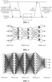
- FIG. 2 shows a schematic diagram of a basic structure of a simple neural network model.
- the network neural model includes: an input layer, a hidden layer and an output layer.
- the input layer is configured to receive data
- the hidden layer is configured to process the data
- the output layer is configured to generate a computed result of the neural network model.
- FIG. 3 shows a schematic diagram of a basic structure of a deep neural network model.
- the deep neural network model includes multiple hidden layers.
- the deep neural network model including multiple hidden layers can greatly improve the data processing capability, and is widely applied in the aspects such as pattern recognition, signal processing, optimization combination and anomaly detection.
- FIG. 4 shows a schematic structural diagram of a convolutional neural network model, which may include: an input layer, at least one convolutional layer, at least one pooling layer, a fully connected layer, and an output layer.
- the introduction of the convolutional layer and the pooling layer can effectively control the sharp increase in the number of network parameters, which limits the number of network parameters, and mines the characteristics of the local structure, and therefore improves the robustness of a convolutional neural network algorithm.
- the basic principle of the current wireless communication system is completed based on theoretical modeling and parameter selection of the actual communication environment.
- the gain brought by a working manner of the wireless communication system based on a classical model theory is gradually weaken.
- a new wireless communication manner shall be found and adopted.
- One implementation mode is that CSI feedback is performed using a neural network model.
- One advantage of performing CSI feedback using the neural network model is that the information after feedback is complete channel information instead of processed channel information, which is beneficial for the communication system to better utilize the channel information and the current channel state for data transmission.
- FIG. 5 shows a schematic diagram of performing CSI feedback using a neural network model.
- a terminal device generates first channel information from original channel information through the neural network model at the encoding end, and the neural network model at the decoding end generates feedback channel information from the first channel information through a decoding sub-model.
- a method of performing CSI indication and channel quality information restoration based on a neural network model is a good attempt, but the applicant found the following problems when CSI indication and restoration of channel quality information restoration is performed based on the neural network model.
- First, for a certain type of a channel it is more effective to construct an encoding network model and a decoding network model using a neural network model, so as to implement CSI indication and channel quality information restoration.
- the channel situation in the real physical world is complex and affected by the environment.
- the channel situation in the real physical world is time-varying, so that it is difficult to effectively deal with the time-varying characteristics of the channel by using a specific neural network model to implement the encoding network model and the decoding network model.
- the above problems may also exist, that is, (1) the channel indication and restoration effect is poor, (2) the neural network model is complex, and (3) the indication overhead required to indicate the CSI is relatively large, and the requirement for the air interface transmission resources is relatively large.
- some models are effective for the channel(s) in a scenario A, but fail directly for the channel(s) in a scenario B. Some models change with the time of the channel in the same scenario and have unstable performance for CSI indication and channel quality information restoration.
- GSM Global System for Mobile Communications
- CDMA Code Division Multiple Access
- WCDMA Wideband Code Division Multiple Access
- GPRS General Packet Radio Service
- LTE Long Term Evolution
- FDD Frequency Division Duplex
- TDD Time Division Duplex
- LTE-A Advanced Long Term Evolution
- NR Universal Mobile Telecommunications System
- WiMAX Worldwide Interoperability for Microwave Access
- WLAN Wireless Local Area Network
- WiFi Wireless Fidelity
- the network device involved in the embodiments of the present application may be a common base station (such as NodeB or Evolutional Node B (eNB) or gNB), a NR controller, a centralized unit, a NR base station, a remote radio frequency module, a micro base station, a relay, a distributed unit, a Transmission Reception Point (TRP), a Transmission Point (TP) or any other devices.
- No limits are made to specific technologies and specific device forms adopted by the network device in the embodiments of the present application.
- the above apparatuses providing a wireless communication function for the terminal device are collectively referred to a network device.
- the terminal device may be any terminal.
- the terminal device may be User Equipment (UE) in Machine Type Communication (MTC). That is to say, the terminal device may also be called the UE, a Mobile Station (MS), a mobile terminal, a terminal, etc.
- the terminal device may communicate with one or more core networks through a Radio Access Network (RAN).
- RAN Radio Access Network
- the terminal device may be a mobile terminal (or referred to as a "cellular" phone) and a computer with a mobile terminal.
- the terminal device may also be a portable, pocket-sized, hand-held, computer built-in, or in-vehicle mobile apparatus, which exchanges language and/or data with the RAN. No specific limits are made thereto in the embodiments of the present application.
- the network device and the terminal device may be deployed on land, including indoors or outdoors, and may be held in hands or deployed in vehicles, or may be deployed on water, or may be deployed on an aircraft, a balloon, and an artificial satellite in the air. No limits are made to the application scenario of the network device and the terminal device in the embodiments of the present application.
- communication may be performed between the network device and the terminal device and between the terminal devices through a licensed spectrum, or through an unlicensed spectrum, or through the licensed spectrum and the unlicensed spectrum simultaneously.
- Communication may be performed between the network device and the terminal device and between the terminal devices through a spectrum less than 7 gigahertz (GHz), or through a spectrum greater than 7 GHz, or through the spectra less than 7 GHz and greater than 7 GHz simultaneously. No limits are made to the spectrum resource used between the network device and the terminal device in the embodiments of the present application.
- D2D Device to Device
- M2M Machine to Machine
- MTC Vehicle to Vehicle
- V2V Vehicle to Vehicle
- the embodiments of the present application may also be applied to these communication systems.
- FIG. 6 shows a communication system 100 applied in embodiments of the present application.
- the communication system 100 may include a network device 110, and the network device 110 may be a device communicating with a terminal device 120 (or called a communication terminal, or a terminal).
- the network device 110 may provide communication coverage for a specific geographical region and may communicate with a terminal device located in the coverage.
- the network device 110 may be a Base Transceiver Station (BTS) in the GSM or the CDMA system, or may also be a NB in the WCDMA system, or may also be an eNB or eNodeB in the LTE system or a wireless controller in a Cloud Radio Access Network (CRAN).
- BTS Base Transceiver Station
- the network device may be a mobile switching center, a relay station, an access point, a vehicle device, a wearable device, a hub, a switch, a network bridge, a router, a network-side device in a 5G network, a network device in a future evolved Public Land Mobile Network (PLMN) or the like.
- PLMN Public Land Mobile Network
- the communication system 100 further includes at least one terminal device 120 within the coverage of the network device 110.
- a "terminal device” used herein includes, but is not limited to, a device arranged to receive/send a communication signal through a wired line connection, for example, through Public Switched Telephone Network (PSTN), Digital Subscriber Line (DSL), digital cable and direct cable connections; and/or another data connection/network); and/or through a wireless interface, for example, for a cellular network, a WLAN, a digital television network like a Digital Video Broadcasting-Handheld (DVB-H) network, a satellite network and an Amplitude Modulated (AM)-Frequency Modulated (FM) broadcast transmitter; and/or apparatuses, arranged to receive/send the communication signal, of another terminal device; and/or an Internet of Things (IoT) device.
- PSTN Public Switched Telephone Network
- DSL Digital Subscriber Line
- FM Digital Cable and direct cable connections
- another data connection/network and/or through
- the terminal device arranged to communicate through a wireless interface may be called a "wireless communication terminal", a “wireless terminal” or a “mobile terminal.”
- a mobile terminal include, but is not limited to, a satellite or cellular telephone, a Personal Communication System (PCS) terminal that is capable of combining a cellular radio telephone and data processing, faxing and data communication capabilities; a Personal Digital Assistant (PDA) that is capable of including a radio telephone, a pager, Internet/intranet access, a Web browser, a notepad, a calendar and/or a Global Positioning System (GPS) receiver; and a conventional laptop and/or palmtop receiver or another electronic device including a radio telephone transceiver.
- PCS Personal Communication System
- PDA Personal Digital Assistant
- GPS Global Positioning System
- the terminal device may refer to an access terminal, UE, a user unit, a user station, a mobile station, a mobile radio station, a remote station, a remote terminal, a mobile device, a user terminal, a terminal, a wireless communication device, a user agent or a user device.
- the access terminal may be a cell phone, a cordless phone, a Session Initiation Protocol (SIP) phone, a Wireless Local Loop (WLL) station, a PDA, a handheld device with a wireless communication function, a computing device, another processing device connected to a wireless modem, an on-board device, a wearable device, a terminal device in the 5G network, a terminal device in the future evolved PLMN or the like.
- SIP Session Initiation Protocol
- WLL Wireless Local Loop
- D2D communication may be performed between the terminal devices 120.
- the 5G system or the 5G network may also be called an NR system or an NR network.
- FIG. 6 exemplarily shows a network device and two terminal devices.
- the communication system 100 may include multiple network devices and another number of terminal devices may be included in coverage of each network device. There are no limits made thereto in the embodiments of the present application.
- the communication system 100 may further include other network entities such as a network controller and a mobility management entity. There are no limits made thereto in the embodiments of the present application.
- a device with a communication function in the network/system in the embodiments of the present application may be called a communication device.
- the communication device may include the network device 110 and terminal device 120 with the communication function.
- the network device 110 and the terminal device 120 may be the specific devices mentioned above and will not be elaborated herein.
- the communication device may further include other devices in the communication system 100, for example, other network entities such as a network controller and a mobility management entity. There are no limits made thereto in the embodiments of the present application.
- FIG. 7 shows an optional processing flow of a method for processing CSI provided by an embodiment of the present application. As shown in FIG. 7 , the method includes the following operations.
- a first device determines a channel type of a channel.
- the first device may be a terminal device.
- the terminal device may be a terminal device in a traditional communication network, or a terminal device in D2D communication, or a terminal device in Vehicle to X (V2X) communication.
- the first device may also be a network device.
- the first device determines channel state indication information of the channel based on a first determination manner corresponding to the channel type.
- the method may further include the following operations.
- the first device sends the channel state indication information and/or the channel type to a second device.
- the first device may send the channel state indication information and/or the channel type to the second device.
- the first device may send the channel state indication information and/or the channel type to the second device using at least one of the following: Uplink Control Link (UCI), a Physical Uplink Control Channel (PUCCH), a Physical Uplink Shared Channel (PUSCH), a Radio Resource Control (RRC) message, a message 1 (Msgl) in a four-step random access procedure, an Msg3 in the four-step random access procedure, or an MsgA in a two-step random access procedure.
- UCI Uplink Control Link
- PUCCH Physical Uplink Control Channel
- PUSCH Physical Uplink Shared Channel
- RRC Radio Resource Control
- the first device may send a channel type identifier corresponding to the channel type and first identification information corresponding to the first determination manner to the second device, to notify the second device the channel type and the channel state indication information.
- the first device may periodically send the channel type to the second device. For example, the first device sends the channel type to the second device in a first period.
- the first period may be sent to the first device by the second device through first indication information.
- the first indication information includes at least one of the following: frequency domain resources for sending the channel type, the first period, or time within the first period.
- the first device may also send the channel type to the second device as required. For example, when the first device determines that the channel type of a current channel changes, the first device sends the channel type to the second device.
- the first device may send an indication that the channel type is updated to the second device through second indication information, and indicate the updated channel type.
- the first device may determine the channel type based on a second determination manner.
- the second determination manner may be a second neural network model or a second algorithm, etc.
- information of the channel may be used as input information of the second determination manner, and the output information of the second determination manner is the channel type.
- the second determination manner is the second neural network model
- the second neural network model is a neural network model obtained by training with different dimensions of channel characteristics of the channel as granularity, with the channel quality information of the channel as input, and with the channel type of the channel as output.
- the channel characteristics may include at least one of the following: frequency, time delay, a transmitting antenna, a transmitting port, a transmitting angle, a receiving antenna, a receiving port, or a receiving angle.
- the information of the channel may include quality information of the channel.
- the quality information of the channel includes at least one of the following: Reference Signal Received Power (RSRP), Reference Signal Received Quality (RSRQ), a Received Signal Strength Indicator (RSSI), or a Signal-to-Noise and Interference Ratio (SINR).
- RSRP Reference Signal Received Power
- RSRQ Reference Signal Received Quality
- RSSI Received Signal Strength Indicator
- SINR Signal-to-Noise and Interference Ratio
- the second neural network model may include at least one fully connected layer, a normalization layer, an activation function, a convolutional layer, and a pooling layer, and may also include a specific network structure, such as a recurrent neural network structure, a Long Short-Term Memory (LSTM) structure.
- LSTM Long Short-Term Memory
- the second determination manner may be predetermined in a protocol or configured by the second device.
- the second device sends the second determination manner to the first device through first information.
- the first information may include at least one of the following: downlink data information, a Non-Access Stratum (NAS) message, a broadcast message, a multicast message, a RRC message, a Media Access Control Control Element (MAC CE), or Downlink Control Information (DCI).
- each second determination manner may correspond to one piece of second identification information, and the second identification information may be sent to the first device.
- the second identification information corresponding to the second determination manner may be second identification information corresponding to the second neural network model, or second identification information corresponding to parameter information of the second algorithm.
- the second determination manner is valid under the first channel condition. That is, the second determination manner is valid under the channel environment conditions such as a certain time range and a space range.
- the second determination manner may be updated in at least one of the following manners, which will be described in detail below.
- an optional processing flow for updating the second determination manner includes the following operations.
- the first device updates the second determination manner.
- the first device updates the second determination manner in a case where the channel condition of the user changes significantly.
- the first device sends second information to the second device.
- the second information is configured to indicate the updated second determination manner.
- the first device updates the second determination manner, and notifies through the second information the second device that the second determination manner is updated. If the first device updates the second neural network model, the second algorithm, or the second model, etc. which is configured to determine the channel type, the first device sends the parameters of the updated second determination manner to a geothermal device through the second information. Alternatively, the first device sends the second identification information corresponding to the updated second determination manner to the second device.
- the second information may include at least one of the following: UCI, PUCCH, PUSCH, an RRC message, an Msg1 in a four-step random access procedure, an Msg3 in the four-step random access procedure, or an MsgA in the two-step random access procedure.
- the first device updates the second determination manner according to a request of the second device.
- another optional processing flow for updating the second determination manner includes the following operations.
- the second device sends third information to the first device.
- the third information is configured to request the first device to update the second determination manner.
- the second device in a case where the second device determines that the second determination manner needs to be updated, the second device requests the first device to update the second determination manner through the third information.
- the third information includes at least one of the following: Msg2 in the four-step random access procedure, Msg4 in the four-step random access procedure, MsgB in the two-step random access procedure, DCI, a Physical Downlink Control Channel (PDCCH), a Physical Downlink Shared Channel (PDSCH), RRC information, a multicast message, a broadcast message, or downlink data information.
- the first device updates the second determination manner.
- the first device updates the second determination manner according to the request of the second device.
- the first device sends second information to the second device.
- the second information is configured to indicate the updated second determination manner.
- the first device updates the second determination manner, and notifies through the second information the second device that the second determination manner is updated. If the first device has updated the second neural network model, the second algorithm, or the second model, etc. configured to determine the channel type, the first device sends the parameters of the updated second determination manner to a geothermal device through the second information. Alternatively, the first device sends the second identification information corresponding to the updated second determination manner to the second device.
- the second information may include at least one of the following: UCI, PUCCH, PUSCH, an RRC message, Msg1 in the four-step random access procedure, Msg3 in the four-step random access procedure, or MsgA in the two-step random access procedure.
- the second device actively updates the second determination manner.
- yet another optional processing flow for updating the second determination manner includes the following operations.
- the second device updates the second determination manner.
- the second device updates the second determination manner in a case where the channel condition of the user changes significantly.
- the second device sends fourth information to the second device.
- the fourth information is configured to indicate the updated second determination manner.
- the second device updates the second determination manner, and notifies through the fourth information the first device that the second determination manner is updated.
- the fourth information carries second identification information corresponding to the updated second determination manner; or, the fourth information carries parameters of the updated second determination manner.
- the fourth information includes at least one of the following: Msg2 in the four-step random access procedure, Msg4 in the four-step random access procedure, MsgB in a two-step random access procedure, DCI, PDCCH, PDSCH, RRC information, a multicast message, a broadcast message, or downlink data information.
- the second device updates the second determination manner according to the request of the first device.
- still another optional processing flow for updating the second determination manner includes the following operations.
- the first device sends fifth information to the second device.
- the fifth information is configured to request the second device to update the second determination manner.
- the first device in a case where the first device determines that the second determination manner needs to be updated, the first device requests the first device to update the second determination manner through the fifth information.
- the fifth information includes at least one of the following: PUCCH, PUSCH, an RRC message, Msg1 in a four-step random access procedure, Msg3 in the four-step random access procedure, or MsgA in a two-step random access procedure.
- the second device updates the second determination manner.
- the second device updates the second determination manner according to the request of the first device.
- the second device sends fourth information to the first device.
- the fourth information is configured to indicate the updated second determination manner.
- the second device updates the second determination manner, and notifies through the fourth information the first device that the second determination manner is updated.
- the fourth information carries second identification information corresponding to the updated second determination manner; or, the fourth information carries parameters of the updated second determination manner.
- the fourth information includes at least one of the following: Msg2 in the four-step random access procedure, Msg4 in the four-step random access procedure, MsgB in a two-step random access procedure, DCI, PDCCH, PDSCH, RRC information, a multicast message, a broadcast message, or downlink data information.
- multiple channel types may be preset, each channel type corresponds to one first determination manner, and the first determination manner is configured to determine channel state indication information of the channel.
- the channel state indication information is configured to indicate CSI.
- the first determination manner includes at least any one of the following: a first neural network model, a first encoding algorithm, and a first encoding model.
- each channel type corresponds to an encoding manner or an encoding neural network model.
- the first device determines that the channel type is the ninth type of channel, the first device encodes original channel information using a ninth encoding manner or a ninth neural network model matched with the ninth type of channel as the encoding neural network model, so as to obtain channel state indication information.
- the corresponding relationship between the channel types and the first determination manners may also be a many-to-one relationship.
- a group of channel types may adopt a corresponding first determination manner, such as a specific encoding neural network, an encoding algorithm, or an encoding model, to encode the original channel information, and the channel state indication information indicating the CSI is obtained after encoding.
- the first type to fifth type of channel correspond to an encoding manner 1
- the sixth type to tenth type of channel correspond to an encoding manner 2
- the eleventh type to fifteenth type of channel correspond to an encoding manner 3.
- the encoding manner adopted here may be an encoding neural network model.
- FIG. 13 shows another optional processing flow of a method for processing CSI provided by the embodiments of the present application. As shown in FIG. 13 , the method includes the following operations.
- a second device receives channel state indication information of a channel and third indication information.
- the third indication information is configured to indicate a third determination manner.
- the second device may receive the channel state indication information and the third indication information from a first device through at least one of the following: UCI, PUCCH, PUSCH, an RRC message, Msg1 in a four-step random access procedure, Msg3 in the four-step random access procedure, or MsgA in a two-step random access procedure.
- the second device may determine the third determination manner through a channel type identifier corresponding to the channel type carried in the third indication information or first identification information corresponding to the first determination manner.
- the second device may receive the third indication information through sixth information.
- the sixth information includes at least one of the following: the UCI, the PUCCH, the PUSCH, the RRC message, the Msg1 in the four-step random access procedure, the Msg3 in the four-step random access procedure, or the MsgA in the two-step random access procedure.
- the third indication information may carry identification information corresponding to the channel type of the channel.
- the second device may determine the third determination manner corresponding to the channel type according to the identification information corresponding to the channel type.
- the third indication information may also carry first identification information configured to determine the first determination manner of the channel state indication information, and the second device determines the channel type according to the first identification information.
- the third indication information carries identification information of an encoding neural network model configured to determine the channel state indication information, or the third indication information may also carry identification information of an encoding algorithm configured to determine the channel state indication information, or the third indication information may also carry identification information of an encoding model configured to determine the channel state indication information.
- the second device may determine the third determination manner according to the identification information carried in the third indication information. It may be understood that the third determination manner may be indicated by the identification information corresponding to the channel type, or may be indicated by the first identification information identifier of the first determination manner configured to determine the channel state indication information.
- the second device periodically receives the channel type sent by the first device.
- the second device receives the channel type from the first device in a first period.
- the first period may be sent to the first device by the second device through first indication information.
- the first indication information includes at least one of the following: frequency domain resources for sending the channel type, the first period, or the time within the first period.
- the first device may also send the channel type to the second device as required. For example, when the first device determines that the channel type of a current channel changes, the first device sends the channel type to the second device.
- the second device determines CSI corresponding to the information state indication information based on the third determination manner corresponding to the channel type.
- the third determination manner includes at least any one of the following: a third neural network model, a third decoding algorithm, and a third decoding model.
- the second device decodes the channel state indication information using the third neural network model, the third decoding algorithm or the third decoding model, to obtain the CSI.
- multiple channel types may be preset, each channel type corresponds to one third determination manner, and the third determination manner is configured to decode channel state indication information.
- the channel state indication information is configured to indicate CSI.
- each type of channel corresponds to a decoding manner or a decoding neural network model.
- the second device determines that the channel type is the ninth type of channel, the second device decodes the channel state indication information using a ninth decoding manner or a ninth neural network model matched with the ninth type of channel as the decoding neural network model, so as to obtain the CSI.
- the corresponding relationship between the channel types and the third determination manners may also be a many-to-one relationship.
- a group of channel types may adopt a corresponding third determination manner, such as a specific decoding neural network, a decoding algorithm, or a decoding model, to decode the channel state indication information, and the CSI is obtained after decoding.
- the first type to fifth type of channels correspond to a decoding manner 1
- the sixth type to tenth type of channels correspond to a decoding manner 2
- the eleventh type to fifteenth types of channels correspond to a decoding manner 3.
- the decoding manner adopted here may be a decoding neural network model.
- the method may further include the following operations.
- the second device receives second indication information.
- the second indication information is configured to indicate that the channel type is updated.
- the first device in a case where the first device updates the channel type, the first device sends the second indication information to the second device.
- the second indication information is configured to indicate that the channel type is updated and the updated channel type.
- the method may further include the following operations.
- the second device sends a second determination manner to the first device.
- the second determination manner is configured to determine the channel type by the first device.
- the second device sends the second determination manner to the first device through first information.
- the first information may include at least one of the following: downlink data information, NAS message, a broadcast message, the multicast message, an RRC message, MAC CE, or DCI.
- each second determination manner may correspond to one piece of second identification information, and the second identification information may be sent to the first device.
- the second identification information corresponding to the second determination manner may be second identification information corresponding to the second neural network model, or second identification information corresponding to parameter information of the second algorithm.
- the second determination manner is valid under the first channel condition. That is, the second determination manner is valid under the channel environment conditions such as a certain time range and a space range.
- the first device needs to determine the channel type using a more matched second determination manner, that is, the second determination manner is updated.
- the second determination manner may be updated by the manners shown in FIG. 9 to FIG. 12 in the embodiments of the present application, which will not be repeated here.
- the second device may be a network device, and the first device may also be a terminal device.
- the terminal device may be a terminal device in a traditional communication network, a terminal device in D2D communication, or a terminal device in V2X communication.
- FIG. 14 shows a detailed processing flow of a method for processing provided by an embodiment of the present application.
- Original channel information is input into a channel type determining unit of a first device to determine a current channel type. For example, there are Y types of channels, and the channel type determining unit determines that the original channel information belongs to the X-th type of channel.
- the channel type information is input into an encoding unit of the first device, and the encoding unit adopts an encoding manner corresponding to the channel type information, such as a specific coding neural network, an encoding algorithm, or an encoding model, to encode the original channel information, and channel state indication information configured to indicate the CSI is obtained after encoding.
- the first device outputs the channel state indication information to a decoding unit of the second device, and outputs the channel type information to a decoding unit of the second device.
- the decoding unit adopts a decoding manner corresponding to the channel type information, such as a specific decoding neural network, a decoding algorithm, or a decoding model, to decode the channel state indication information, and the CSI is obtained after decoding.
- the second neural network model is a neural network model obtained by training with different dimensions of channel characteristics of the channel as the granularity, channel quality information of the channel as the input, and the channel type of the channel as the output.
- the channel characteristics include at least one of the following: frequency, time delay, a transmitting antenna, a transmitting port, a transmitting angle, a receiving antenna, a receiving port, or a receiving angle.
- the channel quality information includes at least one of the following: the RSRP, the RSRQ, the RSSI, or the SINR.
- the second device trains the second neural network model with at least one of the frequency, the time delay, the transmitting antenna, the transmitting port, the transmitting angle, the receiving antenna, the receiving port, or the receiving angle as the granularity, and with at least one of the RSRP, the RSRQ, the RSSI, or the SINR as the input information, so that the second neural network model can predict the channel type.
- the communication between the first device and the second device may be implemented through a side link.
- the magnitude of a sequence number of the processes as described above does not mean an execution sequence, and the execution sequence of each process should be determined by its function and an internal logic and should not form any limit to an implementation process of the embodiments of the present application.
- a current channel type is determined by the second determination manner (such as the specific neural network model or the specific algorithm), the original channel information is encoded using the first determination manner matched with the determined channel type to obtain the channel state indication information, and the channel state indication information is decoded using the third determination manner matched with the determined channel type to obtain CSI.
- transmission of the CSI is performed based on the channel type, which can not only reduce the complexity of the first determination manner and the third determination manner, but also can improve the performance and utilization effect of the first determination manner and the third determination manner.
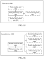
- FIG. 15 shows a composition structure of the first device.
- the first device 900 includes: a first processing unit 901.
- the first processing unit 901 is configured to determine a channel type of a channel, and determine channel state indication information of the channel based on a first determination manner corresponding to the channel type.
- the first processing unit 901 is configured to determine the channel type based on a second determination manner.
- the first processing unit 901 is configured to determine information of the channel as input information of the second determination manner, and use information output by the second determination manner as the channel type.
- the information of the channel includes: channel quality information of the channel.
- the second determination manner is predetermined in a protocol or configured by a second device.
- the second determination manner is sent to the first device by the second device through first information.
- the first information includes at least one of the following: downlink data information, a NAS message, a broadcast message, a multicast message, a RRC message, a MAC CE, or DCI.
- the first information carries second identification information corresponding to the second determination manner.
- the second determination manner is valid under a first channel condition.
- the first device 900 further includes: a second processing unit 902, configured to update the second determination manner.
- the second processing unit 902 is configured to send second information to the second device.
- the second information is configured to indicate the updated second determination manner.
- the second information carries second identification information corresponding to the updated second determination manner; or, the second information carries parameters of the updated second determination manner.
- the second information may include at least one of the following: UCI, a PUCCH, a PUSCH, an RRC message, an Msg1 in a four-step random access procedure, an Msg3 in the four-step random access procedure, or an MsgA in a two-step random access procedure.
- the first device 900 further includes: a first receiving unit 903, configured to receive third information sent by the second device.
- the third information is configured to request the first device to update the second determination manner.
- the third information includes at least one of the following: an Msg2 in the four-step random access procedure, an Msg4 in the four-step random access procedure, an MsgB in the two-step random access procedure, DCI, a PDCCH, a PDSCH, RRC information, a multicast message, a broadcast message, or downlink data information.
- the second processing unit 902 is configured to receive fourth information sent by the second device.
- the fourth information is configured to indicate the updated second determination manner.
- the fourth information carries second identification information corresponding to the updated second determination manner; or, the fourth information carries parameters of the updated second determination manner.
- the second processing unit 902 is configured to send fifth information to the second device.
- the fifth information is configured to request the second device to update the second determination manner.
- the fifth information includes at least one of the following: the PUCCH, the PUSCH, the RRC message, the Msg1 in the four-step random access procedure, the Msg3 in the four-step random access procedure, or the MsgA in the two-step random access procedure.
- the fourth information includes at least one of the following: the Msg2 in a four-step random access procedure, the Msg4 in the four-step random access procedure, the MsgB in a two-step random access procedure, the DCI, the PDCCH, the PDSCH, the RRC information, the multicast message, the broadcast message, or the downlink data information.
- the second determination manner includes at least any one of the following: a second neural network model and a second algorithm.
- the second neural network model is a neural network model obtained by training with different dimensions of channel characteristics of the channel as the granularity, channel quality information of the channel as input, and the channel type of the channel as output.
- the channel characteristics include at least one of the following: frequency, time delay, a transmitting antenna, a transmitting port, a transmitting angle, a receiving antenna, a receiving port, or a receiving angle.
- the channel quality information includes at least one of the following: RSRP, RSRQ, a RSSI or a SINR.
- the first device 900 further includes: a first sending unit 904, configured to send the channel state indication information and/or third indication information to the second device.
- the third indication information is configured to indicate a third determination manner for decoding the channel state indication information.
- the first processing unit 901 is configured to send the third indication information through sixth information.
- the sixth information includes at least one of the following: the UCI, the PUCCH, the PUSCH, the RRC message, the Msg1 in the four-step random access procedure, the Msg3 in the four-step random access procedure, or the MsgA in the two-step random access procedure.
- the third indication information carries identification information corresponding to the channel type of the channel; or, the third indication information carries information of the first determination manner.
- the information of the first determination manner includes: first identification information corresponding to the first determination manner.
- the first sending unit 904 is configured to send the channel type in a first period.
- the first processing unit 901 is further configured to receive first indication information sent by the second device.
- the first indication information is configured to indicate the first period in which the first device sends the channel type.
- the first indication information includes at least one of the following: frequency domain resources for sending the channel type, the first period, or time within the first period.
- the second processing unit 902 is further configured to send second indication information to the second device.
- the second indication information is configured to indicate that the channel type is updated.
- the first determination manner corresponds to at least one channel type.
- the first determination manner includes at least any one of the following: a first neural network model, a first encoding algorithm, and a first encoding model.
- the first device includes a terminal device or a network device; and/or the second device includes a network device or a terminal device.
- FIG. 16 shows a schematic structural diagram of an optional composition structure of the second device 1000.
- the second device includes: a second receiving unit 1001 and a third processing unit 1002.
- the second receiving unit 1001 is configured to receive channel state indication information of a channel and third indication information.
- the third indication information is configured to indicate a third determination manner.
- the third processing unit 1002 is configured to determine CSI corresponding to the information state indication information based on the third determination manner.
- the second receiving unit 1001 is configured to receive the third indication information through sixth information.
- the sixth information includes at least one of the following: UCI, a PUCCH, a PUSCH, an RRC message, an Msg1 in a four-step random access procedure, an Msg3 in the four-step random access procedure, and an MsgA in the two-step random access procedure.
- the third indication information carries identification information corresponding to a channel type of the channel; or, the third indication information carries information of a first determination manner configured to determine the channel state indication information.
- information of the first determination manner includes: first identification information corresponding to the first determination manner.
- a third receiving unit is configured to receive the channel type in a first period.
- the second device 1000 further includes: a second sending unit 1003.
- the second sending unit 1003 is configured to send first indication information to the first device.
- the first indication information is configured to indicate the first period in which the first device sends the channel type.
- the first indication information includes at least one of the following: frequency domain resources for sending the channel type, a first period, or time within the first period.
- the second receiving unit 1001 is further configured to receive second indication information.
- the second indication information is configured to indicate that the channel type is updated.
- the second device further includes: a third sending unit 1004.
- the third sending unit 1004 is configured to send a second determination manner to the first device.
- the second determination manner is used to determine the channel type by the first device.
- the third sending unit 1004 is configured to send the second determination manner through first information.
- the first information includes at least one of the following: downlink data information, a NAS message, a broadcast message, a multicast message, a RRC message, a MAC CE, or DCI.
- the first information carries second identification information corresponding to the second determination manner.
- the second determination manner is valid under a first channel condition.
- the second receiving unit 1001 is further configured to receive second information.
- the second information is configured to indicate an updated second determination manner for determining the channel type.
- the second information carries second identification information corresponding to the updated second determination manner; or, the second information carries parameters of the updated second determination manner.
- the second information includes at least one of the following: UCI, a PUCCH, a PUSCH, an RRC message, an Msg1 in a four-step random access procedure, an Msg3 in the four-step random access procedure, or an MsgA in a two-step random access procedure.
- the second device 1000 further includes: a fourth sending unit 1005.
- the fourth sending unit 1005 is configured to send third information to the first device.
- the third information is configured to request the first device to update the second determination manner.
- the third information includes at least one of the following: an Msg2 in the four-step random access procedure, an Msg4 in the four-step random access procedure, an MsgB in the two-step random access procedure, the DCI, a PDCCH, a PDSCH, RRC information, the multicast message, the broadcast message, or the downlink data information.
- the third processing unit 1002 is configured to update the second determination manner.
- the second device 1000 further includes: a fifth sending unit 1006.
- the fifth sending unit 1006 is configured to send fourth information to the first device.
- the fourth information is configured to indicate the updated second determination manner.
- the second receiving unit 1001 is further configured to receive fifth information.
- the fifth information is configured to request the second device to update the second determination manner.
- the fifth information includes at least one of the following: the PUCCH, the PUSCH, the RRC message, the Msg1 in the four-step random access procedure, the Msg3 in the four-step random access procedure, or the MsgA in the two-step random access procedure.
- the fourth information includes at least one of the following: the Msg2 in a four-step random access procedure, the Msg4 in the four-step random access procedure, the MsgB in a two-step random access procedure, the DCI, the PDCCH, the PDSCH, RRC information, the multicast message, the broadcast message, or the downlink data information.
- the second determination manner includes at least any one of the following: a second neural network model and a second algorithm.
- the third processing unit is configured to train the second neural network model by using different dimensions of channel characteristics of the channel as granularity, channel quality information of the channel as input, and the channel type of the channel as output.
- the channel characteristics include at least one of the following: frequency, time delay, a transmitting antenna, a transmitting port, a transmitting angle, a receiving antenna, a receiving port, or a receiving angle.
- the quality information of the channel includes at least one of the following: RSRP, RSRQ, RSSI or SINR.
- the third determination manner includes at least any one of the following: a third neural network model, a third decoding algorithm, and a third decoding model.
- the first device includes a terminal device or a network device; and/or the second device includes a network device or a terminal device.
- the embodiments of the present application further provide a first device, which includes: a processor and a memory configured to store a computer program capable of running on the processor.
- the processor is configured to perform, when executing the computer program, the steps of the method for processing CSI executed by the first device as described above.
- the embodiments of the present application further provide a second device, which includes: a processor and a memory configured to store a computer program capable of running on the processor.
- the processor is configured to perform, when executing the computer program, the steps of the method for processing CSI executed by the second device as described above.
- the embodiments of the present application further provide a chip, which includes: a processor, configured to call from a memory and run a computer program to enable a device installed with the chip to perform the method for processing CSI executed by the first device as described above.
- the embodiments of the present application provide a chip, which includes: a processor, configured to call from a memory and run a computer program to enable a device installed with the chip to perform the method for processing CSI executed by the above second device as described above.
- the embodiments of the present application further provide a storage medium, storing an executable program that, when executed by a processor, implements the method for processing CSI executed by the first device as described above.
- the embodiments of the present application further provide a storage medium, storing an executable program that, when executed by a processor, implements the method for processing CSI executed by the second device as described above.
- the embodiments of the present application further provide a computer program product, which includes: a computer program instruction.
- the computer program instruction enables a computer to perform the method for processing CSI executed by the first device as described above.
- the embodiments of the present application further provide a computer program product, which includes: a computer program instruction.
- the computer program instruction enables a computer to perform the method for processing CSI executed by the second device as described above.
- the embodiments of the present application further provide a computer program, enabling a computer to perform the method for processing CSI executed by the first device as described above.
- the embodiments of the present application further provide a computer program, enabling a computer to perform the method for processing CSI executed by the second device as described above.
- FIG. 17 is a schematic structural diagram of hardware compositions of an electronic device (second device or first device) of an embodiment of the present application.
- the terminal device 700 includes: at least one processor 701, a memory 702 and at least one network interface 704.
- Various components of the terminal device 700 are coupled together through a bus system 705.
- the bus system 705 is configured to implement connection and communication between these components.
- the bus system 705 further includes a power bus, a control bus, and a status signal bus.
- various buses are marked as the bus system 705 in FIG. 17 .
- the memory 702 may be a volatile memory or a non-volatile memory, or may include both a volatile memory and a non-volatile memory.
- the non-volatile memory may be a Read Only Memory (ROM), a Programmable Read-Only Memory (PROM), an Erasable Programmable Read-Only Memory (EPROM), an Electrically Erasable Programmable Read-Only Memory (EEPROM), a Ferromagnetic Random Access Memory (FRAM), a Flash Memory, a magnetic surface memory, an optical disk or a Compact Disc Read-Only Memory (CD-ROM); and the magnetic surface memory may be a magnetic disk memory or a magnetic tape memory.
- the volatile memory may be a RAM that acts as an external cache.
- RAM Random Access Memory
- SRAM Static Random Access Memory
- SSRAM Synchronous Static Random Access Memory
- DRAM Dynamic Random Access Memory
- SDRAM Synchronous Dynamic Random Access Memory
- DDRSDRAM Double Data Rate Synchronous Dynamic Random Access Memory
- ESDRAM Enhanced Synchronous Dynamic Random Access Memory
- SLDRAM SyncLink Dynamic Random Access Memory
- DRRAM Direct Rambus Random Access Memory
- the memory 702 described in the embodiment of the present application is intended to include, but is not limited to, these and any other suitable types of memories.
- the memory 702 in the embodiment of the present application is configured to store various types of data to support operation of the electronic device 700.
- Examples of such data include: any computer application operated on the electronic device 700, such as an application program 7022.
- a program for implementing the method in the embodiment of the present application may be included in the application program 7022.
- the method disclosed in the above embodiments of the present application may be applied to the processor 701, or may be implemented by the processor 701.
- the processor 701 may be an integrated circuit chip with signal processing capability. During implementation, the steps of the above method may be completed by hardware integrated logic circuits in the processor 701 or instructions in the form of software.
- the above processor 701 may be a general-purpose processor, a Digital Signal Processor (DSP), or other programmable logic devices, discrete gate or transistor logic devices, discrete hardware components, or the like.
- DSP Digital Signal Processor
- the processor 701 may implement or perform various methods, steps, and logical block diagrams disclosed in the embodiments of the present application.
- the general-purpose processor may be a microprocessor, or any conventional processor.
- Steps of the methods disclosed with reference to the embodiments of the present application may be directly performed and accomplished by a hardware decoding processor, or may be performed and accomplished by a combination of hardware and software modules in the decoding processor.
- a software module may be located in a storage medium. The storage medium is located in the memory 702, and the processor 701 reads information in the memory 702 and completes the steps of the above method in combination with hardware thereof.
- the electronic device 700 may be implemented by one or more Application Specific Integrated Circuits (ASICs), DSPs, Programmable Logic Devices (PLDs), Complex Programmable Logic Devices (CPLDs), FPGAs, general-purpose processors, controllers, MCUs, MPUs, or other electronic elements for executing the above methods.
- ASICs Application Specific Integrated Circuits
- DSPs Digital Signal processors
- PLDs Programmable Logic Devices
- CPLDs Complex Programmable Logic Devices
- FPGAs general-purpose processors
- controllers MCUs, MPUs, or other electronic elements for executing the above methods.
- These computer program instructions may be provided for a general-purpose computer, a dedicated computer, an embedded processor or processors of other programmable data processing devices to generate a machine, so that an apparatus for achieving functions designated in one or more flows of the flowcharts and/or one or more blocks of the block diagrams is generated via instructions executed by the computers or the processors of the other programmable data processing devices.
- These computer program instructions may also be stored in a computer readable memory capable of guiding the computers or the other programmable data processing devices to work in a specific mode, so that a manufactured product including an instruction apparatus is generated via the instructions stored in the computer readable memory, and the instruction apparatus achieves the functions designated in one or more flows of the flowcharts and/or one or more blocks of the block diagrams.
- These computer program instructions may also be loaded to the computers or the other programmable data processing devices, so that a series of operation steps are performed on the computers or the other programmable devices to generate processing implemented by the computers, and therefore the instructions executed on the computers or the other programmable devices provide a step of achieving the functions designated in one or more flows of the flowcharts and/or one or more blocks of the block diagrams.
- system and “network” in the present application are often used interchangeably herein.
- the term “and/or” in this application describes only an association relationship for describing associated objects and represents that three relationships may exist. For example, A and/or B may represent the following three cases: Only A exists, both A and B exist, and only B exists.
- the character "/" in the present application generally indicates an "or" relationship between the associated objects.
Landscapes
- Engineering & Computer Science (AREA)
- Computer Networks & Wireless Communication (AREA)
- Signal Processing (AREA)
- Quality & Reliability (AREA)
- Mobile Radio Communication Systems (AREA)
Applications Claiming Priority (1)
| Application Number | Priority Date | Filing Date | Title |
|---|---|---|---|
| PCT/CN2020/093465 WO2021237715A1 (fr) | 2020-05-29 | 2020-05-29 | Procédé de traitement d'informations d'état de canal, dispositif électronique, et support de stockage |
Publications (2)
| Publication Number | Publication Date |
|---|---|
| EP4152803A1 true EP4152803A1 (fr) | 2023-03-22 |
| EP4152803A4 EP4152803A4 (fr) | 2023-06-14 |
Family
ID=78745474
Family Applications (1)
| Application Number | Title | Priority Date | Filing Date |
|---|---|---|---|
| EP20937984.1A Pending EP4152803A4 (fr) | 2020-05-29 | 2020-05-29 | Procédé de traitement d'informations d'état de canal, dispositif électronique, et support de stockage |
Country Status (4)
| Country | Link |
|---|---|
| US (1) | US12470967B2 (fr) |
| EP (1) | EP4152803A4 (fr) |
| CN (1) | CN115669047A (fr) |
| WO (1) | WO2021237715A1 (fr) |
Cited By (2)
| Publication number | Priority date | Publication date | Assignee | Title |
|---|---|---|---|---|
| WO2024154113A1 (fr) * | 2023-02-21 | 2024-07-25 | Lenovo (Singapore) Pte. Ltd. | Sélection de modèle d'apprentissage automatique dans des systèmes de communication sans fil |
| EP4507222A1 (fr) * | 2023-08-08 | 2025-02-12 | Nokia Solutions and Networks Oy | Optimisation d'une forme d'onde pour des conditions de canal |
Families Citing this family (6)
| Publication number | Priority date | Publication date | Assignee | Title |
|---|---|---|---|---|
| CN116828498A (zh) * | 2022-03-21 | 2023-09-29 | 维沃移动通信有限公司 | 信道特征信息上报及恢复方法、终端和网络侧设备 |
| CN117280723A (zh) * | 2022-03-31 | 2023-12-22 | 北京小米移动软件有限公司 | 基于ai的csi处理能力确定方法、装置、介质、产品及芯片 |
| CN116938296A (zh) * | 2022-04-08 | 2023-10-24 | 大唐移动通信设备有限公司 | Csi处理方法、装置、设备及存储介质 |
| CN117715075A (zh) * | 2022-09-15 | 2024-03-15 | 维沃移动通信有限公司 | Cqi传输方法、装置、终端及网络侧设备 |
| EP4472091A1 (fr) * | 2023-05-19 | 2024-12-04 | Nokia Technologies Oy | Rapport de sinr différencié de démodulation pour rapport de mesure basé sur un groupe mtrp |
| CN120263861A (zh) * | 2024-01-04 | 2025-07-04 | 维沃移动通信有限公司 | 一种基于ai的csi压缩方法、装置、终端及网络侧设备 |
Family Cites Families (9)
| Publication number | Priority date | Publication date | Assignee | Title |
|---|---|---|---|---|
| CN103503332B (zh) * | 2011-05-04 | 2016-05-18 | Lg电子株式会社 | 在无线通信系统中发射/接收信道状态信息的方法和装置 |
| US9713165B2 (en) * | 2012-05-11 | 2017-07-18 | Telefonaktiebolaget Lm Ericsson (Publ) | Scheduling a user equipment in a communication system |
| CN102694624B (zh) * | 2012-05-28 | 2015-12-02 | 清华大学 | 自适应编码调制方法及装置 |
| JP2019145857A (ja) * | 2016-06-28 | 2019-08-29 | シャープ株式会社 | 端末装置、基地局装置、通信方法、および、集積回路 |
| CN107707285B (zh) * | 2016-08-05 | 2021-04-09 | 华为技术有限公司 | 信道状态信息的发送方法、接收方法以及装置 |
| US10382230B2 (en) * | 2017-03-31 | 2019-08-13 | Mitsubishi Electric Research Laboratories, Inc. | System and method for channel estimation in mmWave communications exploiting joint AoD-AoA angular spread |
| CN111869291B (zh) * | 2018-02-02 | 2025-05-09 | 康奈尔大学 | 无线系统中的信道制图 |
| CN109150775B (zh) * | 2018-08-14 | 2020-03-17 | 西安交通大学 | 自适应噪声环境动态变化的鲁棒性在线信道状态估计方法 |
| CN109316192B (zh) * | 2018-09-13 | 2020-07-17 | 清华大学 | 基于移动网络信道状态信息的坐姿检测方法及装置 |
-
2020
- 2020-05-29 WO PCT/CN2020/093465 patent/WO2021237715A1/fr not_active Ceased
- 2020-05-29 CN CN202080101235.3A patent/CN115669047A/zh active Pending
- 2020-05-29 EP EP20937984.1A patent/EP4152803A4/fr active Pending
-
2022
- 2022-11-29 US US18/071,195 patent/US12470967B2/en active Active
Cited By (2)
| Publication number | Priority date | Publication date | Assignee | Title |
|---|---|---|---|---|
| WO2024154113A1 (fr) * | 2023-02-21 | 2024-07-25 | Lenovo (Singapore) Pte. Ltd. | Sélection de modèle d'apprentissage automatique dans des systèmes de communication sans fil |
| EP4507222A1 (fr) * | 2023-08-08 | 2025-02-12 | Nokia Solutions and Networks Oy | Optimisation d'une forme d'onde pour des conditions de canal |
Also Published As
| Publication number | Publication date |
|---|---|
| CN115669047A (zh) | 2023-01-31 |
| WO2021237715A1 (fr) | 2021-12-02 |
| US12470967B2 (en) | 2025-11-11 |
| US20230085850A1 (en) | 2023-03-23 |
| EP4152803A4 (fr) | 2023-06-14 |
Similar Documents
| Publication | Publication Date | Title |
|---|---|---|
| US12470967B2 (en) | Channel state information processing method, electronic device, and storage medium | |
| US20240291692A1 (en) | Uplink transmission instruction method, terminal, base station and computer storage medium | |
| RU2711033C1 (ru) | Способы и устройства обеспечения покрытия лучом устройства связи, работающего в сети беспроводной связи | |
| US12127235B2 (en) | Method for processing CSI, terminal device, and network device | |
| JP2023517032A (ja) | ネットワーク装置、端末装置、及び方法 | |
| CN115280338A (zh) | 一种基于联邦学习的模型训练方法、电子设备及存储介质 | |
| WO2022205071A1 (fr) | Établissement de rapport d'informations d'état de canal pour opération à multiples points d'émission-réception | |
| US20230012043A1 (en) | Machine learning model training method, electronic device and storage medium | |
| CN118302964A (zh) | 基于人工智能的信道状态信息框架 | |
| CN110838861B (zh) | 信号传输方法、波束确定方法及其装置 | |
| US20260006479A1 (en) | Data transmission method, electronic device, and storage medium | |
| CN117616714A (zh) | Csi反馈方案的更新方法、装置、设备及存储介质 | |
| WO2023150929A1 (fr) | Sélection de faisceau assistée par apprentissage automatique | |
| WO2021035492A1 (fr) | Procédés de traitement d'informations d'état de canal, dispositif électronique et support d'informations | |
| WO2024149042A1 (fr) | Procédé de communication et appareil de communication | |
| US20250317182A1 (en) | Wireless communication method, terminal device, and network device | |
| CN118158732A (zh) | 非周期cli汇报方法及装置、计算机可读存储介质 | |
| WO2022253150A1 (fr) | Procédé et appareil de transmission de données | |
| WO2022041284A1 (fr) | Procédé et appareil de communication | |
| WO2025199915A1 (fr) | Procédé et appareil pour déterminer des faisceaux prédits à rapporter | |
| US20260067045A1 (en) | Channel State Information Measurement Method and Communication Apparatus | |
| WO2025171501A1 (fr) | Dispositifs et procédés de communication | |
| US20240040576A1 (en) | Mapping Unified Transmission States for Multipoint Control Channel Reception Using Rules | |
| CN120238888A (zh) | 监控方法与装置、终端设备和网络设备 | |
| CN121771777A (zh) | 一种通信方法和相关设备 |
Legal Events
| Date | Code | Title | Description |
|---|---|---|---|
| STAA | Information on the status of an ep patent application or granted ep patent |
Free format text: STATUS: THE INTERNATIONAL PUBLICATION HAS BEEN MADE |
|
| PUAI | Public reference made under article 153(3) epc to a published international application that has entered the european phase |
Free format text: ORIGINAL CODE: 0009012 |
|
| STAA | Information on the status of an ep patent application or granted ep patent |
Free format text: STATUS: REQUEST FOR EXAMINATION WAS MADE |
|
| 17P | Request for examination filed |
Effective date: 20221216 |
|
| AK | Designated contracting states |
Kind code of ref document: A1 Designated state(s): AL AT BE BG CH CY CZ DE DK EE ES FI FR GB GR HR HU IE IS IT LI LT LU LV MC MK MT NL NO PL PT RO RS SE SI SK SM TR |
|
| A4 | Supplementary search report drawn up and despatched |
Effective date: 20230515 |
|
| RIC1 | Information provided on ipc code assigned before grant |
Ipc: H04B 7/06 20060101ALI20230509BHEP Ipc: H04W 24/10 20090101AFI20230509BHEP |
|
| DAV | Request for validation of the european patent (deleted) | ||
| DAX | Request for extension of the european patent (deleted) | ||
| STAA | Information on the status of an ep patent application or granted ep patent |
Free format text: STATUS: EXAMINATION IS IN PROGRESS |
|
| 17Q | First examination report despatched |
Effective date: 20260227 |