EP4153041B1 - Système et procédés de détection et d'élimination de bruit électrique dans des électrodes sèches - Google Patents
Système et procédés de détection et d'élimination de bruit électrique dans des électrodes sèches Download PDFInfo
- Publication number
- EP4153041B1 EP4153041B1 EP21762831.2A EP21762831A EP4153041B1 EP 4153041 B1 EP4153041 B1 EP 4153041B1 EP 21762831 A EP21762831 A EP 21762831A EP 4153041 B1 EP4153041 B1 EP 4153041B1
- Authority
- EP
- European Patent Office
- Prior art keywords
- signal
- user
- computing device
- user computing
- noise
- Prior art date
- Legal status (The legal status is an assumption and is not a legal conclusion. Google has not performed a legal analysis and makes no representation as to the accuracy of the status listed.)
- Active
Links
Images





Classifications
-
- A—HUMAN NECESSITIES
- A61—MEDICAL OR VETERINARY SCIENCE; HYGIENE
- A61B—DIAGNOSIS; SURGERY; IDENTIFICATION
- A61B5/00—Measuring for diagnostic purposes; Identification of persons
- A61B5/02—Detecting, measuring or recording for evaluating the cardiovascular system, e.g. pulse, heart rate, blood pressure or blood flow
- A61B5/0205—Simultaneously evaluating both cardiovascular conditions and different types of body conditions, e.g. heart and respiratory condition
-
- A—HUMAN NECESSITIES
- A61—MEDICAL OR VETERINARY SCIENCE; HYGIENE
- A61B—DIAGNOSIS; SURGERY; IDENTIFICATION
- A61B5/00—Measuring for diagnostic purposes; Identification of persons
- A61B5/05—Detecting, measuring or recording for diagnosis by means of electric currents or magnetic fields; Measuring using microwaves or radio waves
- A61B5/053—Measuring electrical impedance or conductance of a portion of the body
- A61B5/0531—Measuring skin impedance
-
- A—HUMAN NECESSITIES
- A61—MEDICAL OR VETERINARY SCIENCE; HYGIENE
- A61B—DIAGNOSIS; SURGERY; IDENTIFICATION
- A61B5/00—Measuring for diagnostic purposes; Identification of persons
- A61B5/103—Measuring devices for testing the shape, pattern, colour, size or movement of the body or parts thereof, for diagnostic purposes
- A61B5/11—Measuring movement of the entire body or parts thereof, e.g. head or hand tremor or mobility of a limb
- A61B5/1118—Determining activity level
-
- A—HUMAN NECESSITIES
- A61—MEDICAL OR VETERINARY SCIENCE; HYGIENE
- A61B—DIAGNOSIS; SURGERY; IDENTIFICATION
- A61B5/00—Measuring for diagnostic purposes; Identification of persons
- A61B5/68—Arrangements of detecting, measuring or recording means, e.g. sensors, in relation to patient
- A61B5/6801—Arrangements of detecting, measuring or recording means, e.g. sensors, in relation to patient specially adapted to be attached to or worn on the body surface
- A61B5/6802—Sensor mounted on worn items
- A61B5/681—Wristwatch-type devices
-
- A—HUMAN NECESSITIES
- A61—MEDICAL OR VETERINARY SCIENCE; HYGIENE
- A61B—DIAGNOSIS; SURGERY; IDENTIFICATION
- A61B5/00—Measuring for diagnostic purposes; Identification of persons
- A61B5/72—Signal processing specially adapted for physiological signals or for diagnostic purposes
- A61B5/7203—Signal processing specially adapted for physiological signals or for diagnostic purposes for noise prevention, reduction or removal
-
- A—HUMAN NECESSITIES
- A61—MEDICAL OR VETERINARY SCIENCE; HYGIENE
- A61B—DIAGNOSIS; SURGERY; IDENTIFICATION
- A61B5/00—Measuring for diagnostic purposes; Identification of persons
- A61B5/72—Signal processing specially adapted for physiological signals or for diagnostic purposes
- A61B5/7203—Signal processing specially adapted for physiological signals or for diagnostic purposes for noise prevention, reduction or removal
- A61B5/7207—Signal processing specially adapted for physiological signals or for diagnostic purposes for noise prevention, reduction or removal of noise induced by motion artifacts
- A61B5/7214—Signal processing specially adapted for physiological signals or for diagnostic purposes for noise prevention, reduction or removal of noise induced by motion artifacts using signal cancellation, e.g. based on input of two identical physiological sensors spaced apart, or based on two signals derived from the same sensor, for different optical wavelengths
-
- A—HUMAN NECESSITIES
- A61—MEDICAL OR VETERINARY SCIENCE; HYGIENE
- A61B—DIAGNOSIS; SURGERY; IDENTIFICATION
- A61B5/00—Measuring for diagnostic purposes; Identification of persons
- A61B5/74—Details of notification to user or communication with user or patient; User input means
- A61B5/742—Details of notification to user or communication with user or patient; User input means using visual displays
-
- A—HUMAN NECESSITIES
- A61—MEDICAL OR VETERINARY SCIENCE; HYGIENE
- A61B—DIAGNOSIS; SURGERY; IDENTIFICATION
- A61B2562/00—Details of sensors; Constructional details of sensor housings or probes; Accessories for sensors
- A61B2562/02—Details of sensors specially adapted for in-vivo measurements
- A61B2562/0247—Pressure sensors
-
- A—HUMAN NECESSITIES
- A61—MEDICAL OR VETERINARY SCIENCE; HYGIENE
- A61B—DIAGNOSIS; SURGERY; IDENTIFICATION
- A61B5/00—Measuring for diagnostic purposes; Identification of persons
- A61B5/24—Detecting, measuring or recording bioelectric or biomagnetic signals of the body or parts thereof
- A61B5/25—Bioelectric electrodes therefor
-
- A—HUMAN NECESSITIES
- A61—MEDICAL OR VETERINARY SCIENCE; HYGIENE
- A61B—DIAGNOSIS; SURGERY; IDENTIFICATION
- A61B5/00—Measuring for diagnostic purposes; Identification of persons
- A61B5/68—Arrangements of detecting, measuring or recording means, e.g. sensors, in relation to patient
- A61B5/6801—Arrangements of detecting, measuring or recording means, e.g. sensors, in relation to patient specially adapted to be attached to or worn on the body surface
- A61B5/6843—Monitoring or controlling sensor contact pressure
Definitions
- the present disclosure relates generally to noise reduction for signals in wearable computing systems.
- User computing devices have increased in processing power and utility.
- User computing devices can include wearable computing devices.
- One key use for wearable computing devices is measuring user information, such as heart rate, temperature, and so on. This information can be measured using an electrode in contact with the user's skin.
- no gel electrolyte can generally be used because of the potential inconvenience to users.
- the signal measured by the electrode can potentially have a significant amount of noise introduced that makes it difficult for the user computing device to accurately measure user information.
- Document CA 2 918 594 A1 discloses a physiological signal extractor comprising a motion artifact reduction unit that can be disposed in or attached to a wearable device.
- reference US 10 362 940 B2 describes using a differential amplifier in conjunction with an ECG electrode to cancel out noise.
- US 2016/000344 A1 discloses an implantable pressure sensor device for measuring a physiological signal comprising a reference capacitor positioned within the vicinity of a sensing capacitor in order to accurately cancel out noise signals or other artefacts.
- document WO 2014/163443 A1 discloses an electronic stethoscope apparatus having a noise removing part for removing sensed noised from sensed bioacoustics.
- the present disclosure is directed towards a system for mitigating the effect of signal noise on data captured by sensors included in a user computing device (e.g., such as a fitness band) in contact with skin.
- a user computing device e.g., such as a fitness band
- the user computing device includes a physiological signal sensor, such as a dry electrode (e.g., a single metal sensor) in contact with the skin that acts as a conductor between the skin and the user computing device.
- the dry electrode is the source of a first signal used by the user computing device in any one of a plurality of analysis algorithms.
- the first signal can represent a signal generated based on one or more physiological phenomenon.
- the user computing device also includes a transducer.
- the transducer can include any of a plurality of different sensor types (e.g., a microphone, a pressure sensor, a capacitance sensor, and so on) that can measure variations in a physical quality (e.g., pressure, sound, brightness) and cover those variations into an electrical signal.
- the transducer can also be referred to as a noise sensor.
- the transducer can measure deviations in pressure or translational movement of the electrode against the skin.
- the signal produced by the transducer can then be used to modify the first signal (e.g., summing, subtracting, or comparing the two signals). In some examples, portions of the first signal may be flagged to be ignored by the user computing device because excessive noise may make the signal at the moment unreliable.
- the modified first signal can then be used as input to a plurality of algorithms to generate analysis data about a user.
- the transducer includes an audio sensor.
- the wearable device may be a smartwatch.
- the smartwatch can include the capability to estimate a user's heart rate (or other information about a user's heart health) based on electrocardiograph data gathered or estimated based on a dry electrode sensor included in the smartwatch.
- a user seeking to determine their heart rate can be instructed to place two fingers on one or more sensors included in the smartwatch (e.g., a metal ring around the face of the watch).
- the signal detected from the fingers can be affected, at least in part, by the pressure applied by the user while the data from which the heart rate will be estimated is gathered.
- the change in pressure can result in inconsistencies with the captured data (i.e., signal noise) that can cause the data to be difficult to interpret.
- the smartwatch can include one or more pressure sensors located such that they can detect the amount of pressure being applied by the user as they place their fingers on the one or more dry electrode sensors.
- the pressure sensors can produce a noise signature signal (e.g., based on the amount of pressure being applied) that can represent the amount of change in the pressure applied by the user (e.g., whether it increases or decreases).
- the noise signature signal generated by the pressure sensors can then be used to adjust the first signal received from the dry electrodes. For example, if the pressure increases, the resulting first signal can be manipulated or modified such that the signal represents the value that would have been generated if the pressure had been constantly maintained.
- the smartwatch can prompt the user to adjust the pressure with which they are placing their fingers on the one or more sensors to achieve a more accurate reading.
- the modified first signal can then be analyzed to provide an estimate of the user's heart rate that is more accurate than the unmodified first signal.
- a user computing device can include any computing device that it used by a user.
- User computing devices can include personal computers, laptops, smartphones, tablet computers, wearable computing devices, and so on.
- a wearable computing device can be any computing device that is integrated into an object that is meant to be worn by a user.
- wearable computing devices can include, but are not limited to smartwatches, fitness bands, computing devices integrated into jewelry such as smart rings or smart necklaces, computing devices integrated into items of clothing such as jackets, shoes, and pants, and wearable glasses with computing elements included therein.
- the user computing device can also include a home testing unit that a user can use to test one or more physiological characteristics.
- a user computing device can include one or more sensors intended to gather information with the permission of the user of the user computing device. Such information can include, but is not limited to, heart rate, body composition, sweat level, hydration level, and so on
- the user computing device can include one or more physiological signal sensors.
- a physiological signal sensor can be a dry electrode.
- the user computing device includes a dry electrode.
- a dry electrode can consist of a single type of metal (e.g., as opposed to a combination of metals as may be more commonly used in wet electrodes) that is in direct contact with the skin of a user.
- the dry electrode can act as a conductor between the skin of the user and the electrode without the need for a mediating agent.
- a wet electrode uses an electrolyte gel as a conductor between the skin and the electrode. The dry electrode therefore can allow data to be gathered from the skin of a user without the need to apply any electrolyte gel to the skin of the user.
- a user can generate bioelectrical or electrophysiological signals (e.g., generated by cells or tissues within the user) that can be detected by the dry electrode.
- the signal measured by the dry electrode can be referred to as the first signal.
- the first signal can be measured and recorded in the form of electroencephalograms, electrocardiograms, electromyography, electrooculograms, etc.
- the signals produced may experience greater signal noise than the signals produced by wet electrodes.
- the signal noise includes distortions of the first signal generated by the dry electrode based on one or more factors that can distort the signal.
- the signal distortion can be introduced from a variety of different sources. For example, translational movement of the dry electrode along the skin (e.g., the sensor moving back and forth), increased or decreased pressure, increased or decreased capacitance, and so on.
- the user computing device in order to identify and remove signal noise that would result in incorrect readings, can include a transducer that measures possible sources of noise such as pressure or translational movement, which can manifest as noise in the first signal.
- the distortion of the first signal can result in reduction in the signal quality of the first signal. For example, if the pressure applied by a user decreases during the measurement of the first signal, the quality of the first signal may degrade. The portion of the first signal with altered quality may be marked or flagged to distinguish it from other portions of the first signal.
- the senor can be a transducer that measures one of a variety of factors including but not limited to noise, movement, changes in pressure, and changes in capacitance and produces a noise signal that represents the amount, degree, or intensity of the measured noise factor at a point in time.
- the noise signal can be analyzed and processed such that it can be used to modify the first signal measured by the dry electrode. For example, the noise signal can be subtracted from the first signal either in the temporal domain or in the frequency domain.
- the transducer can be an audio sensor such as a microphone. The audio sensor can measure audio signals and use that as a representation of the noise experienced by the first signal at a given point in time. The audio sensor can be incorporated into the user computing device in a plurality of different configurations depending on one or more different factors.
- the audio sensor is configured to measure audio signals inside the case of the user computing device.
- a measurement of the audio signals inside of the case of a user computing device can represent noise introduced by the translational movement of the user computing device along the skin of the user. Translational movement of the user computing device can result in sounds signals being generated by the skin rubbing against the case of the user computing device. These sound signals can be detected on the interior of the case of the user computing device, while other external sound signals (e.g., any sounds outside of the user computing device) are significantly reduced.
- the audio sensor configured to sense audio signals on the inside of the case can measure noise introduced by the translational movement of the device.
- an audio sensor can be configured such that it is ported to the outside of the user computing device. In this way, the audio sensor can determine whether audio disturbances are happening in the area of the user computing device. In addition, the audio sensor may also detect sound signals generated by translational motion as well when ported to the outside environment.
- the transducer can be a pressure sensor that can detect an amount of pressure caused by the contact of a user's finger on a sensor of the user computing device. For example, a user computing device may instruct the user to place their fingers on two contacts on the user computing device while a measurement is being taken. During this time, the degree of pressure that the user uses can vary. Differences in pressure can result in amplitude variation (e.g., noise) in the first signal being measured by the device. For example, increasing or decreasing pressure can change the surface area in contact with the dry electrode and thus alter the detected signal.
- amplitude variation e.g., noise
- a pressure sensor can be used to determine how much pressure the user is applying while touching their fingers to the dry electrode.
- the variation in pressure can be recorded as the noise signature signal and used by the user computing device to correct irregularities in the first signal.
- the transducer can be a capacitance sensor and can detect changes in surface contact area that reflect possible changes in the contact resistance measured in the first signal. As with pressure sensors and audio sensors, this data can be used to generate a noise signature signal which can be used to correct irregularities in the first signal.
- the transducer can be a strain gauge.
- the strain gauge can be a sensor whose resistance varies according to an applied force. The resistance can be measured and used to estimate the amount of strain applied to the user computing device. Strain applied to the user computing device can be a source of noise and as such, measuring the strain can allow a noise mitigation system to mitigate any noise introduced as a result of the strain applied to the user computing device.
- the signal can be processed.
- the noise signature signal can be amplified, filtered, and characterized.
- the noise signature signal can be translated into a specific domain.
- the user computing device can translate the detected noise signature signal into the time domain and or the frequency domain as needed.
- the user computing device can modify the first signal based on the noise signature signal.
- this modification can include subtracting elements associated with the noise signature signal from the first signal. In this way, if the first signal has been distorted to be greater than the signal would be without noise, the noise signature signal can be subtracted from the first signal such that the resulting modified first signal is a better representation of the actual underlying data than the original first signal.
- modifying the first signal can include adding elements of the noise initial signal to the first signal. For example, if the noise signature signal is based on a measurement of pressure applied by a user, the user may reduce the pressure applied over time.
- the user computing device can modify the first signal by adding the noise signature signal (or elements of the noise signature signal) to the first signal to create the modified first signal. Note that in some examples, rather than adding the noise signature signal to the first signal, the user computing device can increase the gain of the first signal by an amount associated with the noise signature signal.
- the user computing device can compare the first signal to the noise signature signal to determine whether or not the first signal should be modified.
- the first signal and the noise signature signal have associated timestamps that can be used to accurately compare the same time in each signal.
- the user computing device can designate one or more sections of the first signal as noisy and those sections can be disregarded when generating information about the user. For example, a noise mitigation system in the user computing device can determine whether, at a particular point in time, the noise level exceeds a predetermined noise threshold. If the noise mitigation system determines that the noise level exceeds the predetermined threshold, the noise mitigation system can generate a noise flag for that specific period of time. In some examples, the noise mitigation system can determine when the noise value falls below the predetermined threshold and generate a flag marking the end of the noisy section.
- the wearable computing system can disregard information from the first signal during the time between a first flag designating the beginning of the noisy section and a second flag designating the end of the noisy section.
- the noise mitigation system can generate a data set for each period of time of the noise signature signal.
- each period of time e.g., in 100 millisecond increments
- a predetermined threshold value e.g., a Boolean value
- the noise mitigation system can generate flags that indicate the beginning and ending portions of the noise signature signal that exceed the predetermined threshold value.
- the first flag can be generated to represent a timestamp of the beginning of a portion of the noise signature system that exceeds a predetermined threshold value and the second flag can be generated to represent a timestamp that represents the ending of the portion of the noise signature signal that exceeds a predetermined threshold value.
- the user computing device can then use these flags to exclude the designated portions of the first signal from consideration.
- the user computing device can determine whether sufficient data has been received via the modified first signal. For example, the user computing device can determine that 30 seconds of data is necessary to estimate a stress level associated with the user. The user computing device can monitor the modified first signal data to determine whether 30 seconds of data has been received. If a significant number of data points are ignored based on noise levels (e.g., some data may be excluded based on noise levels as explained above), the user computing device can present a notification to the user (e.g., on add display in the watch face) that additional time is needed and present a countdown for the user.
- a notification e.g., on add display in the watch face
- the user computing device can determine, based on the noise signature signal, whether the user alters one or more aspects of the input they are giving (e.g., the amount of pressure, the area of contact, the amount of translational movement). In one example, if the user increases the pressure that they are applying during the measurement time, the user computing device can determine that some of the first signal data is unusable. The user computing device can present a request to the user to decrease the pressure level of the contact with the dry electrode or to minimize translational movement.
- the noise signature signal e.g., whether the user alters one or more aspects of the input they are giving (e.g., the amount of pressure, the area of contact, the amount of translational movement). In one example, if the user increases the pressure that they are applying during the measurement time, the user computing device can determine that some of the first signal data is unusable. The user computing device can present a request to the user to decrease the pressure level of the contact with the dry electrode or to minimize translational movement.
- the user computing device can determine any additional amount of data that needs to be gathered to estimate particular data about a user. For example, if 30 seconds of data is needed to estimate a heart rate for a user, and the first signal has generated 15 seconds of usable data, the user computing device can determine that 15 more seconds of data is required. If so, the wearable computing system can display a notification to the user requesting that the user continue contacting the dry electrode for the remaining amount of time.
- the user computing device can use the data contained therein to perform one or more algorithms.
- a variety of algorithms can be performed to estimate a variety of different attributes of the user.
- data gathered through the first electrode can be used to generate an electrocardiograph.
- the electrocardiograph can be a graph of voltage versus time and can represent the electrical activity of the user's heart.
- this data can be used to determine or estimate the user's heart rate, to identify irregularities with the user's heart rhythm, heart blockages and conduction problems, electrolyte disturbances, and so on.
- the user computing device can perform bioelectric impedance analysis.
- user computing devices can use this data to estimate the composition of a user's body.
- a user computing device can include a first electrode and a transducer.
- the user computing device generates, by a first electrode in contact with a user's skin, a first signal that represents one or more characteristics associated with a user.
- the physiological signal sensor is a dry electrode in contact with a user's skin.
- the dry electrode can be a single metal contact that, when placed in contact with the user's skin, can generate a first signal in response to one or more characteristics of the user's skin or body.
- the user computing device can generate a noise signature signal via a transducer.
- the transducer is an audio sensor situated to detect audio signals internal to the user computing device generated by lateral movement of the user computing device along the skin of the user.
- the transducer is a pressure sensor configured to determine variations in the pressure applied by a user.
- the transducer can be a capacitance sensor and the noise signature signal can represent changes in the area in which changes in differences in effective capacitance are detected.
- the transducer is an accelerometer and the noise signature signal represents a movement of the user computing device.
- the user computing device can modify the first signal based on the noise signature signal to generate a modified first signal.
- the first signal and the noise signature signal can be represented in one of the time domain or the frequency domain.
- modifying the first signal involves subtracting the noise signature signal from the first signal to generate the modified first signal.
- modifying the first signal can comprise determining, at a particular time, whether the noise signature signal exceeds a predetermined threshold value. In accordance with a determination that the noise signature exceeds the predetermined threshold value, the user computing device stores a timestamp of the particular time. The user computing device can exclude the first signal associated with the timestamp from consideration when determining one or more characteristics associated with a user based on the modified first signal.
- the user computing device can utilize a predetermined amount of time associated with gathering sufficient data to determine one or more characteristics associated with the user. In some examples, before the predetermined amount of time has elapsed, the user computing device can determine that the modified first signal includes data sufficient to determine one or more characteristics associated with the user. For example, if the user computing device is estimating the heart rate of a user, the user computing device can determine that it has enough data to estimate the heart rate of a user before the predetermined amount of time has already elapsed.
- the user computing device can present, on a display associated with the user computing device, a notification that the user can disengage from contact with the dry electrode.
- the user computing device can utilize a predetermined amount of time associated with gathering sufficient data to determine one or more characteristics associated with the user. When the predetermined amount of time has elapsed, the user computing device can determine that the modified first signal does not include data sufficient to determine one or more characteristics associated with the user. The user computing device can present, on a display associated with the user computing device, a request that the user continues to remain in contact with the dry electrode.
- the transducer is a pressure sensor.
- the user computing device can detect, using the transducer based on the noise signature signal, a change in pressure applied by the user.
- the user computing device can determine that the change in pressure applied by the user exceeds a predetermined threshold. In accordance with a determination that the change in pressure applied by the user exceeds the predetermined threshold, the user computing device can display a message to the user requesting the user to alter the pressure applied.
- the user computing device can determine one or more characteristics associated with a user based on the modified first signal.
- the one or more characteristics associated with the user include the presence of sweat on a surface of the user's skin.
- the presence of sweat on the surface of the user's skin is used to estimate a stress level associated with the user.
- the one or more characteristics associated with the user includes an impedance value as measured between two points on the user's skin.
- the impedance value as measured between two points on the user's skin can be used to estimate a stress level associated with the user.
- Embodiments of the disclosed technology provide a number of technical effects and benefits, particularly in the areas of user computing devices.
- embodiments of the disclosed technology provide improved techniques for mitigating noise that may occur in the first signal generated by a dry electrode.
- a user computing device can more accurately determine one or more physiological characteristics of a user (e.g., heart rate, body composition, and so on). Effectively mitigating noise and increasing the accuracy of estimation can result in a better and more useful user experience. Furthermore, this effect is accomplished with relatively little cost. As such, the disclosed embodiments enable additional functionality without significantly increasing the total cost of a wearable device.
- FIG. 1 illustrates an example computing environment including a user computing device 100 in accordance with example embodiments of the present disclosure.
- the user computing device 100 can include one or more processors 102, memory 104, a dry electrode 110, a noise mitigation system, 112, and a notification system 120.
- the one or more processors 102 can be any suitable processing device that can be embedded in the form factor of a user computing device.
- a processor can include one or more of: one or more processor cores, a microprocessor, an ASIC, a FPGA, a controller, a microcontroller, etc.
- the one or more processors can be one processor or a plurality of processors that are operatively connected.
- the memory 104 can include one or more non-transitory computer-readable storage mediums, such as RAM, ROM, EEPROM, EPROM, flash memory devices, etc., and combinations thereof.
- memory 104 can store instructions for implementing the noise mitigation system 112, the noise identification system 116, the signal modification system 118, the notification system 120, and/or the signal analysis system 122.
- the wearable computing system 100 can implement the signal modification system to execute aspects of the present disclosure, including mitigating noise in the signal of the dry electrode 110.
- system can refer to specialized hardware, computer logic that executes on a more general processor, or some combination thereof.
- a system can be implemented in hardware, application specific circuits, firmware and/or software controlling a general-purpose processor.
- the system can be implemented as program code files stored on the storage device, loaded into memory, and executed by a processor or can be provided from computer program products, for example computer executable instructions, that are stored in a tangible computer-readable storage medium such as RAM, hard disk or optical or magnetic media.
- Memory 104 can also include data 106 and instructions 108 that can be retrieved, manipulated, created, or stored by the one or more processor(s) 102. In some example embodiments, such data can be accessed and used as input to the noise mitigation system 112, the signal modification system 118, the notification system 120, or the noise identification system 116. In some examples, the memory 104 can include data used to perform one or more processes and instructions that describe how those processes can be performed.
- the user computing device 100 includes a physiological signal sensor.
- the physiological signal sensor is a dry electrode 110.
- a wet electrode uses an electrolyte gel as a conductor between the skin and the electrode.
- the dry electrode 110 therefore can allow data to be gathered from the skin of a user without the need to apply any electrolyte gel to the skin of the user.
- a user can generate bioelectrical or electrophysiological signals (e.g., generated by cells or tissues within the user) that can be detected by the dry electrode 110.
- the signal measured by the dry electrode 110 can be referred to as the first signal.
- the first signal can be measured and recorded in the form of electroencephalograms, electrocardiograms, electromyography, electrooculograms, etc.
- the dry electrode can be an active electrode or a passive electrode.
- the noise mitigation system 112 can mitigate the noise caused in the first signal detected by the dry electrode 110.
- the signals produced may experience greater signal noise than the signals produced by wet electrodes.
- the user computing device in order to identify and remove signal noise that would result in incorrect readings, can include a noise mitigation system 112 that can measure and counteract any noise.
- the noise mitigation system 112 can include a transducer 114, a noise identification system 116, and a signal modification system 118.
- the transducer 114 can be a sensor that measures one of a variety of factors including but not limited to noise, movement, changes in pressure, and changes in capacitance and produces a noise signal that represents the amount, degree, or intensity of the measured noise factor at a point in time.
- the noise signal can be analyzed and processed such that it can be used to modify the first signal measured by the dry electrode 110.
- the transducer 114 includes an audio sensor such as a microphone. More generally, in examples useful to understand the claimed invention, the transducer 114 can be a pressure sensor, a capacitance sensor, a movement sensor (e.g., a gyroscope, an accelerometer, and so on).
- the transducer 114 e.g., when the transducer 114 is an audio sensor
- the transducer 114 sensor can be incorporated into the user computing device 100 in a plurality of different configurations depending on specific type of noise expected for the particular user computing device 100.
- the noise identification system 116 can determine whether the noise detected exceeds a predetermined threshold value.
- the noise mitigation system 112 can be calibrated to determine the level of noise at which the first signal is significantly degraded.
- the predetermined threshold can be a noise level at which the first signal begins to degrade beyond the point of being useful. In some examples, if the noise level exceeds the threshold, the noise identification system 116 can transmit the noise signal to the signal modification system 118.
- the signal modification system 118 can determine, based on the noise signal and the type of sensor used as a transducer, a method for modifying the signal. For example, the noise signal can be subtracted from the first signal, the noise signal can be added to the first signal, the two signals can be compared, or particular time sections of the first signal can be designated to be excluded from the analysis performed by the user computing device 100.
- the notification system 120 can generate a notification to a user based on the noise signal. For example, if the noise is the result of a user's actions (e.g., the user has increased or reduced pressure on the pressure sensor), the notification system 120 can generate a notification instructing the user to modify their behavior to reduce the noise. In another example, the noise can be the result of movement of the device along the user skin and the notification can be instructions to hold the device still. In some examples, the user computing device 100 has a predetermined amount of the first signal needed to perform or more measurement tasks. The notification system 120 can generate instructions to the user to provide additional data. For example, the wearable computer device 100 can require 30 seconds of first single do that to accurately generate an electrocardiograph. If, as a result of noise in the signal, 10 seconds of first signal data has to be discarded, the notification system 120 can prompt the user to continue contact with the sensor for another 10 seconds.
- the noise is the result of a user's actions (e.g., the user has increased or reduced pressure on the pressure sensor)
- the signal analysis system 122 can use the data contained therein to perform one or more algorithms.
- a variety of algorithms can be performed to estimate a variety of different attributes of the user.
- data gathered through the first electrode can be used to generate an electrocardiograph.
- the electrocardiograph can be a graph of voltage versus time and can represent the electrical activity of the user's heart.
- this data can be used to determine or estimate the user's heart rate, to identify irregularities with the user's heart rhythm, heart blockages and conduction problems, electrolyte disturbances, and so on.
- the signal analysis system 122 can perform bioelectric impedance analysis.
- user computing devices can use this data to estimate the composition of a user's body.
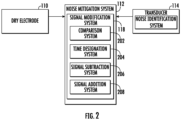
- FIG. 2 illustrates an example noise mitigation system 112 that includes a transducer 114 and a dry electrode 110 in accordance with example embodiments of the present disclosure.
- the noise mitigation system 112 can include a signal modification system 118.
- the system modification system 118 can include a comparison system 202, a time designation system 204, and a signal subtraction system 206, and signal addition system 208.
- the comparison system 202 can compare the first signal received from the dry electrode 110 to the noise signal received from the transducer 114. In some examples, the comparison between the two signals can determine how the signal is modified. For example, if the first signal is large relative to the noise signal, the noise signal may be ignored for the period of time in which the first signal is large. Conversely, if the noise signal is large relative to the first signal, the signal modification system can discard the first signal for that period of time. In some examples, the comparison system 202 can determine the type of modification that the signal modification system 118 will perform.
- the comparison system 202 can determine whether the noise signal needs to be subtracted from the first signal, whether the noise signal needs to be added to the first signal, or whether the signal modification system 118 should designate one or more time periods as discardable.
- the signal subtraction system 206 can modify the first signal by subtracting the noise signal from it.
- the signal addition system 208 can add the noise signal to the first symbol.
- the time designation system 204 can generate time series data associated with the level of noise in the noise signal.
- Each data point in the time series data can represent a discrete period of time relative to the noise signal and the first signal. For example, if each point represents 1/10th of a second, the time series data for the first 10 seconds will include 100 discrete data points.
- each data point can indicate whether or not the corresponding point in the first signal should be retained or discarded.
- each value can be a Boolean value (e.g., either true or false).
- the time designation system 204 can generate a marker when the noise signal exceeds a predetermined threshold (e.g., when the noise signal is sufficient to degrade the first signal to a predetermined degree) and another marker when the noise signal falls back below the predetermined threshold.
- a predetermined threshold e.g., when the noise signal is sufficient to degrade the first signal to a predetermined degree
- another marker when the noise signal falls back below the predetermined threshold.
- the noise mitigation system 112 can receive a first signal from the dry electrode 110.
- the dry electrode can gather data from the skin of a user by detecting bioelectrical or electrophysiological signals (e.g., generated by cells or tissues within the user).
- the first signal can represent the bioelectrical or electrophysiological signal transmitted by the dry electrode 110 to the noise mitigation system 112.
- the noise mitigation system 112 can receive a noise signal from the transducer 114.
- the noise signal can be analyzed by the noise of notification system 120 to determine whether the noise level exceeds a predetermined threshold. In some examples, if the noise signal does not exceed a predetermined threshold no signal modification is necessary.
- Figure 3 depicts the front view of an example wearable device 300 according to example embodiments of the present disclosure.
- the wearable device 300 may be a wristband, a bracelet, a wristwatch, an armband, a ring placed around a digit of the user, or other wearable products that may be equipped with sensors as described in the present disclosure.
- the wearable device 300 is configured with a display 302, a device housing 304, a band 306, and one or more additional sensors 308.
- the display 302 can be configured to present to a user data relating to the user's skin temperature, heart rate, electroencephalograms, electrocardiograms, electromyography, electrooculograms, and other physiological data of the user (e.g., blood oxygen level).
- the display 302 can also be configured to convey data from additional ambient sensors contained within the wearable device 300.
- Example information conveyed on the display 302 from these additional ambient sensors can include a positioning, altitude, and weather of a location associated with the user.
- the display 302 can also convey data regarding motion of the user (e.g., whether the user is stationary, walking, and/or running).
- the display 302 can be configured to receive data input by the user.
- a user can, by input on the display, request that the user computing device 300 generate additional data for display to the user (e.g., electrocardiograph data).
- the display can present instructions to the user (e.g., instructions to place one or more fingers on sensor 310) to obtain the data requested.
- the display 302 can display instructions to the user (e.g., please continue to hold your finger against the sensor for 10 seconds).
- the device housing 304 can be configured to contain one or more sensors described in the present disclosure.
- Example sensors contained by the device housing 304 can include skin temperature sensors, internal device temperature sensors, location sensors (e.g., GPS), motions sensors, altitude sensors, heart rate sensors, audio sensors, pressure sensors, and other physiological sensors (e.g., blood oxygen level sensors).
- the device housing 304 can also be configured to include one or more processors.
- the band 306 can be configured to secure the wearable device 100 around an arm the user by, for example, connecting ends of the band 306 with a buckle, clasp, or other similar securing device, thereby allowing the wearable device 100 to be worn by the user.
- the one or more additional sensors 308 can include a dry electrode.
- a dry electrode can allow data to be gathered from the skin of a user without the need to apply any electrolyte gel to the skin of the user.
- a user can generate bioelectrical or electrophysiological signals (e.g., generated by cells or tissues within the user) that can be detected by the dry electrode 110.
- the signal measured by the dry electrode 110 can be referred to as the first signal.
- the first signal can be measured and recorded in the form of electroencephalograms, electrocardiograms, electromyography, electrooculograms, etc.
- the dry electrode can be an active electrode or a passive electrode.
- FIG. 4 illustrates an example noise mitigation system (e.g., noise mitigation system 112 in FIG. 1 ) in accordance with example embodiments of the present disclosure.
- a dry electrode 110 can capture and/or detect an electrophysiological signal and transmit it along the first signal path 402.
- the first signal path can include signal amplification and/or amplification to clean or improve the first signal.
- the transducer 114 can detect a noise signal based on one or more sources of noise (e.g., changes in pressure, changes in capacitance, movement of the sensor, and so on).
- the noise signal can be amplified and filtered 404.
- Both the first signal and the noise signal can be transmitted to a signal modifier 406.
- the signal modifier 406 can modify the signal as discussed above (e.g., subtracted, added, compared, and so on).
- the signal can be used for one or more measurements 408, including, but not limited to electroencephalograms, electrocardiograms, electromyography, electrooculograms.
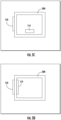
- FIGS. 5A-5F illustrates a variety of example configurations of a noise mitigation system in accordance with example embodiments of the present disclosure.
- FIG. 5A illustrates an example configuration including the housing 304 of the user computing device (e.g., user computing device 100 in FIG. 1 ), a dry electrode 110, a port 502 from the inside of the housing to the outside, and a transducer 114.
- the transducer 114 is a microphone (or other audio sensor) that can measure audio signals outside the user computing device 100 through the port 502.
- the audio signals are associated with noise in the first signal due to translational movement of the dry electrode 110.
- the transducer 114 may also detect a significant amount of audio noise that is not related to noise in the first signal.
- FIG. 5B illustrates an example configuration including the housing 304 of the user computing device (e.g., user computing device 100 in FIG. 1 ), a port integrated into the dry electrode itself 504, and a transducer 114.
- the port is integrated into the dry electrode itself creating an integrated port electrode 504.
- the port is made using micro-perforations through the electrode into the outside environment.
- the transducer 114 is a microphone (or other audio sensor) that can measure audio signals outside the user computing device 100 through the integrated port electrode 504.
- the audio signals are associated with noise in the first signal due to translational movement of the dry electrode 110.
- the transducer 114 may also detect a significant amount of audio noise that is not related to noise in the first signal.
- FIG. 5C illustrates an example configuration including the housing 304 of the user computing device (e.g., user computing device 100 in FIG. 1 ), an electrode 110, and a transducer 114.
- the dry electrode 110 can measure a signal from outside the housing 304 while the transducer 114 (a microphone or other audio sensor) can measure audio signals inside the housing 304 of the user computing device 100.
- the transducer 114 a microphone or other audio sensor
- FIG. 5D illustrates an example configuration including the housing 304 of the user computing device (e.g., user computing device 100 in FIG. 1 ), a dry electrode 110, and a pressure sensor transducer 114.
- the transducer 114 is a pressure sensor that can measure differences in pressure applied to the dry electrode 110. The differences in pressure can be associated with noise in the first signal.
- FIG. 5E illustrates an example configuration including the housing 304 of the user computing device (e.g., user computing device 100 in FIG. 1 ), two electrodes separated by a dielectric, a transducer 114, a signal processing system 512, and a signal modifier 514.
- the transducer 114 is a mutual capacitance sensor.
- the two electrodes can generate a first signal based on a determination of a difference of the mutual coupling between the two electrodes caused by an object (e.g., a finger).
- the transducer 114 can detect changes in the measured capacitance.
- the system also includes a signal processing system 512 for filtering and amplifying the first signal.
- FIG. 5F illustrates an example configuration including the housing 304 of the user computing device (e.g., user computing device 100 in FIG. 1 ), an electrode 110, a transducer 114, a signal processing system 512, and a signal modifier 514.
- the transducer 114 is a self-capacitance sensor. Similar to FIG. 5E , the dry electrode measures the capacitance as the first signal and the transducer 114 measures changes in capacitance.
- FIG. 6 illustrates an example user interface for a smartwatch 600 in accordance with example embodiments of the present disclosure.
- a smartwatch 600 includes a display 602.
- the smartwatch includes one pressure sensor 606.
- the user can press on the pressure sensor 606.
- the smartwatch 600 can determine that the user should apply additional pressure.
- the smartwatch can display a prompt 604 in the display 602 directing the user to increase the amount of pressure applied.
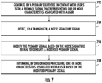
- FIG. 7 is a flowchart depicting an example process of mitigating noise in a user computing device in accordance with example embodiments of the present disclosure.
- One or more portion(s) of the method can be implemented by one or more computing devices such as, for example, the computing devices described herein.
- one or more portion(s) of the method can be implemented as an algorithm on the hardware components of the device(s) described herein.
- FIG. 7 depicts elements performed in a particular order for purposes of illustration and discussion.
- the method can be implemented by one or more computing devices, such as one or more of the computing devices depicted in FIGS. 1-3 .
- a user computing device (e.g., user computing device 100 in FIG. 1 ) includes a first electrode and a transducer.
- the user computing device 100 at 702, generates, by a first electrode in contact with a user's skin, a first signal that represents one or more characteristics associated with a user.
- the physiological signal sensor is a dry electrode in contact with a user's skin.
- the dry electrode can be a single metal contact that, when placed in contact with the user's skin, can generate a first signal in response to one or more characteristics of the user's skin or body.
- the user computing device 100 can, at 704, generate a noise signature signal via a transducer.
- the transducer includes an audio sensor situated to detect audio signals internal to the user computing device generated by lateral movement of the user computing device along the skin of the user.
- the transducer is a pressure sensor configured to determine variations in the pressure applied by a user.
- the transducer can be a capacitance sensor and the noise signature signal can represent changes in the area in which changes in differences in effective capacitance are detected.
- the transducer is an accelerometer and the noise signature signal represents a movement of the user computing device.
- the user computing device 100 can, at 706, modify the first signal based on the noise signature signal to generate a modified first signal.
- the first signal and the noise signature signal can be represented in one of the time domain or the frequency domain.
- modifying the first signal comprises subtracting the noise signature signal from the first signal to generate the modified first signal.
- modifying the first signal can comprise determining, at a particular time, whether the noise signature signal exceeds a predetermined threshold value. In accordance with a determination that the noise signature exceeds the predetermined threshold value, the user computing device 100 can store a timestamp of the particular time. The user computing device 100 can exclude the first signal associated with the timestamp from consideration when determining one or more characteristics associated with a user based on the modified first signal.
- the user computing device 100 can utilize a predetermined amount of time associated with gathering sufficient data to determine one or more characteristics associated with the user. In some examples, before the predetermined amount of time has elapsed, the user computing device can determine that the modified first signal includes data sufficient to determine one or more characteristics associated with the user. For example, if the user computing device 100 is estimating the heart rate of a user, the user computing device 100 can determine that it has enough data to estimate the heart rate of a user before the predetermined amount of time has already elapsed.
- the user computing device 100 can present, on a display associated with the user computing device 100, a notification that the user can disengage from contact with the dry electrode.
- the user computing device 100 can utilize a predetermined amount of time associated with gathering sufficient data to determine one or more characteristics associated with the user. When the predetermined amount of time has elapsed, the user computing device 100 can determine that the modified first signal does not include data sufficient to determine one or more characteristics associated with the user. The user computing device 100 can present, on a display associated with the user computing device 100, a request that the user continues to remain in contact with the dry electrode.
- the transducer can be a pressure sensor.
- the user computing device 100 can detect, using the transducer based on the noise signature signal, a change in pressure applied by the user.
- the user computing device 100 can determine that the change in pressure applied by the user exceeds a predetermined threshold. In accordance with a determination that the change in pressure applied by the user exceeds the predetermined threshold, the user computing device 100 can display a message to the user requesting the user to alter the pressure applied.
- the user computing device 100 can, at 708, determine one or more characteristics associated with a user based on the modified first signal.
- the one or more characteristics associated with the user include the presence of sweat on a surface of the user's skin.
- the presence of sweat on the surface of the user's skin is used to estimate a stress level associated with the user.
- the one or more characteristics associated with the user can include an impedance value as measured between two points on the user's skin.
- the impedance value as measured between two points on the user's skin can be used to estimate a stress level associated with the user.
- server processes discussed herein may be implemented using a single server or multiple servers working in combination.
- Databases and applications may be implemented on a single system or distributed across multiple systems. Distributed components may operate sequentially or in parallel.
Landscapes
- Health & Medical Sciences (AREA)
- Life Sciences & Earth Sciences (AREA)
- Engineering & Computer Science (AREA)
- Molecular Biology (AREA)
- Animal Behavior & Ethology (AREA)
- Veterinary Medicine (AREA)
- Public Health (AREA)
- Physics & Mathematics (AREA)
- General Health & Medical Sciences (AREA)
- Biophysics (AREA)
- Pathology (AREA)
- Biomedical Technology (AREA)
- Heart & Thoracic Surgery (AREA)
- Medical Informatics (AREA)
- Surgery (AREA)
- Signal Processing (AREA)
- Physiology (AREA)
- Computer Vision & Pattern Recognition (AREA)
- Artificial Intelligence (AREA)
- Psychiatry (AREA)
- Cardiology (AREA)
- Radiology & Medical Imaging (AREA)
- Dermatology (AREA)
- Nuclear Medicine, Radiotherapy & Molecular Imaging (AREA)
- Dentistry (AREA)
- Oral & Maxillofacial Surgery (AREA)
- Pulmonology (AREA)
- Measurement And Recording Of Electrical Phenomena And Electrical Characteristics Of The Living Body (AREA)
Claims (14)
- Dispositif informatique utilisateur (100), le dispositif informatique utilisateur (100) comprenant :un boîtier (304) ;un capteur de signal physiologique configuré pour générer un premier signal relatif à une ou plusieurs caractéristiques associées à un utilisateur et agencé pour mesurer un signal provenant de l'extérieur du boîtier (304) ;un transducteur (114) configuré pour générer un signal de signature de bruit sur la base de la détection d'une ou de plusieurs sources de bruit ; etun ou plusieurs circuits de commande configurés pour :modifier le premier signal sur la base du signal de signature de bruit pour générer un premier signal modifié ; etdéterminer une ou plusieurs caractéristiques associées à un utilisateur sur la base du premier signal modifié, dans lequel le transducteur (114) comporte un capteur audio agencé à l'intérieur du boîtier (304) et situé pour détecter une source de bruit sous la forme de signaux audio internes au dispositif informatique utilisateur (100) générés par un mouvement latéral du dispositif informatique utilisateur (100) le long de la peau de l'utilisateur, caractérisé en ce quele capteur de signal physiologique est une électrode sèche (110) capable d'entrer en contact avec la peau d'un utilisateur.
- Dispositif informatique utilisateur (100) selon la revendication 1, dans lequel le transducteur (114) comprend également un
capteur de pression capable de déterminer des variations d'une pression appliquée par un utilisateur. - Dispositif informatique utilisateur (100) selon une quelconque revendication précédente, dans lequel la modification du premier signal comprend :
la soustraction, du premier signal, d'une partie de signal correspondant au signal de signature de bruit pour générer le premier signal modifié. - Dispositif informatique utilisateur (100) selon une quelconque revendication précédente, dans lequel le premier signal et le signal de signature de bruit sont représentés dans l'un d'un domaine temporel ou d'un domaine fréquentiel.
- Dispositif informatique utilisateur (100) selon une quelconque revendication précédente, dans lequelle transducteur (114) comporte également un capteur de mouvement et le signal de signature de bruit représente également un mouvementdu dispositif informatique utilisateur (100).
- Dispositif informatique utilisateur (100) selon une quelconque revendication précédente, dans lequelle transducteur (114) comporte également un capteur de capacité et le signal de signature de bruit représente égalementdes changements dans une zone dans laquelle des changements dans des différences de capacité effective sont détectés.
- Dispositif informatique utilisateur (100) selon une quelconque revendication précédente, dans lequel les une ou plusieurs caractéristiques associées à l'utilisateur comportent une présence de sueur sur une surface de la peau de l'utilisateur.
- Dispositif informatique utilisateur (100) selon la revendication 7, dans lequel
la présence de sueur à la surface de la peau de l'utilisateur est utilisée pour estimer un niveau de stress associé à l'utilisateur. - Dispositif informatique utilisateur (100) selon une quelconque revendication précédente, dans lequel les une ou plusieurs caractéristiques associées à l'utilisateur comportent une valeur d'impédance telle que mesurée entre deux points sur la peau de l'utilisateur.
- Dispositif informatique utilisateur (100) selon la revendication 9, dans lequel le dispositif informatique utilisateur est configuré pour estimer un niveau de stress associé à l'utilisateur sur la base de la valeur d'impédance.
- Procédé mis en œuvre par ordinateur pour supprimer le bruit d'un signal généré par une électrode sèche, le procédé comprenant :la génération, par une électrode sèche (110) dans un dispositif informatique utilisateur (100), en contact avec la peau de l'utilisateur, d'un premier signal représentant une ou plusieurs caractéristiques associées à un utilisateur et agencé pour mesurer un signal provenant de l'extérieur d'un boîtier (304) du dispositif informatique utilisateur (100) ;la détection, par un transducteur (114), d'un signal de signature de bruit ;la modification, par un ou plusieurs processeurs (102), du premier signal sur la base du signal de signature de bruit pour générer un premier signal modifié ; etla détermination, par un ou plusieurs processeurs (102), d'une ou plusieurs caractéristiques associées à un utilisateur sur la base du premier signal modifié, dans lequelle transducteur (114) comporte un capteur audio agencé à l'intérieur du boîtier (304) et situé pour détecter une source de bruit sous la forme de signaux audio internes au dispositif informatique utilisateur (100) générés par un mouvement latéral du dispositif informatique utilisateur (100) le long de la peau de l'utilisateur.
- Procédé mis en œuvre par ordinateur selon la revendication 11, dans lequel la modification du premier signal comprend :le fait de déterminer, par les un ou plusieurs processeurs (102) à un moment particulier, si le signal de signature de bruit dépasse une valeur de seuil prédéterminée ;selon une détermination du fait que le signal de signature de bruit dépasse la valeur de seuil prédéterminée, le stockage, par les un ou plusieurs processeurs (102), d'un horodatage du moment particulier ; etl'exclusion, par les un ou plusieurs processeurs (102), du premier signal associé à l'horodatage de la prise en compte lors de la détermination d'une ou de plusieurs caractéristiques associées à un utilisateur sur la base du premier signal modifié.
- Procédé mis en œuvre par ordinateur selon la revendication 11 ou 12, dans lequel le dispositif informatique utilisateur (100) comporte une quantité de temps prédéterminée associée à la collecte de données suffisantes pour déterminer une ou plusieurs caractéristiques associées à l'utilisateur, le procédé comprenant également :
avant que la quantité de temps prédéterminée ne soit écoulée :la détermination, par les un ou plusieurs processeurs (102), du fait que le premier signal modifié comporte des données suffisantes pour déterminer une ou plusieurs caractéristiques associées à l'utilisateur ; etla présentation, par les un ou plusieurs processeurs (102) sur un écran (302) associé au dispositif informatique utilisateur (100), d'une notification indiquant que l'utilisateur peut se dégager du contact avec l'électrode sèche (110). - Procédé mis en œuvre par ordinateur selon l'une quelconque des revendications 11 à 13, dans lequel le dispositif informatique utilisateur (100) comporte une quantité de temps prédéterminée associée à la collecte de données suffisantes pour déterminer une ou plusieurs caractéristiques associées à l'utilisateur, le procédé comprenant également :
lorsque la quantité de temps prédéterminée s'est écoulée :la détermination, par les un ou plusieurs processeurs (102), du fait que le premier signal modifié ne comporte pas de données suffisantes pour déterminer une ou plusieurs caractéristiques associées à l'utilisateur ; etla présentation, par les un ou plusieurs processeurs (102) sur un écran (302) associé au dispositif informatique utilisateur (100), d'une demande pour que l'utilisateur continue à rester en contact avec l'électrode sèche (110).
Applications Claiming Priority (1)
| Application Number | Priority Date | Filing Date | Title |
|---|---|---|---|
| PCT/US2021/042183 WO2023003532A1 (fr) | 2021-07-19 | 2021-07-19 | Système et procédés de détection et d'élimination de bruit électrique dans des électrodes sèches |
Publications (2)
| Publication Number | Publication Date |
|---|---|
| EP4153041A1 EP4153041A1 (fr) | 2023-03-29 |
| EP4153041B1 true EP4153041B1 (fr) | 2024-11-13 |
Family
ID=77543584
Family Applications (1)
| Application Number | Title | Priority Date | Filing Date |
|---|---|---|---|
| EP21762831.2A Active EP4153041B1 (fr) | 2021-07-19 | 2021-07-19 | Système et procédés de détection et d'élimination de bruit électrique dans des électrodes sèches |
Country Status (4)
| Country | Link |
|---|---|
| US (1) | US20240090844A1 (fr) |
| EP (1) | EP4153041B1 (fr) |
| CN (1) | CN115867184A (fr) |
| WO (1) | WO2023003532A1 (fr) |
Citations (2)
| Publication number | Priority date | Publication date | Assignee | Title |
|---|---|---|---|---|
| WO2014163443A1 (fr) * | 2013-04-05 | 2014-10-09 | Samsung Electronics Co., Ltd. | Stéthoscope électronique, appareil diagnostique automatique et procédé |
| US20210106257A1 (en) * | 2019-03-20 | 2021-04-15 | Anhui Huami Information Technology Co., Ltd. | Wearable device, signal processing method and apparatus |
Family Cites Families (4)
| Publication number | Priority date | Publication date | Assignee | Title |
|---|---|---|---|---|
| US7733224B2 (en) * | 2006-06-30 | 2010-06-08 | Bao Tran | Mesh network personal emergency response appliance |
| EP3027007A2 (fr) * | 2013-05-20 | 2016-06-08 | AliphCom | Combinaison haut-parleur et source de lumière réagissant à un ou plusieurs états d'un organisme sur la base de données de capteur |
| US20150264459A1 (en) * | 2014-03-12 | 2015-09-17 | Aliphcom | Combination speaker and light source responsive to state(s) of an environment based on sensor data |
| EP4242614A3 (fr) * | 2014-07-01 | 2023-11-29 | Injectsense, Inc. | Capteurs d'implant fermés hermétiquement ayant une architecture d'empilement vertical |
-
2021
- 2021-07-19 WO PCT/US2021/042183 patent/WO2023003532A1/fr not_active Ceased
- 2021-07-19 US US18/013,813 patent/US20240090844A1/en active Pending
- 2021-07-19 EP EP21762831.2A patent/EP4153041B1/fr active Active
- 2021-07-19 CN CN202180046342.5A patent/CN115867184A/zh active Pending
Patent Citations (2)
| Publication number | Priority date | Publication date | Assignee | Title |
|---|---|---|---|---|
| WO2014163443A1 (fr) * | 2013-04-05 | 2014-10-09 | Samsung Electronics Co., Ltd. | Stéthoscope électronique, appareil diagnostique automatique et procédé |
| US20210106257A1 (en) * | 2019-03-20 | 2021-04-15 | Anhui Huami Information Technology Co., Ltd. | Wearable device, signal processing method and apparatus |
Also Published As
| Publication number | Publication date |
|---|---|
| US20240090844A1 (en) | 2024-03-21 |
| WO2023003532A1 (fr) | 2023-01-26 |
| EP4153041A1 (fr) | 2023-03-29 |
| CN115867184A (zh) | 2023-03-28 |
Similar Documents
| Publication | Publication Date | Title |
|---|---|---|
| CN111356401B (zh) | 使用可穿戴传感器和云驻留分析来连续检测和监测心律失常 | |
| US10045708B2 (en) | Method of detecting the wearing limb of a wearable electronic device | |
| US20140128753A1 (en) | Piezoelectric heart rate sensing for wearable devices or mobile devices | |
| CN112515629B (zh) | 用于估计生物信息的设备 | |
| CN103596493A (zh) | 压力测量设备和方法 | |
| US10265027B2 (en) | Biosignal processing method and biosignal processing apparatus | |
| EP3701859B1 (fr) | Appareil et procede d'estimation de bio-information | |
| US20230255503A1 (en) | Apparatus and method for estimating bio-information | |
| CN111000543B (zh) | 用于估计血压的设备 | |
| CN111012322B (zh) | 用于估计血压的设备 | |
| CN112107303A (zh) | 校准生物信息估计模型的设备和方法及生物信息估计设备 | |
| Goverdovsky et al. | Co-located multimodal sensing: A next generation solution for wearable health | |
| CN112957007B (zh) | 用于估计生物信息的设备 | |
| US11969234B2 (en) | Apparatus and method for estimating bio-information | |
| US11540728B2 (en) | Heart sound measurement using mobile devices | |
| CN113197544B (zh) | 信号处理设备以及用于估计生物信息的设备 | |
| US10448896B2 (en) | Method and apparatus for processing bio-signals using recursive estimation | |
| EP4153041B1 (fr) | Système et procédés de détection et d'élimination de bruit électrique dans des électrodes sèches | |
| TWI708162B (zh) | 用於可穿戴式感測器之設備及方法、及相關電腦程式 | |
| US20200281498A1 (en) | Bio-signal detection | |
| US11844588B2 (en) | Apparatus and method for detecting characteristic point of oscillometric envelope and apparatus for estimating bio-information | |
| JP7180259B2 (ja) | 生体情報解析装置、生体情報解析方法、および生体情報解析システム | |
| JP7206663B2 (ja) | 検出装置、ウェアラブルセンシングデバイス、検出方法、およびプログラム | |
| KR102690209B1 (ko) | 휴대용 심전도 측정장치 | |
| US20170055915A1 (en) | Method and system for detecting pain of users |
Legal Events
| Date | Code | Title | Description |
|---|---|---|---|
| STAA | Information on the status of an ep patent application or granted ep patent |
Free format text: STATUS: UNKNOWN |
|
| STAA | Information on the status of an ep patent application or granted ep patent |
Free format text: STATUS: THE INTERNATIONAL PUBLICATION HAS BEEN MADE |
|
| PUAI | Public reference made under article 153(3) epc to a published international application that has entered the european phase |
Free format text: ORIGINAL CODE: 0009012 |
|
| STAA | Information on the status of an ep patent application or granted ep patent |
Free format text: STATUS: REQUEST FOR EXAMINATION WAS MADE |
|
| 17P | Request for examination filed |
Effective date: 20221220 |
|
| AK | Designated contracting states |
Kind code of ref document: A1 Designated state(s): AL AT BE BG CH CY CZ DE DK EE ES FI FR GB GR HR HU IE IS IT LI LT LU LV MC MK MT NL NO PL PT RO RS SE SI SK SM TR |
|
| STAA | Information on the status of an ep patent application or granted ep patent |
Free format text: STATUS: EXAMINATION IS IN PROGRESS |
|
| 17Q | First examination report despatched |
Effective date: 20230921 |
|
| RIC1 | Information provided on ipc code assigned before grant |
Ipc: A61B 5/0531 20210101ALN20240426BHEP Ipc: A61B 5/00 20060101ALI20240426BHEP Ipc: A61B 5/0205 20060101AFI20240426BHEP |
|
| GRAP | Despatch of communication of intention to grant a patent |
Free format text: ORIGINAL CODE: EPIDOSNIGR1 |
|
| STAA | Information on the status of an ep patent application or granted ep patent |
Free format text: STATUS: GRANT OF PATENT IS INTENDED |
|
| RIC1 | Information provided on ipc code assigned before grant |
Ipc: A61B 5/0531 20210101ALN20240513BHEP Ipc: A61B 5/00 20060101ALI20240513BHEP Ipc: A61B 5/0205 20060101AFI20240513BHEP |
|
| DAV | Request for validation of the european patent (deleted) | ||
| DAX | Request for extension of the european patent (deleted) | ||
| INTG | Intention to grant announced |
Effective date: 20240604 |
|
| RAP3 | Party data changed (applicant data changed or rights of an application transferred) |
Owner name: FITBIT LLC |
|
| GRAS | Grant fee paid |
Free format text: ORIGINAL CODE: EPIDOSNIGR3 |
|
| GRAA | (expected) grant |
Free format text: ORIGINAL CODE: 0009210 |
|
| STAA | Information on the status of an ep patent application or granted ep patent |
Free format text: STATUS: THE PATENT HAS BEEN GRANTED |
|
| AK | Designated contracting states |
Kind code of ref document: B1 Designated state(s): AL AT BE BG CH CY CZ DE DK EE ES FI FR GB GR HR HU IE IS IT LI LT LU LV MC MK MT NL NO PL PT RO RS SE SI SK SM TR |
|
| P01 | Opt-out of the competence of the unified patent court (upc) registered |
Free format text: CASE NUMBER: APP_54737/2024 Effective date: 20241004 |
|
| REG | Reference to a national code |
Ref country code: GB Ref legal event code: FG4D |
|
| REG | Reference to a national code |
Ref country code: CH Ref legal event code: EP |
|
| REG | Reference to a national code |
Ref country code: IE Ref legal event code: FG4D |
|
| REG | Reference to a national code |
Ref country code: DE Ref legal event code: R096 Ref document number: 602021021836 Country of ref document: DE |
|
| REG | Reference to a national code |
Ref country code: LT Ref legal event code: MG9D |
|
| REG | Reference to a national code |
Ref country code: NL Ref legal event code: MP Effective date: 20241113 |
|
| PG25 | Lapsed in a contracting state [announced via postgrant information from national office to epo] |
Ref country code: IS Free format text: LAPSE BECAUSE OF FAILURE TO SUBMIT A TRANSLATION OF THE DESCRIPTION OR TO PAY THE FEE WITHIN THE PRESCRIBED TIME-LIMIT Effective date: 20250313 Ref country code: PT Free format text: LAPSE BECAUSE OF FAILURE TO SUBMIT A TRANSLATION OF THE DESCRIPTION OR TO PAY THE FEE WITHIN THE PRESCRIBED TIME-LIMIT Effective date: 20250313 Ref country code: HR Free format text: LAPSE BECAUSE OF FAILURE TO SUBMIT A TRANSLATION OF THE DESCRIPTION OR TO PAY THE FEE WITHIN THE PRESCRIBED TIME-LIMIT Effective date: 20241113 |
|
| PG25 | Lapsed in a contracting state [announced via postgrant information from national office to epo] |
Ref country code: NL Free format text: LAPSE BECAUSE OF FAILURE TO SUBMIT A TRANSLATION OF THE DESCRIPTION OR TO PAY THE FEE WITHIN THE PRESCRIBED TIME-LIMIT Effective date: 20241113 Ref country code: FI Free format text: LAPSE BECAUSE OF FAILURE TO SUBMIT A TRANSLATION OF THE DESCRIPTION OR TO PAY THE FEE WITHIN THE PRESCRIBED TIME-LIMIT Effective date: 20241113 |
|
| REG | Reference to a national code |
Ref country code: AT Ref legal event code: MK05 Ref document number: 1740992 Country of ref document: AT Kind code of ref document: T Effective date: 20241113 |
|
| PG25 | Lapsed in a contracting state [announced via postgrant information from national office to epo] |
Ref country code: BG Free format text: LAPSE BECAUSE OF FAILURE TO SUBMIT A TRANSLATION OF THE DESCRIPTION OR TO PAY THE FEE WITHIN THE PRESCRIBED TIME-LIMIT Effective date: 20241113 |
|
| PG25 | Lapsed in a contracting state [announced via postgrant information from national office to epo] |
Ref country code: ES Free format text: LAPSE BECAUSE OF FAILURE TO SUBMIT A TRANSLATION OF THE DESCRIPTION OR TO PAY THE FEE WITHIN THE PRESCRIBED TIME-LIMIT Effective date: 20241113 |
|
| PG25 | Lapsed in a contracting state [announced via postgrant information from national office to epo] |
Ref country code: NO Free format text: LAPSE BECAUSE OF FAILURE TO SUBMIT A TRANSLATION OF THE DESCRIPTION OR TO PAY THE FEE WITHIN THE PRESCRIBED TIME-LIMIT Effective date: 20250213 |
|
| PG25 | Lapsed in a contracting state [announced via postgrant information from national office to epo] |
Ref country code: AT Free format text: LAPSE BECAUSE OF FAILURE TO SUBMIT A TRANSLATION OF THE DESCRIPTION OR TO PAY THE FEE WITHIN THE PRESCRIBED TIME-LIMIT Effective date: 20241113 Ref country code: GR Free format text: LAPSE BECAUSE OF FAILURE TO SUBMIT A TRANSLATION OF THE DESCRIPTION OR TO PAY THE FEE WITHIN THE PRESCRIBED TIME-LIMIT Effective date: 20250214 Ref country code: LV Free format text: LAPSE BECAUSE OF FAILURE TO SUBMIT A TRANSLATION OF THE DESCRIPTION OR TO PAY THE FEE WITHIN THE PRESCRIBED TIME-LIMIT Effective date: 20241113 |
|
| PG25 | Lapsed in a contracting state [announced via postgrant information from national office to epo] |
Ref country code: PL Free format text: LAPSE BECAUSE OF FAILURE TO SUBMIT A TRANSLATION OF THE DESCRIPTION OR TO PAY THE FEE WITHIN THE PRESCRIBED TIME-LIMIT Effective date: 20241113 |
|
| PG25 | Lapsed in a contracting state [announced via postgrant information from national office to epo] |
Ref country code: RS Free format text: LAPSE BECAUSE OF FAILURE TO SUBMIT A TRANSLATION OF THE DESCRIPTION OR TO PAY THE FEE WITHIN THE PRESCRIBED TIME-LIMIT Effective date: 20250213 |
|
| PG25 | Lapsed in a contracting state [announced via postgrant information from national office to epo] |
Ref country code: SM Free format text: LAPSE BECAUSE OF FAILURE TO SUBMIT A TRANSLATION OF THE DESCRIPTION OR TO PAY THE FEE WITHIN THE PRESCRIBED TIME-LIMIT Effective date: 20241113 |
|
| PG25 | Lapsed in a contracting state [announced via postgrant information from national office to epo] |
Ref country code: DK Free format text: LAPSE BECAUSE OF FAILURE TO SUBMIT A TRANSLATION OF THE DESCRIPTION OR TO PAY THE FEE WITHIN THE PRESCRIBED TIME-LIMIT Effective date: 20241113 |
|
| PG25 | Lapsed in a contracting state [announced via postgrant information from national office to epo] |
Ref country code: EE Free format text: LAPSE BECAUSE OF FAILURE TO SUBMIT A TRANSLATION OF THE DESCRIPTION OR TO PAY THE FEE WITHIN THE PRESCRIBED TIME-LIMIT Effective date: 20241113 |
|
| PG25 | Lapsed in a contracting state [announced via postgrant information from national office to epo] |
Ref country code: RO Free format text: LAPSE BECAUSE OF FAILURE TO SUBMIT A TRANSLATION OF THE DESCRIPTION OR TO PAY THE FEE WITHIN THE PRESCRIBED TIME-LIMIT Effective date: 20241113 |
|
| PG25 | Lapsed in a contracting state [announced via postgrant information from national office to epo] |
Ref country code: SK Free format text: LAPSE BECAUSE OF FAILURE TO SUBMIT A TRANSLATION OF THE DESCRIPTION OR TO PAY THE FEE WITHIN THE PRESCRIBED TIME-LIMIT Effective date: 20241113 |
|
| PG25 | Lapsed in a contracting state [announced via postgrant information from national office to epo] |
Ref country code: CZ Free format text: LAPSE BECAUSE OF FAILURE TO SUBMIT A TRANSLATION OF THE DESCRIPTION OR TO PAY THE FEE WITHIN THE PRESCRIBED TIME-LIMIT Effective date: 20241113 |
|
| PG25 | Lapsed in a contracting state [announced via postgrant information from national office to epo] |
Ref country code: IT Free format text: LAPSE BECAUSE OF FAILURE TO SUBMIT A TRANSLATION OF THE DESCRIPTION OR TO PAY THE FEE WITHIN THE PRESCRIBED TIME-LIMIT Effective date: 20241113 |
|
| REG | Reference to a national code |
Ref country code: DE Ref legal event code: R097 Ref document number: 602021021836 Country of ref document: DE |
|
| PG25 | Lapsed in a contracting state [announced via postgrant information from national office to epo] |
Ref country code: SE Free format text: LAPSE BECAUSE OF FAILURE TO SUBMIT A TRANSLATION OF THE DESCRIPTION OR TO PAY THE FEE WITHIN THE PRESCRIBED TIME-LIMIT Effective date: 20241113 |
|
| PLBE | No opposition filed within time limit |
Free format text: ORIGINAL CODE: 0009261 |
|
| STAA | Information on the status of an ep patent application or granted ep patent |
Free format text: STATUS: NO OPPOSITION FILED WITHIN TIME LIMIT |
|
| PGFP | Annual fee paid to national office [announced via postgrant information from national office to epo] |
Ref country code: DE Payment date: 20250729 Year of fee payment: 5 |
|
| PGFP | Annual fee paid to national office [announced via postgrant information from national office to epo] |
Ref country code: GB Payment date: 20250728 Year of fee payment: 5 |
|
| PGFP | Annual fee paid to national office [announced via postgrant information from national office to epo] |
Ref country code: FR Payment date: 20250725 Year of fee payment: 5 |
|
| 26N | No opposition filed |
Effective date: 20250814 |
|
| REG | Reference to a national code |
Ref country code: CH Ref legal event code: H13 Free format text: ST27 STATUS EVENT CODE: U-0-0-H10-H13 (AS PROVIDED BY THE NATIONAL OFFICE) Effective date: 20260224 |
|
| PG25 | Lapsed in a contracting state [announced via postgrant information from national office to epo] |
Ref country code: LU Free format text: LAPSE BECAUSE OF NON-PAYMENT OF DUE FEES Effective date: 20250719 |
|
| REG | Reference to a national code |
Ref country code: BE Ref legal event code: MM Effective date: 20250731 |
|
| PG25 | Lapsed in a contracting state [announced via postgrant information from national office to epo] |
Ref country code: BE Free format text: LAPSE BECAUSE OF NON-PAYMENT OF DUE FEES Effective date: 20250731 |
|
| PG25 | Lapsed in a contracting state [announced via postgrant information from national office to epo] |
Ref country code: CH Free format text: LAPSE BECAUSE OF NON-PAYMENT OF DUE FEES Effective date: 20250731 |