EP4153439B1 - Verfahren zur steuerung einer antriebsstrangeinheit für ein kraftfahrzeug mit hybridem elektrischen getriebe - Google Patents
Verfahren zur steuerung einer antriebsstrangeinheit für ein kraftfahrzeug mit hybridem elektrischen getriebe Download PDFInfo
- Publication number
- EP4153439B1 EP4153439B1 EP21725465.5A EP21725465A EP4153439B1 EP 4153439 B1 EP4153439 B1 EP 4153439B1 EP 21725465 A EP21725465 A EP 21725465A EP 4153439 B1 EP4153439 B1 EP 4153439B1
- Authority
- EP
- European Patent Office
- Prior art keywords
- torque
- electric machine
- internal combustion
- combustion engine
- auxiliary electric
- Prior art date
- Legal status (The legal status is an assumption and is not a legal conclusion. Google has not performed a legal analysis and makes no representation as to the accuracy of the status listed.)
- Active
Links
Images
Classifications
-
- B—PERFORMING OPERATIONS; TRANSPORTING
- B60—VEHICLES IN GENERAL
- B60K—ARRANGEMENT OR MOUNTING OF PROPULSION UNITS OR OF TRANSMISSIONS IN VEHICLES; ARRANGEMENT OR MOUNTING OF PLURAL DIVERSE PRIME-MOVERS IN VEHICLES; AUXILIARY DRIVES FOR VEHICLES; INSTRUMENTATION OR DASHBOARDS FOR VEHICLES; ARRANGEMENTS IN CONNECTION WITH COOLING, AIR INTAKE, GAS EXHAUST OR FUEL SUPPLY OF PROPULSION UNITS IN VEHICLES
- B60K6/00—Arrangement or mounting of plural diverse prime-movers for mutual or common propulsion, e.g. hybrid propulsion systems comprising electric motors and internal combustion engines
- B60K6/20—Arrangement or mounting of plural diverse prime-movers for mutual or common propulsion, e.g. hybrid propulsion systems comprising electric motors and internal combustion engines the prime-movers consisting of electric motors and internal combustion engines, e.g. HEVs
- B60K6/22—Arrangement or mounting of plural diverse prime-movers for mutual or common propulsion, e.g. hybrid propulsion systems comprising electric motors and internal combustion engines the prime-movers consisting of electric motors and internal combustion engines, e.g. HEVs characterised by apparatus, components or means specially adapted for HEVs
- B60K6/36—Arrangement or mounting of plural diverse prime-movers for mutual or common propulsion, e.g. hybrid propulsion systems comprising electric motors and internal combustion engines the prime-movers consisting of electric motors and internal combustion engines, e.g. HEVs characterised by apparatus, components or means specially adapted for HEVs characterised by the transmission gearings
-
- B—PERFORMING OPERATIONS; TRANSPORTING
- B60—VEHICLES IN GENERAL
- B60K—ARRANGEMENT OR MOUNTING OF PROPULSION UNITS OR OF TRANSMISSIONS IN VEHICLES; ARRANGEMENT OR MOUNTING OF PLURAL DIVERSE PRIME-MOVERS IN VEHICLES; AUXILIARY DRIVES FOR VEHICLES; INSTRUMENTATION OR DASHBOARDS FOR VEHICLES; ARRANGEMENTS IN CONNECTION WITH COOLING, AIR INTAKE, GAS EXHAUST OR FUEL SUPPLY OF PROPULSION UNITS IN VEHICLES
- B60K6/00—Arrangement or mounting of plural diverse prime-movers for mutual or common propulsion, e.g. hybrid propulsion systems comprising electric motors and internal combustion engines
- B60K6/20—Arrangement or mounting of plural diverse prime-movers for mutual or common propulsion, e.g. hybrid propulsion systems comprising electric motors and internal combustion engines the prime-movers consisting of electric motors and internal combustion engines, e.g. HEVs
- B60K6/22—Arrangement or mounting of plural diverse prime-movers for mutual or common propulsion, e.g. hybrid propulsion systems comprising electric motors and internal combustion engines the prime-movers consisting of electric motors and internal combustion engines, e.g. HEVs characterised by apparatus, components or means specially adapted for HEVs
- B60K6/38—Arrangement or mounting of plural diverse prime-movers for mutual or common propulsion, e.g. hybrid propulsion systems comprising electric motors and internal combustion engines the prime-movers consisting of electric motors and internal combustion engines, e.g. HEVs characterised by apparatus, components or means specially adapted for HEVs characterised by the driveline clutches
- B60K6/387—Actuated clutches, i.e. clutches engaged or disengaged by electric, hydraulic or mechanical actuating means
-
- B—PERFORMING OPERATIONS; TRANSPORTING
- B60—VEHICLES IN GENERAL
- B60K—ARRANGEMENT OR MOUNTING OF PROPULSION UNITS OR OF TRANSMISSIONS IN VEHICLES; ARRANGEMENT OR MOUNTING OF PLURAL DIVERSE PRIME-MOVERS IN VEHICLES; AUXILIARY DRIVES FOR VEHICLES; INSTRUMENTATION OR DASHBOARDS FOR VEHICLES; ARRANGEMENTS IN CONNECTION WITH COOLING, AIR INTAKE, GAS EXHAUST OR FUEL SUPPLY OF PROPULSION UNITS IN VEHICLES
- B60K6/00—Arrangement or mounting of plural diverse prime-movers for mutual or common propulsion, e.g. hybrid propulsion systems comprising electric motors and internal combustion engines
- B60K6/20—Arrangement or mounting of plural diverse prime-movers for mutual or common propulsion, e.g. hybrid propulsion systems comprising electric motors and internal combustion engines the prime-movers consisting of electric motors and internal combustion engines, e.g. HEVs
- B60K6/42—Arrangement or mounting of plural diverse prime-movers for mutual or common propulsion, e.g. hybrid propulsion systems comprising electric motors and internal combustion engines the prime-movers consisting of electric motors and internal combustion engines, e.g. HEVs characterised by the architecture of the hybrid electric vehicle
- B60K6/44—Series-parallel type
- B60K6/442—Series-parallel switching type
-
- B—PERFORMING OPERATIONS; TRANSPORTING
- B60—VEHICLES IN GENERAL
- B60K—ARRANGEMENT OR MOUNTING OF PROPULSION UNITS OR OF TRANSMISSIONS IN VEHICLES; ARRANGEMENT OR MOUNTING OF PLURAL DIVERSE PRIME-MOVERS IN VEHICLES; AUXILIARY DRIVES FOR VEHICLES; INSTRUMENTATION OR DASHBOARDS FOR VEHICLES; ARRANGEMENTS IN CONNECTION WITH COOLING, AIR INTAKE, GAS EXHAUST OR FUEL SUPPLY OF PROPULSION UNITS IN VEHICLES
- B60K6/00—Arrangement or mounting of plural diverse prime-movers for mutual or common propulsion, e.g. hybrid propulsion systems comprising electric motors and internal combustion engines
- B60K6/20—Arrangement or mounting of plural diverse prime-movers for mutual or common propulsion, e.g. hybrid propulsion systems comprising electric motors and internal combustion engines the prime-movers consisting of electric motors and internal combustion engines, e.g. HEVs
- B60K6/50—Architecture of the driveline characterised by arrangement or kind of transmission units
- B60K6/54—Transmission for changing ratio
- B60K6/547—Transmission for changing ratio the transmission being a stepped gearing
-
- B—PERFORMING OPERATIONS; TRANSPORTING
- B60—VEHICLES IN GENERAL
- B60L—PROPULSION OF ELECTRICALLY-PROPELLED VEHICLES; SUPPLYING ELECTRIC POWER FOR AUXILIARY EQUIPMENT OF ELECTRICALLY-PROPELLED VEHICLES; ELECTRODYNAMIC BRAKE SYSTEMS FOR VEHICLES IN GENERAL; MAGNETIC SUSPENSION OR LEVITATION FOR VEHICLES; MONITORING OPERATING VARIABLES OF ELECTRICALLY-PROPELLED VEHICLES; ELECTRIC SAFETY DEVICES FOR ELECTRICALLY-PROPELLED VEHICLES
- B60L15/00—Methods, circuits, or devices for controlling the traction-motor speed of electrically-propelled vehicles
- B60L15/20—Methods, circuits, or devices for controlling the traction-motor speed of electrically-propelled vehicles for control of the vehicle or its driving motor to achieve a desired performance, e.g. speed, torque, programmed variation of speed
- B60L15/2045—Methods, circuits, or devices for controlling the traction-motor speed of electrically-propelled vehicles for control of the vehicle or its driving motor to achieve a desired performance, e.g. speed, torque, programmed variation of speed for optimising the use of energy
-
- B—PERFORMING OPERATIONS; TRANSPORTING
- B60—VEHICLES IN GENERAL
- B60L—PROPULSION OF ELECTRICALLY-PROPELLED VEHICLES; SUPPLYING ELECTRIC POWER FOR AUXILIARY EQUIPMENT OF ELECTRICALLY-PROPELLED VEHICLES; ELECTRODYNAMIC BRAKE SYSTEMS FOR VEHICLES IN GENERAL; MAGNETIC SUSPENSION OR LEVITATION FOR VEHICLES; MONITORING OPERATING VARIABLES OF ELECTRICALLY-PROPELLED VEHICLES; ELECTRIC SAFETY DEVICES FOR ELECTRICALLY-PROPELLED VEHICLES
- B60L15/00—Methods, circuits, or devices for controlling the traction-motor speed of electrically-propelled vehicles
- B60L15/20—Methods, circuits, or devices for controlling the traction-motor speed of electrically-propelled vehicles for control of the vehicle or its driving motor to achieve a desired performance, e.g. speed, torque, programmed variation of speed
- B60L15/2054—Methods, circuits, or devices for controlling the traction-motor speed of electrically-propelled vehicles for control of the vehicle or its driving motor to achieve a desired performance, e.g. speed, torque, programmed variation of speed by controlling transmissions or clutches
-
- B—PERFORMING OPERATIONS; TRANSPORTING
- B60—VEHICLES IN GENERAL
- B60L—PROPULSION OF ELECTRICALLY-PROPELLED VEHICLES; SUPPLYING ELECTRIC POWER FOR AUXILIARY EQUIPMENT OF ELECTRICALLY-PROPELLED VEHICLES; ELECTRODYNAMIC BRAKE SYSTEMS FOR VEHICLES IN GENERAL; MAGNETIC SUSPENSION OR LEVITATION FOR VEHICLES; MONITORING OPERATING VARIABLES OF ELECTRICALLY-PROPELLED VEHICLES; ELECTRIC SAFETY DEVICES FOR ELECTRICALLY-PROPELLED VEHICLES
- B60L50/00—Electric propulsion with power supplied within the vehicle
- B60L50/50—Electric propulsion with power supplied within the vehicle using propulsion power supplied by batteries or fuel cells
- B60L50/60—Electric propulsion with power supplied within the vehicle using propulsion power supplied by batteries or fuel cells using power supplied by batteries
- B60L50/61—Electric propulsion with power supplied within the vehicle using propulsion power supplied by batteries or fuel cells using power supplied by batteries by batteries charged by engine-driven generators, e.g. series hybrid electric vehicles
-
- B—PERFORMING OPERATIONS; TRANSPORTING
- B60—VEHICLES IN GENERAL
- B60L—PROPULSION OF ELECTRICALLY-PROPELLED VEHICLES; SUPPLYING ELECTRIC POWER FOR AUXILIARY EQUIPMENT OF ELECTRICALLY-PROPELLED VEHICLES; ELECTRODYNAMIC BRAKE SYSTEMS FOR VEHICLES IN GENERAL; MAGNETIC SUSPENSION OR LEVITATION FOR VEHICLES; MONITORING OPERATING VARIABLES OF ELECTRICALLY-PROPELLED VEHICLES; ELECTRIC SAFETY DEVICES FOR ELECTRICALLY-PROPELLED VEHICLES
- B60L58/00—Methods or circuit arrangements for monitoring or controlling batteries or fuel cells, specially adapted for electric vehicles
- B60L58/10—Methods or circuit arrangements for monitoring or controlling batteries or fuel cells, specially adapted for electric vehicles for monitoring or controlling batteries
- B60L58/12—Methods or circuit arrangements for monitoring or controlling batteries or fuel cells, specially adapted for electric vehicles for monitoring or controlling batteries responding to state of charge [SoC]
-
- B—PERFORMING OPERATIONS; TRANSPORTING
- B60—VEHICLES IN GENERAL
- B60W—CONJOINT CONTROL OF VEHICLE SUB-UNITS OF DIFFERENT TYPE OR DIFFERENT FUNCTION; CONTROL SYSTEMS SPECIALLY ADAPTED FOR HYBRID VEHICLES; ROAD VEHICLE DRIVE CONTROL SYSTEMS FOR PURPOSES NOT RELATED TO THE CONTROL OF A PARTICULAR SUB-UNIT
- B60W10/00—Conjoint control of vehicle sub-units of different type or different function
- B60W10/04—Conjoint control of vehicle sub-units of different type or different function including control of propulsion units
- B60W10/06—Conjoint control of vehicle sub-units of different type or different function including control of propulsion units including control of combustion engines
-
- B—PERFORMING OPERATIONS; TRANSPORTING
- B60—VEHICLES IN GENERAL
- B60W—CONJOINT CONTROL OF VEHICLE SUB-UNITS OF DIFFERENT TYPE OR DIFFERENT FUNCTION; CONTROL SYSTEMS SPECIALLY ADAPTED FOR HYBRID VEHICLES; ROAD VEHICLE DRIVE CONTROL SYSTEMS FOR PURPOSES NOT RELATED TO THE CONTROL OF A PARTICULAR SUB-UNIT
- B60W10/00—Conjoint control of vehicle sub-units of different type or different function
- B60W10/04—Conjoint control of vehicle sub-units of different type or different function including control of propulsion units
- B60W10/08—Conjoint control of vehicle sub-units of different type or different function including control of propulsion units including control of electric propulsion units, e.g. motors or generators
-
- B—PERFORMING OPERATIONS; TRANSPORTING
- B60—VEHICLES IN GENERAL
- B60W—CONJOINT CONTROL OF VEHICLE SUB-UNITS OF DIFFERENT TYPE OR DIFFERENT FUNCTION; CONTROL SYSTEMS SPECIALLY ADAPTED FOR HYBRID VEHICLES; ROAD VEHICLE DRIVE CONTROL SYSTEMS FOR PURPOSES NOT RELATED TO THE CONTROL OF A PARTICULAR SUB-UNIT
- B60W10/00—Conjoint control of vehicle sub-units of different type or different function
- B60W10/24—Conjoint control of vehicle sub-units of different type or different function including control of energy storage means
- B60W10/26—Conjoint control of vehicle sub-units of different type or different function including control of energy storage means for electrical energy, e.g. batteries or capacitors
-
- B—PERFORMING OPERATIONS; TRANSPORTING
- B60—VEHICLES IN GENERAL
- B60W—CONJOINT CONTROL OF VEHICLE SUB-UNITS OF DIFFERENT TYPE OR DIFFERENT FUNCTION; CONTROL SYSTEMS SPECIALLY ADAPTED FOR HYBRID VEHICLES; ROAD VEHICLE DRIVE CONTROL SYSTEMS FOR PURPOSES NOT RELATED TO THE CONTROL OF A PARTICULAR SUB-UNIT
- B60W20/00—Control systems specially adapted for hybrid vehicles
- B60W20/10—Controlling the power contribution of each of the prime movers to meet required power demand
-
- B—PERFORMING OPERATIONS; TRANSPORTING
- B60—VEHICLES IN GENERAL
- B60W—CONJOINT CONTROL OF VEHICLE SUB-UNITS OF DIFFERENT TYPE OR DIFFERENT FUNCTION; CONTROL SYSTEMS SPECIALLY ADAPTED FOR HYBRID VEHICLES; ROAD VEHICLE DRIVE CONTROL SYSTEMS FOR PURPOSES NOT RELATED TO THE CONTROL OF A PARTICULAR SUB-UNIT
- B60W30/00—Purposes of road vehicle drive control systems not related to the control of a particular sub-unit, e.g. of systems using conjoint control of vehicle sub-units
- B60W30/18—Propelling the vehicle
- B60W30/188—Controlling power parameters of the driveline, e.g. determining the required power
- B60W30/1884—Avoiding stall or overspeed of the engine
-
- F—MECHANICAL ENGINEERING; LIGHTING; HEATING; WEAPONS; BLASTING
- F16—ENGINEERING ELEMENTS AND UNITS; GENERAL MEASURES FOR PRODUCING AND MAINTAINING EFFECTIVE FUNCTIONING OF MACHINES OR INSTALLATIONS; THERMAL INSULATION IN GENERAL
- F16H—GEARING
- F16H3/00—Toothed gearings for conveying rotary motion with variable gear ratio or for reversing rotary motion
- F16H3/02—Toothed gearings for conveying rotary motion with variable gear ratio or for reversing rotary motion without gears having orbital motion
- F16H3/08—Toothed gearings for conveying rotary motion with variable gear ratio or for reversing rotary motion without gears having orbital motion exclusively or essentially with continuously meshing gears, that can be disengaged from their shafts
- F16H3/087—Toothed gearings for conveying rotary motion with variable gear ratio or for reversing rotary motion without gears having orbital motion exclusively or essentially with continuously meshing gears, that can be disengaged from their shafts characterised by the disposition of the gears
- F16H3/091—Toothed gearings for conveying rotary motion with variable gear ratio or for reversing rotary motion without gears having orbital motion exclusively or essentially with continuously meshing gears, that can be disengaged from their shafts characterised by the disposition of the gears including a single countershaft
-
- B—PERFORMING OPERATIONS; TRANSPORTING
- B60—VEHICLES IN GENERAL
- B60K—ARRANGEMENT OR MOUNTING OF PROPULSION UNITS OR OF TRANSMISSIONS IN VEHICLES; ARRANGEMENT OR MOUNTING OF PLURAL DIVERSE PRIME-MOVERS IN VEHICLES; AUXILIARY DRIVES FOR VEHICLES; INSTRUMENTATION OR DASHBOARDS FOR VEHICLES; ARRANGEMENTS IN CONNECTION WITH COOLING, AIR INTAKE, GAS EXHAUST OR FUEL SUPPLY OF PROPULSION UNITS IN VEHICLES
- B60K6/00—Arrangement or mounting of plural diverse prime-movers for mutual or common propulsion, e.g. hybrid propulsion systems comprising electric motors and internal combustion engines
- B60K6/20—Arrangement or mounting of plural diverse prime-movers for mutual or common propulsion, e.g. hybrid propulsion systems comprising electric motors and internal combustion engines the prime-movers consisting of electric motors and internal combustion engines, e.g. HEVs
- B60K6/42—Arrangement or mounting of plural diverse prime-movers for mutual or common propulsion, e.g. hybrid propulsion systems comprising electric motors and internal combustion engines the prime-movers consisting of electric motors and internal combustion engines, e.g. HEVs characterised by the architecture of the hybrid electric vehicle
- B60K6/48—Parallel type
- B60K2006/4825—Electric machine connected or connectable to gearbox input shaft
-
- B—PERFORMING OPERATIONS; TRANSPORTING
- B60—VEHICLES IN GENERAL
- B60K—ARRANGEMENT OR MOUNTING OF PROPULSION UNITS OR OF TRANSMISSIONS IN VEHICLES; ARRANGEMENT OR MOUNTING OF PLURAL DIVERSE PRIME-MOVERS IN VEHICLES; AUXILIARY DRIVES FOR VEHICLES; INSTRUMENTATION OR DASHBOARDS FOR VEHICLES; ARRANGEMENTS IN CONNECTION WITH COOLING, AIR INTAKE, GAS EXHAUST OR FUEL SUPPLY OF PROPULSION UNITS IN VEHICLES
- B60K6/00—Arrangement or mounting of plural diverse prime-movers for mutual or common propulsion, e.g. hybrid propulsion systems comprising electric motors and internal combustion engines
- B60K6/20—Arrangement or mounting of plural diverse prime-movers for mutual or common propulsion, e.g. hybrid propulsion systems comprising electric motors and internal combustion engines the prime-movers consisting of electric motors and internal combustion engines, e.g. HEVs
- B60K6/42—Arrangement or mounting of plural diverse prime-movers for mutual or common propulsion, e.g. hybrid propulsion systems comprising electric motors and internal combustion engines the prime-movers consisting of electric motors and internal combustion engines, e.g. HEVs characterised by the architecture of the hybrid electric vehicle
- B60K6/48—Parallel type
- B60K2006/4833—Step up or reduction gearing driving generator, e.g. to operate generator in most efficient speed range
-
- B—PERFORMING OPERATIONS; TRANSPORTING
- B60—VEHICLES IN GENERAL
- B60L—PROPULSION OF ELECTRICALLY-PROPELLED VEHICLES; SUPPLYING ELECTRIC POWER FOR AUXILIARY EQUIPMENT OF ELECTRICALLY-PROPELLED VEHICLES; ELECTRODYNAMIC BRAKE SYSTEMS FOR VEHICLES IN GENERAL; MAGNETIC SUSPENSION OR LEVITATION FOR VEHICLES; MONITORING OPERATING VARIABLES OF ELECTRICALLY-PROPELLED VEHICLES; ELECTRIC SAFETY DEVICES FOR ELECTRICALLY-PROPELLED VEHICLES
- B60L2220/00—Electrical machine types; Structures or applications thereof
- B60L2220/40—Electrical machine applications
- B60L2220/42—Electrical machine applications with use of more than one motor
-
- B—PERFORMING OPERATIONS; TRANSPORTING
- B60—VEHICLES IN GENERAL
- B60L—PROPULSION OF ELECTRICALLY-PROPELLED VEHICLES; SUPPLYING ELECTRIC POWER FOR AUXILIARY EQUIPMENT OF ELECTRICALLY-PROPELLED VEHICLES; ELECTRODYNAMIC BRAKE SYSTEMS FOR VEHICLES IN GENERAL; MAGNETIC SUSPENSION OR LEVITATION FOR VEHICLES; MONITORING OPERATING VARIABLES OF ELECTRICALLY-PROPELLED VEHICLES; ELECTRIC SAFETY DEVICES FOR ELECTRICALLY-PROPELLED VEHICLES
- B60L2240/00—Control parameters of input or output; Target parameters
- B60L2240/40—Drive Train control parameters
- B60L2240/42—Drive Train control parameters related to electric machines
- B60L2240/423—Torque
-
- B—PERFORMING OPERATIONS; TRANSPORTING
- B60—VEHICLES IN GENERAL
- B60L—PROPULSION OF ELECTRICALLY-PROPELLED VEHICLES; SUPPLYING ELECTRIC POWER FOR AUXILIARY EQUIPMENT OF ELECTRICALLY-PROPELLED VEHICLES; ELECTRODYNAMIC BRAKE SYSTEMS FOR VEHICLES IN GENERAL; MAGNETIC SUSPENSION OR LEVITATION FOR VEHICLES; MONITORING OPERATING VARIABLES OF ELECTRICALLY-PROPELLED VEHICLES; ELECTRIC SAFETY DEVICES FOR ELECTRICALLY-PROPELLED VEHICLES
- B60L2240/00—Control parameters of input or output; Target parameters
- B60L2240/40—Drive Train control parameters
- B60L2240/44—Drive Train control parameters related to combustion engines
- B60L2240/443—Torque
-
- B—PERFORMING OPERATIONS; TRANSPORTING
- B60—VEHICLES IN GENERAL
- B60W—CONJOINT CONTROL OF VEHICLE SUB-UNITS OF DIFFERENT TYPE OR DIFFERENT FUNCTION; CONTROL SYSTEMS SPECIALLY ADAPTED FOR HYBRID VEHICLES; ROAD VEHICLE DRIVE CONTROL SYSTEMS FOR PURPOSES NOT RELATED TO THE CONTROL OF A PARTICULAR SUB-UNIT
- B60W50/00—Details of control systems for road vehicle drive control not related to the control of a particular sub-unit, e.g. process diagnostic or vehicle driver interfaces
- B60W2050/0001—Details of the control system
- B60W2050/0002—Automatic control, details of type of controller or control system architecture
- B60W2050/0012—Feedforward or open loop systems
-
- B—PERFORMING OPERATIONS; TRANSPORTING
- B60—VEHICLES IN GENERAL
- B60W—CONJOINT CONTROL OF VEHICLE SUB-UNITS OF DIFFERENT TYPE OR DIFFERENT FUNCTION; CONTROL SYSTEMS SPECIALLY ADAPTED FOR HYBRID VEHICLES; ROAD VEHICLE DRIVE CONTROL SYSTEMS FOR PURPOSES NOT RELATED TO THE CONTROL OF A PARTICULAR SUB-UNIT
- B60W50/00—Details of control systems for road vehicle drive control not related to the control of a particular sub-unit, e.g. process diagnostic or vehicle driver interfaces
- B60W2050/0001—Details of the control system
- B60W2050/0019—Control system elements or transfer functions
- B60W2050/0027—Minimum/maximum value selectors
-
- B—PERFORMING OPERATIONS; TRANSPORTING
- B60—VEHICLES IN GENERAL
- B60W—CONJOINT CONTROL OF VEHICLE SUB-UNITS OF DIFFERENT TYPE OR DIFFERENT FUNCTION; CONTROL SYSTEMS SPECIALLY ADAPTED FOR HYBRID VEHICLES; ROAD VEHICLE DRIVE CONTROL SYSTEMS FOR PURPOSES NOT RELATED TO THE CONTROL OF A PARTICULAR SUB-UNIT
- B60W2710/00—Output or target parameters relating to a particular sub-units
- B60W2710/06—Combustion engines, Gas turbines
- B60W2710/0644—Engine speed
-
- B—PERFORMING OPERATIONS; TRANSPORTING
- B60—VEHICLES IN GENERAL
- B60W—CONJOINT CONTROL OF VEHICLE SUB-UNITS OF DIFFERENT TYPE OR DIFFERENT FUNCTION; CONTROL SYSTEMS SPECIALLY ADAPTED FOR HYBRID VEHICLES; ROAD VEHICLE DRIVE CONTROL SYSTEMS FOR PURPOSES NOT RELATED TO THE CONTROL OF A PARTICULAR SUB-UNIT
- B60W2710/00—Output or target parameters relating to a particular sub-units
- B60W2710/06—Combustion engines, Gas turbines
- B60W2710/0666—Engine torque
-
- B—PERFORMING OPERATIONS; TRANSPORTING
- B60—VEHICLES IN GENERAL
- B60W—CONJOINT CONTROL OF VEHICLE SUB-UNITS OF DIFFERENT TYPE OR DIFFERENT FUNCTION; CONTROL SYSTEMS SPECIALLY ADAPTED FOR HYBRID VEHICLES; ROAD VEHICLE DRIVE CONTROL SYSTEMS FOR PURPOSES NOT RELATED TO THE CONTROL OF A PARTICULAR SUB-UNIT
- B60W2710/00—Output or target parameters relating to a particular sub-units
- B60W2710/08—Electric propulsion units
- B60W2710/083—Torque
-
- B—PERFORMING OPERATIONS; TRANSPORTING
- B60—VEHICLES IN GENERAL
- B60Y—INDEXING SCHEME RELATING TO ASPECTS CROSS-CUTTING VEHICLE TECHNOLOGY
- B60Y2200/00—Type of vehicle
- B60Y2200/90—Vehicles comprising electric prime movers
- B60Y2200/92—Hybrid vehicles
-
- F—MECHANICAL ENGINEERING; LIGHTING; HEATING; WEAPONS; BLASTING
- F16—ENGINEERING ELEMENTS AND UNITS; GENERAL MEASURES FOR PRODUCING AND MAINTAINING EFFECTIVE FUNCTIONING OF MACHINES OR INSTALLATIONS; THERMAL INSULATION IN GENERAL
- F16H—GEARING
- F16H2200/00—Transmissions for multiple ratios
- F16H2200/003—Transmissions for multiple ratios characterised by the number of forward speeds
- F16H2200/0052—Transmissions for multiple ratios characterised by the number of forward speeds the gear ratios comprising six forward speeds
-
- Y—GENERAL TAGGING OF NEW TECHNOLOGICAL DEVELOPMENTS; GENERAL TAGGING OF CROSS-SECTIONAL TECHNOLOGIES SPANNING OVER SEVERAL SECTIONS OF THE IPC; TECHNICAL SUBJECTS COVERED BY FORMER USPC CROSS-REFERENCE ART COLLECTIONS [XRACs] AND DIGESTS
- Y02—TECHNOLOGIES OR APPLICATIONS FOR MITIGATION OR ADAPTATION AGAINST CLIMATE CHANGE
- Y02T—CLIMATE CHANGE MITIGATION TECHNOLOGIES RELATED TO TRANSPORTATION
- Y02T10/00—Road transport of goods or passengers
- Y02T10/60—Other road transportation technologies with climate change mitigation effect
- Y02T10/62—Hybrid vehicles
-
- Y—GENERAL TAGGING OF NEW TECHNOLOGICAL DEVELOPMENTS; GENERAL TAGGING OF CROSS-SECTIONAL TECHNOLOGIES SPANNING OVER SEVERAL SECTIONS OF THE IPC; TECHNICAL SUBJECTS COVERED BY FORMER USPC CROSS-REFERENCE ART COLLECTIONS [XRACs] AND DIGESTS
- Y02—TECHNOLOGIES OR APPLICATIONS FOR MITIGATION OR ADAPTATION AGAINST CLIMATE CHANGE
- Y02T—CLIMATE CHANGE MITIGATION TECHNOLOGIES RELATED TO TRANSPORTATION
- Y02T10/00—Road transport of goods or passengers
- Y02T10/60—Other road transportation technologies with climate change mitigation effect
- Y02T10/64—Electric machine technologies in electromobility
-
- Y—GENERAL TAGGING OF NEW TECHNOLOGICAL DEVELOPMENTS; GENERAL TAGGING OF CROSS-SECTIONAL TECHNOLOGIES SPANNING OVER SEVERAL SECTIONS OF THE IPC; TECHNICAL SUBJECTS COVERED BY FORMER USPC CROSS-REFERENCE ART COLLECTIONS [XRACs] AND DIGESTS
- Y02—TECHNOLOGIES OR APPLICATIONS FOR MITIGATION OR ADAPTATION AGAINST CLIMATE CHANGE
- Y02T—CLIMATE CHANGE MITIGATION TECHNOLOGIES RELATED TO TRANSPORTATION
- Y02T10/00—Road transport of goods or passengers
- Y02T10/60—Other road transportation technologies with climate change mitigation effect
- Y02T10/70—Energy storage systems for electromobility, e.g. batteries
-
- Y—GENERAL TAGGING OF NEW TECHNOLOGICAL DEVELOPMENTS; GENERAL TAGGING OF CROSS-SECTIONAL TECHNOLOGIES SPANNING OVER SEVERAL SECTIONS OF THE IPC; TECHNICAL SUBJECTS COVERED BY FORMER USPC CROSS-REFERENCE ART COLLECTIONS [XRACs] AND DIGESTS
- Y02—TECHNOLOGIES OR APPLICATIONS FOR MITIGATION OR ADAPTATION AGAINST CLIMATE CHANGE
- Y02T—CLIMATE CHANGE MITIGATION TECHNOLOGIES RELATED TO TRANSPORTATION
- Y02T10/00—Road transport of goods or passengers
- Y02T10/60—Other road transportation technologies with climate change mitigation effect
- Y02T10/72—Electric energy management in electromobility
Definitions
- the invention relates to the field of hybrid transmissions for motor vehicles. It relates more particularly to a method for controlling a hybrid powertrain of a motor vehicle comprising an internal combustion engine, a main electrical machine and an auxiliary electrical machine mechanically linked to the internal combustion engine. Such control methods are known from FR 2 791 195 A1 , US 2002/063001 A1 And FR 2 921 037 A1 .
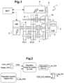
- a hybrid transmission architecture where the powertrain comprises a main electric machine and an auxiliary electric machine, called HSG, for “High Voltage starter Generator”, mechanically linked in rotation to the internal combustion engine, is well known, in particular by the example what does it give figure 1 .
- HSG auxiliary electric machine
- This auxiliary machine makes it possible to add a large number of functionalities to the transmission, particularly with regard to the speed of starting the internal combustion engine.
- the solid primary shaft 5 also carries a fixed primary coupling pinion 11 meshing with the auxiliary coupling fixed pinion 10 of the auxiliary shaft 8, ensuring the permanent passage of the movement on the auxiliary shaft 8.
- the internal combustion engine 2 linked to the solid primary shaft 5 is thus permanently connected to the machine auxiliary electric machine 4.
- the two motors respectively the internal combustion engine 2 and the auxiliary electric machine 4, rotate systematically at proportional speeds following the ratio formed by the gear chain 9, 10, 11.
- the engagement and disengagement of the gears is ensured by coupling systems controlled without a synchronizer, with dogs or flat teeth, also called “claws”, movable axially on a shaft.
- the clutches are driven in the direction of axially fixed speed pinions, rotating madly on their shaft.
- the engagement of the movable dogs on the pinions engages the shaft and the pinion, to transmit the torque to the wheels on the engaged transmission ratio.
- the transmission uses three dog coupling systems C1, C2, C3. It is a robotic type gearbox, that is to say that its operation is that of a manual gearbox, but the gear changes are carried out automatically, using a control system. actuation allowing the clutches to be engaged and disengaged.
- the gearbox combines the torque of the motor 2, the main electrical machine 3, and the auxiliary electrical machine 4 on the secondary shaft 7, in the direction of the vehicle wheels.
- the gear changes are carried out under the control of the three dog coupling systems C1, C2, C3, arranged respectively on the solid primary shaft 5, on the secondary shaft 7 and on the return shaft 8.
- the first coupling system called primary coupler C1, placed on the solid primary shaft 5, makes it possible to engage a short thermal transmission ratio (on the left) corresponding to the second reduction ratio of the transmission and to engage a thermal transmission ratio long (right) corresponding to the fourth reduction gear of the transmission.
- the second coupling system, called secondary coupler C2, placed on the secondary shaft 7, makes it possible to engage the two electric transmission ratios EV1 and EV2 of the main electric machine.
- the third coupling system called transfer coupler C3, placed on the auxiliary shaft 8, allows the torque of the auxiliary electric machine 4 to be transferred to the secondary shaft 7 (right), or to the hollow primary shaft 6 (to the left).
- a particular operating mode of this gearbox is what is called series hybrid mode.
- the main electric machine 3 is connected to the wheels via the electric gear EV1 or EV2.
- the internal combustion engine 2, coupled to the auxiliary electric machine 4, is kept in neutral, that is to say it does not transmit torque to the wheels, but rotates, which offers the possibility of providing power. couple to the internal combustion engine and thus recharge the battery (or directly power the main electric machine 3), via the auxiliary electric machine 4 coupled to the internal combustion engine.
- the internal combustion engine drives the auxiliary electrical machine which then operates as a generator and supplies electrical energy to the battery and possibly to the main electrical machine.
- the main electrical machine provides mechanical power to the wheels. Energy is therefore transmitted in series from the internal combustion engine, via the auxiliary electric machine, to the battery or to the main electric machine.
- the main electric machine 3 is therefore the only motor coupled to the wheels of the vehicle, via the electric ratio EV1 or EV2.
- EV1 or EV2 the electric ratio of this mode thus appears in the possibility of using the main electric machine 3 to drive the vehicle, while the auxiliary electric machine 4, driven by the internal combustion engine, operates as a generator. It is then possible to place the transmission at interesting efficiency points for the internal combustion engine, making it possible to achieve recharging power while regulating a target speed compatible with noise constraints (mainly avoiding excessively high speeds), and to turn the wheels at low speed, since it is the main electrical machine that turns the wheels.
- This mode is therefore particularly interesting at low speed when no gear allows the internal combustion engine to be engaged (because it would have too low a speed).
- the speed of the internal combustion engine is chosen by the regulation, so that it can be operated, even with the vehicle stationary, and recharge the battery. to power vehicle consumers or the main electrical machine, to ensure takeoff of the vehicle.
- the internal combustion engine and the auxiliary electric machine do not have the same torque production dynamics.
- the response of the auxiliary electric machine, which is electrically controlled will be much faster than that of the internal combustion engine.
- the speed regulation of the auxiliary electric machine calculates the torque to be applied to the auxiliary electric machine.
- the internal combustion engine is asked to produce power.
- the auxiliary electrical machine must be able to absorb all the power produced by the internal combustion engine, we deduce that the electrical power supplied to the HT network (high voltage as opposed to low 12V voltage from the on-board network) of the vehicle (to supply electrical energy to the battery and possibly the main electrical machine) will be equivalent to the power supplied by the internal combustion engine to the nearest efficiency.
- a problem which then arises is to achieve precise control of the power supplied by the internal combustion engine. In fact, the latter is rather imprecise in achieving the requested torque. It is therefore common to have up to several tens of Nm of error between the target torque requested from the motor and the torque actually achieved. For example, if the motor overachieves the requested torque, two scenarios can then arise. If the auxiliary electric machine/battery unit is capable of absorbing the excess power supplied by the internal combustion engine, then the regulation is designed to increase the recharging power of the auxiliary electric machine, so as to maintain the engine speed at its set value. The impact is then not significant, the charging power will simply be higher than what we wanted.
- a simple solution then consists of taking a margin in relation to the potential of the auxiliary electric machine/battery unit to calculate the power required from the internal combustion engine. For example, if the auxiliary electric machine/battery unit can only recharge 20kW, then by taking a 20% margin, no more than 16kW of power will be required from the internal combustion engine.
- this margin system does not work in the case where the battery can no longer tolerate charging power (tolerated charging power less than 5kW for example).
- This case can occur cold, typically below -15°C, where the batteries barely support more than a few kW of charging power.
- This scenario can also occur after a long charging period, because the battery will modulate its charging power.
- the main electric machine when lifting the foot and depressing the brake pedal, the main electric machine will recharge the battery, thus using the full recharge potential of the battery, leaving no recharge power available to the auxiliary electric machine. In all these cases, we observe a very low potential for charging power and the margin provided for the potential becomes ineffective.
- the invention aims to provide a method for controlling a hybrid powertrain of a motor vehicle overcoming the aforementioned drawbacks in the limit states of the series hybrid mode. More particularly, the invention aims to make it possible to compensate for torque over-realization errors of the internal combustion engine, in series hybrid mode of the transmission.
- the invention relates to a method for controlling a powertrain for a motor vehicle with hybrid electric transmission, comprising an internal combustion engine, a main electrical machine and an auxiliary electrical machine mechanically linked in rotation to the internal combustion engine , said two electric machines being connected to an electric storage battery of the vehicle, said method comprising, in a series hybrid transmission mode, where the main electric machine alone generates the mechanical power to the wheels of the vehicle and where the internal combustion engine drives the auxiliary electric machine operating as a generator to produce recharging power, a step of regulating the engine speed to a set value, where said motor is torque controlled on the basis of a torque set point to be applied to said electric machine auxiliary, said method being characterized in that it comprises a step of detecting a situation of saturation of the torque control of said auxiliary electric machine and, in the event of saturation, a step of correcting the torque requested from the combustion engine internal, so that the engine speed returns to its set value.
- the step of correcting the torque requested from the internal combustion engine is carried out as a function of regulating the torque margin remaining between the torque setpoint of said auxiliary electric machine and a maximum torque potential achievable by the electric machine auxiliary, in relation to a given minimum value of torque margin to be maintained, said regulation making it possible to guarantee said minimum torque margin value for said auxiliary electrical machine so as to ensure the stability of the regime.
- the regulation calculates a torque correction value of the internal combustion engine linked to the saturation of the auxiliary electrical machine, intended to correct a torque target requested from the internal combustion engine.
- the maximum torque potential achievable by the auxiliary electric machine corresponds to the maximum recharge power potential achievable by the auxiliary electric machine/battery unit.
- the step of correcting the torque requested from the internal combustion engine is triggered when the torque of the auxiliary electric machine approaches a saturation value.
- said saturation value corresponds to a maximum torque value achievable by said auxiliary electrical machine.
- the step of correcting the torque requested from the internal combustion engine is triggered when the internal combustion engine overachieves the requested torque.
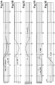
- the speed regulation of the series hybrid mode is designed to calculate a torque setpoint C_req_HSG to be applied to the auxiliary electric machine operating in generator mode to achieve a given recharging power, while regulating the speed to a setpoint value, while In parallel, the internal combustion engine 2 is asked to produce power according to a torque target Cible_ICE_basique, representing the recharge target.
- the speed regulation of the internal combustion engine/auxiliary electric machine block therefore consists of determining a torque setpoint to be applied to the auxiliary electric machine, and of controlling the internal combustion engine in parallel to produce the corresponding power on the basis of this torque reference.
- the invention aims to make it possible to better manage cases of saturation of the auxiliary electrical machine in series hybrid mode.
- the principle of the invention consists of adding a second regulation, in addition to the speed regulation, which is designed to regulate the Marge_HSG torque margin remaining between the torque setpoint sent to the auxiliary electric machine (calculated by the speed regulation) and the maximum torque potential achievable by the auxiliary electric machine.
- This maximum torque potential is obtained from the maximum recharge power potential achievable by the auxiliary electric machine/battery unit.
- This second regulation will therefore intervene only when it is detected that the torque of the auxiliary electric machine is approaching too close to its saturation limit value and will make it possible, in this case only, to reduce the torque setpoint of the combustion engine. internal so that the speed returns under control, that is to say to its set value.
- This second regulation is thus intended to act when the first regulation, i.e. the regulation in operation made by the auxiliary electrical machine, saturates.
- the control of the internal combustion engine in open loop is therefore carried out on the basis of the torque target Cible_ICE_basique, corresponding to the 10 Nm of torque requested. If the internal combustion engine does not over-achieve the requested torque, then the auxiliary electric machine is indeed capable of absorbing the power supplied by the internal combustion engine and the second regulation will not intervene.
- the auxiliary electric machine will reach saturation to absorb the unrequested additional power supplied by the internal combustion engine and the second regulation will then to intervene.
- This second regulation takes as input the remaining torque margin Marge_HSG of the auxiliary electrical machine taking into account the torque setpoint calculated by the C_req_HSG speed regulation, and will regulate the remaining torque margin so as to guarantee that there always remains a predetermined minimum value of torque margin Cmin_HSG for the auxiliary electrical machine to ensure speed stability.
- the minimum torque margin value Cmin_HSG makes it possible to define a target for regulating the torque margin of the auxiliary electrical machine, linked to the saturation of the auxiliary electrical machine.
- FIGS. 3A to 3E are graphs illustrating the evolution of the torques of the internal combustion engine and the auxiliary electric machine during the process of the invention, as well as the engine speed, under test conditions simulating a sudden loss of recharge potential on the battery side for the auxiliary electric machine, that is to say that the battery leaves, under these conditions, no recharging power available to the auxiliary electric machine. This is typically a case of lifting the foot, where the recharging power is then provided by the main electrical machine to carry out the driver's wishes, for example.
- This phenomenon is illustrated in the Figure 3E , which shows the curve of the charging potential on the P_BAT battery side, which quickly rises from substantially 35 kW of possible charging potential to 0 kW.
Landscapes
- Engineering & Computer Science (AREA)
- Mechanical Engineering (AREA)
- Transportation (AREA)
- Chemical & Material Sciences (AREA)
- Combustion & Propulsion (AREA)
- Power Engineering (AREA)
- Sustainable Energy (AREA)
- Life Sciences & Earth Sciences (AREA)
- Sustainable Development (AREA)
- Automation & Control Theory (AREA)
- General Engineering & Computer Science (AREA)
- Electric Propulsion And Braking For Vehicles (AREA)
- Hybrid Electric Vehicles (AREA)
- Control Of Vehicle Engines Or Engines For Specific Uses (AREA)
Claims (7)
- Verfahren zum Steuern eines Antriebsstrangs für ein Kraftfahrzeug mit Hybrid-Elektrogetriebe, umfassend einen Verbrennungsmotor (2), eine Hauptelektromaschine (3) und eine mit dem Verbrennungsmotor mechanisch drehfest verbundene Hilfselektromaschine (4), wobei die zwei elektrischen Maschinen mit einer elektrischen Speicherbatterie (BAT) des Fahrzeugs verbunden sind, wobei das Verfahren in einem seriellen Hybridübertragungsmodus, bei dem die elektrische Hauptmaschine (3) allein die mechanische Leistung für die Räder des Fahrzeugs erzeugt und bei dem der Verbrennungsmotor (2) die elektrische Hilfsmaschine (4) antreibt, die als Generator arbeitet, um Ladeleistung bereitzustellen, einen Schritt zum Regeln der Motordrehzahl auf einen Sollwert (R_req_ICE) umfasst, bei dem der Motor auf der Grundlage eines Drehmomentsollwerts (C_req_HSG) drehmomentgesteuert wird, der an die elektrische Hilfsmaschine angelegt werden soll, wobei das Verfahren dadurch gekennzeichnet ist, dass es einen Schritt zum Erkennen einer Sättigungssituation der Drehmomentsteuerung der elektrischen Hilfsmaschine und, im Falle einer Sättigung, einen Schritt zum Korrigieren des vom Verbrennungsmotor angeforderte Drehmoments umfasst, sodass die Motordrehzahl wieder auf ihren Sollwert zurückkehrt.
- Verfahren nach Anspruch 1, dadurch gekennzeichnet, dass der Schritt zum Korrigieren des vom Verbrennungsmotor angeforderten Drehmoments in Abhängigkeit von einer Regelung des verbleibenden Drehmomentspielraums zwischen dem Drehmomentsollwert der elektrischen Hilfsmaschine und einem maximalen Drehmomentpotential, das von der elektrischen Hilfsmaschine erreichbar ist, durchgeführt wird, relativ zu einem gegebenen Mindestwert des einzuhaltenden Drehmomentspielraums, wobei die Regelung es ermöglicht, den Mindestwert des Drehmomentspielraums für die elektrische Hilfsmaschine sicherzustellen, um die Stabilität der Drehzahl zu gewährleisten.
- Verfahren nach Anspruch 2, dadurch gekennzeichnet, dass die Regelung ausgehend vom Wert des minimalen Drehmomentspielraums einen Drehmomentkorrekturwert (C_cor_ICE) des Verbrennungsmotors berechnet, der mit der Sättigung der elektrischen Hilfsmaschine verknüpft ist, der dazu ausgelegt ist, ein vom Verbrennungsmotor angefordertes Drehmomentziel (Ziel_ICE_Basis) zu korrigieren.
- Verfahren nach Anspruch 2 oder 3, dadurch gekennzeichnet, dass das von der elektrischen Hilfsmaschine erreichbare maximale Drehmomentpotential dem von der Einheit der elektrischen Hilfsmaschine/Batterie maximal erreichbaren Ladeleistungspotential entspricht.
- Verfahren nach einem der vorstehenden Ansprüche,
dadurch gekennzeichnet, dass der Schritt zum Korrigieren des vom Verbrennungsmotor angeforderten Drehmoments dann ausgelöst wird, wenn sich das Drehmoment der elektrischen Hilfsmaschine einem Sättigungswert nähert. - Verfahren nach Anspruch 5, dadurch gekennzeichnet, dass der Sättigungswert einem von der elektrischen Hilfsmaschine maximal erreichbaren Drehmomentwert entspricht.
- Verfahren nach einem der vorstehenden Ansprüche,
dadurch gekennzeichnet, dass der Schritt zum Korrigieren des vom Verbrennungsmotor angeforderten Drehmoments dann ausgelöst wird, wenn der Verbrennungsmotor das angeforderte Drehmoment übersteigt.
Applications Claiming Priority (2)
| Application Number | Priority Date | Filing Date | Title |
|---|---|---|---|
| FR2005013A FR3110527B1 (fr) | 2020-05-19 | 2020-05-19 | Procédé de commande d’un groupe motopropulseur pour véhicule automobile à transmission électrique hybride |
| PCT/EP2021/062260 WO2021233704A1 (fr) | 2020-05-19 | 2021-05-10 | Procédé de commande d'un groupe motopropulseur pour véhicule automobile à transmission électrique hybride |
Publications (2)
| Publication Number | Publication Date |
|---|---|
| EP4153439A1 EP4153439A1 (de) | 2023-03-29 |
| EP4153439B1 true EP4153439B1 (de) | 2024-07-03 |
Family
ID=72266447
Family Applications (1)
| Application Number | Title | Priority Date | Filing Date |
|---|---|---|---|
| EP21725465.5A Active EP4153439B1 (de) | 2020-05-19 | 2021-05-10 | Verfahren zur steuerung einer antriebsstrangeinheit für ein kraftfahrzeug mit hybridem elektrischen getriebe |
Country Status (6)
| Country | Link |
|---|---|
| EP (1) | EP4153439B1 (de) |
| JP (1) | JP2023526201A (de) |
| KR (1) | KR102943237B1 (de) |
| CN (1) | CN115697741B (de) |
| FR (1) | FR3110527B1 (de) |
| WO (1) | WO2021233704A1 (de) |
Family Cites Families (9)
| Publication number | Priority date | Publication date | Assignee | Title |
|---|---|---|---|---|
| FR2791195B1 (fr) * | 1999-03-15 | 2001-05-18 | Renault | Systeme de commande d'un groupe generateur electrique |
| US6397963B1 (en) * | 2000-10-31 | 2002-06-04 | Ford Global Technologies, Inc. | Method and arrangement in a hybrid vehicle for maintaining a catalyst in an effective state |
| JP3783657B2 (ja) * | 2002-06-04 | 2006-06-07 | 日産自動車株式会社 | ハイブリッド車両の制御装置 |
| FR2918338B1 (fr) * | 2007-07-06 | 2009-10-30 | Renault Sas | Dispositif et procede d'assistance pour un vehicule. |
| FR2921037B1 (fr) * | 2007-09-18 | 2009-11-13 | Renault Sas | Systeme de commande pour la gestion de l'energie electrique transitant par un element de stockage dans un groupe motopropulseur hybride equipe d'une transmission infiniment variable |
| US9145133B2 (en) * | 2013-11-08 | 2015-09-29 | Ford Global Technologies, Llc | Method and system for selecting an engine operating point for a hybrid vehicle |
| KR101788190B1 (ko) * | 2016-04-08 | 2017-10-19 | 현대자동차주식회사 | 하이브리드 전기 자동차의 주행 모드 제어 방법 및 장치 |
| FR3067314B1 (fr) * | 2017-06-09 | 2019-06-21 | Renault S.A.S | Procede d'elaboration d'une consigne de couple aux machines electriques d'un groupe motopropulseur de vehicule et groupe motopropulseur de vehicule |
| MX2020006231A (es) * | 2017-12-15 | 2020-09-03 | Nissan Motor | Metodo de control y dispositivo de control para vehiculo hibrido. |
-
2020
- 2020-05-19 FR FR2005013A patent/FR3110527B1/fr active Active
-
2021
- 2021-05-10 KR KR1020227041342A patent/KR102943237B1/ko active Active
- 2021-05-10 CN CN202180036342.7A patent/CN115697741B/zh active Active
- 2021-05-10 WO PCT/EP2021/062260 patent/WO2021233704A1/fr not_active Ceased
- 2021-05-10 EP EP21725465.5A patent/EP4153439B1/de active Active
- 2021-05-10 JP JP2022568423A patent/JP2023526201A/ja not_active Ceased
Also Published As
| Publication number | Publication date |
|---|---|
| KR20230013246A (ko) | 2023-01-26 |
| WO2021233704A1 (fr) | 2021-11-25 |
| KR102943237B1 (ko) | 2026-03-26 |
| EP4153439A1 (de) | 2023-03-29 |
| JP2023526201A (ja) | 2023-06-21 |
| CN115697741B (zh) | 2026-03-31 |
| CN115697741A (zh) | 2023-02-03 |
| FR3110527B1 (fr) | 2022-06-10 |
| FR3110527A1 (fr) | 2021-11-26 |
Similar Documents
| Publication | Publication Date | Title |
|---|---|---|
| EP2885147B1 (de) | Verfahren zur begrenzung des drehmoments einer elektrischen maschine eines hybridfahrzeugs mit einer drehzahlregelungssystem | |
| FR2847638A1 (fr) | Systeme de commande de changement de rapport pour vehicule hybrides | |
| FR2909625A1 (fr) | Dispositif de commande de source de propulsion pour vehicule | |
| EP2928746A1 (de) | Verfahren zur steuerung von drehmomenten bei der inbetriebnahme des verbrennungsmotors eines hybridfahrzeugs zur umschaltung von einem elektrischen modus zu einem hybridmodus | |
| FR3023218A1 (fr) | Procede de commande de systeme de motorisation hybride, pour un vehicule hybride | |
| EP2928715B1 (de) | Verfahren zur steuerung von drehmomenten beim wechseln von gängen bei einem schaltgetriebe eines hybridfahrzeugs | |
| FR2992040A1 (fr) | Procede et dispositif de controle de la vitesse engagee d'une boite de vitesses automatisee de vehicule, en fonction d'une acceleration demandee par un systeme de controle de vitesse | |
| FR3072056A1 (fr) | Procede de pilotage d'un groupe motopropulseur hybride electrique | |
| EP3074257B1 (de) | Verfahren und system zum starten eines verbrennungsmotors | |
| EP4153439B1 (de) | Verfahren zur steuerung einer antriebsstrangeinheit für ein kraftfahrzeug mit hybridem elektrischen getriebe | |
| EP3672819B1 (de) | Steuerung der startzeiten eines kriechvorgangs durch einen verbrennungsmotor und eine nicht-thermische antriebsmaschine eines hybridfahrzeugs | |
| EP2996916B1 (de) | Verfahren zur steuerung einer krafteinheit mit einem verbrennungsmotor und einem automatikgetriebe | |
| FR2934526A1 (fr) | Systeme et procede de commande d'un groupe motopropulseur hybride | |
| FR2992041A1 (fr) | Procede et dispositif de controle de l'utilisation des moteurs electrique et thermique d'un vehicule hybride, en fonction d'une acceleration demandee par un systeme de controle de vitesse | |
| EP3710300A1 (de) | Verfahren zur steuerung einer eingriffsvorrichtung für eine elektrische maschine eines hybridfahrzeugs | |
| EP2920038B1 (de) | Verfahren und vorrichtung zur steuerung der drehmomente eines verbrennungsmotors und hilfsmotor (s) eines hybridfahrzeugs in gegenwart eines sollwertanstiegs | |
| FR3161642A1 (fr) | Procédé de commande pour un groupe motopropulseur hybride électrique | |
| EP2274189A1 (de) | System und verfahren zur steuerung des wechsels eines stufenlos variablen getriebes in einen rein elektrischen modus | |
| WO2013117844A1 (fr) | Procede et systeme de gestion semi-automatisee d'une traction hybride | |
| FR3122466A1 (fr) | Pilotage des embrayages d’une transmission DCT en phase de rampage | |
| FR3152265A1 (fr) | Procédé de pilotage d’une transmission DCT en récupération d’énergie | |
| EP3931055A1 (de) | Steuerung eines kraftfahrzeugantriebsstranges während der assistierten entschleunigung | |
| FR3003320A1 (fr) | Procede et dispositif de controle du pre-positionnement temporaire d'un embrayage d'une boite de vitesses robotisee d'un vehicule |
Legal Events
| Date | Code | Title | Description |
|---|---|---|---|
| STAA | Information on the status of an ep patent application or granted ep patent |
Free format text: STATUS: UNKNOWN |
|
| STAA | Information on the status of an ep patent application or granted ep patent |
Free format text: STATUS: THE INTERNATIONAL PUBLICATION HAS BEEN MADE |
|
| PUAI | Public reference made under article 153(3) epc to a published international application that has entered the european phase |
Free format text: ORIGINAL CODE: 0009012 |
|
| STAA | Information on the status of an ep patent application or granted ep patent |
Free format text: STATUS: REQUEST FOR EXAMINATION WAS MADE |
|
| 17P | Request for examination filed |
Effective date: 20221110 |
|
| AK | Designated contracting states |
Kind code of ref document: A1 Designated state(s): AL AT BE BG CH CY CZ DE DK EE ES FI FR GB GR HR HU IE IS IT LI LT LU LV MC MK MT NL NO PL PT RO RS SE SI SK SM TR |
|
| DAV | Request for validation of the european patent (deleted) | ||
| DAX | Request for extension of the european patent (deleted) | ||
| GRAP | Despatch of communication of intention to grant a patent |
Free format text: ORIGINAL CODE: EPIDOSNIGR1 |
|
| STAA | Information on the status of an ep patent application or granted ep patent |
Free format text: STATUS: GRANT OF PATENT IS INTENDED |
|
| INTG | Intention to grant announced |
Effective date: 20231222 |
|
| GRAS | Grant fee paid |
Free format text: ORIGINAL CODE: EPIDOSNIGR3 |
|
| GRAA | (expected) grant |
Free format text: ORIGINAL CODE: 0009210 |
|
| STAA | Information on the status of an ep patent application or granted ep patent |
Free format text: STATUS: THE PATENT HAS BEEN GRANTED |
|
| AK | Designated contracting states |
Kind code of ref document: B1 Designated state(s): AL AT BE BG CH CY CZ DE DK EE ES FI FR GB GR HR HU IE IS IT LI LT LU LV MC MK MT NL NO PL PT RO RS SE SI SK SM TR |
|
| REG | Reference to a national code |
Ref country code: CH Ref legal event code: EP |
|
| REG | Reference to a national code |
Ref country code: DE Ref legal event code: R096 Ref document number: 602021015171 Country of ref document: DE |
|
| REG | Reference to a national code |
Ref country code: LT Ref legal event code: MG9D |
|
| REG | Reference to a national code |
Ref country code: NL Ref legal event code: MP Effective date: 20240703 |
|
| PG25 | Lapsed in a contracting state [announced via postgrant information from national office to epo] |
Ref country code: PT Free format text: LAPSE BECAUSE OF FAILURE TO SUBMIT A TRANSLATION OF THE DESCRIPTION OR TO PAY THE FEE WITHIN THE PRESCRIBED TIME-LIMIT Effective date: 20241104 |
|
| REG | Reference to a national code |
Ref country code: AT Ref legal event code: MK05 Ref document number: 1699485 Country of ref document: AT Kind code of ref document: T Effective date: 20240703 |
|
| PG25 | Lapsed in a contracting state [announced via postgrant information from national office to epo] |
Ref country code: NL Free format text: LAPSE BECAUSE OF FAILURE TO SUBMIT A TRANSLATION OF THE DESCRIPTION OR TO PAY THE FEE WITHIN THE PRESCRIBED TIME-LIMIT Effective date: 20240703 |
|
| PG25 | Lapsed in a contracting state [announced via postgrant information from national office to epo] |
Ref country code: PT Free format text: LAPSE BECAUSE OF FAILURE TO SUBMIT A TRANSLATION OF THE DESCRIPTION OR TO PAY THE FEE WITHIN THE PRESCRIBED TIME-LIMIT Effective date: 20241104 Ref country code: NL Free format text: LAPSE BECAUSE OF FAILURE TO SUBMIT A TRANSLATION OF THE DESCRIPTION OR TO PAY THE FEE WITHIN THE PRESCRIBED TIME-LIMIT Effective date: 20240703 |
|
| PG25 | Lapsed in a contracting state [announced via postgrant information from national office to epo] |
Ref country code: NO Free format text: LAPSE BECAUSE OF FAILURE TO SUBMIT A TRANSLATION OF THE DESCRIPTION OR TO PAY THE FEE WITHIN THE PRESCRIBED TIME-LIMIT Effective date: 20241003 |
|
| PG25 | Lapsed in a contracting state [announced via postgrant information from national office to epo] |
Ref country code: FI Free format text: LAPSE BECAUSE OF FAILURE TO SUBMIT A TRANSLATION OF THE DESCRIPTION OR TO PAY THE FEE WITHIN THE PRESCRIBED TIME-LIMIT Effective date: 20240703 Ref country code: GR Free format text: LAPSE BECAUSE OF FAILURE TO SUBMIT A TRANSLATION OF THE DESCRIPTION OR TO PAY THE FEE WITHIN THE PRESCRIBED TIME-LIMIT Effective date: 20241004 Ref country code: PL Free format text: LAPSE BECAUSE OF FAILURE TO SUBMIT A TRANSLATION OF THE DESCRIPTION OR TO PAY THE FEE WITHIN THE PRESCRIBED TIME-LIMIT Effective date: 20240703 |
|
| PG25 | Lapsed in a contracting state [announced via postgrant information from national office to epo] |
Ref country code: BG Free format text: LAPSE BECAUSE OF FAILURE TO SUBMIT A TRANSLATION OF THE DESCRIPTION OR TO PAY THE FEE WITHIN THE PRESCRIBED TIME-LIMIT Effective date: 20240703 |
|
| PG25 | Lapsed in a contracting state [announced via postgrant information from national office to epo] |
Ref country code: LV Free format text: LAPSE BECAUSE OF FAILURE TO SUBMIT A TRANSLATION OF THE DESCRIPTION OR TO PAY THE FEE WITHIN THE PRESCRIBED TIME-LIMIT Effective date: 20240703 |
|
| PG25 | Lapsed in a contracting state [announced via postgrant information from national office to epo] |
Ref country code: IS Free format text: LAPSE BECAUSE OF FAILURE TO SUBMIT A TRANSLATION OF THE DESCRIPTION OR TO PAY THE FEE WITHIN THE PRESCRIBED TIME-LIMIT Effective date: 20241103 Ref country code: AT Free format text: LAPSE BECAUSE OF FAILURE TO SUBMIT A TRANSLATION OF THE DESCRIPTION OR TO PAY THE FEE WITHIN THE PRESCRIBED TIME-LIMIT Effective date: 20240703 |
|
| PG25 | Lapsed in a contracting state [announced via postgrant information from national office to epo] |
Ref country code: CZ Free format text: LAPSE BECAUSE OF FAILURE TO SUBMIT A TRANSLATION OF THE DESCRIPTION OR TO PAY THE FEE WITHIN THE PRESCRIBED TIME-LIMIT Effective date: 20240703 Ref country code: HR Free format text: LAPSE BECAUSE OF FAILURE TO SUBMIT A TRANSLATION OF THE DESCRIPTION OR TO PAY THE FEE WITHIN THE PRESCRIBED TIME-LIMIT Effective date: 20240703 |
|
| PG25 | Lapsed in a contracting state [announced via postgrant information from national office to epo] |
Ref country code: RS Free format text: LAPSE BECAUSE OF FAILURE TO SUBMIT A TRANSLATION OF THE DESCRIPTION OR TO PAY THE FEE WITHIN THE PRESCRIBED TIME-LIMIT Effective date: 20241003 Ref country code: ES Free format text: LAPSE BECAUSE OF FAILURE TO SUBMIT A TRANSLATION OF THE DESCRIPTION OR TO PAY THE FEE WITHIN THE PRESCRIBED TIME-LIMIT Effective date: 20240703 |
|
| PG25 | Lapsed in a contracting state [announced via postgrant information from national office to epo] |
Ref country code: RS Free format text: LAPSE BECAUSE OF FAILURE TO SUBMIT A TRANSLATION OF THE DESCRIPTION OR TO PAY THE FEE WITHIN THE PRESCRIBED TIME-LIMIT Effective date: 20241003 Ref country code: PL Free format text: LAPSE BECAUSE OF FAILURE TO SUBMIT A TRANSLATION OF THE DESCRIPTION OR TO PAY THE FEE WITHIN THE PRESCRIBED TIME-LIMIT Effective date: 20240703 Ref country code: NO Free format text: LAPSE BECAUSE OF FAILURE TO SUBMIT A TRANSLATION OF THE DESCRIPTION OR TO PAY THE FEE WITHIN THE PRESCRIBED TIME-LIMIT Effective date: 20241003 Ref country code: LV Free format text: LAPSE BECAUSE OF FAILURE TO SUBMIT A TRANSLATION OF THE DESCRIPTION OR TO PAY THE FEE WITHIN THE PRESCRIBED TIME-LIMIT Effective date: 20240703 Ref country code: IS Free format text: LAPSE BECAUSE OF FAILURE TO SUBMIT A TRANSLATION OF THE DESCRIPTION OR TO PAY THE FEE WITHIN THE PRESCRIBED TIME-LIMIT Effective date: 20241103 Ref country code: HR Free format text: LAPSE BECAUSE OF FAILURE TO SUBMIT A TRANSLATION OF THE DESCRIPTION OR TO PAY THE FEE WITHIN THE PRESCRIBED TIME-LIMIT Effective date: 20240703 Ref country code: GR Free format text: LAPSE BECAUSE OF FAILURE TO SUBMIT A TRANSLATION OF THE DESCRIPTION OR TO PAY THE FEE WITHIN THE PRESCRIBED TIME-LIMIT Effective date: 20241004 Ref country code: FI Free format text: LAPSE BECAUSE OF FAILURE TO SUBMIT A TRANSLATION OF THE DESCRIPTION OR TO PAY THE FEE WITHIN THE PRESCRIBED TIME-LIMIT Effective date: 20240703 Ref country code: ES Free format text: LAPSE BECAUSE OF FAILURE TO SUBMIT A TRANSLATION OF THE DESCRIPTION OR TO PAY THE FEE WITHIN THE PRESCRIBED TIME-LIMIT Effective date: 20240703 Ref country code: CZ Free format text: LAPSE BECAUSE OF FAILURE TO SUBMIT A TRANSLATION OF THE DESCRIPTION OR TO PAY THE FEE WITHIN THE PRESCRIBED TIME-LIMIT Effective date: 20240703 Ref country code: BG Free format text: LAPSE BECAUSE OF FAILURE TO SUBMIT A TRANSLATION OF THE DESCRIPTION OR TO PAY THE FEE WITHIN THE PRESCRIBED TIME-LIMIT Effective date: 20240703 Ref country code: AT Free format text: LAPSE BECAUSE OF FAILURE TO SUBMIT A TRANSLATION OF THE DESCRIPTION OR TO PAY THE FEE WITHIN THE PRESCRIBED TIME-LIMIT Effective date: 20240703 |
|
| REG | Reference to a national code |
Ref country code: DE Ref legal event code: R097 Ref document number: 602021015171 Country of ref document: DE |
|
| PG25 | Lapsed in a contracting state [announced via postgrant information from national office to epo] |
Ref country code: RO Free format text: LAPSE BECAUSE OF FAILURE TO SUBMIT A TRANSLATION OF THE DESCRIPTION OR TO PAY THE FEE WITHIN THE PRESCRIBED TIME-LIMIT Effective date: 20240703 Ref country code: DK Free format text: LAPSE BECAUSE OF FAILURE TO SUBMIT A TRANSLATION OF THE DESCRIPTION OR TO PAY THE FEE WITHIN THE PRESCRIBED TIME-LIMIT Effective date: 20240703 Ref country code: SM Free format text: LAPSE BECAUSE OF FAILURE TO SUBMIT A TRANSLATION OF THE DESCRIPTION OR TO PAY THE FEE WITHIN THE PRESCRIBED TIME-LIMIT Effective date: 20240703 |
|
| PG25 | Lapsed in a contracting state [announced via postgrant information from national office to epo] |
Ref country code: EE Free format text: LAPSE BECAUSE OF FAILURE TO SUBMIT A TRANSLATION OF THE DESCRIPTION OR TO PAY THE FEE WITHIN THE PRESCRIBED TIME-LIMIT Effective date: 20240703 |
|
| PG25 | Lapsed in a contracting state [announced via postgrant information from national office to epo] |
Ref country code: IT Free format text: LAPSE BECAUSE OF FAILURE TO SUBMIT A TRANSLATION OF THE DESCRIPTION OR TO PAY THE FEE WITHIN THE PRESCRIBED TIME-LIMIT Effective date: 20240703 Ref country code: SK Free format text: LAPSE BECAUSE OF FAILURE TO SUBMIT A TRANSLATION OF THE DESCRIPTION OR TO PAY THE FEE WITHIN THE PRESCRIBED TIME-LIMIT Effective date: 20240703 |
|
| PLBE | No opposition filed within time limit |
Free format text: ORIGINAL CODE: 0009261 |
|
| STAA | Information on the status of an ep patent application or granted ep patent |
Free format text: STATUS: NO OPPOSITION FILED WITHIN TIME LIMIT |
|
| 26N | No opposition filed |
Effective date: 20250404 |
|
| PGFP | Annual fee paid to national office [announced via postgrant information from national office to epo] |
Ref country code: DE Payment date: 20250521 Year of fee payment: 5 |
|
| PGFP | Annual fee paid to national office [announced via postgrant information from national office to epo] |
Ref country code: GB Payment date: 20250527 Year of fee payment: 5 |
|
| PGFP | Annual fee paid to national office [announced via postgrant information from national office to epo] |
Ref country code: FR Payment date: 20250528 Year of fee payment: 5 |
|
| PG25 | Lapsed in a contracting state [announced via postgrant information from national office to epo] |
Ref country code: SE Free format text: LAPSE BECAUSE OF FAILURE TO SUBMIT A TRANSLATION OF THE DESCRIPTION OR TO PAY THE FEE WITHIN THE PRESCRIBED TIME-LIMIT Effective date: 20240703 |
|
| REG | Reference to a national code |
Ref country code: CH Ref legal event code: H13 Free format text: ST27 STATUS EVENT CODE: U-0-0-H10-H13 (AS PROVIDED BY THE NATIONAL OFFICE) Effective date: 20251223 |
|
| PG25 | Lapsed in a contracting state [announced via postgrant information from national office to epo] |
Ref country code: LU Free format text: LAPSE BECAUSE OF NON-PAYMENT OF DUE FEES Effective date: 20250510 |
|
| PG25 | Lapsed in a contracting state [announced via postgrant information from national office to epo] |
Ref country code: CH Free format text: LAPSE BECAUSE OF NON-PAYMENT OF DUE FEES Effective date: 20250531 |
|
| REG | Reference to a national code |
Ref country code: BE Ref legal event code: MM Effective date: 20250531 |
|
| PG25 | Lapsed in a contracting state [announced via postgrant information from national office to epo] |
Ref country code: MC Free format text: LAPSE BECAUSE OF FAILURE TO SUBMIT A TRANSLATION OF THE DESCRIPTION OR TO PAY THE FEE WITHIN THE PRESCRIBED TIME-LIMIT Effective date: 20240703 |
|
| PG25 | Lapsed in a contracting state [announced via postgrant information from national office to epo] |
Ref country code: IE Free format text: LAPSE BECAUSE OF NON-PAYMENT OF DUE FEES Effective date: 20250510 |
|
| PG25 | Lapsed in a contracting state [announced via postgrant information from national office to epo] |
Ref country code: BE Free format text: LAPSE BECAUSE OF NON-PAYMENT OF DUE FEES Effective date: 20250531 |