EP4154698B1 - Procédé de détection du niveau du sol sur une surface à traiter par une machine de travail agricole - Google Patents
Procédé de détection du niveau du sol sur une surface à traiter par une machine de travail agricole Download PDFInfo
- Publication number
- EP4154698B1 EP4154698B1 EP22184000.2A EP22184000A EP4154698B1 EP 4154698 B1 EP4154698 B1 EP 4154698B1 EP 22184000 A EP22184000 A EP 22184000A EP 4154698 B1 EP4154698 B1 EP 4154698B1
- Authority
- EP
- European Patent Office
- Prior art keywords
- crop
- pulse
- working machine
- echo pulse
- field
- Prior art date
- Legal status (The legal status is an assumption and is not a legal conclusion. Google has not performed a legal analysis and makes no representation as to the accuracy of the status listed.)
- Active
Links
Images


Classifications
-
- A—HUMAN NECESSITIES
- A01—AGRICULTURE; FORESTRY; ANIMAL HUSBANDRY; HUNTING; TRAPPING; FISHING
- A01D—HARVESTING; MOWING
- A01D41/00—Combines, i.e. harvesters or mowers combined with threshing devices
- A01D41/12—Details of combines
- A01D41/127—Control or measuring arrangements specially adapted for combines
-
- G—PHYSICS
- G01—MEASURING; TESTING
- G01S—RADIO DIRECTION-FINDING; RADIO NAVIGATION; DETERMINING DISTANCE OR VELOCITY BY USE OF RADIO WAVES; LOCATING OR PRESENCE-DETECTING BY USE OF THE REFLECTION OR RERADIATION OF RADIO WAVES; ANALOGOUS ARRANGEMENTS USING OTHER WAVES
- G01S17/00—Systems using the reflection or reradiation of electromagnetic waves other than radio waves, e.g. lidar systems
- G01S17/02—Systems using the reflection of electromagnetic waves other than radio waves
- G01S17/06—Systems determining position data of a target
- G01S17/08—Systems determining position data of a target for measuring distance only
- G01S17/10—Systems determining position data of a target for measuring distance only using transmission of interrupted, pulse-modulated waves
-
- G—PHYSICS
- G01—MEASURING; TESTING
- G01S—RADIO DIRECTION-FINDING; RADIO NAVIGATION; DETERMINING DISTANCE OR VELOCITY BY USE OF RADIO WAVES; LOCATING OR PRESENCE-DETECTING BY USE OF THE REFLECTION OR RERADIATION OF RADIO WAVES; ANALOGOUS ARRANGEMENTS USING OTHER WAVES
- G01S17/00—Systems using the reflection or reradiation of electromagnetic waves other than radio waves, e.g. lidar systems
- G01S17/02—Systems using the reflection of electromagnetic waves other than radio waves
- G01S17/06—Systems determining position data of a target
- G01S17/42—Simultaneous measurement of distance and other co-ordinates
-
- G—PHYSICS
- G01—MEASURING; TESTING
- G01S—RADIO DIRECTION-FINDING; RADIO NAVIGATION; DETERMINING DISTANCE OR VELOCITY BY USE OF RADIO WAVES; LOCATING OR PRESENCE-DETECTING BY USE OF THE REFLECTION OR RERADIATION OF RADIO WAVES; ANALOGOUS ARRANGEMENTS USING OTHER WAVES
- G01S17/00—Systems using the reflection or reradiation of electromagnetic waves other than radio waves, e.g. lidar systems
- G01S17/88—Lidar systems specially adapted for specific applications
-
- G—PHYSICS
- G01—MEASURING; TESTING
- G01S—RADIO DIRECTION-FINDING; RADIO NAVIGATION; DETERMINING DISTANCE OR VELOCITY BY USE OF RADIO WAVES; LOCATING OR PRESENCE-DETECTING BY USE OF THE REFLECTION OR RERADIATION OF RADIO WAVES; ANALOGOUS ARRANGEMENTS USING OTHER WAVES
- G01S7/00—Details of systems according to groups G01S13/00, G01S15/00, G01S17/00
- G01S7/48—Details of systems according to groups G01S13/00, G01S15/00, G01S17/00 of systems according to group G01S17/00
- G01S7/4802—Details of systems according to groups G01S13/00, G01S15/00, G01S17/00 of systems according to group G01S17/00 using analysis of echo signal for target characterisation; Target signature; Target cross-section
-
- G—PHYSICS
- G01—MEASURING; TESTING
- G01S—RADIO DIRECTION-FINDING; RADIO NAVIGATION; DETERMINING DISTANCE OR VELOCITY BY USE OF RADIO WAVES; LOCATING OR PRESENCE-DETECTING BY USE OF THE REFLECTION OR RERADIATION OF RADIO WAVES; ANALOGOUS ARRANGEMENTS USING OTHER WAVES
- G01S7/00—Details of systems according to groups G01S13/00, G01S15/00, G01S17/00
- G01S7/48—Details of systems according to groups G01S13/00, G01S15/00, G01S17/00 of systems according to group G01S17/00
- G01S7/4808—Evaluating distance, position or velocity data
Definitions
- the present invention relates to a method for detecting the ground level on a surface to be worked by an agricultural working machine according to the preamble of claim 1. Furthermore, the present invention relates to an agricultural working machine for carrying out such a method according to claim 13.
- the determination of the crop height of a field using an optical sensor arrangement arranged on an agricultural machine, which determines distances using the time of flight method, is carried out using a static transformation related to the mounting position of the sensor arrangement.
- the sensor arrangement is usually arranged at the highest point of the machine, the cabin roof.
- the crop height is determined from this point on the sensor arrangement, from which electromagnetic transmission beams are emitted and reflected transmission beams are received.
- This type of determination of the crop height is subject to errors due to the lack of inclusion of the ground contour in the area observed by the sensor arrangement.
- a wavy ground structure that deviates from a uniform, flat ground contour leads to different crop heights. If there is a cutting edge or a driving lane, this effect can be slightly compensated for by ground level detection next to the field, i.e. in the area of the cutting edge or the driving lane, but not almost completely offset.
- the invention is therefore based on the object of developing a method of the type mentioned at the outset, by means of which the detection of the ground level is improved and thus the determination of the stand height becomes more precise.
- a method for detecting the ground level on an area to be worked by an agricultural work machine comprising a sensor arrangement by means of which transmission pulses from electromagnetic transmission beams are periodically emitted in at least one transmission direction onto the area to be worked, wherein the transmission pulses are reflected by a field and soil as reflection surfaces and received as echo pulses by the sensor arrangement and transmitted to a control unit of the work machine for evaluation, wherein for at least some of the transmission pulses emitted by the sensor arrangement designed as a laser scanner, different partial beams of one and the same transmission beam are reflected with a time offset from one another by reflection surfaces located in the respective transmission direction, so that the resulting echo pulse in each case is composed of correspondingly time-offset partial echo pulses.
- the ground level and/or a crop height of the field crop is determined by means of the control unit based on a pulse width within the resulting echo pulse and/or a pulse shape of the resulting echo pulse as well as a runtime-based distance determination of a distance value to the respective reflection surface.
- the fundamental idea is that by processing and evaluating the temporal signal shape of the echo pulses provided by the sensor arrangement designed as a laser scanner, a distinction is made between the crop and the ground as reflection surfaces.
- the ground level of the ground is detected as a reflection surface on which the crop to be harvested is located.
- the detection of the ground level on which the crop to be harvested is located enables a more precise determination of the actual crop height.
- the method according to the invention determines the respective ground level that occurs at the location where the crop is located whose crop height is being determined.
- the processing and evaluating the temporal signal shape of the echo pulses provided by the sensor arrangement designed as a laser scanner it is possible to distinguish between plants of different crop types. Depending on the crop type grown on an area to be worked, the respective crop height differs significantly.
- the method should be carried out depending on the crop type. In a field of corn, the distance between the ridge line of the crop and the ground is greater than, for example, in field of rapeseed or wheat.
- the reference curves can be stored in a memory unit of the control unit so that they can be retrieved.
- the reference curves are retrieved from an external data source.
- a variance, a standard deviation or a quantile, in particular a 10% quantile, can be used as a measure of dispersion in order to distinguish between crop types in the vicinity of the working machine.
- the differentiation between different crop types can be carried out based on the pulse width relative to a predetermined threshold value for an accumulation of measured values in a spatially limited segment within the field.
- the impact on the field crop can be determined based on a first rising edge of the respective resulting echo pulse and the impact on the ground can be determined based on a last falling edge of the resulting echo pulse.
- the crop height and the position of the ground level can be determined based on a time offset between the first rising edge and the last falling edge of the respective resulting echo pulse for an accumulation of measured values in a segment within the field crop.
- At least one instruction can be generated by the control unit to influence the operation of the work machine.
- the, in particular optional, detected crop height can be used to generate an instruction by the control unit that influences the operation of the work machine.
- the detection can be used for predictive height control of an attachment mounted on the work machine.
- the detection of the ground level can be used to control the cutting height of a cutting unit as an attachment of the work machine.
- the detection of the ground level can also be used to set or adjust a driving speed of the work machine.
- At least one instruction can be a specification and/or a selection of initial operating parameters for at least one working unit of the agricultural working machine.
- the at least one working unit can be an attachment or an attachment of a working machine designed as a self-propelled harvester or as a tractor.
- the reflection intensity of the respective resulting echo pulse, the wavelength and/or ambient light conditions can be determined by the laser scanner.
- the laser scanner can be set up to provide signals that enable an evaluation of the reflection intensity, existing ambient light conditions and/or the wavelength of the reflected transmission pulses in addition to the pulse width and/or the pulse shape, i.e. the temporal signal shape of the echo pulses.
- the surface color and/or the surface roughness of the reflection surfaces can be determined by means of the reflection intensity.
- the evaluation of the wavelength can also be used to determine the surface color and/or the surface roughness of the reflection surfaces.
- the composition of the reflection surfaces can be deduced from the wavelength of the reflected transmission pulses. This allows the determination of the type and location of the reflection surfaces to be further improved or refined.
- At least one additional optical sensor arrangement other than a laser scanner can be used to classify the crop type and/or foreign growth. Incorporating an additional optical sensor arrangement that is not designed as a laser scanner can help improve the analysis process when classifying the crop type.
- a camera can be provided as an optical sensor arrangement that generates images in the visible spectral range.
- a camera can be provided as an optical sensor arrangement that generates images in the near-infrared range.
- statistical or adaptive threshold methods or non-analytical methods can be used to analyze the respective resulting echo pulse.
- this include the Gaussian elimination method, support vector machine or artificial neural networks, by means of which a classification can be carried out.
- an agricultural working machine in particular a self-propelled harvesting machine or a tractor, is claimed for carrying out the proposed method as such.
- the laser scanner can be designed as a solid-state LiDAR, a Geiger-mode LiDAR, a scanning LiDAR or a single photon LiDAR.
- These LiDAR sensors are characterized by a high resolution, which improves the unambiguity of the assignment of the temporal signal shape of the echo pulses, for example by means of classic static or adaptive threshold methods or artificial neural networks.
- the in Fig. 1 The proposed work machine 1 shown, which is designed as a self-propelled harvesting machine, is used to work an agricultural area 25, here the harvesting of a field 2 on the area 25, which consists of a plurality of plants 3.
- the plants 3 of the field 2 are located on a field floor 4, as also shown in the illustration Fig. 1
- the working machine 1 can also be designed as a tractor with an attached or towed attachment.
- the field crop 2 is located in front of the working machine 1 in the direction of travel 5 of the working machine 1. Seen from the working machine 1, the frontmost plants 3a and the plants 3b inside the crop exist.
- the work machine 1 has a control unit 6 and a sensor arrangement 7, wherein by means of the sensor arrangement 7, transmission pulses 8 from electromagnetic transmission beams are periodically transmitted to the field 2 in at least one transmission direction 10.
- the transmission pulses 8 are reflected by the field 2 or the plants 3 as well as by the underlying soil 4 and are received as echo pulses 11 by the sensor arrangement 7.
- the plants 3 and the soil 4 form reflection surfaces RF.
- FIG. 1 A summary of the Fig. 1 and Fig. 2 shows that for at least some of the transmission pulses 8, different partial beams 12, 13 are reflected from plants 3a, 3b of the field 2 lying one behind the other in the respective transmission direction 10 with a time delay.
- the reason for this is that the partial beam 13 in Fig. 1a ) has to travel an additional path, namely twice the path ⁇ E, compared to the partial beam 12.
- the time offset is calculated by dividing the additional path by the propagation speed of the transmitted beam 9.
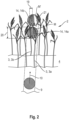
- Fig. 2 shows that the transmission beam 9 on the plant 3a is assigned a measuring spot M which is defined by the beam cross-section of the transmission beam 9.
- the plants 3 of the field 2 are here and preferably equipped with ears 14, wherein the ear 14a of the front plant 3a causes the reflection of the first partial beam 12, while the ear 14b of the rear plant 3b causes the reflection of a second partial beam 13.
- the representation of the transmission beam 9 and the partial beams 12, 13 in the drawing is an idealized state.
- a large number of partial beams 12, 13 usually result from one and the same transmission beam 9, to which the proposed basic principle can be applied analogously.
- all statements regarding the partial beams 12, 13 apply accordingly to all other partial beams that may occur.
- Fig. 2 shows that the beam cross-section of the transmission beam 9 must have a certain minimum extension in order to avoid the proposed multiple reflection of the transmission beam 9.
- the transmission beam 9 forms a rounded beam cross-section at the frontmost plants 3a in relation to the respective transmission direction.
- the measuring spot is preferably designed such that the transmission beam 9 can radiate past the relevant ear 14.
- the plants 3 form elongated ears 14 with a mean width 19, wherein the transmission beam 9 on the ears 14 of the plants 3a that are at the front in relation to the respective transmission direction 10 is assigned a measuring spot M due to its beam cross-section, the diameter 20 of which is larger in at least one direction, in particular at least twice as large, than the width 19 of the ears 14.
- Fig. 2 indicated schematically.
- Fig. 2 further shows that the measuring spot M' forms an excluded area 21 in the area of the plant 3b inside the stand, which results from the reflection of the partial beam 12, i.e. from the resulting radiation.
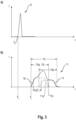
- Fig. 3a first the transmission pulse 8, which is sent by the sensor arrangement 7 in a transmission direction 11 to the field 2.
- the transmitted pulse 8 is represented by its light power I over time t.
- the representation in Fig. 3b shows a resulting echo pulse 11 of one of the plants 3, which is assigned to the transmission pulse 8.
- a corresponding representation of the resulting echo pulse 11 can be found in Fig. 3b ).
- the resulting echo pulse 11 is composed of correspondingly time-shifted partial echo pulses 11a, 11b.
- the time offset ⁇ T V corresponds to the above-mentioned time that the transmission beam 9 needs to travel the distance ⁇ E twice.
- From the Fig. 3b ) shows that the two partial echo pulses 11a, 11b merge into one another in the time domain.
- the partial echo pulses 11a, 11b are separated from one another in the time domain.
- a summary of the Fig. 1 , Fig. 2 and Fig. 3 shows that the distance ⁇ E, which is also referred to as the "penetration depth" here, can provide information about the stock density.
- the interesting fact here is that the penetration depth ⁇ E can be derived from the time offset ⁇ T V.
- a value for the stock density is determined based on a temporal relationship within the resulting echo pulse 11.
- the above temporal relationship is the above-mentioned time offset ⁇ T V between two partial echo pulses 11a, 11b, here between the first partial echo pulse 11a and the last partial echo pulse 11b, which are assigned to a transmission pulse 8.
- Fig. 3b shows that the time offset ⁇ T V can be derived to a certain extent from the resulting echo pulse 11.
- the time offset ⁇ T V is determined from a pulse width 15 of the resulting echo pulse 11, wherein the pulse width 15 is defined by the time interval between the first rising pulse edge 16 and the last falling pulse edge 17 of the resulting echo pulse 11.
- the time offset ⁇ T V is determined by subtracting a standardization width 18 from the pulse width 15, wherein the standardization width 18 is preferably defined by a pulse width 15a of the resulting echo pulse 11a, which would result from an assumed single reflection of the transmitted beam 9 on a plant 3a of the field 2.
- the standardization width 18 is therefore the pulse width 15a of the first partial echo pulse 11a.
- the pulse widths 15a, 15b of the two partial echo pulses 11a, 11b are identical to one another.
- the value for the stand density can generally be determined from the penetration depth ⁇ E.
- the value for the stand density is determined by forming the reciprocal of the penetration depth ⁇ E of the transmission beam 9 into the field stand 2 and that the penetration depth ⁇ E is determined from the product of the time offset ⁇ T V with the propagation speed and, if necessary, with a standardization factor. This reciprocal is then multiplied by a proportionality factor in order to arrive at the desired value for the stand density depending on the definition of the stand density.
- the electromagnetic beams are optical beams, in particular laser beams, whose transmission direction 10 can be adjusted by means of the control unit 6.
- the sensor arrangement 7 is a laser scanner 7a, which scans the field 2 or the area 25 in horizontally aligned lines.
- the inclination angle ⁇ of the transmission beam 9 can be adjusted around the horizontal and the scanning angle ⁇ around the vertical by means of the control arrangement 6.
- the sensor arrangement 7 is preferably designed as an optical distance sensor, wherein a distance value 22 between the sensor arrangement 7 and the respective reflecting plant 3a is determined by means of the sensor arrangement 7 from the time interval between the transmission time Ts of a transmission pulse 8 and the reception time T E of the associated echo pulse 11.
- the sensor arrangement 7 is preferably a time-of-flight sensor arrangement.
- the transmission direction 10 of the sensor arrangement 7 is continuously modified in the horizontal direction and/or in the vertical direction by means of the control unit 6.
- a crop height 23 is determined by means of the control unit 6 from the distance values and/or the values for the crop density.
- a line-by-line scanning of the field crop 2 is provided, with the angle of inclination ⁇ being chosen to be increasingly flatter.
- the position of a lateral stand edge 24 is determined from the distance values 22 and/or the values for the stand density by means of the control unit 6. This can also be accomplished by the automated detection of a sudden change in the relevant values.
- control unit 6 determines the position of a obstacle is determined. This determination can also be traced back to the automated recording of a sudden change in the relevant values.
- the soil 4 on which the field 2 is located forms a reflection surface RF for the respective transmission beam 9.
- the generalized representation in Fig. 4 a) shows two separate partial echo pulses E1, E2 and Fig. 4 b) shows two superimposed partial echo pulses E1, E2.
- the partial echo pulse E1 results from the reflection of the transmitted beam 9 on one of the plants 3 and the partial echo pulse E2 results from the reflection of the transmitted beam 9 on the ground 4.
- the resulting echo pulse 11 is composed of the partial echo pulses E1 and E2.
- 26 denotes a first rising edge of the reflected partial echo pulse E1 and 27 denotes a last falling edge of the reflected partial echo pulse E2.
- the first rising edge 26 of the partial echo pulse E1 marks the impact of the transmission beam 9 on the plants 3 of the field 2 and the last falling edge 27 of the partial echo pulse E2 marks the corresponding ground level.
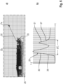
- Fig. 5 a) is an example of a cross-section of height values of a field 2a of a maize field and in Fig. 5 b) an exemplary echo pulse shape 28 of a field reflection of corn plants and a ground reflection of the soil 4 is shown as the respective reflection surface RF.
- Fig. 5 a) only the position of the laser scanner 7a arranged on the working machine 1 is indicated and only one emitted transmission beam 9 is shown as an example, which first hits the field 2a consisting of the maize plants and then the ground 4 and is partially reflected with a time delay in each case.
- the resulting echo pulse curves 30, 31 in the case of maize plants as field crop 2a, where the echo pulse curve 30 corresponds to the field crop reflection of the maize plants and the echo pulse curve 31 corresponds to the ground reflection, are shown as examples in Fig. 5 b) Due to the smaller distance between the ridge line of the field crop 2a and the laser scanner 7a arranged on the working machine 1 compared to other crop types, the partial echo pulses E1 of the maize plants are detected first and, with a significant time offset due to the crop height 23, then the partial echo pulses E2 of the ground reflection are detected.
- a first distance 32 between the laser scanner 7a and the ridge line of the field 2a is the distance to be covered by the transmission pulse 8 and the reflected partial echo pulse E1
- a second distance 33 between the ridge line and the field soil 4 is the additional distance that the transmission pulse 8 and the partial echo pulse E2 reflected from the soil 4 have to cover.
- the resulting time interval of the partial echo pulses E1, E2 enables a clear distinction to be made between the field 2a and the soil 4 on the one hand and, due to the pulse shape 28, an identification of the crop type of the plants within the field 2a, here the corn plants, using at least one reference curve specific to the corn crop type.
- the first rising flank 26 and the last falling flank 27 are identified as examples, from whose time offset ⁇ T F statements are made about the extent of the plant population 2a or the population height 23 and the position of the ground level.
- Fig. 6 a) is an example of a cross-section of height values of a field stand 2b of a rapeseed field and in Fig. 6 b) An example of an echo pulse shape 29 of a field reflection of rapeseed plants and a ground reflection is shown.
- Fig. 5 a) also, is in Fig. 6 a) only the position of the laser scanner 7a arranged on the working machine 1 is indicated and only one emitted transmission beam 9 is shown as an example, which first hits the field 2b consisting of the rapeseed plants and then the ground 4 and is partially reflected with a time delay in each case.
- the field stand 2b consisting of rapeseed plants has a lower stand height 23 than the field stand 2a consisting of maize plants, so that the difference between the first distance 32 and the second distance 33 and the associated signal propagation times in relation to the field stand 2a consisting of maize plants is considerably is lower. Accordingly, the field 2b consisting of rapeseed plants has a different echo pulse shape 29 than the field 2a consisting of maize plants.
- the first rising flank 26 and the last falling flank 27 are identified as examples, from whose time offset ⁇ T F statements are made about the extent of the plant population 2b or the population height 23 and the position of the ground level.
- control unit 6 can also be set up for image processing and image evaluation.
- the laser scanner 7a can be designed as a solid-state LiDAR, a Geiger-mode LiDAR, a scanning LiDAR or a single photon LiDAR. Different information contained in the LiDAR sensor signals is used for evaluation and classification. For example, a point cloud generated by the laser scanner 7a can be evaluated for the classification of geometric environmental and object properties. The evaluation of the amplitude or intensity of the resulting echo pulse 30, 31 can enable a determination of the surface color and/or surface roughness of the reflection surfaces RF. The detection of surface and/or object and/or environmental structures can be influenced by the ambient light.
- the influence of the ambient light can thus be taken into account when evaluating the LiDAR sensor signals in order to avoid distortions when classifying the surface and/or object and/or environmental structures of the reflection surfaces RF.
- the evaluation of the temporal signal shape or waveform of the pulse shapes 28 can be used to determine the surface and/or internal object structure.
- the evaluation of the wavelength of the transmitted transmission pulse 8 can be used to determine a surface color and/or a surface roughness and/or a composition of the reflection surfaces RF.
- the different information contained in the LiDAR sensor signals listed above can be partially evaluated with the same goal, e.g. determining the surface structure, surface color or surface roughness.
- At least one additional optical sensor arrangement can be used to classify the reflection surface RF as well as the type of crop and/or the foreign growth. Incorporating an additional optical sensor arrangement that is not designed as a laser scanner can help improve the analysis process during classification.
- a camera can be provided as an additional optical sensor arrangement that generates images in the visible spectral range.
- a camera can be provided as an additional optical sensor arrangement that generates images in the near-infrared range.
Landscapes
- Engineering & Computer Science (AREA)
- Physics & Mathematics (AREA)
- Computer Networks & Wireless Communication (AREA)
- General Physics & Mathematics (AREA)
- Radar, Positioning & Navigation (AREA)
- Remote Sensing (AREA)
- Electromagnetism (AREA)
- Life Sciences & Earth Sciences (AREA)
- Environmental Sciences (AREA)
- Optical Radar Systems And Details Thereof (AREA)
Claims (14)
- Procédé de détection du niveau du sol sur une surface (25) devant être traitée par une machine de travail agricole (1), la machine de travail (1) comprenant un dispositif à capteur (7) qui émet de manière périodique des impulsions d'émission (8) à partir de faisceaux d'émission (9) électromagnétiques, dans au moins une direction d'émission (10), sur la surface (25) à traiter, les impulsions d'émission (8) étant réfléchies par une culture de champ (2, 2a, 2b) et un sol (4), en tant que surfaces de réflexion (RF), et étant reçues en tant qu'impulsions écho (11) par le dispositif à capteur (7) et transmises à une unité de commande (6) de la machine de travail (1), en vue de l'évaluation, sachant que des faisceaux partiels (12, 13) différents d'un même faisceau d'émission (9) sont réfléchis avec un décalage réciproque dans le temps par des surfaces de réflexion (RF) se situant dans la direction d'émission (10) respective, pour au moins une partie des impulsions d'émission (8) émises par le dispositif à capteur (7) réalisé sous forme de scanner au laser (33), de sorte que l'impulsion écho (11) résultante respective se compose d'impulsions écho partielles (11a, 11b, E1, E2) présentant un décalage correspondant dans le temps, l'unité de commande (6) permettant de déterminer le niveau du sol et/ou une hauteur de culture (23), sur la base d'une largeur d'impulsion (ΔTF) à l'intérieur de l'impulsion écho (11) résultante et/ou d'une forme d'impulsion (28, 29) de l'impulsion écho (11) résultante, ainsi que d'une détermination de distance, fondée sur le temps de parcours, d'une valeur de distance (32, 33) par rapport à la surface de réflexion (RF) correspondante.
- Procédé selon la revendication 1, caractérisé en ce que le traitement et l'évaluation de la forme de signal temporelle des impulsions écho fournies par le dispositif à capteur (7) réalisé comme scanner au laser (7a), permettent de distinguer entre des plantes de différentes cultures.
- Procédé selon la revendication 2, caractérisé en ce qu'une distinction entre des types de cultures différents de la végétation du champ (2, 2a, 2b) est réalisée par une comparaison avec des courbes de référence, à l'aide d'un degré de dispersion de la hauteur de réflexion et/ou de la signature de la forme d'impulsion (28, 29).
- Procédé selon la revendication 3, caractérisé en ce que l'on utilise comme degré de dispersion une variance, un écart standard ou un quantile.
- Procédé selon la revendication 3 ou 4, caractérisé en ce que la distinction entre des types de cultures différents de la végétation du champ (2, 2a, 2b) est réalisée à l'aide de la largeur d'impulsion (15) rapportée à une valeur seuil prédéfinie, pour une accumulation de valeurs mesurées dans un segment délimité dans l'espace à l'intérieur de la végétation du champ (2, 2a, 2b).
- Procédé selon une des revendications précédentes, caractérisé en ce que l'on détermine l'impact sur la végétation du champ (2, 2a, 2b) à l'aide d'un premier flanc ascendant (26) de l'impulsion écho (11) résultante respective, et l'impact sur le sol (4) à l'aide d'un dernier flanc descendant (27) de l'impulsion écho (11) résultante.
- Procédé selon la revendication 6, caractérisé en ce que l'on détermine la hauteur de culture (23) et la position du niveau du sol à l'aide d'un décalage de temps (ΔTy) entre le premier flanc ascendant (26) et le dernier flanc descendant (27) de l'impulsion écho (11) résultante respective, pour une accumulation de valeurs mesurées dans un segment à l'intérieur de la végétation du champ (2, 2a, 2b).
- Procédé selon une des revendications précédentes, caractérisé en ce que, sur la base de la détection au moins du niveau du sol, au moins une instruction d'action est générée par l'unité de commande (6) pour influencer le fonctionnement de la machine de travail (1).
- Procédé selon la revendication 8, caractérisé en ce que l'on exécute, en tant qu'instruction d'action, au nombre d'au moins une, une prédéfinition et/ou une sélection de paramètres de fonctionnement initiaux pour au moins un équipement de travail de la machine agricole (1).
- Procédé selon une des revendications précédentes, caractérisé en ce que l'intensité de réflexion de l'impulsion écho (11) respective, la longueur d'onde et/ou les conditions lumineuses ambiantes sont déterminées par le scanner au laser (7a).
- Procédé selon une des revendications précédentes, caractérisé en ce que l'on utilise au moins un dispositif à capteur optique supplémentaire, différent d'un scanner au laser (7a), pour la classification du type de culture et/ou d'une végétation étrangère.
- Procédé selon une des revendications précédentes, caractérisé en ce que l'on utilise pour l'analyse de l'impulsion écho (11) résultante respective, des procédés à valeur seuil statistiques ou adaptatifs ou des procédés non analytiques.
- Machine de travail agricole (1), notamment machine de récolte automotrice ou tracteur, qui est dotée des moyens techniques pour la mise en œuvre d'un procédé selon une des revendications précédentes.
- Machine de travail agricole (1) selon la revendication 13, caractérisée en ce que le scanner au laser (7a) est réalisé comme LiDAR à l'état solide, comme Lidar à mode Geiger, comme LiDAR à balayage ou comme LiDAR à photon unique.
Applications Claiming Priority (1)
| Application Number | Priority Date | Filing Date | Title |
|---|---|---|---|
| DE102021124481.1A DE102021124481A1 (de) | 2021-09-22 | 2021-09-22 | Verfahren zur Detektion des Bodenniveaus auf einer von einer landwirtschaftlichen Arbeitsmaschine zu bearbeitenden Fläche |
Publications (2)
| Publication Number | Publication Date |
|---|---|
| EP4154698A1 EP4154698A1 (fr) | 2023-03-29 |
| EP4154698B1 true EP4154698B1 (fr) | 2025-02-19 |
Family
ID=82404101
Family Applications (1)
| Application Number | Title | Priority Date | Filing Date |
|---|---|---|---|
| EP22184000.2A Active EP4154698B1 (fr) | 2021-09-22 | 2022-07-11 | Procédé de détection du niveau du sol sur une surface à traiter par une machine de travail agricole |
Country Status (2)
| Country | Link |
|---|---|
| EP (1) | EP4154698B1 (fr) |
| DE (1) | DE102021124481A1 (fr) |
Family Cites Families (5)
| Publication number | Priority date | Publication date | Assignee | Title |
|---|---|---|---|---|
| DE102008043716B4 (de) * | 2008-11-13 | 2012-06-21 | Deere & Company | Vorrichtung und Verfahren zur Erfassung der Bestandsdichte von Pflanzen auf einem Feld |
| DE102011017621A1 (de) * | 2011-04-27 | 2012-10-31 | Deere & Company | Anordnung und Verfahren zur Erfassung der Menge von Pflanzen auf einem Feld |
| DE102011085380A1 (de) * | 2011-10-28 | 2013-05-02 | Deere & Company | Anordnung und Verfahren zur vorausschauenden Untersuchung von mit einer Erntemaschine aufzunehmenden Pflanzen |
| DE102018104207A1 (de) * | 2018-02-23 | 2019-08-29 | Claas Selbstfahrende Erntemaschinen Gmbh | Selbstfahrende Erntemaschine |
| DE102018104205A1 (de) * | 2018-02-23 | 2019-08-29 | Claas Selbstfahrende Erntemaschinen Gmbh | Verfahren zur Ermittlung der Bestandsdichte eines Feldbestands |
-
2021
- 2021-09-22 DE DE102021124481.1A patent/DE102021124481A1/de active Pending
-
2022
- 2022-07-11 EP EP22184000.2A patent/EP4154698B1/fr active Active
Also Published As
| Publication number | Publication date |
|---|---|
| DE102021124481A1 (de) | 2023-03-23 |
| EP4154698A1 (fr) | 2023-03-29 |
Similar Documents
| Publication | Publication Date | Title |
|---|---|---|
| DE19743884C2 (de) | Vorrichtung und Verfahren zur berührungslosen Erkennung von Bearbeitungsgrenzen oder entsprechenden Leitgrößen | |
| EP3866593B1 (fr) | Procédé d'épandage d'un produit de pulvérisation sur un champ | |
| EP3530098B1 (fr) | Procédé de détermination de la densité de pâturage d'une culture | |
| DE102008009753B3 (de) | Verfahren zum Bestimmen der Biomasse und Morphologie von Pflanzenbeständen mittels Ultraschall | |
| EP3165062A1 (fr) | Dispositif de détection d'environnement pour machine de travail agricole | |
| EP4193180B1 (fr) | Procédé de détermination de diaphonie optique d'un capteur lidar, et capteur lidar | |
| EP3530099B1 (fr) | Moissonneuse automotrice | |
| EP3786664B1 (fr) | Procédé d'évaluation de signal des signaux d'un télémètre | |
| EP3738420B1 (fr) | Procédé de fonctionnement d'un engin agricole automatique | |
| WO2022106447A1 (fr) | Système détecteur actif et reconnaissance d'objet | |
| EP4049061A1 (fr) | Filtrage des données de mesure d'un système capteur optique actif | |
| EP4064815A1 (fr) | Procédé de traitement de plantes dans un champ | |
| EP3663881B1 (fr) | Procédé de commande d'un véhicule autonome en fonction des vecteurs de mouvement estimés | |
| DE102018204301B4 (de) | Verfahren zum Ermitteln einer Bestandhöhe von Feldpflanzen | |
| EP4154698B1 (fr) | Procédé de détection du niveau du sol sur une surface à traiter par une machine de travail agricole | |
| EP4155775A1 (fr) | Procédé d'identification d'objets, ainsi que machine de travail agricole | |
| EP3918895B1 (fr) | Appareil agricole de soins pour plantes à cultiver en lignes | |
| DE102008005191A1 (de) | Sensoranordnung | |
| EP3556209B1 (fr) | Procédé et dispositif destinés à la mesure de distance sur un épandeur agricole | |
| DE102021124478A1 (de) | Verfahren zur Fruchtartunterscheidung von Pflanzen innerhalb eines Feldbestandes | |
| EP4133928A1 (fr) | Procédé d'automatisation d'une tâche de travail agricole | |
| EP2466328B1 (fr) | Scanner laser et procédé de détection à résolution spatiale de l'environnement d'un véhicule à l'aide d'un scanner laser | |
| EP3893021B1 (fr) | Procédé de détermination et de compensation de la lumière diffuse d'un balayeur laser 3d | |
| DE19725547A1 (de) | Verfahren zur echtzeitnahen Pflanzenerkennung | |
| DE102024131559A1 (de) | Verfahren und landwirtschaftliches Spritzgerät zum Ausbringen von Spritzflüssigkeit |
Legal Events
| Date | Code | Title | Description |
|---|---|---|---|
| PUAI | Public reference made under article 153(3) epc to a published international application that has entered the european phase |
Free format text: ORIGINAL CODE: 0009012 |
|
| STAA | Information on the status of an ep patent application or granted ep patent |
Free format text: STATUS: THE APPLICATION HAS BEEN PUBLISHED |
|
| AK | Designated contracting states |
Kind code of ref document: A1 Designated state(s): AL AT BE BG CH CY CZ DE DK EE ES FI FR GB GR HR HU IE IS IT LI LT LU LV MC MK MT NL NO PL PT RO RS SE SI SK SM TR |
|
| P01 | Opt-out of the competence of the unified patent court (upc) registered |
Effective date: 20230516 |
|
| STAA | Information on the status of an ep patent application or granted ep patent |
Free format text: STATUS: REQUEST FOR EXAMINATION WAS MADE |
|
| 17P | Request for examination filed |
Effective date: 20230929 |
|
| RBV | Designated contracting states (corrected) |
Designated state(s): AL AT BE BG CH CY CZ DE DK EE ES FI FR GB GR HR HU IE IS IT LI LT LU LV MC MK MT NL NO PL PT RO RS SE SI SK SM TR |
|
| GRAP | Despatch of communication of intention to grant a patent |
Free format text: ORIGINAL CODE: EPIDOSNIGR1 |
|
| STAA | Information on the status of an ep patent application or granted ep patent |
Free format text: STATUS: GRANT OF PATENT IS INTENDED |
|
| RIC1 | Information provided on ipc code assigned before grant |
Ipc: G01S 17/88 20060101ALI20240821BHEP Ipc: G01S 17/42 20060101ALI20240821BHEP Ipc: G01S 17/10 20200101ALI20240821BHEP Ipc: G01S 7/48 20060101ALI20240821BHEP Ipc: A01D 41/127 20060101AFI20240821BHEP |
|
| INTG | Intention to grant announced |
Effective date: 20240920 |
|
| GRAS | Grant fee paid |
Free format text: ORIGINAL CODE: EPIDOSNIGR3 |
|
| GRAA | (expected) grant |
Free format text: ORIGINAL CODE: 0009210 |
|
| STAA | Information on the status of an ep patent application or granted ep patent |
Free format text: STATUS: THE PATENT HAS BEEN GRANTED |
|
| AK | Designated contracting states |
Kind code of ref document: B1 Designated state(s): AL AT BE BG CH CY CZ DE DK EE ES FI FR GB GR HR HU IE IS IT LI LT LU LV MC MK MT NL NO PL PT RO RS SE SI SK SM TR |
|
| REG | Reference to a national code |
Ref country code: GB Ref legal event code: FG4D Free format text: NOT ENGLISH |
|
| REG | Reference to a national code |
Ref country code: CH Ref legal event code: EP |
|
| REG | Reference to a national code |
Ref country code: IE Ref legal event code: FG4D Free format text: LANGUAGE OF EP DOCUMENT: GERMAN |
|
| REG | Reference to a national code |
Ref country code: DE Ref legal event code: R096 Ref document number: 502022002917 Country of ref document: DE |
|
| REG | Reference to a national code |
Ref country code: NL Ref legal event code: MP Effective date: 20250219 |
|
| PG25 | Lapsed in a contracting state [announced via postgrant information from national office to epo] |
Ref country code: RS Free format text: LAPSE BECAUSE OF FAILURE TO SUBMIT A TRANSLATION OF THE DESCRIPTION OR TO PAY THE FEE WITHIN THE PRESCRIBED TIME-LIMIT Effective date: 20250519 |
|
| PG25 | Lapsed in a contracting state [announced via postgrant information from national office to epo] |
Ref country code: FI Free format text: LAPSE BECAUSE OF FAILURE TO SUBMIT A TRANSLATION OF THE DESCRIPTION OR TO PAY THE FEE WITHIN THE PRESCRIBED TIME-LIMIT Effective date: 20250219 |
|
| PG25 | Lapsed in a contracting state [announced via postgrant information from national office to epo] |
Ref country code: PL Free format text: LAPSE BECAUSE OF FAILURE TO SUBMIT A TRANSLATION OF THE DESCRIPTION OR TO PAY THE FEE WITHIN THE PRESCRIBED TIME-LIMIT Effective date: 20250219 |
|
| PG25 | Lapsed in a contracting state [announced via postgrant information from national office to epo] |
Ref country code: ES Free format text: LAPSE BECAUSE OF FAILURE TO SUBMIT A TRANSLATION OF THE DESCRIPTION OR TO PAY THE FEE WITHIN THE PRESCRIBED TIME-LIMIT Effective date: 20250219 |
|
| REG | Reference to a national code |
Ref country code: LT Ref legal event code: MG9D |
|
| PG25 | Lapsed in a contracting state [announced via postgrant information from national office to epo] |
Ref country code: IS Free format text: LAPSE BECAUSE OF FAILURE TO SUBMIT A TRANSLATION OF THE DESCRIPTION OR TO PAY THE FEE WITHIN THE PRESCRIBED TIME-LIMIT Effective date: 20250619 Ref country code: NO Free format text: LAPSE BECAUSE OF FAILURE TO SUBMIT A TRANSLATION OF THE DESCRIPTION OR TO PAY THE FEE WITHIN THE PRESCRIBED TIME-LIMIT Effective date: 20250519 |
|
| PG25 | Lapsed in a contracting state [announced via postgrant information from national office to epo] |
Ref country code: NL Free format text: LAPSE BECAUSE OF FAILURE TO SUBMIT A TRANSLATION OF THE DESCRIPTION OR TO PAY THE FEE WITHIN THE PRESCRIBED TIME-LIMIT Effective date: 20250219 |
|
| PG25 | Lapsed in a contracting state [announced via postgrant information from national office to epo] |
Ref country code: HR Free format text: LAPSE BECAUSE OF FAILURE TO SUBMIT A TRANSLATION OF THE DESCRIPTION OR TO PAY THE FEE WITHIN THE PRESCRIBED TIME-LIMIT Effective date: 20250219 |
|
| PG25 | Lapsed in a contracting state [announced via postgrant information from national office to epo] |
Ref country code: PT Free format text: LAPSE BECAUSE OF FAILURE TO SUBMIT A TRANSLATION OF THE DESCRIPTION OR TO PAY THE FEE WITHIN THE PRESCRIBED TIME-LIMIT Effective date: 20250620 Ref country code: LV Free format text: LAPSE BECAUSE OF FAILURE TO SUBMIT A TRANSLATION OF THE DESCRIPTION OR TO PAY THE FEE WITHIN THE PRESCRIBED TIME-LIMIT Effective date: 20250219 |
|
| PG25 | Lapsed in a contracting state [announced via postgrant information from national office to epo] |
Ref country code: BG Free format text: LAPSE BECAUSE OF FAILURE TO SUBMIT A TRANSLATION OF THE DESCRIPTION OR TO PAY THE FEE WITHIN THE PRESCRIBED TIME-LIMIT Effective date: 20250219 Ref country code: GR Free format text: LAPSE BECAUSE OF FAILURE TO SUBMIT A TRANSLATION OF THE DESCRIPTION OR TO PAY THE FEE WITHIN THE PRESCRIBED TIME-LIMIT Effective date: 20250520 |
|
| PG25 | Lapsed in a contracting state [announced via postgrant information from national office to epo] |
Ref country code: SE Free format text: LAPSE BECAUSE OF FAILURE TO SUBMIT A TRANSLATION OF THE DESCRIPTION OR TO PAY THE FEE WITHIN THE PRESCRIBED TIME-LIMIT Effective date: 20250219 |
|
| PG25 | Lapsed in a contracting state [announced via postgrant information from national office to epo] |
Ref country code: SM Free format text: LAPSE BECAUSE OF FAILURE TO SUBMIT A TRANSLATION OF THE DESCRIPTION OR TO PAY THE FEE WITHIN THE PRESCRIBED TIME-LIMIT Effective date: 20250219 |
|
| PG25 | Lapsed in a contracting state [announced via postgrant information from national office to epo] |
Ref country code: DK Free format text: LAPSE BECAUSE OF FAILURE TO SUBMIT A TRANSLATION OF THE DESCRIPTION OR TO PAY THE FEE WITHIN THE PRESCRIBED TIME-LIMIT Effective date: 20250219 |
|
| PGFP | Annual fee paid to national office [announced via postgrant information from national office to epo] |
Ref country code: DE Payment date: 20250722 Year of fee payment: 4 |
|
| PG25 | Lapsed in a contracting state [announced via postgrant information from national office to epo] |
Ref country code: IT Free format text: LAPSE BECAUSE OF FAILURE TO SUBMIT A TRANSLATION OF THE DESCRIPTION OR TO PAY THE FEE WITHIN THE PRESCRIBED TIME-LIMIT Effective date: 20250219 |
|
| PGFP | Annual fee paid to national office [announced via postgrant information from national office to epo] |
Ref country code: BE Payment date: 20250721 Year of fee payment: 4 |
|
| PGFP | Annual fee paid to national office [announced via postgrant information from national office to epo] |
Ref country code: FR Payment date: 20250725 Year of fee payment: 4 Ref country code: AT Payment date: 20251020 Year of fee payment: 4 |
|
| PG25 | Lapsed in a contracting state [announced via postgrant information from national office to epo] |
Ref country code: EE Free format text: LAPSE BECAUSE OF FAILURE TO SUBMIT A TRANSLATION OF THE DESCRIPTION OR TO PAY THE FEE WITHIN THE PRESCRIBED TIME-LIMIT Effective date: 20250219 Ref country code: CZ Free format text: LAPSE BECAUSE OF FAILURE TO SUBMIT A TRANSLATION OF THE DESCRIPTION OR TO PAY THE FEE WITHIN THE PRESCRIBED TIME-LIMIT Effective date: 20250219 |
|
| PG25 | Lapsed in a contracting state [announced via postgrant information from national office to epo] |
Ref country code: RO Free format text: LAPSE BECAUSE OF FAILURE TO SUBMIT A TRANSLATION OF THE DESCRIPTION OR TO PAY THE FEE WITHIN THE PRESCRIBED TIME-LIMIT Effective date: 20250219 |
|
| PG25 | Lapsed in a contracting state [announced via postgrant information from national office to epo] |
Ref country code: SK Free format text: LAPSE BECAUSE OF FAILURE TO SUBMIT A TRANSLATION OF THE DESCRIPTION OR TO PAY THE FEE WITHIN THE PRESCRIBED TIME-LIMIT Effective date: 20250219 |
|
| REG | Reference to a national code |
Ref country code: DE Ref legal event code: R097 Ref document number: 502022002917 Country of ref document: DE |
|
| PLBE | No opposition filed within time limit |
Free format text: ORIGINAL CODE: 0009261 |
|
| STAA | Information on the status of an ep patent application or granted ep patent |
Free format text: STATUS: NO OPPOSITION FILED WITHIN TIME LIMIT |
|
| REG | Reference to a national code |
Ref country code: CH Ref legal event code: L10 Free format text: ST27 STATUS EVENT CODE: U-0-0-L10-L00 (AS PROVIDED BY THE NATIONAL OFFICE) Effective date: 20251231 |
|
| 26N | No opposition filed |
Effective date: 20251120 |
|
| REG | Reference to a national code |
Ref country code: CH Ref legal event code: H13 Free format text: ST27 STATUS EVENT CODE: U-0-0-H10-H13 (AS PROVIDED BY THE NATIONAL OFFICE) Effective date: 20260224 |
|
| PG25 | Lapsed in a contracting state [announced via postgrant information from national office to epo] |
Ref country code: LU Free format text: LAPSE BECAUSE OF NON-PAYMENT OF DUE FEES Effective date: 20250711 |