EP4154761B1 - Kopf für eine körperpflegevorrichtung und verfahren zu seiner herstellung - Google Patents
Kopf für eine körperpflegevorrichtung und verfahren zu seiner herstellung Download PDFInfo
- Publication number
- EP4154761B1 EP4154761B1 EP21199135.1A EP21199135A EP4154761B1 EP 4154761 B1 EP4154761 B1 EP 4154761B1 EP 21199135 A EP21199135 A EP 21199135A EP 4154761 B1 EP4154761 B1 EP 4154761B1
- Authority
- EP
- European Patent Office
- Prior art keywords
- cleaning element
- carrier
- embedded
- head
- cavity
- Prior art date
- Legal status (The legal status is an assumption and is not a legal conclusion. Google has not performed a legal analysis and makes no representation as to the accuracy of the status listed.)
- Active
Links
Images


Classifications
-
- A—HUMAN NECESSITIES
- A46—BRUSHWARE
- A46B—BRUSHES
- A46B1/00—Brush bodies and bristles moulded as a unit
-
- A—HUMAN NECESSITIES
- A46—BRUSHWARE
- A46B—BRUSHES
- A46B3/00—Brushes characterised by the way in which the bristles are fixed or joined in or on the brush body or carrier
- A46B3/22—Brushes characterised by the way in which the bristles are fixed or joined in or on the brush body or carrier rubber bristles being fixed in or on brush bodies
-
- A—HUMAN NECESSITIES
- A46—BRUSHWARE
- A46B—BRUSHES
- A46B13/00—Brushes with driven brush bodies or carriers
- A46B13/02—Brushes with driven brush bodies or carriers power-driven carriers
-
- A—HUMAN NECESSITIES
- A46—BRUSHWARE
- A46B—BRUSHES
- A46B7/00—Bristle carriers arranged in the brush body
- A46B7/04—Bristle carriers arranged in the brush body interchangeably removable bristle carriers
-
- A—HUMAN NECESSITIES
- A46—BRUSHWARE
- A46B—BRUSHES
- A46B9/00—Arrangements of the bristles in the brush body
- A46B9/02—Position or arrangement of bristles in relation to surface of the brush body, e.g. inclined, in rows, in groups
- A46B9/04—Arranged like in or for toothbrushes
-
- A—HUMAN NECESSITIES
- A46—BRUSHWARE
- A46D—MANUFACTURE OF BRUSHES
- A46D1/00—Bristles; Selection of materials for bristles
- A46D1/02—Bristles details
- A46D1/0207—Bristles characterised by the choice of material, e.g. metal
-
- A—HUMAN NECESSITIES
- A46—BRUSHWARE
- A46D—MANUFACTURE OF BRUSHES
- A46D1/00—Bristles; Selection of materials for bristles
- A46D1/02—Bristles details
- A46D1/0238—Bristles with non-round cross-section
-
- A—HUMAN NECESSITIES
- A46—BRUSHWARE
- A46D—MANUFACTURE OF BRUSHES
- A46D1/00—Bristles; Selection of materials for bristles
- A46D1/02—Bristles details
- A46D1/0284—Bristles having rounded ends
-
- A—HUMAN NECESSITIES
- A61—MEDICAL OR VETERINARY SCIENCE; HYGIENE
- A61C—DENTISTRY; APPARATUS OR METHODS FOR ORAL OR DENTAL HYGIENE
- A61C17/00—Devices for cleaning, polishing, rinsing or drying teeth, teeth cavities or prostheses; Saliva removers; Dental appliances for receiving spittle
- A61C17/16—Power-driven cleaning or polishing devices
- A61C17/22—Power-driven cleaning or polishing devices with brushes, cushions, cups, or the like
- A61C17/222—Brush body details, e.g. the shape thereof or connection to handle
-
- B—PERFORMING OPERATIONS; TRANSPORTING
- B29—WORKING OF PLASTICS; WORKING OF SUBSTANCES IN A PLASTIC STATE IN GENERAL
- B29C—SHAPING OR JOINING OF PLASTICS; SHAPING OF MATERIAL IN A PLASTIC STATE, NOT OTHERWISE PROVIDED FOR; AFTER-TREATMENT OF THE SHAPED PRODUCTS, e.g. REPAIRING
- B29C45/00—Injection moulding, i.e. forcing the required volume of moulding material through a nozzle into a closed mould; Apparatus therefor
- B29C45/0001—Injection moulding, i.e. forcing the required volume of moulding material through a nozzle into a closed mould; Apparatus therefor characterised by the choice of material
-
- B—PERFORMING OPERATIONS; TRANSPORTING
- B29—WORKING OF PLASTICS; WORKING OF SUBSTANCES IN A PLASTIC STATE IN GENERAL
- B29C—SHAPING OR JOINING OF PLASTICS; SHAPING OF MATERIAL IN A PLASTIC STATE, NOT OTHERWISE PROVIDED FOR; AFTER-TREATMENT OF THE SHAPED PRODUCTS, e.g. REPAIRING
- B29C45/00—Injection moulding, i.e. forcing the required volume of moulding material through a nozzle into a closed mould; Apparatus therefor
- B29C45/16—Making multilayered or multicoloured articles
-
- A—HUMAN NECESSITIES
- A46—BRUSHWARE
- A46B—BRUSHES
- A46B2200/00—Brushes characterized by their functions, uses or applications
- A46B2200/10—For human or animal care
- A46B2200/1066—Toothbrush for cleaning the teeth or dentures
-
- A—HUMAN NECESSITIES
- A46—BRUSHWARE
- A46B—BRUSHES
- A46B3/00—Brushes characterised by the way in which the bristles are fixed or joined in or on the brush body or carrier
- A46B3/04—Brushes characterised by the way in which the bristles are fixed or joined in or on the brush body or carrier by mouldable materials, e.g. metals, cellulose derivatives, plastics
-
- B—PERFORMING OPERATIONS; TRANSPORTING
- B29—WORKING OF PLASTICS; WORKING OF SUBSTANCES IN A PLASTIC STATE IN GENERAL
- B29C—SHAPING OR JOINING OF PLASTICS; SHAPING OF MATERIAL IN A PLASTIC STATE, NOT OTHERWISE PROVIDED FOR; AFTER-TREATMENT OF THE SHAPED PRODUCTS, e.g. REPAIRING
- B29C45/00—Injection moulding, i.e. forcing the required volume of moulding material through a nozzle into a closed mould; Apparatus therefor
- B29C45/16—Making multilayered or multicoloured articles
- B29C2045/1681—Making multilayered or multicoloured articles one layer penetrating at one or more areas through another layer
-
- B—PERFORMING OPERATIONS; TRANSPORTING
- B29—WORKING OF PLASTICS; WORKING OF SUBSTANCES IN A PLASTIC STATE IN GENERAL
- B29K—INDEXING SCHEME ASSOCIATED WITH SUBCLASSES B29B, B29C OR B29D, RELATING TO MOULDING MATERIALS OR TO MATERIALS FOR MOULDS, REINFORCEMENTS, FILLERS OR PREFORMED PARTS, e.g. INSERTS
- B29K2021/00—Use of unspecified rubbers as moulding material
- B29K2021/003—Thermoplastic elastomers
-
- B—PERFORMING OPERATIONS; TRANSPORTING
- B29—WORKING OF PLASTICS; WORKING OF SUBSTANCES IN A PLASTIC STATE IN GENERAL
- B29L—INDEXING SCHEME ASSOCIATED WITH SUBCLASS B29C, RELATING TO PARTICULAR ARTICLES
- B29L2031/00—Other particular articles
- B29L2031/42—Brushes
- B29L2031/425—Toothbrush
Definitions
- the present disclosure is concerned with a head for a personal care device, which head comprises a carrier and at least one cleaning element.
- JP 6 423630 B2 discloses a pore cleansing brush that comprises a plurality of projections projecting from a brush face of a base and made partially or wholly of the projections. These projections comprise a base made of elastomer and protruding from the brush face, and are equipped at the tip parts of the projections with pore cleansing hair bundles projecting further from the base.
- a head for a personal care device is provided in accordance with claim 1.
- a method for making a head for a personal care device is provided in accordance with claim 9.
- personal care shall mean the nurture (or care) of the skin and of its adnexa (i.e., hairs and nails) and of the teeth and the oral cavity (including the tongue, the gums etc.), where the aim is on the one hand the prevention of illnesses and the maintenance and strengthening of health and on the other hand the cosmetic treatment and improvement of the appearance of the skin and its adnexa. It shall include the maintenance and strengthening of wellbeing. This includes skin care, hair care, and oral care as well as nail care. This further includes grooming activities such as beard care, shaving, and depilation.
- a "personal care device” thus means any device for performing such nurturing or grooming activity, e.g.
- (cosmetic) skin treatment devices such as skin massage devices or skin brushes; wet razors; electric shavers or trimmers; electric epilators; and oral care devices such as manual or electric toothbrushes, (electric) flossers, (electric) irrigators, (electric) tongue cleaners, or (electric) gum massagers.
- oral care devices such as manual or electric toothbrushes, (electric) flossers, (electric) irrigators, (electric) tongue cleaners, or (electric) gum massagers.
- an electric toothbrush was chosen to present details of the proposed personal care device. To the extent in which the details are not specific for an electric toothbrush, the proposed technology can be used in any other personal care device.
- a head for a personal care device comprises at least one cleaning element and may comprise at least one or a plurality of further cleaning elements.
- the cleaning elements as discussed are named “cleaning element” and “further cleaning element”. They could also have been named “first cleaning element” and “second cleaning element” - there is no difference to be seen in this naming convention.
- a cleaning element as described herein has an embedded cleaning element portion that extends within a carrier of the head and a non-embedded cleaning element portion that extends outside of the carrier.
- the cleaning element is understood to be an integral cleaning element, i.e., a cleaning element that is a one-piece element.
- a head in accordance with the present description has other non-integral elements suitable for cleaning, e.g., tufts assembled from a plurality of individual fibers, which are generally known in the art of brushes, e.g., toothbrushes or body brushes.
- the carrier of the head has a front surface and that the non-embedded portion of the cleaning element extends from this front surface and that the portion of the cleaning element extending up to and below the front surface is the embedded portion of the cleaning element.
- the front surface of the carrier shown in the figures is a planar surface, but this shall not exclude that the front surface of the carrier is non-planar, specifically non-planar in the area of the cleaning element.
- the carrier may be made from a plastic material, preferably a thermoplastic, where the plastic material may have a Young' modulus of above about 0.2 GPa, preferably of above about 1.0 GPa.
- the plastic material may be a polypropylene, a polycarbonate, a polyethylene or any other suitable thermoplastic.
- the embedded portion of the at least one cleaning element has a top end that ends on the level of the front surface of the carrier and a bottom end that typically ends somewhere inside of the carrier, even though this shall not exclude that in some embodiments the bottom end ends at a back side of the carrier or even extends beyond such a back surface.
- the portion of the embedded portion of the cleaning element between the top end and the bottom end may be referred to as a middle portion of the embedded portion of the cleaning element.
- the top end of the embedded portion of the cleaning element has a top end cross-sectional area defined on the level of the front surface and has a top end cross-sectional shape.
- the non-embedded portion of the cleaning element extends from the front surface of the carrier between a base end that lies on the level of the front surface of the carrier and a free end.
- the base end of the embedded portion of the cleaning element has a base end cross-sectional area defined on the level of the front surface and base-end cross-sectional shape.
- the top end cross-sectional area of the embedded portion of the cleaning element is larger than the base end cross-sectional area of the non-embedded portion of the cleaning element by at least 20%.
- the top end cross-sectional area is by at least 30% or at least 40% or at least 50% or at least 60% or at least 70% or at least 80% or at least 100% larger than the base end cross-sectional area and on an absolute scale the larger top end cross-sectional area has a size of at least 3 mm 2 , preferably at least 4 mm 2 or at least 5 mm 2 or at least 6 mm 2 or at least 7 mm 2 or at least 8 mm 2 or at least 9 mm 2 or at least 10 mm 2 .
- the cleaning element as discussed here is an injection molded cleaning element and shall be secured at the carrier so that it cannot be easily removed, e.g., by biting on it while the head moves.
- the cleaning element shall thus have a retention force of at least 3N, preferably of at least 4 N or at least 5 N.
- Several measures can be used to achieve a high retention force and the concept that is used here is a large top end cross-sectional area as this increases the contact area between the outer surface of the embedded portion of the cleaning element and the contacting surface of the carrier.
- the materials of at least the embedded portion of the cleaning element and of the carrier may be chosen such they form a chemical and/or physical bond when the cleaning element is injection molded.
- the material from which at least the embedded portion of the cleaning element is made may be a thermoplastic elastomer (TPE).
- TPE thermoplastic elastomer
- the TPE may have a hardness of below about 60 Shore A, preferably of below about 50 Shore A or of below about 40 Shore A or of about 30 Shore A, where the Shore A hardness is measured in accordance with DIN ISO 7619-1.
- a soft TPE material leads to a relatively long elongation of the TPE cleaning element when a force is applied to rip it out. Further measures can be added to increase the retention force, specifically an undercut between the carrier and the embedded portion of the cleaning element with respect to the extracting direction.
- a further measure would be an essentially laterally extending arm that is connected with the bottom end of the embedded portion of the cleaning element, which arm may preferably connect the bottom end of the embedded portion of the cleaning element with a center point of the carrier and the arm may potentially also be connected with a bottom end of an embedded portion of a further cleaning element. It is also contemplated to provide a structure of at least a portion of the outer surface of the embedded portion that is in contact with the carrier in order to increase the overall contact area between the embedded portion and the carrier. The structure may be microscopic or macroscopic.
- the mentioned undercut may preferably be created by a widening of the embedded portion of the cleaning element between the top-end towards the bottom end, preferably a widening occurring in a middle portion of the embedded portion of the cleaning element.
- widening here a continuous widening is meant, i.e., a change from one cross-sectional area and shape to another cross-sectional area and shape occurring over a certain length so the latter cross-sectional area is larger.
- a step-like widening may be provided in the middle portion of the embedded portion of the cleaning element.
- Both concepts may also be combined, i.e., a continuous widening and a widening step may both be used in combination, optionally each one or both concepts also in combination with a laterally extending arm.
- a method of making a head in accordance with the present disclosure comprises the steps of:
- the method may include one or several or all of the following optional steps:
- the method to measure the retention force of an integral (or TPE) cleaning element analogously applies the method to measure the tuft retention force as provided by ISO 20126:2012 + Amd 1:2018 ("Dentistry - Manual toothbrushes - General requirements and test methods").
- the force range for measuring the retention force of integral/TPE cleaning elements is to be chosen such that the lower retention forces of an integral cleaning element can be reliably measured - the sensor may have a maximum force range value of 100 N.
- An example integral cleaning element has a base end-cross-sectional area of the not embedded portion that is slightly arc-shaped and has a length of about 5mm and a width of about 1mm.
- the top end cross-sectional area of the embedded portion is wider by 0.3mm in all directions - the top end cross-section area of the embedded portion is in this example about 80% larger than the base end cross-sectional area of the not embedded portion of the cleaning element.
- the material of the carrier was a polypropylene, specifically an unfilled polypropylene homopolymer for injection molding, and the TPE material of the integral cleaning element (a TPE-O, unfilled high performance thermoplastic elastomer with high flow rate) was having a hardness of 35 Shore A.
- the retention force of these cleaning elements was measured and a retention force of at least 3 N, typically of at least 4 N was found and most cleaning elements had a retention force of at least 5 N.
- 0.3 mm are reduced to 0.1 mm the increase area would be about 25% and in case of 0.2 mm this increased area would be about 50%.
- the not embedded portion would have a circular base end cross-sectional area having a diameter of 1 mm and the top end cross-sectional area would be by 0.3 mm, the increase would be 156%.
- Fig. 1 is a cross-sectional cut through an example head 1 in accordance with the present disclosure.
- the head 1 has a carrier 100, a cleaning element 200 and a further cleaning element 300 that is of course optional and is used to discuss some aspects that are either alternative or additional aspects.
- the cleaning elements 200 and 300 are connected by a laterally extending arm 400.
- the head 1 comprises an optional connector 500 that may be used to connect the head with a drive unit of a personal care device (see Fig. 4A for an example personal care device).
- the carrier 100 has a front surface 1010 and a back surface 1020.
- the carrier 100 may be made from a front portion 101 and a back portion 102 that may be made in successive molding steps and this structure may serve to completely embed the cleaning elements 200 and 300 in the carrier 100 and/or to connect the carrier with the connector 500.
- the front portion 101 of the carrier 100 has (while the back portion 102 is not yet made) a back surface 1011.
- the cleaning element 200 shown on the left-hand side comprises a non-embedded portion 210 and an embedded portion 220, which embedded portion 220 means the portion of the cleaning element 200 that here is located within the carrier 100 and that ends on the level of the here flat front surface 1010 of the carrier 100.
- the non-embedded portion 210 of the cleaning element 200 has a base end 211 that extends from the front surface, i.e., from the level of the front surface, towards a free end 212 of the non-embedded portion 210 of the cleaning element 200.
- the base end 211 of the non-embedded portion 210 of the cleaning element 200 has a base end cross-sectional area and a base end cross-sectional shape in the level of the front surface 1010.
- the embedded portion 220 of the cleaning element 200 has a top end 221 that lies in the front surface 1010 of the carrier 100 and which top end 221 has a top end cross sectional area and a top end cross-sectional shape. Examples are again discussed with reference to Figs. 2A and 2B .
- the top end cross-sectional area is larger than the base end cross-sectional area for the reasons as already discussed, namely improved chemical and/physical bonding between the embedded portion 220 of the cleaning element 200 and the carrier 100.
- the embedded portion 220 of the cleaning element 200 has a bottom end 222 that is here completely embedded by the carrier 100. Between the top end 221 and the bottom end 222 a middle portion 223 extends. For the cleaning element 200, there is a widening step 224 provided in the middle portion 223, that is an essentially spontaneous widening the embedded portion 220 of the cleaning element 200 that increases the retention force needed to rip out the cleaning element 200 from the carrier 100 or to rip apart the cleaning element 200.
- the bottom end 222 of the embedded portion 220 of the cleaning element 200 may be connected, as is here shown, with a laterally extending arm 400 so that an arm section 410 extends between the bottom end 222 and a center section 430 of the laterally extending arm 400.
- the center section 430 may represent an injection point for the material from which the cleaning element 200 is made during the manufacturing of the head 1.
- the cleaning element 200 and the laterally extending arm 400 may thus be integral with each other.
- the laterally extending arm 400 may extend within a channel that is provided in the back side of the front portion 101 of the carrier 100.
- the further cleaning element 300 shown on the right-hand side comprises a non-embedded portion 310 and an embedded portion 320, which embedded portion 320 means the portion of the further cleaning element 300 that here is located within the carrier 100 and that ends on the level of the here flat front surface 1010 of the carrier 100.
- the non-embedded portion 310 of the further cleaning element 300 has a base end 311 that extends from the front surface, i.e., from the level of the front surface, towards a free end 312 of the non-embedded portion 310 of the cleaning element 200.
- the further cleaning element 300 (like any other cleaning element) may have a structure 313 to support cleaning of a surface such as a tooth surface.
- the base end 311 of the non-embedded portion 310 of the further cleaning element 300 has a base end cross-sectional area and a base end cross-sectional shape in the level of the front surface 1010. Examples are again discussed with reference to Figs. 2A and 2B .
- the embedded portion 320 of the further cleaning element 300 has a top end 321 that lies in the front surface 1010 of the carrier 100 and which top end 321 has a top end cross sectional area and a top end cross-sectional shape. Examples are again discussed with reference to Figs. 2A and 2B .
- the top end cross-sectional area is larger than the base end cross-sectional area for the reasons as already discussed, namely improved chemical and/physical bonding between the embedded portion 320 of the further cleaning element 300 and the carrier 100.
- the embedded portion 320 of the further cleaning element 300 has a bottom end 322 that is here completely embedded by the carrier 100. Between the top end 321 and the bottom end 322 a middle portion 323 extends.
- a widening 324 provided in the middle portion 323, that is an essentially continuous widening the embedded portion 320 of the further cleaning element 300 that increases the retention force needed to rip out the further cleaning element 300 from the carrier 100 or to rip apart the further cleaning element 300.
- the bottom end 322 of the embedded portion 320 of the further cleaning element 300 may be connected with a laterally extending arm 400 so that an arm section 420 extends between the bottom end 322 and a center section 430 of the laterally extending arm 400.
- the center section 430 may represent an injection point for the material from which the further cleaning element 300 is made during the manufacturing of the head 1.
- the further cleaning element 300 and the laterally extending arm 400 may thus be integral with each other.
- the laterally extending arm 400 may extend within a channel that is provided in the back side of the front portion 101 of the carrier 100. In the example shown in Fig. 1 , the laterally extending arm 400 connects the bottom end 222 of the embedded portion 220 of the cleaning element and the bottom end 322 of the embedded portion 320 of the further cleaning element 300.
- Fig. 2A is a cross-sectional cut through a first embodiment of a cleaning element 200A extending from a front surface 1010A of a carrier, where the cross-sectional cut was done in the plane of the front surface 1010A and the viewing direction is top-down as indicated by arrows in Fig. 1 .
- a base end cross-sectional area 215A and a base end cross-sectional shape 216A of a non-embedded portion 210A of the cleaning element 200A are shown.
- a top end cross-sectional area 225A and a top end cross-sectional shape 226A of an embedded portion 220A of the cleaning element 200A are shown.
- the top end cross-sectional area 225A is larger than the base end cross-sectional area 215A and the first fully encompasses the latter.
- the top end cross-sectional shape 226A is circular and the base end cross-sectional shape 216A is circular as well and both are coaxially arranged, which is merely an optional positioning and they may as well be positioned in a non-coaxial manner.
- Fig. 2B is a cross-sectional cut through a second embodiment of a cleaning element 200B extending from a front surface 1010B of a carrier, where the cross-sectional cut was done in the plane of the front surface 1010B and the viewing direction is top-down as indicated by arrows in Fig. 1 .
- a base end cross-sectional area 215B and a base end cross-sectional shape 216B of a non-embedded portion 210B of the cleaning element 200B are shown.
- a top end cross-sectional area 225B and a top end cross-sectional shape 226B of an embedded portion 220B of the cleaning element 200B are shown.
- the top end cross-sectional area 225B is larger than the base end cross-sectional area 215B and the first fully encompasses the latter.
- the top end cross-sectional shape 226B is elliptical and the base end cross-sectional shape 216B is arc-like with a tapering towards one end (giving the impression of a Yin or Yang symbol).
- Figs. 2A and 2B are exemplary only and the skilled person will be able to contemplate various other shapes like triangular, rectangular, star-like, banana-like, kidney-like, half-moon-like, trapezoidal etc.
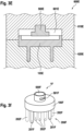
- Figs. 3A to 3F are depictions of various manufacturing steps of making an example head for a personal care device in accordance with the present disclosure and of intermediate head products and of the final head.
- Fig. 3A is a cross-sectional cut through a schematically depicted mold 600A having a first mold half 610A and a second mold half 620A that define a first cavity 601A for injection molding of a front portion of a carrier.
- the separation line between the two mold halves 610A and 620A s indicated to coincide with a plane defining the front surface of the to be injection molded front portion of the carrier - this position of the separation line is understood to be non-limiting.
- two pins 630A and 640A extend into the first cavity 601A, which pins define through-holes in the front portion of the carrier.
- the second mold half 620A may comprise one or several cavity portions 602A for defining a non-embedded portion of a cleaning element. Such a cavity portion would then be sealed by a pin, as is here the case for pin 640A so that no plastic material would flow into cavity portion 602A during the injection of molten plastic material into the first cavity 601A. While in this cross-sectional cut two pins are shown, it should be understood that this is a non-limiting example shown for sake of presenting the concept and in some embodiments only one pin is used, while in other embodiments two or three or four etc. pins are used - just as many as injection molded cleaning elements are planned. This shall also not exclude that further cleaning elements made from, e.g., bundles of fibers are present on the carrier together with at least one of the injection molded cleaning elements.
- Fig. 3B is a cross-sectional cut through a front portion 101B of a carrier made by injecting molten plastic material into the first cavity 601A shown in Fig. 3A .
- the front portion 101B of the carrier has two through-holes 102B and 103B that extend between a front surface 1010B and a back surface 1011B of the front portion 101B of the carrier.
- a channel 104B connecting the two through holes 102B and 103B is shown in the back surface 1011B
- Fig. 3C is a cross-sectional cut through a schematically depicted mold 600C having a first mold half 610C and a second mold half 620C that define a second cavity 601C.
- a front portion 101C is inserted into the cavity 601C as an insert. It shall be understood that the front portion 101C may of course be the front portion 101B shown in Fig. 3B .
- the second cavity 601C with the inserted front portion 101C comprises several cavity portions 6011C to 6017C.
- a central channel cavity portion 6011C is provided on the backside of the front portion 101C of the carrier and two channel arms are defined by cavity portions 6012C and 6013C, which two arms cavity portions 6012C and 6013C connect the central channel cavity portion 6011C with through holes in the front portion 101C of the carrier, which through-holes define cavity portions 6014C and 6015C for molding of embedded portions of cleaning elements.
- the second mold half 620C comprises here two cavity portions 6015C and 6016C that are aligned with the cavity portions 6014C and 6015C, respectively, and that allow to mold non-embedded portions of the cleaning elements.
- a injection nozzle 611C is indicated that is positioned in alignment with the central channel cavity portion 6011C, which is to be understood as a non-limiting example.
- Fig. 3D is a cross-sectional cut through a pre-head 105D comprising a front portion of a carrier 101D and two cleaning elements 200D and 300D that may be the result from an injection molding step into the second cavity shown in Fig. 3C .
- the cleaning elements 200D and 300D are integrally connected by a laterally extending arm 400D on the backside of the front portion 101D.
- the plastic materials of the front portion 101D and of the cleaning elements 200D, 300D may be chosen such that the materials form and chemical and/or physical bond.
- Fig. 3E is a cross-sectional cut through a schematically depicted mold 600E having a first mold half 610E and a second mold half 620E that define a third cavity 601E.
- a pre-head 105E is inserted into the third cavity as is a connector 500E that may serve to connect the final head to be molded with a drive mechanism.
- the pre-head 105E may be the pre-head 105D that is shown in Fig. 3D .
- Molten plastic material that will be injected into the third cavity 601E will connect the pre-head 105D and the connector 500D by a physical and/or chemical bond and/or by a positive fit.
- the material to be injected into the third cavity 601E forms a back portion of the carrier and completely embeds the embedded portion of the cleaning elements 200D and 300D as well as the laterally extending arm 400D.
- Fig. 3F is a depiction of a head 1F that may result from the final injection molding step discussed with respect to Fig. 3E .
- the head 1F comprises a carrier 100F, an array of cleaning elements 200F and a connector 500F.
- the connector 500F may comprise a connecting structure 501F to allow the connection with, e.g., a drive mechanism and/or with a locking mechanism (such as a locking pin) as is commonly known in the art.
- the array of cleaning elements 200F comprises two cleaning elements 201F shown in solid lines. It is here indicated by dashed lines that the head 1F may comprise more than the two cleaning elements that were shown and discussed in the previous Figs. 3A to 3E , namely additional cleaning elements 202F.
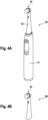
- Fig. 4A is a depiction of a personal care device 10 realized as an electric toothbrush that comprises a handle section 11 and a replaceable attachment 12 at which a head 14 is provided, preferably a head in accordance with the present disclosure.
- Fig. 4B is a depiction of a replaceable attachment 20 realized as a replacement brush head for an electric toothbrush, which replaceable attachment 20 comprises a head 21, preferably a head in accordance with the present disclosure.
Landscapes
- Engineering & Computer Science (AREA)
- Manufacturing & Machinery (AREA)
- Mechanical Engineering (AREA)
- Health & Medical Sciences (AREA)
- Dentistry (AREA)
- Epidemiology (AREA)
- Life Sciences & Earth Sciences (AREA)
- Animal Behavior & Ethology (AREA)
- General Health & Medical Sciences (AREA)
- Public Health (AREA)
- Veterinary Medicine (AREA)
- Chemical & Material Sciences (AREA)
- Materials Engineering (AREA)
- Brushes (AREA)
- Moulds For Moulding Plastics Or The Like (AREA)
- Surgical Instruments (AREA)
- Orthopedics, Nursing, And Contraception (AREA)
- Printers Or Recording Devices Using Electromagnetic And Radiation Means (AREA)
Claims (14)
- Kopf (1) für eine Körperpflegevorrichtung, umfassendeinen Träger (100), der eine vordere Oberfläche (1010) aufweist;wenigstens ein Reinigungselement (200), das ein integrales Reinigungselement ist, das teilweise in den Träger (100) eingebettet ist und somit einen eingebetteten Reinigungselementabschnitt (220) und einen nicht eingebetteten Reinigungselementabschnitt (210) aufweist, wobei sich der nicht eingebettete Reinigungselementabschnitt (210) von der vorderen Oberfläche (1010) des Trägers (100) zwischen einem Basisende (211) auf der vorderen Oberfläche (1010) und einem freien Ende (212) erstreckt und sich der eingebettete Reinigungselementabschnitt (220) von der vorderen Oberfläche (1010) zwischen einem oberen Ende (221) auf der vorderen Oberfläche (1010) und einem unteren Ende (222) erstreckt,wobei das Basisende (211) des nicht eingebetteten Reinigungselementabschnitts (210) eine Basisendquerschnittsform und eine Basisendquerschnittsfläche aufweist und das obere Ende (221) des eingebetteten Reinigungselementabschnitts (220) eine obere Endquerschnittsform, die sich vorzugsweise von der Basisendquerschnittsform unterscheidet, und eine obere Endquerschnittsfläche aufweist, die um wenigstens 20 % größer als die Basisendquerschnittsfläche; undwobei ein integraler Arm (410) das untere Ende (222) des eingebetteten Reinigungselementabschnitts (200) mit einem Mittelpunkt (430) in dem Träger (100) verbindet, wobei der Mittelpunkt (430) seitlich von dem unteren Ende (222) versetzt ist und der integrale Arm (410) vollständig in dem Träger (100) eingebettet ist.
- Kopf nach Anspruch 1, wobei die Querschnittsfläche (225A) des oberen Endes des eingebetteten Reinigungselementabschnitts (220) um wenigstens etwa 30 % größer als die Querschnittsfläche (215A) des unteren Endes des nicht eingebetteten Reinigungselementabschnitts (210) ist.
- Kopf nach Anspruch 1 oder Anspruch 2, wobei das Reinigungselementmaterial ein thermoplastisches Elastomer ist.
- Kopf nach einem der Ansprüche 1 bis 3, wobei ein Material, aus dem der eingebettete Reinigungselementabschnitt (220) hergestellt ist, und ein Material, aus dem der Träger (100) hergestellt ist, chemisch und/oder physikalisch gebunden sind.
- Kopf nach einem der Ansprüche 1 bis 4, wobei sich der eingebettete Reinigungselementabschnitt (220) von dem oberen Ende (221) zu einem Mittelabschnitt (223) oder des unteren Endes (222) erweitert.
- Kopf nach einem der Ansprüche 1 bis 5, wobei der eingebettete Reinigungselementabschnitt (220) eine sich erweiternde Stufe (224) zwischen dem oberen Ende (221) und dem unteren Ende (222) des eingebetteten Reinigungselementabschnitts (220) aufweist.
- Kopf nach einem der Ansprüche 1 bis 6, wobei wenigstens ein weiterer integraler Arm (420) den Mittelpunkt (430) und ein unteres Ende (322) eines eingebetteten Reinigungselementabschnitts (320) eines anderen Reinigungselements (300) verbindet.
- Kopf nach einem der Ansprüche 1 bis 7, wobei eine Haltekraft des Reinigungselements (200) wenigstens 3 Newton beträgt.
- Verfahren zum Herstellen eines Kopfs (1) für ein Körperpflegevorrichtung, vorzugsweise eines Kopfs nach den vorstehenden Ansprüchen, umfassend die Schritte:Bereitstellen eines ersten Hohlraums (601A) in einer Form (600A) zum Definieren eines vorderen Abschnitts (101) eines Trägers (100), die Form (600A) umfassend wenigstens einen Stift (630A; 640A) zum Definieren eines Durchgangslochs (102B) in dem vorderen Abschnitt (101) des Trägers (100), wobei das Durchgangsloch (102B) ein oberes und ein unteres Ende aufweist;Spritzgießen des vorderseitigen Abschnitts (101) des Trägers (100);Bereitstellen eines zweiten Hohlraums (601C) in einer Form (600C), umfassend den vorderseitigen Abschnitt (101) des Trägers (100) als Einsatz, der zweite Hohlraum (601C) umfassend wenigstens einen Hohlraumabschnitt (6015C), der einen nicht eingebetteten Abschnitt (210) eines Reinigungselements (200) definiert, wobei der Hohlraumabschnitt (6015C) eine Erweiterung des Durchgangslochs (102B) in dem vorderseitigen Abschnitt (101) des Trägers (100) ist, wobei der Hohlraumabschnitt (6015C) ein Basisende aufweist, das eine Basisendquerschnittsform und eine Basisendquerschnittsfläche aufweist, und das obere Ende des Durchgangslochs benachbart zu dem Basisende des Hohlraumabschnitts (6015C) ist, das eine obere Endquerschnittsfläche aufweist, die um wenigstens 20 % größer als die Basisendquerschnittsfläche ist, und vorzugsweise eine obere Endquerschnittform aufweist, die sich von der Basisendquerschnittsform unterscheidet;Spritzgießen von wenigstens einem Reinigungselement (200), das den Hohlraumabschnitt (6015C) und das Durchgangsloch (102B) füllt;wobei das Spritzgießen des wenigstens einen Reinigungselements (200) das Spritzgießen von wenigstens dem Reinigungselement (200) und das Füllen eines Hohlraumabschnitts (6012C) der zweiten Form (600C), der einen Kanal für das eingespritzte Material definiert, umfasst, um einen integralen Arm (410) zu schaffen, der ein unteres Ende (222) des Reinigungselements (200) mit einem Mittelpunkt (430) in dem Träger (400) verbindet, wobei der Mittelpunkt (430) von dem unteren Ende (222) seitlich versetzt ist;Bereitstellen eines dritten Hohlraums (601E), umfassend den vorderseitigen Abschnitt (101) des Trägers (100) mit dem spritzgegossenen Reinigungselement (200) als Einsatz und einen Hohlraumabschnitt, der einen rückseitigen Abschnitt (102) des Trägers (100) definiert; undSpritzgießen des rückseitigen Abschnitts (102) des Trägers (100).
- Verfahren nach Anspruch 9, umfassend die weiteren Schritte:Auswählen eines Kunststoffmaterials zum Spritzgießen des vorderseitigen Abschnitts (101) des Trägers (100), vorzugsweise wobei das Kunststoffmaterial ein Thermoplast wie Polypropylen, Polycarbonat oder Polyethylen ist;Auswählen eines Kunststoffmaterials zum Spritzgießen des Reinigungselements (200), wobei das Material vorzugsweise ein thermoplastisches Elastomer ist;wobei die beiden Materialien derart gewählt sind, dass sie eine chemische und/oder physikalische Bindung ausbilden.
- Verfahren nach Anspruch 9 oder Anspruch 10, umfassend den Schritt des Bereitstellens des Stifts (630A) zum Definieren des Durchgangslochs (102A), der eine Form aufweist, derart, dass sich das Durchgangsloch (102A) von dem oberen Ende zu einem Mittelabschnitt oder dem unteren Endes des Durchgangslochs (102A) hin erweitert.
- Verfahren nach Anspruch 9 oder Anspruch 10, umfassend den Schritt des Bereitstellens des Stifts (640A) zum Definieren des Durchgangslochs (103A), das eine Form aufweist, derart, dass das Durchgangsloch eine sich erweiternde Stufe zwischen dem oberen Ende und dem unteren Ende des Durchgangslochs (103A) umfasst.
- Verfahren nach einem der Ansprüche 9 bis 12, wobei das Material zum Spritzgießen des Reinigungselements (200) ein thermoplastisches Elastomer ist, vorzugsweise wobei das thermoplastische Elastomer eine Härte von unter 50 Shore A aufweist.
- Verfahren nach einem der Ansprüche 9 bis 13, wobei das Bereitstellen des ersten Hohlraums (601A) das Bereitstellen von wenigstens einem weiteren Stift (640A) zum Definieren eines weiteren Durchgangslochs (103A) in dem vorderseitigen Abschnitt (101) des Trägers (100) umfasst, und wobei das Spritzgießen des wenigstens einen Reinigungselements (200) das Spritzgießen von wenigstens dem Reinigungselement (200) und einem weiteren Reinigungselement (300) und das Füllen eines Hohlraumabschnitts (6011C, 6012C, 6013C) der zweiten Form (600C), der einen Kanal für das eingespritzte Material definiert, umfasst, um einen integralen Arm (400) zu schaffen, der die unteren Enden (222, 322) der zwei Reinigungselemente (200, 300) verbindet.
Priority Applications (7)
| Application Number | Priority Date | Filing Date | Title |
|---|---|---|---|
| ES21199135T ES3014734T3 (en) | 2021-09-27 | 2021-09-27 | Head for a personal care device and method of making thereof |
| EP21199135.1A EP4154761B1 (de) | 2021-09-27 | 2021-09-27 | Kopf für eine körperpflegevorrichtung und verfahren zu seiner herstellung |
| CA3231681A CA3231681A1 (en) | 2021-09-27 | 2022-09-08 | Head for a personal care device |
| PCT/IB2022/058453 WO2023047231A1 (en) | 2021-09-27 | 2022-09-08 | Head for a personal care device |
| JP2024516540A JP2024533518A (ja) | 2021-09-27 | 2022-09-08 | パーソナルケアデバイス用ヘッド |
| CN202280063558.7A CN118119320A (zh) | 2021-09-27 | 2022-09-08 | 用于个人护理装置的头部 |
| US17/950,646 US12551003B2 (en) | 2021-09-27 | 2022-09-22 | Head for a personal care device |
Applications Claiming Priority (1)
| Application Number | Priority Date | Filing Date | Title |
|---|---|---|---|
| EP21199135.1A EP4154761B1 (de) | 2021-09-27 | 2021-09-27 | Kopf für eine körperpflegevorrichtung und verfahren zu seiner herstellung |
Publications (2)
| Publication Number | Publication Date |
|---|---|
| EP4154761A1 EP4154761A1 (de) | 2023-03-29 |
| EP4154761B1 true EP4154761B1 (de) | 2025-01-15 |
Family
ID=77998726
Family Applications (1)
| Application Number | Title | Priority Date | Filing Date |
|---|---|---|---|
| EP21199135.1A Active EP4154761B1 (de) | 2021-09-27 | 2021-09-27 | Kopf für eine körperpflegevorrichtung und verfahren zu seiner herstellung |
Country Status (7)
| Country | Link |
|---|---|
| US (1) | US12551003B2 (de) |
| EP (1) | EP4154761B1 (de) |
| JP (1) | JP2024533518A (de) |
| CN (1) | CN118119320A (de) |
| CA (1) | CA3231681A1 (de) |
| ES (1) | ES3014734T3 (de) |
| WO (1) | WO2023047231A1 (de) |
Family Cites Families (123)
| Publication number | Priority date | Publication date | Assignee | Title |
|---|---|---|---|---|
| GB601371A (en) * | 1946-05-06 | 1948-05-04 | John Denman Dean | Improvements in or relating to hair and like brushes |
| US1601217A (en) * | 1924-11-17 | 1926-09-28 | Northboro Brush Company | Brush |
| US2273717A (en) * | 1938-01-14 | 1942-02-17 | Lactona Inc | Brush |
| US2363647A (en) * | 1942-09-02 | 1944-11-28 | Hughes Autograf Brush Company | Hairbrush cover |
| US2358464A (en) * | 1942-10-08 | 1944-09-19 | Hughes Autograf Brush Company | Bristle holder for brushes |
| US2409490A (en) * | 1944-05-11 | 1946-10-15 | Toledo Automatic Brush Machine | Tuft anchoring means for brushes |
| US2488873A (en) * | 1945-01-12 | 1949-11-22 | Prophylactic Brush Co | Toothbrush and method of making |
| US2542709A (en) * | 1947-09-27 | 1951-02-20 | Fuller Brush Co | Brush structure with bristles held in channel strip |
| US2482928A (en) * | 1948-03-26 | 1949-09-27 | Neff Augusta | Needle hairbrush |
| DE941364C (de) | 1954-06-03 | 1956-04-12 | Edwin Grether | Verfahren zum Herstellen von Buersten, deren Buerstenkoerper und Borsten aus einem Stueck bestehen, das im Spritzverfahren hergestellt ist, und Buerste nach diesem Verfahren |
| US2923598A (en) | 1954-06-30 | 1960-02-02 | Pittsburgh Plate Glass Co | Method of forming filaments embodying polyurethane resins |
| US2882544A (en) * | 1957-10-23 | 1959-04-21 | Puzant H Hadidian | Tooth brush |
| US3076218A (en) | 1961-06-08 | 1963-02-05 | Johnson & Johnson | Fluorinated toothbrush bristle and method of making same |
| DE2812746C2 (de) | 1978-03-23 | 1985-05-30 | Friedrich Schlesinger, Maschinenfabrik, 3558 Frankenberg | Maschine zur Herstellung von Bürsten |
| JPS62148610A (ja) | 1985-11-19 | 1987-07-02 | 株式会社 新和製作所 | 刷毛用繊維束の製造方法 |
| JP2732875B2 (ja) | 1988-02-03 | 1998-03-30 | コロネツト‐ヴエルケ ハインリツヒ シユレルフ ゲゼルシヤフト ミツト ベシユレンクテル ハフツング | 剛毛製品を製造する方法 |
| US5040260A (en) | 1989-03-16 | 1991-08-20 | Michaels George G | Tooth cleaning and polishing device |
| JPH0631940Y2 (ja) * | 1989-05-10 | 1994-08-24 | ライオン株式会社 | 歯ブラシ |
| DE59007034D1 (de) | 1989-06-24 | 1994-10-13 | Frisetta Gmbh | Verfahren und Vorrichtung zum Herstellen von Borstenfeldern oder Borstenbündeln. |
| US5318352A (en) * | 1990-11-20 | 1994-06-07 | Oraline International B.V. | Method of making a toothbrush |
| JPH0580324U (ja) | 1992-04-01 | 1993-11-02 | 花王株式会社 | 歯ブラシ |
| DE4314692C2 (de) | 1993-05-04 | 1998-11-26 | Zahoransky Anton Gmbh & Co | Verfahren und Vorrichtung zur Herstellung von Bürsten |
| DE4415886A1 (de) * | 1994-05-05 | 1995-11-09 | Coronet Werke Gmbh | Verfahren zur Herstellung von Borstenwaren im Wege des Spritzgießens |
| DE19507364A1 (de) * | 1995-03-03 | 1996-09-05 | Coronet Werke Gmbh | Bürste, insbesondere Hygienebürste |
| JPH0956479A (ja) * | 1995-08-29 | 1997-03-04 | Lion Corp | ブラシおよびその製造方法 |
| US6996870B2 (en) | 1995-12-29 | 2006-02-14 | Colgate-Palmolive Company | Contouring toothbrush head |
| US6036277A (en) * | 1996-02-14 | 2000-03-14 | Coronet-Werke Gmbh | Method for the manufacture of brushware |
| CN2259084Y (zh) | 1996-05-13 | 1997-08-13 | 石汀 | 可调节刷毛硬度的牙刷 |
| TW414035U (en) | 1996-05-14 | 2000-12-01 | Kao Corp | Toothbrush |
| DE19743556A1 (de) | 1997-10-01 | 1999-04-08 | Schiffer Fa M & C | Verfahren und Vorrichtung zur Herstellung einer Zahnbürste |
| DE19745024A1 (de) | 1997-10-11 | 1999-04-15 | Zahoransky Anton Gmbh & Co | Bürstenherstellungsmaschine |
| GB9816914D0 (en) | 1998-08-05 | 1998-09-30 | Smithkline Beecham Gmbh | Novel device |
| US6035476A (en) * | 1998-09-10 | 2000-03-14 | Optiva Corporation | Brushhead for a toothbrush |
| DE19909435A1 (de) | 1999-03-04 | 2000-09-07 | Coronet Werke Gmbh | Verfahren und Vorrichtung zur Herstellung von Borstenwaren und danach hergestellte Borstenwaren |
| GB9907996D0 (en) | 1999-04-09 | 1999-06-02 | Smithkline Beecham Gmbh | Toothbrush |
| JP2001190333A (ja) * | 2000-01-17 | 2001-07-17 | Lion Corp | 歯ブラシおよびその製造方法 |
| DE10015062B4 (de) | 2000-03-25 | 2010-05-12 | Braun Gmbh | Bürstenkopf und Verfahren zur Herstellung eines solchen Bürstenkopfs |
| DE20006311U1 (de) | 2000-04-06 | 2001-08-09 | G.B. Boucherie N.V., Izegem | Vorrichtung zum Befestigen von mit Borstenbüscheln versehenen Plättchen an Bürstenkörpern |
| US6865767B1 (en) | 2000-06-05 | 2005-03-15 | James A. Gavney, Jr. | Device with multi-structural contact elements |
| JP4132744B2 (ja) * | 2000-08-23 | 2008-08-13 | 花王株式会社 | ブラシの製造方法及び装置 |
| US7434288B2 (en) | 2000-09-19 | 2008-10-14 | Gavney Jr James A | Oral care device with multi-structural contact elements |
| US20060230563A1 (en) | 2000-09-19 | 2006-10-19 | Gavney James A Jr | Oral care device with multi-structural contact elements |
| JP3932903B2 (ja) * | 2001-06-14 | 2007-06-20 | 松下電工株式会社 | 電動歯ブラシ |
| JP2003061753A (ja) * | 2001-08-24 | 2003-03-04 | Kao Corp | ブラシの製造方法 |
| JP2003144232A (ja) * | 2001-08-30 | 2003-05-20 | Lion Corp | 歯ブラシハンドルの製造方法 |
| DE10164336A1 (de) | 2001-12-28 | 2003-07-17 | Trisa Holding Ag Triengen | Zahnbürste und Verfahren zur Herstellung einer solchen Zahnbürste |
| DE10212701B4 (de) | 2002-03-21 | 2015-05-13 | Geka Gmbh | Borste, Verfahren und Vorrichtung zu ihrer Herstellung sowie Borstenware |
| DE10217527B4 (de) | 2002-04-19 | 2012-06-21 | Anton Zahoransky Gmbh & Co. | Verfahren zum Herstellen von Bürsten sowie danach hergestellte Bürste |
| US6735803B2 (en) | 2002-06-03 | 2004-05-18 | Youti Kuo | Electrical dentifrice-dispensing toothbrush with replaceable bristle unit and refillable cartridge |
| US7845042B2 (en) * | 2002-08-09 | 2010-12-07 | Colgate-Palmolive Company | Oral care implement |
| EP2510830B1 (de) | 2002-08-09 | 2013-12-25 | Colgate-Palmolive Company | Verfahren zum herstellen einer zahnbürste |
| US7836539B2 (en) * | 2002-08-09 | 2010-11-23 | Colgate-Palmolive Company | Oral care implement |
| US7614111B2 (en) | 2002-08-09 | 2009-11-10 | Colgate-Palmolive Company | Oral care implement |
| US7725980B2 (en) | 2004-12-15 | 2010-06-01 | Colgate-Palmolive Company | Oral care implement |
| BRPI0307110B1 (pt) | 2002-12-03 | 2017-03-28 | Kwon Sung-Wook | escova de dente com cerdas em formato de agulha afuniladas em uma extremidade e método de fabricação da mesma |
| DE10259723A1 (de) | 2002-12-19 | 2004-07-01 | Trisa Holding Ag | Zahnbürste und Verfahren zu deren Herstellung |
| DE102004026461A1 (de) | 2004-05-29 | 2005-12-15 | Braun Gmbh | Bürstenkopf für elektrische und/oder manuelle Zahnbürsten |
| KR100597687B1 (ko) | 2004-09-21 | 2006-07-10 | 주식회사 엘지생활건강 | 칫솔 |
| CA2596685C (en) | 2005-02-02 | 2014-04-01 | Sunstar Inc. | Toothbrush |
| DE102005024082A1 (de) * | 2005-05-25 | 2006-11-30 | M + C Schiffer Gmbh | Bürste und Verfahren zu deren Herstellung |
| DE102006026712A1 (de) | 2006-06-08 | 2007-12-13 | M + C Schiffer Gmbh | Zahnbürste und Verfahren zu deren Herstellung |
| US20090229064A1 (en) * | 2006-11-02 | 2009-09-17 | Robinson Dane Q | Brush and bristle assembly therefor |
| US20080104785A1 (en) * | 2006-11-02 | 2008-05-08 | Robinson Dane Q | Bristle assembly for a brush and related method |
| US8056176B2 (en) * | 2007-01-25 | 2011-11-15 | The Procter & Gamble Company | Toothbrushes |
| US8032971B2 (en) | 2007-02-23 | 2011-10-11 | Colgate-Palmolive Company | Oral care implement having tooth whitening elements |
| DE102007018766A1 (de) | 2007-04-20 | 2008-10-23 | Braun Gmbh | Zahnbürste |
| US20090007357A1 (en) | 2007-05-07 | 2009-01-08 | The Gillette Company | Oral Hygiene Implements |
| DE102008039778A1 (de) | 2008-08-26 | 2010-03-04 | Firma G.B. Boucherie N.V. | Verfahren zur Herstellung von Bürsten, insbesondere Zahnbürsten |
| US8434190B2 (en) * | 2008-09-01 | 2013-05-07 | Braun Gmbh | Toothbrush and method of manufacturing it |
| US9655435B2 (en) | 2008-12-15 | 2017-05-23 | Glaxosmithkline Consumer Healthcare Gmbh & Co., Kg | Toothbrush bristle arrangement |
| EP2243394A1 (de) | 2009-04-21 | 2010-10-27 | M+C Schiffer GmbH | Verfahren zur Bildung eines Borstenbündels sowie eine zur Durchführung des Verfahrens geeignete Vorrichtung |
| DE102009039514A1 (de) | 2009-08-31 | 2011-03-03 | Gb Boucherie Nv | Verfahren zur Herstellung von Bürsten, insbesondere Zahnbürsten |
| US20110099739A1 (en) * | 2009-11-05 | 2011-05-05 | Edward Whillock | Interchangeable tooth brush and associated method for promoting oral health |
| ES2972464T3 (es) | 2009-11-13 | 2024-06-12 | Sunstar Inc | Filamento de composite de núcleo/vaina para cepillos de dientes, y cepillo de dientes que lo utiliza |
| BR112012014065B1 (pt) | 2009-12-10 | 2020-03-10 | Braun Gmbh | Escova de dentes |
| JP2012000150A (ja) * | 2010-06-14 | 2012-01-05 | Panasonic Electric Works Co Ltd | ブラシ体およびこれを備える歯ブラシ |
| JP2012000148A (ja) | 2010-06-14 | 2012-01-05 | Panasonic Electric Works Co Ltd | ブラシ体およびこれを備えた歯ブラシ |
| EP2420157B1 (de) | 2010-08-18 | 2016-03-30 | Trisa Holding AG | Zahnbürste mit Borstenfeldgestaltung |
| WO2012083488A1 (en) | 2010-12-21 | 2012-06-28 | Cogate-Palmolive Company | Oral care implement |
| EP2661191B1 (de) * | 2011-01-04 | 2019-06-12 | Trisa Holding AG | Zahnbürste mit gespritzten borsten |
| JP3172569U (ja) | 2011-03-03 | 2012-01-05 | リジェンティス株式会社 | 熔着歯ブラシとその製造方法。 |
| JP5224618B2 (ja) | 2011-04-01 | 2013-07-03 | 花王株式会社 | ブラシの製造方法及び装置 |
| EP2720575B1 (de) | 2011-06-15 | 2018-11-28 | The Gillette Company LLC | Vorrichtung für die mündliche pflege deren kopf mit zwei biegsamen flügeln vorgesehen ist |
| EP2534973B1 (de) | 2011-06-15 | 2015-04-08 | Braun GmbH | Verfahren und Werkzeug zur Herstellung eines Bürstenkopfs |
| CN103957747B (zh) | 2011-12-02 | 2016-02-24 | 博朗有限公司 | 制备用于口腔护理装置的刷头区段的方法和装置以及由所述方法和/或所述装置制备的刷头区段 |
| AU2012372822B2 (en) | 2012-03-09 | 2015-02-19 | Colgate-Palmolive Company | Method of forming a head plate and formation of oral care implement using the same |
| DE102012005311B4 (de) | 2012-03-19 | 2021-08-12 | Zahoransky Ag | Vorrichtung zum Herstellen von Bürsten oder Borstenwaren, sowie Bürste oder Borstenware |
| EP2674061B1 (de) | 2012-06-12 | 2017-07-19 | Braun GmbH | Verfahren und Werkzeug zur Herstellung eines Bürstenkopfs |
| WO2014054911A2 (ko) | 2012-10-04 | 2014-04-10 | 비비씨 주식회사 | 칫솔모 제조방법 및 이를 이용한 칫솔 |
| DE102012021311A1 (de) | 2012-10-31 | 2014-04-30 | Zahoransky Formenbau Gmbh | Vorrichtung und Verfahren zur Herstellung von Bürstenkörpern oder Teil-Bürstenkörpern |
| WO2014070542A1 (en) | 2012-11-05 | 2014-05-08 | The Gillette Company | Toothbrush comprising elastomeric cleaning elements over-molded with a harder plastic and method for producing the same |
| US9717324B2 (en) | 2013-05-29 | 2017-08-01 | The Gillette Company Llc | Method for producing a toothbrush and toothbrush produced thereby |
| ES2682256T5 (en) | 2013-06-06 | 2025-11-06 | Procter & Gamble | Head for an oral care implement |
| US20140359957A1 (en) | 2013-06-06 | 2014-12-11 | The Gillette Company | Head for an oral care implement |
| EP2810581B1 (de) | 2013-06-06 | 2018-04-18 | The Gillette Company LLC | Kopf für ein Mundpflegehilfsmittel |
| US20150097309A1 (en) | 2013-10-04 | 2015-04-09 | The Procter & Gamble Company | Process and apparatus for making tufted article |
| CN105813504B (zh) | 2013-12-12 | 2018-05-08 | 高露洁-棕榄公司 | 具有带有不同的口腔护理添加剂的部件的多部件式刷毛以及包括该多部件式刷毛的口腔护理器具 |
| EP2886009B1 (de) | 2013-12-18 | 2019-01-30 | The Gillette Company LLC | Vorrichtung zum verschmelzen der enden von thermoplastischen fäden und entsprechendes verfahren |
| ES2774301T3 (es) | 2014-02-21 | 2020-07-20 | Procter & Gamble | Cabezal para un utensilio de cuidado bucal |
| KR20170017891A (ko) | 2014-05-29 | 2017-02-15 | 콜게이트-파아므올리브캄파니 | 구강 관리 도구 |
| EP2959797A1 (de) | 2014-06-27 | 2015-12-30 | Trisa Holding AG | Zahnbürste mit bewegten Elementen |
| JP6423630B2 (ja) * | 2014-06-30 | 2018-11-14 | 花王株式会社 | 毛穴洗浄用ブラシ |
| EP3485763B1 (de) | 2014-07-23 | 2020-09-09 | Colgate-Palmolive Company | Mundpflegevorrichtung |
| US11291293B2 (en) | 2014-12-23 | 2022-04-05 | Colgate-Palmolive Company | Oral care implement |
| JP6544003B2 (ja) * | 2015-03-31 | 2019-07-17 | サンスター株式会社 | 歯ブラシ |
| CN107624043B (zh) | 2015-05-14 | 2020-07-10 | 皇家飞利浦有限公司 | 刷头组件及制造方法 |
| EP3294088B1 (de) | 2015-05-14 | 2022-07-06 | Koninklijke Philips N.V. | Bürstenkopfanordnung und verfahren zur herstellung |
| EP3138437B1 (de) * | 2015-09-03 | 2021-11-10 | Braun GmbH | Verfahren zum herstellen einer bürste |
| ES2909964T3 (es) | 2015-11-09 | 2022-05-11 | Mc Schiffer Gmbh | Cabezal de cepillo para un cepillo de dientes de accionamiento eléctrico |
| US10136723B2 (en) * | 2015-12-14 | 2018-11-27 | Colgate-Palmolive Company | Oral care implement |
| EP3262974B1 (de) | 2016-06-27 | 2024-06-12 | The Procter & Gamble Company | Verfahren zur herstellung von zahnbürstenköpfen mit einem zweikomponentenreinigungselement |
| EP3262975B1 (de) | 2016-06-28 | 2019-02-20 | The Procter and Gamble Company | Verfahren zur herstellung einer bürste |
| MX2019003205A (es) * | 2016-09-26 | 2019-07-04 | Colgate Palmolive Co | Implemento para el cuidado bucal o placa del cabezal para este y metodo para formarlo. |
| WO2019011599A1 (en) | 2017-07-12 | 2019-01-17 | Koninklijke Philips N.V. | METHOD FOR MANUFACTURING BRUSH HEAD |
| CN109497689B (zh) * | 2017-09-15 | 2021-03-12 | 高露洁-棕榄公司 | 口腔护理器具 |
| US10548392B2 (en) * | 2017-11-18 | 2020-02-04 | Tifinity Oral Care, Llc | Toothbrush with bristle-mounting system for retarding bristle strain |
| RU2020123469A (ru) * | 2018-03-29 | 2022-04-29 | Санси Ко., Лтд. | Зубная щетка |
| CA3043205A1 (en) * | 2018-05-21 | 2019-11-21 | Sunstar Americas, Inc. | Toothbrush bristle and bristle tuft |
| EP3753446B1 (de) | 2019-06-21 | 2025-10-22 | The Procter & Gamble Company | Reinigungselementträger und zahnbürstenkopf damit |
| EP3753447B1 (de) | 2019-06-21 | 2025-12-10 | The Procter & Gamble Company | Verfahren zur herstellung eines zahnbürstenkopfes oder eines teils davon |
| EP3753449A1 (de) | 2019-06-21 | 2020-12-23 | The Procter & Gamble Company | Lochperforationsplatte zur herstellung eines zahnbürstenkopfes und teil davon |
| EP3753445B1 (de) | 2019-06-21 | 2025-12-10 | The Procter & Gamble Company | Zahnbürstenkopf und teil davon |
| EP3753448B1 (de) | 2019-06-21 | 2025-12-10 | The Procter & Gamble Company | Verfahren zur herstellung eines zahnbürstenkopfs |
-
2021
- 2021-09-27 EP EP21199135.1A patent/EP4154761B1/de active Active
- 2021-09-27 ES ES21199135T patent/ES3014734T3/es active Active
-
2022
- 2022-09-08 CA CA3231681A patent/CA3231681A1/en active Pending
- 2022-09-08 JP JP2024516540A patent/JP2024533518A/ja active Pending
- 2022-09-08 CN CN202280063558.7A patent/CN118119320A/zh active Pending
- 2022-09-08 WO PCT/IB2022/058453 patent/WO2023047231A1/en not_active Ceased
- 2022-09-22 US US17/950,646 patent/US12551003B2/en active Active
Also Published As
| Publication number | Publication date |
|---|---|
| CN118119320A (zh) | 2024-05-31 |
| EP4154761A1 (de) | 2023-03-29 |
| US12551003B2 (en) | 2026-02-17 |
| US20230097486A1 (en) | 2023-03-30 |
| CA3231681A1 (en) | 2023-03-30 |
| WO2023047231A1 (en) | 2023-03-30 |
| JP2024533518A (ja) | 2024-09-12 |
| ES3014734T3 (en) | 2025-04-24 |
Similar Documents
| Publication | Publication Date | Title |
|---|---|---|
| EP2477521B1 (de) | Mundpflegeprodukte | |
| AU2008211597B2 (en) | Oral hygiene implements having flexible elements, and methods of making the same | |
| US20210093427A1 (en) | Flosser | |
| KR101169503B1 (ko) | 칫솔 | |
| CN102395295B (zh) | 牙刷及其制造方法 | |
| AU2018244768B2 (en) | Head for an oral care implement, oral care implement and method for manufacturing such head | |
| EP2934228B2 (de) | Mundpflegevorrichtung | |
| CN103260461B (zh) | 口腔护理器具 | |
| EP3262974B1 (de) | Verfahren zur herstellung von zahnbürstenköpfen mit einem zweikomponentenreinigungselement | |
| CZ298597A3 (cs) | Zubní kartáček | |
| CN111885944B (zh) | 口腔护理器具及其形成方法 | |
| JP4581716B2 (ja) | 歯間清掃具およびその製造方法 | |
| KR20050067219A (ko) | 칫솔 | |
| EP2335644B1 (de) | Orales Reinigungselement | |
| EP4154761A1 (de) | Kopf für eine körperpflegevorrichtung | |
| EP2496113B1 (de) | Zahnbürste | |
| JP2022000183A (ja) | 口腔ケア器具用の毛束及びヘッド並びに口腔ケア器具 | |
| KR101697244B1 (ko) | 칫솔 | |
| JP2008178629A (ja) | 腰砕けを防止した樹脂捩じりブラシ | |
| HUP9902896A2 (hu) | Fogkefe elasztomerrel töltött hajlékony fejjel |
Legal Events
| Date | Code | Title | Description |
|---|---|---|---|
| PUAI | Public reference made under article 153(3) epc to a published international application that has entered the european phase |
Free format text: ORIGINAL CODE: 0009012 |
|
| STAA | Information on the status of an ep patent application or granted ep patent |
Free format text: STATUS: THE APPLICATION HAS BEEN PUBLISHED |
|
| AK | Designated contracting states |
Kind code of ref document: A1 Designated state(s): AL AT BE BG CH CY CZ DE DK EE ES FI FR GB GR HR HU IE IS IT LI LT LU LV MC MK MT NL NO PL PT RO RS SE SI SK SM TR |
|
| P01 | Opt-out of the competence of the unified patent court (upc) registered |
Effective date: 20230430 |
|
| STAA | Information on the status of an ep patent application or granted ep patent |
Free format text: STATUS: REQUEST FOR EXAMINATION WAS MADE |
|
| 17P | Request for examination filed |
Effective date: 20230926 |
|
| RBV | Designated contracting states (corrected) |
Designated state(s): AL AT BE BG CH CY CZ DE DK EE ES FI FR GB GR HR HU IE IS IT LI LT LU LV MC MK MT NL NO PL PT RO RS SE SI SK SM TR |
|
| STAA | Information on the status of an ep patent application or granted ep patent |
Free format text: STATUS: EXAMINATION IS IN PROGRESS |
|
| 17Q | First examination report despatched |
Effective date: 20240229 |
|
| GRAP | Despatch of communication of intention to grant a patent |
Free format text: ORIGINAL CODE: EPIDOSNIGR1 |
|
| STAA | Information on the status of an ep patent application or granted ep patent |
Free format text: STATUS: GRANT OF PATENT IS INTENDED |
|
| INTG | Intention to grant announced |
Effective date: 20240925 |
|
| GRAS | Grant fee paid |
Free format text: ORIGINAL CODE: EPIDOSNIGR3 |
|
| GRAA | (expected) grant |
Free format text: ORIGINAL CODE: 0009210 |
|
| STAA | Information on the status of an ep patent application or granted ep patent |
Free format text: STATUS: THE PATENT HAS BEEN GRANTED |
|
| AK | Designated contracting states |
Kind code of ref document: B1 Designated state(s): AL AT BE BG CH CY CZ DE DK EE ES FI FR GB GR HR HU IE IS IT LI LT LU LV MC MK MT NL NO PL PT RO RS SE SI SK SM TR |
|
| REG | Reference to a national code |
Ref country code: CH Ref legal event code: EP Ref country code: GB Ref legal event code: FG4D |
|
| REG | Reference to a national code |
Ref country code: DE Ref legal event code: R096 Ref document number: 602021024900 Country of ref document: DE |
|
| REG | Reference to a national code |
Ref country code: IE Ref legal event code: FG4D |
|
| REG | Reference to a national code |
Ref country code: NL Ref legal event code: FP |
|
| REG | Reference to a national code |
Ref country code: ES Ref legal event code: FG2A Ref document number: 3014734 Country of ref document: ES Kind code of ref document: T3 Effective date: 20250424 |
|
| PG25 | Lapsed in a contracting state [announced via postgrant information from national office to epo] |
Ref country code: RS Free format text: LAPSE BECAUSE OF FAILURE TO SUBMIT A TRANSLATION OF THE DESCRIPTION OR TO PAY THE FEE WITHIN THE PRESCRIBED TIME-LIMIT Effective date: 20250415 |
|
| PG25 | Lapsed in a contracting state [announced via postgrant information from national office to epo] |
Ref country code: FI Free format text: LAPSE BECAUSE OF FAILURE TO SUBMIT A TRANSLATION OF THE DESCRIPTION OR TO PAY THE FEE WITHIN THE PRESCRIBED TIME-LIMIT Effective date: 20250115 |
|
| PG25 | Lapsed in a contracting state [announced via postgrant information from national office to epo] |
Ref country code: PL Free format text: LAPSE BECAUSE OF FAILURE TO SUBMIT A TRANSLATION OF THE DESCRIPTION OR TO PAY THE FEE WITHIN THE PRESCRIBED TIME-LIMIT Effective date: 20250115 |
|
| REG | Reference to a national code |
Ref country code: LT Ref legal event code: MG9D |
|
| PG25 | Lapsed in a contracting state [announced via postgrant information from national office to epo] |
Ref country code: IS Free format text: LAPSE BECAUSE OF FAILURE TO SUBMIT A TRANSLATION OF THE DESCRIPTION OR TO PAY THE FEE WITHIN THE PRESCRIBED TIME-LIMIT Effective date: 20250515 Ref country code: NO Free format text: LAPSE BECAUSE OF FAILURE TO SUBMIT A TRANSLATION OF THE DESCRIPTION OR TO PAY THE FEE WITHIN THE PRESCRIBED TIME-LIMIT Effective date: 20250415 |
|
| REG | Reference to a national code |
Ref country code: AT Ref legal event code: MK05 Ref document number: 1759247 Country of ref document: AT Kind code of ref document: T Effective date: 20250115 |
|
| PG25 | Lapsed in a contracting state [announced via postgrant information from national office to epo] |
Ref country code: HR Free format text: LAPSE BECAUSE OF FAILURE TO SUBMIT A TRANSLATION OF THE DESCRIPTION OR TO PAY THE FEE WITHIN THE PRESCRIBED TIME-LIMIT Effective date: 20250115 |
|
| PG25 | Lapsed in a contracting state [announced via postgrant information from national office to epo] |
Ref country code: PT Free format text: LAPSE BECAUSE OF FAILURE TO SUBMIT A TRANSLATION OF THE DESCRIPTION OR TO PAY THE FEE WITHIN THE PRESCRIBED TIME-LIMIT Effective date: 20250515 Ref country code: LV Free format text: LAPSE BECAUSE OF FAILURE TO SUBMIT A TRANSLATION OF THE DESCRIPTION OR TO PAY THE FEE WITHIN THE PRESCRIBED TIME-LIMIT Effective date: 20250115 |
|
| PG25 | Lapsed in a contracting state [announced via postgrant information from national office to epo] |
Ref country code: BG Free format text: LAPSE BECAUSE OF FAILURE TO SUBMIT A TRANSLATION OF THE DESCRIPTION OR TO PAY THE FEE WITHIN THE PRESCRIBED TIME-LIMIT Effective date: 20250115 Ref country code: GR Free format text: LAPSE BECAUSE OF FAILURE TO SUBMIT A TRANSLATION OF THE DESCRIPTION OR TO PAY THE FEE WITHIN THE PRESCRIBED TIME-LIMIT Effective date: 20250416 |
|
| PG25 | Lapsed in a contracting state [announced via postgrant information from national office to epo] |
Ref country code: AT Free format text: LAPSE BECAUSE OF FAILURE TO SUBMIT A TRANSLATION OF THE DESCRIPTION OR TO PAY THE FEE WITHIN THE PRESCRIBED TIME-LIMIT Effective date: 20250115 |
|
| PG25 | Lapsed in a contracting state [announced via postgrant information from national office to epo] |
Ref country code: SE Free format text: LAPSE BECAUSE OF FAILURE TO SUBMIT A TRANSLATION OF THE DESCRIPTION OR TO PAY THE FEE WITHIN THE PRESCRIBED TIME-LIMIT Effective date: 20250115 |
|
| PGFP | Annual fee paid to national office [announced via postgrant information from national office to epo] |
Ref country code: NL Payment date: 20250814 Year of fee payment: 5 |
|
| REG | Reference to a national code |
Ref country code: CH Ref legal event code: U11 Free format text: ST27 STATUS EVENT CODE: U-0-0-U10-U11 (AS PROVIDED BY THE NATIONAL OFFICE) Effective date: 20251001 |
|
| PG25 | Lapsed in a contracting state [announced via postgrant information from national office to epo] |
Ref country code: SM Free format text: LAPSE BECAUSE OF FAILURE TO SUBMIT A TRANSLATION OF THE DESCRIPTION OR TO PAY THE FEE WITHIN THE PRESCRIBED TIME-LIMIT Effective date: 20250115 |
|
| PG25 | Lapsed in a contracting state [announced via postgrant information from national office to epo] |
Ref country code: DK Free format text: LAPSE BECAUSE OF FAILURE TO SUBMIT A TRANSLATION OF THE DESCRIPTION OR TO PAY THE FEE WITHIN THE PRESCRIBED TIME-LIMIT Effective date: 20250115 |
|
| PGFP | Annual fee paid to national office [announced via postgrant information from national office to epo] |
Ref country code: DE Payment date: 20250805 Year of fee payment: 5 |
|
| PG25 | Lapsed in a contracting state [announced via postgrant information from national office to epo] |
Ref country code: IT Free format text: LAPSE BECAUSE OF FAILURE TO SUBMIT A TRANSLATION OF THE DESCRIPTION OR TO PAY THE FEE WITHIN THE PRESCRIBED TIME-LIMIT Effective date: 20250115 |
|
| PGFP | Annual fee paid to national office [announced via postgrant information from national office to epo] |
Ref country code: GB Payment date: 20250807 Year of fee payment: 5 |
|
| REG | Reference to a national code |
Ref country code: DE Ref legal event code: R097 Ref document number: 602021024900 Country of ref document: DE |
|
| PGFP | Annual fee paid to national office [announced via postgrant information from national office to epo] |
Ref country code: FR Payment date: 20250808 Year of fee payment: 5 |
|
| PG25 | Lapsed in a contracting state [announced via postgrant information from national office to epo] |
Ref country code: CZ Free format text: LAPSE BECAUSE OF FAILURE TO SUBMIT A TRANSLATION OF THE DESCRIPTION OR TO PAY THE FEE WITHIN THE PRESCRIBED TIME-LIMIT Effective date: 20250115 Ref country code: EE Free format text: LAPSE BECAUSE OF FAILURE TO SUBMIT A TRANSLATION OF THE DESCRIPTION OR TO PAY THE FEE WITHIN THE PRESCRIBED TIME-LIMIT Effective date: 20250115 |
|
| PG25 | Lapsed in a contracting state [announced via postgrant information from national office to epo] |
Ref country code: RO Free format text: LAPSE BECAUSE OF FAILURE TO SUBMIT A TRANSLATION OF THE DESCRIPTION OR TO PAY THE FEE WITHIN THE PRESCRIBED TIME-LIMIT Effective date: 20250115 |
|
| PG25 | Lapsed in a contracting state [announced via postgrant information from national office to epo] |
Ref country code: SK Free format text: LAPSE BECAUSE OF FAILURE TO SUBMIT A TRANSLATION OF THE DESCRIPTION OR TO PAY THE FEE WITHIN THE PRESCRIBED TIME-LIMIT Effective date: 20250115 |
|
| PLBE | No opposition filed within time limit |
Free format text: ORIGINAL CODE: 0009261 |
|
| STAA | Information on the status of an ep patent application or granted ep patent |
Free format text: STATUS: NO OPPOSITION FILED WITHIN TIME LIMIT |
|
| 26N | No opposition filed |
Effective date: 20251016 |
|
| PGFP | Annual fee paid to national office [announced via postgrant information from national office to epo] |
Ref country code: CH Payment date: 20251001 Year of fee payment: 5 |
|
| PGFP | Annual fee paid to national office [announced via postgrant information from national office to epo] |
Ref country code: ES Payment date: 20251017 Year of fee payment: 5 |