EP4154833B1 - Gewebeschneider und minimalinvasives chirurgisches instrument - Google Patents
Gewebeschneider und minimalinvasives chirurgisches instrument Download PDFInfo
- Publication number
- EP4154833B1 EP4154833B1 EP21826021.4A EP21826021A EP4154833B1 EP 4154833 B1 EP4154833 B1 EP 4154833B1 EP 21826021 A EP21826021 A EP 21826021A EP 4154833 B1 EP4154833 B1 EP 4154833B1
- Authority
- EP
- European Patent Office
- Prior art keywords
- tissue cutting
- tissue
- reefing
- cutting stent
- thread
- Prior art date
- Legal status (The legal status is an assumption and is not a legal conclusion. Google has not performed a legal analysis and makes no representation as to the accuracy of the status listed.)
- Active
Links
Images



Classifications
-
- A—HUMAN NECESSITIES
- A61—MEDICAL OR VETERINARY SCIENCE; HYGIENE
- A61B—DIAGNOSIS; SURGERY; IDENTIFICATION
- A61B18/00—Surgical instruments, devices or methods for transferring non-mechanical forms of energy to or from the body
- A61B18/04—Surgical instruments, devices or methods for transferring non-mechanical forms of energy to or from the body by heating
- A61B18/12—Surgical instruments, devices or methods for transferring non-mechanical forms of energy to or from the body by heating by passing a current through the tissue to be heated, e.g. high-frequency current
-
- A—HUMAN NECESSITIES
- A61—MEDICAL OR VETERINARY SCIENCE; HYGIENE
- A61B—DIAGNOSIS; SURGERY; IDENTIFICATION
- A61B17/00—Surgical instruments, devices or methods
- A61B17/32—Surgical cutting instruments
- A61B17/3205—Excision instruments
- A61B17/32056—Surgical snare instruments
-
- A—HUMAN NECESSITIES
- A61—MEDICAL OR VETERINARY SCIENCE; HYGIENE
- A61B—DIAGNOSIS; SURGERY; IDENTIFICATION
- A61B18/00—Surgical instruments, devices or methods for transferring non-mechanical forms of energy to or from the body
- A61B18/04—Surgical instruments, devices or methods for transferring non-mechanical forms of energy to or from the body by heating
- A61B18/12—Surgical instruments, devices or methods for transferring non-mechanical forms of energy to or from the body by heating by passing a current through the tissue to be heated, e.g. high-frequency current
- A61B18/14—Probes or electrodes therefor
- A61B18/1477—Needle-like probes
-
- A—HUMAN NECESSITIES
- A61—MEDICAL OR VETERINARY SCIENCE; HYGIENE
- A61B—DIAGNOSIS; SURGERY; IDENTIFICATION
- A61B17/00—Surgical instruments, devices or methods
- A61B17/00234—Surgical instruments, devices or methods for minimally invasive surgery
-
- A—HUMAN NECESSITIES
- A61—MEDICAL OR VETERINARY SCIENCE; HYGIENE
- A61B—DIAGNOSIS; SURGERY; IDENTIFICATION
- A61B17/00—Surgical instruments, devices or methods
- A61B17/34—Trocars; Puncturing needles
-
- A—HUMAN NECESSITIES
- A61—MEDICAL OR VETERINARY SCIENCE; HYGIENE
- A61B—DIAGNOSIS; SURGERY; IDENTIFICATION
- A61B18/00—Surgical instruments, devices or methods for transferring non-mechanical forms of energy to or from the body
- A61B18/04—Surgical instruments, devices or methods for transferring non-mechanical forms of energy to or from the body by heating
- A61B18/12—Surgical instruments, devices or methods for transferring non-mechanical forms of energy to or from the body by heating by passing a current through the tissue to be heated, e.g. high-frequency current
- A61B18/14—Probes or electrodes therefor
- A61B18/1482—Probes or electrodes therefor having a long rigid shaft for accessing the inner body transcutaneously in minimal invasive surgery, e.g. laparoscopy
-
- A—HUMAN NECESSITIES
- A61—MEDICAL OR VETERINARY SCIENCE; HYGIENE
- A61B—DIAGNOSIS; SURGERY; IDENTIFICATION
- A61B18/00—Surgical instruments, devices or methods for transferring non-mechanical forms of energy to or from the body
- A61B18/04—Surgical instruments, devices or methods for transferring non-mechanical forms of energy to or from the body by heating
- A61B18/12—Surgical instruments, devices or methods for transferring non-mechanical forms of energy to or from the body by heating by passing a current through the tissue to be heated, e.g. high-frequency current
- A61B18/14—Probes or electrodes therefor
- A61B18/1487—Trocar-like, i.e. devices producing an enlarged transcutaneous opening
-
- A—HUMAN NECESSITIES
- A61—MEDICAL OR VETERINARY SCIENCE; HYGIENE
- A61B—DIAGNOSIS; SURGERY; IDENTIFICATION
- A61B17/00—Surgical instruments, devices or methods
- A61B17/00234—Surgical instruments, devices or methods for minimally invasive surgery
- A61B2017/00287—Bags for minimally invasive surgery
-
- A—HUMAN NECESSITIES
- A61—MEDICAL OR VETERINARY SCIENCE; HYGIENE
- A61B—DIAGNOSIS; SURGERY; IDENTIFICATION
- A61B18/00—Surgical instruments, devices or methods for transferring non-mechanical forms of energy to or from the body
- A61B2018/00053—Mechanical features of the instrument of device
- A61B2018/00214—Expandable means emitting energy, e.g. by elements carried thereon
- A61B2018/00267—Expandable means emitting energy, e.g. by elements carried thereon having a basket shaped structure
-
- A—HUMAN NECESSITIES
- A61—MEDICAL OR VETERINARY SCIENCE; HYGIENE
- A61B—DIAGNOSIS; SURGERY; IDENTIFICATION
- A61B18/00—Surgical instruments, devices or methods for transferring non-mechanical forms of energy to or from the body
- A61B2018/00571—Surgical instruments, devices or methods for transferring non-mechanical forms of energy to or from the body for achieving a particular surgical effect
- A61B2018/00577—Ablation
-
- A—HUMAN NECESSITIES
- A61—MEDICAL OR VETERINARY SCIENCE; HYGIENE
- A61B—DIAGNOSIS; SURGERY; IDENTIFICATION
- A61B18/00—Surgical instruments, devices or methods for transferring non-mechanical forms of energy to or from the body
- A61B2018/00571—Surgical instruments, devices or methods for transferring non-mechanical forms of energy to or from the body for achieving a particular surgical effect
- A61B2018/00589—Coagulation
-
- A—HUMAN NECESSITIES
- A61—MEDICAL OR VETERINARY SCIENCE; HYGIENE
- A61B—DIAGNOSIS; SURGERY; IDENTIFICATION
- A61B18/00—Surgical instruments, devices or methods for transferring non-mechanical forms of energy to or from the body
- A61B2018/00571—Surgical instruments, devices or methods for transferring non-mechanical forms of energy to or from the body for achieving a particular surgical effect
- A61B2018/00601—Cutting
-
- A—HUMAN NECESSITIES
- A61—MEDICAL OR VETERINARY SCIENCE; HYGIENE
- A61B—DIAGNOSIS; SURGERY; IDENTIFICATION
- A61B18/00—Surgical instruments, devices or methods for transferring non-mechanical forms of energy to or from the body
- A61B2018/00571—Surgical instruments, devices or methods for transferring non-mechanical forms of energy to or from the body for achieving a particular surgical effect
- A61B2018/00607—Coagulation and cutting with the same instrument
-
- A—HUMAN NECESSITIES
- A61—MEDICAL OR VETERINARY SCIENCE; HYGIENE
- A61B—DIAGNOSIS; SURGERY; IDENTIFICATION
- A61B18/00—Surgical instruments, devices or methods for transferring non-mechanical forms of energy to or from the body
- A61B18/04—Surgical instruments, devices or methods for transferring non-mechanical forms of energy to or from the body by heating
- A61B18/12—Surgical instruments, devices or methods for transferring non-mechanical forms of energy to or from the body by heating by passing a current through the tissue to be heated, e.g. high-frequency current
- A61B18/14—Probes or electrodes therefor
- A61B2018/1405—Electrodes having a specific shape
-
- A—HUMAN NECESSITIES
- A61—MEDICAL OR VETERINARY SCIENCE; HYGIENE
- A61B—DIAGNOSIS; SURGERY; IDENTIFICATION
- A61B18/00—Surgical instruments, devices or methods for transferring non-mechanical forms of energy to or from the body
- A61B18/04—Surgical instruments, devices or methods for transferring non-mechanical forms of energy to or from the body by heating
- A61B18/12—Surgical instruments, devices or methods for transferring non-mechanical forms of energy to or from the body by heating by passing a current through the tissue to be heated, e.g. high-frequency current
- A61B18/14—Probes or electrodes therefor
- A61B2018/1405—Electrodes having a specific shape
- A61B2018/1407—Loop
-
- A—HUMAN NECESSITIES
- A61—MEDICAL OR VETERINARY SCIENCE; HYGIENE
- A61B—DIAGNOSIS; SURGERY; IDENTIFICATION
- A61B18/00—Surgical instruments, devices or methods for transferring non-mechanical forms of energy to or from the body
- A61B18/04—Surgical instruments, devices or methods for transferring non-mechanical forms of energy to or from the body by heating
- A61B18/12—Surgical instruments, devices or methods for transferring non-mechanical forms of energy to or from the body by heating by passing a current through the tissue to be heated, e.g. high-frequency current
- A61B18/14—Probes or electrodes therefor
- A61B2018/1405—Electrodes having a specific shape
- A61B2018/1407—Loop
- A61B2018/141—Snare
-
- A—HUMAN NECESSITIES
- A61—MEDICAL OR VETERINARY SCIENCE; HYGIENE
- A61B—DIAGNOSIS; SURGERY; IDENTIFICATION
- A61B18/00—Surgical instruments, devices or methods for transferring non-mechanical forms of energy to or from the body
- A61B18/04—Surgical instruments, devices or methods for transferring non-mechanical forms of energy to or from the body by heating
- A61B18/12—Surgical instruments, devices or methods for transferring non-mechanical forms of energy to or from the body by heating by passing a current through the tissue to be heated, e.g. high-frequency current
- A61B18/14—Probes or electrodes therefor
- A61B2018/1405—Electrodes having a specific shape
- A61B2018/1425—Needle
-
- A—HUMAN NECESSITIES
- A61—MEDICAL OR VETERINARY SCIENCE; HYGIENE
- A61B—DIAGNOSIS; SURGERY; IDENTIFICATION
- A61B18/00—Surgical instruments, devices or methods for transferring non-mechanical forms of energy to or from the body
- A61B18/04—Surgical instruments, devices or methods for transferring non-mechanical forms of energy to or from the body by heating
- A61B18/12—Surgical instruments, devices or methods for transferring non-mechanical forms of energy to or from the body by heating by passing a current through the tissue to be heated, e.g. high-frequency current
- A61B18/14—Probes or electrodes therefor
- A61B2018/1405—Electrodes having a specific shape
- A61B2018/144—Wire
-
- A—HUMAN NECESSITIES
- A61—MEDICAL OR VETERINARY SCIENCE; HYGIENE
- A61B—DIAGNOSIS; SURGERY; IDENTIFICATION
- A61B18/00—Surgical instruments, devices or methods for transferring non-mechanical forms of energy to or from the body
- A61B18/04—Surgical instruments, devices or methods for transferring non-mechanical forms of energy to or from the body by heating
- A61B18/12—Surgical instruments, devices or methods for transferring non-mechanical forms of energy to or from the body by heating by passing a current through the tissue to be heated, e.g. high-frequency current
- A61B18/14—Probes or electrodes therefor
- A61B2018/1475—Electrodes retractable in or deployable from a housing
Definitions
- the present invention relates to the field of medical instrument, specifically, to a tissue cutter and a minimally invasive interventional surgical instrument.
- imaging devices such as CT/MRI (magnetic resonance imaging)
- early tumors can be detected when patients are asymptomatic with the help of imaging devices, which provides the possibility for early diagnosis, early treatment and reduction of mortality rate of patients with tumors.
- imaging devices such as CT/MRI (magnetic resonance imaging)
- the corresponding radical treatment technique is mainly surgical resection.
- Surgical resection apparatus used today mainly includes minimally invasive surgical instruments such as thoracoscopes or laparoscopes, but even these minimally invasive surgical instruments still create a larger incision on the body surface and on the target tissues and organs of human.
- minimally invasive surgical instruments such as thoracoscopes or laparoscopes
- these minimally invasive surgical instruments still create a larger incision on the body surface and on the target tissues and organs of human.
- an incision of at least 3 cm on the body surface is required to complete a surgery.
- the thoracoscopy requires multiple instruments (various forceps, scissors, hooks, and anastomoses) to insert into the body through the incision and operate simultaneously in order to resect and remove early tumors.
- Patent WO2019/085841 A1 discloses an atrial septostomy device comprising a main body. This main body is provided with an opening creation portion to be inserted into the interatrial septum and expanded to push tissue of the interatrial septum outward to form a through hole. An ablation structure capable of damaging tissue activity at an interatrial septum opening is provided at a location at which the opening creation portion contacts the tissue of the interatrial septum. This document relates to a tissue cutting stent which is expandable in a radial direction and a first reefing thread.
- a tissue cutter comprising a tissue cutting stent and a first reefing thread.
- the tissue cutting stent is expandable in a radial direction.
- the expanded tissue cutting stent is loudspeaker-shaped gradually opening from a proximal end to a distal end, and a loudspeaker-shaped accommodating space is formed inside the expanded tissue cutting stent.
- the tissue cutting stent is provided with a plurality of first threading holes at the distal end.
- the plurality of first threading holes is arranged along a circumferential direction of the tissue cutting stent.
- the first reefing thread passes through the plurality of first threading holes and has opposite first and second ends. The first end is secured to a starting threading hole in the plurality of first threading holes.
- the tissue cutting stent comprises a fixed part, a support part and an expansion part.
- the fixed part, the support part and the expansion part are connected sequentially along the axial direction of the tissue cutting stent, from the proximal end to the distal end.
- the plurality of first threading holes is provided on the expansion part.
- the support part and the expansion part are expandable along the radial direction to form the accommodating space.
- the expansion part and the support part are in a web-like structure overall.
- the support part comprises a plurality of support segments provided along the circumferential direction of the tissue cutting stent.
- Each of the plurality of support segments has a root end and a tip end. The root end is connected to the fixed part and the tip end is connected to the expansion part.
- the expansion part has a single layer or multiple layers of annular structure.
- Each layer of annular structure comprises a plurality of expansion segments provided along the circumferential direction of the tissue cutting stent.
- Each expansion segment is V-shaped to make each expansion segment having two open ends and one pointed end. The open ends of adjacent two expansion segments in each layer of annular structure are connected.
- the open ends are connected to the tip ends of the plurality of support segments in one-to-one correspondence, and the pointed end of each expansion segment is provided with one first threading hole.
- the multiple layers of annular structure are provided along the axial direction, wherein in adjacent two layers of annular structure, the open ends of one layer of annular structure and the pointed ends of the other layer of annular structure are connected in one-to-one correspondence; and wherein, the open ends of the layer of annular structure closest to the support segments are connected to the tip ends of the plurality of support segments in one-to-one correspondence, and the pointed ends of each expansion segment of the layer of annular structure farthest from the support segments are all provided with one first threading hole.
- each of the plurality of support segments is Y-shaped to make each of the plurality of support segments comprise one root end and two tip ends, wherein the root ends of the plurality of support segments are clustered with each other.
- one tip end of one support segment is connected to one tip end of the other support segment.
- the pointed ends provided with the first threading holes rotate a predetermined angle in a plane perpendicular to the axial direction to make the first threading holes be at the predetermined angle to the radial direction of the tissue cutting stent.
- the expansion part gradually opens from its proximal end to its distal end.
- the expansion part bends radially outward with respect to the support part.
- the support part is provided with a plurality of second threading holes.
- the plurality of second threading holes is arranged along the circumferential direction of the tissue cutting stent.
- the tissue cutter further comprises a second reefing thread, which passes through the plurality of second threading holes.
- the second reefing thread sequentially passes through the plurality of second threading holes along the circumferential direction, and one end of the second reefing thread is secured to one of the plurality of second threading holes.
- the fixed part, the support part and the expansion part are formed by cutting a tubular product in the axial direction.
- the support part and the expansion part have a self-expending function.
- the proximal end of the tissue cutting stent has a center hole, which is communicated to the accommodating space along the axial direction.
- the second end of the first reefing thread passes out from inside the accommodating space via the center hole.
- the proximal end of the tissue cutting stent is further provided with a through-hole, which is communicated with the center hole.
- a middle section of the first reefing thread sequentially passes through the other threading holes in the plurality of first threading holes along the circumferential direction.
- the middle section of the first reefing thread passes through the other threading holes along the same direction.
- a middle section of the first reefing thread passes through the other threading holes in the plurality of first threading holes in a crisscross manner to make the first reefing thread form the web-like structure at the distal end of the tissue cutting stent.
- the tissue cutting stent further comprises a membrane, which covers the support part and the expansion part.
- the membrane comprises an inner layer and/or an outer layer.
- the inner layer covers the inner surfaces of the support part and the expansion part
- the outer layer covers the outer surfaces of the support part and the expansion part.
- the inner layer is an insulating layer
- the outer layer is an electrically conductive layer.
- a minimally invasive interventional surgical instrument comprises: the tissue cutting described above, a delivery sheath, a pusher and a connector.
- the contracted tissue cutting stent is accommodated within the delivery sheath, and the delivery sheath has a proximal opening at its proximal end and a distal opening at its distal end.
- the connector is connected between the pusher and the distal end of the tissue cutting stent.
- the pusher extends into the delivery sheath from the proximal opening of the delivery sheath to push the tissue cutting stent out from the distal opening of the delivery sheath.
- the connector comprises a plurality of elastic locking claws.
- the outer side of the proximal end of the tissue cutting stent is provided with a plurality of slots.
- the plurality of elastic locking claws are compressed along the radial direction, and the compressed plurality of elastic locking claws snap with the plurality of the slots, respectively.
- the plurality of the elastic locking claws is located outside the delivery sheath, the plurality of elastic locking claws are separated from the plurality of the slots along the radial direction.
- the first reefing thread and the tissue cutting stent are electrically conductive.
- the delivery sheath is electrically conductive
- the outer surface of the tissue cutting stent is covered with an insulating outer layer
- the connector and the pusher are insulated from the delivery sheath.
- the distal end of the delivery sheath is provided with water-permeable holes
- the tissue cutting stent is covered with a water-resisting membrane
- the space between the water-resisting membrane and the delivery sheath is communicated with the outside via the water-permeable holes.
- the minimally invasive interventional instrument further comprises a puncture needle, and the delivery sheath is accommodated within the puncture needle.
- the first reefing thread and the tissue cutting stent are electrically conductive
- the puncture needle is electrically conductive
- the delivery sheath is insulating.
- At least one of the puncture needle, the delivery sheath and the first reefing thread is provided with scales.
- the minimally invasive interventional instrument further comprises a pneumatic device, which is used to inject air to the delivery sheath and/or extract air from the delivery sheath.
- the tissue cutter may be contracted into the delivery sheath before put into the human body, and the tissue cutter may self-expand or expand under the positive pressure exerted within the accommodating space after entering the human body.
- the opening of the tissue cutter may be closed to wrap the tissues within it.
- the tissue cutter in the process of its closing may compress the wrapped tissues to a certain extent, so that only a minor incision is required to put the tissue cutter into the body or take the tissue cutter and the resected tissues out from the body.
- tissues and organs like skin, muscle and fat having certain elasticity in practice, it is possible to resect and take out the tissues larger than 10mm in diameter via a skin incision of 2-3mm.
- the aforesaid drawings include the following signs; 1, 1', 1", tissue cutting stent; 2, puncture needle; 3, delivery sheath; 4, 4', connector; 5, first reefing thread; 6, pusher; 7, second reefing thread; 10, fixed part; 12, center hole; 14, through-hole; 16, opening; 18, slot; 20, 20', 20", support part; 200, 200', support segment; 210, root end; 220, 220', tip end; 22, first support segment; 24, second support segment; 242, second left support segment; 244, second right support segment; 30, 30', 30", expansion part; 310, 310', open end; 320, 320', pointed end; 32, left expansion segment; 34, right expansion segment; 40, accommodating space; 42, snap clip; 44, elastic locking claw; 50, 50' , first threading hole; 52, starting threading hole; 60, outer layer; 70, second threading hole.
- the present invention provides a tissue cutter and a minimally invasive interventional surgical instrument.
- the tissue cutter comprises a tissue cutting stent which can be inserted into tissues and organs after contraction, spread therein and resect the lesioned tissues while advancing therein, and after resection, be closed to wrap the resected tissues and take out the tissues from the body.
- the minimally invasive interventional instrument includes the tissue cutter. In order to overall understand the present invention, the minimally invasive interventional instrument will first be described in detail below.
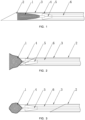
- FIGs. 1-3 illustrate three states of a minimally invasive interventional surgical instrument according to an exemplary embodiment of the present invention.
- the minimally invasive interventional surgical instrument comprises a tissue cutter, a delivery sheath 3, a pusher 6, and a connector 4.
- the tissue cutter may comprise a tissue cutting stent 1 and a first reefing thread 5.
- the contracted tissue cutting stent 1 is accommodated within the delivery sheath 3.
- the delivery sheath 3 has a proximal opening at its proximal end and a distal opening at its distal end.
- the delivery sheath 3 may be tube-shaped.
- the delivery sheath 3 may penetrate the body of a patient along the axial direction of the tube, and the openings at the both ends of the tube form the proximal opening and the distal opening, respectively.
- proximal and distal herein are relative to the surgeon performing the minimally invasive interventional surgery with the minimally invasive interventional instrument, wherein the proximal end is close to the surgeon and the distal end is away from the surgeon.
- the connector 4 is connected between the pusher 6 and the tissue cutting stent 1.
- the connector 4 may be connected to the tissue cutting stent 1 in a detachable, non-detachable, self-releasable manner and so on, more specifically to the proximal end of the tissue cutting stent 1 which will be described in detail below.
- the detachable connection includes snap connection, threaded connection, pin insertion and so on.
- the beneficial effect of the detachable connection is that the tissue cutting stent 1 can be disassembled from the connector 4 after the use, and only the tissue cutting stent 1 is required to be replaced each time for use.
- the non-detachable connection includes welding, bonding, interference fit and so on.
- the self-releasable connection means that the connector 4 can be self-released from the tissue cutting stent 1 when a constraint force on the connector 4 is removed.
- the constraint force may be a radial restraining force exerted on it by the delivery sheath 3.
- the constraint force is removed when the connector 4 is pushed out of the delivery sheath 3, thereby allowing the connector 4 to be released from the tissue cutting stent 1.
- the self-releasable connection is suitable for the case where the tissue cutting stent 1 remains in the body after resecting and wrapping the lesioned tissues which can be subsequently found and taken out along the first reefing thread 5 by a surgery, or degrade spontaneously after long-term implantation as needed.
- the pusher 6 extends into the delivery sheath 3 from the proximal opening of the delivery sheath 3, and is used to push the tissue cutting stent 1 out from the distal opening of the delivery sheath 3.
- the tissue cutting stent 1 may be pushed completely or partially out of the delivery sheath 3 via the distal opening.
- the pusher 6 may also push a portion or whole of the connector 4 out of the body.
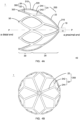
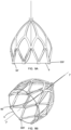
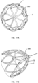
- FIGs. 4A-4C and FIG. 5 all illustrate a tissue cutting stent 1 according to an exemplary embodiment, wherein the tissue cutting stent 1 in FIGs. 4A-4C is in an expanded state and the tissue cutting stent 1 in FIG. 5 is in a contracted state.
- the tissue cutting stent 1 is expandable in the radial direction.
- the expanded tissue cutting stent 1 is loudspeaker-shaped gradually opening from the proximal end to the distal end.
- the expanded tissue cutting stent 1 forms a loudspeaker-shaped accommodating space 40.
- the accommodating space 40 is used to accommodate the resected tissue.
- the tissue cutting stent 1 before expansion may be elongated, which facilitates to be accommodated within the delivery sheath 3.
- the tissue cutting stent 1 is provided with a plurality of first threading holes 50 at the distal end thereof.
- the plurality of first threading holes 50 are arranged along the circumferential direction of the tissue cutting stent 1.
- the first reefing thread 5 passes through the plurality of first threading holes 50.
- the first reefing thread 5 has opposite first and second ends, and the first end thereof is secured to one of the plurality of first threading holes 50. The second end thereof may be used for tighten the opening of the tissue cutting stent 1 by
- the tissue cutting stent 1 may include a fixed part 10, a support part 20, and an expansion part 30.
- the fixed part 10, the support part 20 and the expansion part 30 are arranged sequentially along the axial direction of the tissue cutting stent 1 (i.e., the extension direction of the axis P-P as shown in the drawings).
- the fixed part 10 is located at the proximal end of the tissue cutting stent 1
- the expansion part 30 is located at the distal end of the tissue cutting stent 1.
- the support part 20 is connected between the fixed part 10 and the expansion part 30.
- the proximal end of the support part 20 is connected to the fixed part 10.
- the proximal end of the expansion part 30 is connected to the distal end of the support part 20.
- the expansion part 30 and the support part 20 are expandable along the radial direction.
- the fixed part 10 does not have an expansion function, and accordingly under the constraint of the fixed part 10, the expanded expansion part 30 and the support part 20 are loudspeaker-shaped gradually opening from the proximal end to the distal end.
- the ratio of the outer diameter of the distal end of the loudspeaker to the outer diameter of the proximal end thereof is greater than 5:1.
- the expanded expansion part 30 and the support part 20 together form the loudspeaker-shaped accommodating space 40.
- the expansion part 30 and the support part 20 may be made of any material having expansion and contraction capacities, such as an elastic material.
- the expansion part 30 and the support part 20, when not subject to an external force, are loudspeaker-shaped.
- the elastic material can be compressed, thus the expansion part 30 and the support part 20 can be contracted to the shape as shown in FIG. 5 , thereby accommodated within the delivery sheath 3.
- the expansion part 30 and the support part 20 are in a web-like structure overall. Even though the material itself, which forms the web-like structure, may not be elastic, the web-like structure may allow the expansion part 30 and the support part 20 to expand and contract.
- the expansion part 30 and the support part 20 may be made of a shape-memory material (such as, a memory alloy).
- the expansion part 30 and the support part 20, when not subject to an external force, are loudspeaker-shaped. When subject to a radially inward pressure, the expansion part 30 and the support part 20 may be contracted to the shape as shown in FIG. 5 , thereby accommodated within the delivery sheath 3.
- the expansion part 30 and the support part 20 may be made of a deformable material. After the tissue cutting stent 1 is placed into the human body, a positive pressure may be exerted within the accommodating space 40, such as inflating the accommodating space 40 or injecting liquid to the accommodating space 40, to make the expansion part 30 and the support part 20 expand.
- the expansion part 30 and the support part 20 may also be of the web-like structure made of the elastic material. Only one style web-like structure is shown in FIGs. 4A-4C , and in the other embodiments not shown, the web-like structure may have other styles as long as its function can be realized.
- the expansion part 30 and the support part 20 may have a self-expanding function.
- the expansion part 30 and the support part 20 may not have the self-expanding function, but expands to a desired shape by an external force (such as a positive pressure to be described below) after being pushed out of the delivery sheath 3.
- an external force such as a positive pressure to be described below
- the external force can help the tissue cutting stent expand in more dense tissues and organs (such as dense breast, prostate and so on).
- the plurality of threading holes 50 may be provided at the distal end of the expansion part 30.
- the plurality of threading holes 50 may be provided uniformly along the circumferential direction of the expansion part 30 at its distal end.
- the plurality of threading holes 50 may also be provided at unequal intervals.
- the fixed part 10 is used to connect to the pusher 6.
- the fixed part 10 may have a center hole 12.
- the center hole 12 may pass through the fixed part 10 along the axial direction.
- the center hole 12 is communicated with the accommodating space 40.
- the first reefing thread 5 may extend into the accommodating space 40 through the center hole 12, wherein the section of the first reefing thread 5 extending into the accommodating space 40 passes through the plurality of threading holes 50, as shown in FIGs. 6A-6B .
- the distal end of the expansion part 30 gradually close, thereby wrapping the tissues that have entered into the accommodating space 40, as shown in FIGs. 3 and 7 .
- the surgeon may take them out immediately, or leave them temporarily in the body, or allow them to degrade spontaneously after long-term implantation as needed.
- the fixed part 10 may not be provided with the center hole 12.
- the first reefing thread 5 may extend into the accommodating space 40 from a position of the support part 20 close to the fixed part 10.
- the tissue cutter may be contracted into the delivery sheath 3 before put into the human body, and be pushed out of the delivery sheath 3 by the pusher 6 after entering the human body.
- the tissue cutter after being pushed out may self-expand or expand under the positive pressure exerted within the accommodating space 40.
- the delivery sheath 3 may have a very small diameter to put the tissue cutter into the human body.
- the opening of the tissue cutter may be closed by the first reefing thread to wrap the tissues within it.
- the tissue cutter in the process of its closing may compress the wrapped tissues to a certain extent, so that only a minor incision is required to take the tissue cutter and the resected tissues out.
- both the surgical instrument and resection action in the present invention are simple to allow the completion of the surgery with imaging devices. In this way, it is possible to conduct accurate resection of lesioned tissues and achieve reduction of damages to the normal tissues and organs.
- tissue cutter provided in the present invention to perform the minimally invasive surgery for resecting lesioned tissues, because of the minor incision created on the body surface and the target tissues and organs of the human, and accurate resection of only lesioned tissues, more normal tissues and organs are kept, the damages caused to patients are less, their recovery is faster and their long-term quality of life can be ensured.
- the support part 20 comprises a plurality of support segments 200, and the support segments 200 are provided along the circumferential direction of the tissue cutting stent 1.
- Each of the support segments 200 has a root end 210 and a tip end 220.
- the root end 210 is connected to the fixed part 10.
- the tip end 220 is connected to the expansion part 30.
- each support segment 200 is Y-shaped, thus each support segment comprises one root end 210 and two tip ends 220, referring to FIGs. 4A-4B .
- the root ends 210 of the plurality of support segments 200 are clustered with each other, and in any two adjacent support segments, one tip end 220 of one support segment is connected to one tip end 220 of the other support segment.
- each support segment 200 may comprise one first support segment 22 and a pair of second support segments 24.
- a plurality of first support segments 22 are radial along a direction from the proximal end to the distal end. The angle between adjacent first support segments 22 may be equal or unequal.
- the proximal ends of the plurality of first support segments 22 are connected to the fixed part 10.
- the distal ends of the plurality of first support segments 22 are connected to the second supports 24.
- a pair of second support segments 24 comprised in each support segment 200 are called as second left support segment 242 and second right support segment 244, respectively.
- the second left support segment 242 of one support segment 200 is connected to the second right support segment 244 of the other support segment 200 at the tip end 220. That is, for each pair of second support segments 24, the second left support segment 242 therein and the second right support segment 244 of the left-side adjacent support segment 200 are connected to each other at the tip end 220, while the second right support segment 244 therein and the second left support segment 242 of the right-side adjacent the support segment 200 are connected to each other at the tip end 220. Accordingly, the expanded support part 20 diverges in a tree-like manner along the direction from the proximal end to the distal end.
- the axial length of the support segment 200 can be extended, which in turn can make the tissue cutting stent 1 have large enough radial dimension and accommodating space so as to resect a sufficient number of lesioned tissues each time.
- the support part 20 may have more uniformly dimensioned meshes along the axial direction to avoid the tissues wrapped within it from penetrating outside the support part 20 via the larger meshes, resulting in that the radial dimension of the support part 20 in the closed state is not uniform at each position.
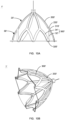
- each of the plurality of support segments 200' is rod-shaped, as shown in FIGs. 10A-10B .
- the plurality of support segments 200' are radial from the root ends to the tip ends as if an umbrella bone.
- the axial dimension of the expanded stent is shortened, the volume of the accommodating space 42 is reduced and the number of tissues that can be resected in once time is decreased, but at the same time, the axial dimension of the contracted tissue cutting stent 1' can be shortened and the release distance of the stent be reduced (the distance between the delivery sheath and the target lesions before the release of the stent), which is suitable for the case where the lesions are closer to the edge of the tissues and organs.
- the surgeon may choose an appropriate tissue cutting stent as needed.
- the expansion part may have a single layer or multiple layers of annular structure.
- Each layer of annular structure comprises a plurality of expansion segments, and the plurality of expansion segments are provided along the circumferential direction of the tissue cutting stent.
- Each expansion segment is V-shaped, so that each expansion segment has two open ends and one pointed end. The open ends of adjacent two expansion segments in each layer of annular structure are connected.
- the expansion part 30 has a single layer of annular structure.
- the expansion part 30 comprises a plurality of expansion segments 300.
- the expansion segments 300 are V-shaped with the opening thereof facing the proximal end, that is, two open ends 310 of each expansion segment 300 are located at the proximal end of the expansion segment 300 and one pointed end 320 of each expansion segment 300 is located at the distal end of the expansion segment 300.
- the two sides of the V-shape are noted as left expansion segment 32 and right expansion segment 34, respectively.
- the left expansion segment 32 and the right expansion segment 34 are connected to each other at the distal end to form the pointed end 320.
- the proximal ends of the left expansion segment 32 and the right expansion segment 34 are spaced apart from each other to form two open ends 310, but the open ends 310 of adjacent two expansion segments 300 are connected to each other to form the ring structure. And, the open ends 310 are connected to the tip ends 220 of the plurality of support segments 200 in one-to-one correspondence.
- the second left support segment 242 therein is connected to the left expansion segment 32
- the second right support segment 244 therein is connected to the right expansion segment 34.
- a pair of second support segments i.e., the second left support segment 242 and the second right support segment 244
- a pair of expansion segments i.e., the left expansion segment 32 and the right expansion segment 34
- adjacent small rings are connected to each other to form a large ring. In this way, a stable structure can be obtained.
- each expansion section 300 is provided with one first threading hole 50.
- the threading holes 50 may be uniformly distributed at the distal end of the expansion part 30.
- each support segment 200' has only one tip end 220', two open ends 310' of each expansion segment 300' are respectively connected to two support segments 200', while each support segment 200' is connected to one of the open ends 310' of adjacent two expansion segments 300', respectively.
- the multiple layers of annular structures may be provided in the axial direction. That is, in adjacent two layers of annular structure, the open ends of one layer of annular structure and the pointed ends of the other layer of annular structure are connected in one-to-one correspondence.
- FIGs. 10A-10B if one more layer of annular structure is added, it can be considered that two pointed ends of each expansion segment comprised in the added layer of annular structure are connected to two pointed ends 320' of two expansion segments 300', respectively. Of course, more layers of annular structure may be added.
- the open ends 310' of the layer of annular structure closest to the support segments 200' are connected to the tip ends 220' of the plurality of support segments 200' in one-to-one correspondence, and the pointed end of each expansion segment of the layer of annular structure farthest from the support segments 200' is provided with one first threading hole.
- the expansion part of the multiple layers of annular structure may also be combined with the support part with the Y-shaped support segments.
- the expansion part 30 and the support part 20 have a thinner thickness along the radial direction of the tissue cutting stent 1, thus the expansion part 30 and the support part 20 can expand and contract along the radial direction.
- the width of the expansion part 30 and the support part 20 is somewhat greater than the thickness thereof.
- the width here refers to the dimension of each expansion segment 300 of the expansion part 30 as well as that of each first support segment 22 and second support segment 24 of the support part 20 along the circumferential direction of the tissue cutting stent 1.
- the threading holes 50 extend along the radial direction of the tissue cutting stent 1, as shown in FIGs. 6A-6B , more beneficial to ensure the adequate mechanical strength of the pointed ends 320 provided with the threading holes 50.
- the fixed part 10, the support part 20 and the expansion part 30 are formed by cutting a tubular product in the axial direction.
- the tubular product may have a thinner wall.
- the formation of the tissue cutting stent 1 by cutting the tubular product is critical for the following reasons: the thin stent structure formed by cutting the tubular product provides not only the strongest radial bracing force but also sufficient rigidity to ensure that the tissue cutting stent 1 does not twist while it advances within the tissues and organs, thus enabling smooth expansion to a predetermined dimension in solid organs.
- an integrated stent structure ensures minimal outer diameter of the entire stent after contraction, reducing the risk of puncture; and it is more suitable for maintaining the shape while advancing in solid organs with resistance.
- the first end of the first reefing thread 5 may be secured to the starting threading hole 52 in the plurality of threading holes 50. After passing through the other threading holes, the first end may extend from inside the accommodating space 40 via the center hole 12 on the fixed part 10 to the outside of the body.
- the first reefing thread 5 is connected to all the other threading holes in a manner of sliding connection. After the surgeon pulls the first reefing thread 5 outside the body to close the tissue cutting stent 1, the first reefing thread 5 remains connected to the tissue cutting stent 1.
- first reefing thread 5 may be threaded through the tissue cutting stent 1 in various manners.
- the first reefing thread 5 adopts a Z-shaped threading manner. As shown in FIGs. 6A-6B , the first end of the first reefing thread 5 is secured to the starting threading hole 52, and the middle section of the first reefing thread 5 sequentially passes through the other threading holes along the circumferential direction. Preferably, the middle section of the first reefing thread 5 passes through the other threading holes in the same direction. In this way, when the tissue cutting stent 1 is in the closed state, adjacent two first threading holes 50, because of the effect of the first reefing thread 5, may not fit perfectly along the circumferential direction of the tissue cutting stent 1, and also have a tendency to be separated from each other along the radial direction.
- the next threading hole tends to be located radially outside the previous threading hole, and the two are spaced apart along the circumferential direction, thereby the first reefing thread 5 when tightening has a plurality of bends at the plurality of first threading holes 50, so that it has certain self-locking effect, and accordingly the tissue cutting stent 1 is not likely to expand easily.
- the middle section of the first reefing thread 5 passes through the other threading holes in a crisscross manner, so that the first reefing thread 5 forms a web-like structure at the distal end of the tissue cutting stent 1.
- FIGs. 8A-8B one threading matter of the first reefing thread 5 to form the web-like structure is illustrated.
- the first reefing thread 5 may adopt other threading matters as long as a web-like structure can be formed.
- the advantage of this threading manner is that the web-like first reefing thread 5 at the front end can have the function of resecting the lesioned tissues while the tissue cutting stent 1 advances within the tissues and organs, facilitating to shatter the lesioned tissues. Therefore, those skilled in the art can set the mesh dimension of the web-like structure as needed to obtain the lesioned tissues in a desired degree of shattering. After shattering the tissues, the shattered tissues are wrapped in the tissue cutting stent 1, which facilitates the tissues to be compressed smaller after the tissue cutting stent 1 is closed, thereby further ensuring that the incision has a smaller dimension.
- the pointed ends 320' of the expansion segments rotates by a predetermined angle in a plane perpendicular to the axial direction P-P of the tissue cutting stent 1 with respect to the pointed ends 320 in the preceding embodiment, to make the first threading holes 50' on the pointed ends 320' at the predetermined angle to the radial direction of the tissue cutting stent 1.
- the first threading holes 50 on the pointed ends 320 extend along the radial direction of the tissue cutting stent 1.
- 9A-9B illustrate the case of the rotation of 90 degrees with respect to the pointed ends 320, where the rotated threading holes 50' extend along the circumferential direction of the tissue cutting stent 1.
- the first reefing thread 5 bends less after passing through all the first threading holes 50', thus when the first reefing thread 5 moves relative to the first threading holes 50', it encounters less resistance.
- the tissue cutting stent cannot fully expand to a desired dimension due to the frictional resistance between the first reefing thread 5 and the first threading holes 50' when the tissue cutting stent expands from the contracted state to the expanded state.
- the pointed ends 320' may also rotate at any other angle.
- This threading manner of the first reefing thread 5 is referred to herein as annular threading manner.
- the lesioned tissues can be resected primarily using the first reefing thread 5 while it advances and aided by the edge of the distal end of the tissue cutting stent 1.
- the tissue cutting stent 1 may be provided to be electrically conductive.
- the first reefing thread 5 is also electrically conductive.
- the tissue cutting stent 1 and the first reefing thread 5 may form a positive electrode in an electrical circuit, which forms a monopolar electric knife circuit together with a negative plate affixed to the body surface, thereby electrical treatment such as electro-resection, electrocoagulation or radiofrequency ablation on the lesioned tissues can be performed while the tissue cutting stent 1 advances and during its expansion.
- the delivery sheath 3 is electrically conductive, which acts as one electrode, and the tissue cutting stent 1 and the first reefing thread 5 act as the other electrode, thereby forming a bipolar electric knife circuit.
- the outer surface of the tissue cutting stent 1 may be covered with an insulating outer layer 60, as shown in FIG. 12 .
- the connector 4 and the pusher 6 are insulated from the delivery sheath 3.
- the connector 4 and the pusher 6 may be made of an insulating material, or an insulating layer may be formed on the outer surfaces of the connector 4 and the pusher 6 as well.
- the puncture needle 2 is electrically conductive, which acts as one electrode, and the tissue cutting stent 1 and the first reefing thread 5 act as the other electrode, thus forming the bipolar electric knife circuit.
- the delivery sheath 3 may be insulating.
- the delivery sheath 3 may be made of an insulating material or an insulating layer may also be formed on the outer surface of the delivery sheath 3.
- electrocoagulation may be performed for hemostasis during or after tissue resection.
- the bipolar electric knife circuit has more stable electrical properties than the monopolar electric knife circuit.
- the ablation treatment may be performed at the external side of needle passage or resection area to kill locally scattered tumor cells that are not resected.
- the support part 200 may be provided with a plurality of second threading holes 70, and the plurality of second threading holes 70 are arranged along the circumferential direction of the tissue cutting stent. Along the axial direction, the plurality of second threading holes 70 may be provided in the middle of the support part 200 or at the distal end of the support part 200.
- the tissue cutter further comprises a second reefing thread 7, and the second reefing thread 7 passes through the plurality of second threading holes 70.
- the second reefing thread 7 may be pulled outside the body when the tissue cutting stent goes into or is in the closed state to further reduce the radial dimension of the closed tissue cutter and compress the resected tissues within the accommodating space, so that the closed tissue cutter can be taken out through a minor incision.
- the second reefing thread 7 sequentially passes through the plurality of second threading holes 70 along the circumferential direction.
- the second reefing thread 7 may pass through each second threading hole 70 along the same direction.
- the second reefing thread 7 may also pass through each second threading hole 70 along a different direction, for example the second reefing thread 7 may pass through adjacent second threading holes 70 along the different directions.
- One end of the second reefing thread 7 is secured to one of the second threading holes 70, and the other end thereof passes through the accommodating space. In the case where the proximal end of the tissue cutting stent has a center hole, the other end thereof may pass out through the center hole, as shown in the drawings.
- the other end may pass out at any appropriate location at the proximal end of the tissue cutting stent.
- the second reefing thread 7 may also pass through the second threading holes 70 in other threading manners.
- the second reefing thread 7 may adopt any of the threading manners for the first reefing thread 5.
- the advantage of the second reefing thread 7 sequentially passing through the plurality of second threading holes 70 along the circumferential direction is that the second reefing thread 7 does not affect the utilization of the accommodating space.
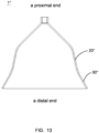
- FIG. 13 schematically illustrates a tissue cutting stent 1" according to another exemplary embodiment of the present invention, wherein the expansion part 30" of the tissue cutting stent 1" is gradually opens from its proximal end to its distal end.
- the expansion part 30" is at an angle to the overall direction of advancing (i.e. advancing along the direction of the axis P-P), thereby the expansion part 30" may expand in advance when the expansion part 30" has stretched out of the delivery sheath and the support part 20" not yet fully stretched out of the delivery sheath, to conduct preliminary resection of the tissues, thereby reducing the radial resistance to the tissue cutting stent in the process of its releasing and expansion and forming a more stable expansion dimension.
- the intersection angles between various sections of the expansion part 30" and the axis P-P may be the same or different. In the case where the intersection angles are different, preferably, the angles between the expansion part 30" and the axis P-P may gradually increase along the direction from the proximal end to the distal end. It is more favorable for the expansion part 30" to expand and open within the tissues and organs.
- the expansion part 30" bend outward with respect to the support part 20".
- the smaller angle between the support part 20" and the axis P-P can be ensured that the tissue cutting stent 1" has a sufficient axial dimension to form a sufficiently deep accommodating space.
- the angle between the expansion part 30" and the axis P-P is larger, the radial resistance to the expansion part 30" and the support part 20" in the process of expansion can be reduced to form a more stable expansion dimension.
- any of the aforesaid tissue cutting stents can further comprise a membrane.
- FIG. 12 illustrates the structure covered with the membrane, wherein the membrane may cover the support part 20 and the expansion prat 30.
- the membrane may comprise an inner layer, or an outer layer, or the both.
- the inner layer covers the inner surfaces of the support part 20 and the expansion part 30.
- the outer layer 60 covers the outer surfaces of the support part 20 and the expansion part 30.
- the electric ablation treatment may continue to be exerted to inactivate the local tissues not resected.
- the outer layer may be an electrically conductive layer that participates in the ablation
- the inner layer may be an insulating layer that protects the biological properties of the resected tissues from being destroyed for use in pathological diagnosis.
- both the inner and outer layers may be insulating layers.
- the inner and outer layers may be the layers of the same material, resulting in simple processing technics and less cost.
- the fixed part 10 is provided with a through-hole 14, and the through-hole 14 is communicated with the center hole 12, as shown in FIG. 12 .
- airways may be formed within the delivery sheath 3 and on the outer side of the tissue cutting stent 1.
- positive pressure gas may be delivered into the delivery sheath 3 from the proximal end and into the accommodating space via the through-hole 14 and the center hole 12. Since the front end of the tissue cutting stent 1 is located within the tissues and organs, the positive pressure gas can make the support part 20 and the expansion part 30 expand.
- a negative pressure may be created within the delivery sheath 3 and the accommodating space, thereby drawing in more tissues to be resected.
- the interventional surgical instrument further comprises a pneumatic device, and the pneumatic device is used to inject air to the delivery sheath 3 and/or extract air from the delivery sheath 3 to create the positive and negative pressures as described above.
- the tissue cutting stent 1 when the tissue cutting stent 1 is in a push-out position, as shown in FIG. 2 , the tissue cutting stent 1 does not separate from the delivery sheath 3 completely, but abuts against the edge of the distal opening of the delivery sheath 3. Since the fixed part 10 is continuously kept within the delivery sheath 3, no leakage of cellular tissues through the through-hole 14 is caused.
- the distal end of the delivery sheath 3 may be provided with water-permeable holes (not shown), and the tissue cutting stent 1 may be covered with a water-resisting membrane.
- the space between the water-resisting membrane and the delivery sheath is communicated with the outside via the water-permeable holes.
- electrically conductive water may be delivered into the tissues and organs via the delivery sheath 3 and the water-permeable holes, thereby improving the electrical conductivity of the electrodes and making the electrical conductivity of the tissues and organs more uniform, which facilitates the execution of electro-resection.
- the temperature of the local tissues can be reduced during the electro-resection.
- the tissue cutting stent 1 If the temperature of the surrounding tissues is too high in the process of the electro-resection, they may adhere to the tissue cutting stent 1. With the delivery of fluid, not only the temperature of the tissues and the tissue cutting stent 1 can be lowered, but also the tissues can be moisturized so as to prevent the tissue cutting stent 1 from being adhered to the tissues.
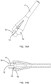
- FIGs. 14A-14B also illustrate a connector 4 according to an embodiment of the invention.
- the connector 4 may be provided with a plurality of snap clips 42 at the distal end, and the plurality of snap clips 42 arranged along the circumferential direction. A gap is formed between adjacent snap clips 42, thereby allowing the snap clips 42 to have a certain degree of elasticity.
- the fixed part 10 may be provided with openings 16 corresponding to the snap clips 42. When a radially outward force is exerted on the snap clips 42, the snap clips 42 may open and snap into the openings 16.
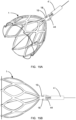
- FIGs. 15A-15B illustrate a connector 4' according to another embodiment of the invention.
- the connector 4' comprises a plurality of elastic locking claws 44, and the outer side of the fixed part 10 of the tissue cutting stent 1 is provided with a plurality of slots 18.
- the plurality of elastic locking claws 44 are compressed along the radial direction, that is, the elastic locking claws 44 are subjected to a radially inward force exerted by the delivery sheath 3.
- the plurality of elastic locking claws 44 snap with the plurality of slots 18, respectively.
- the plurality of elastic locking claws When the plurality of elastic locking claws are outside the delivery sheath 3, the plurality of elastic locking claws 44 are separated from the plurality of slots 18 along the radial direction. As a result, after the pusher 6 pushes the connector 4 out of the delivery sheath 3, the radial force exerted by the delivery sheath 3 is removed, thereby making the connector 4 separated from the tissue cutting stent 1.
- At least one of the puncture needle 2, the delivery sheath 3 and the first reefing thread 5 is provided with scales.
- the puncture needle 2 and the delivery sheath 3 may have scales on their outer surfaces which can help the surgeon to determine how deep they have entered the tissues and organs.
- the first reefing thread 5 may have scales on the section remaining outside the body, which can prompt the surgeon the current degree of closing of the tissue cutting stent 1.
- the minimally invasive interventional surgical instrument may be used in following ways.
- the minimally invasive interventional surgical instrument Under the guidance of imaging devices (such as CT), the minimally invasive interventional surgical instrument reaches the target tissues via a puncture route. It may be also reach the vicinity of the target tissues via a natural cavity, and later approach the lesions with local puncturing.
- imaging devices such as CT
- the delivery sheath 3 may be delivered inside the patients' body by the puncture needle 2, or re-enters via the incision after the puncture needle 2 is withdrawn, thereby making it possible to use the puncture needle 2 with a smaller diameter.
- the tissue cutting stent 1 or 1' is pushed out of the delivery sheath 3 by the pusher 6 and then may spread with self-expanding, or under the positive pressure, it may reach an expended state in the tissues and organs, as shown in FIG. 2 .
- the tissue cutting stent 1 or 1' may be energized to reduce the expansion resistance. Since the distal end of the tissue cutting stent 1 or 1' separates from the delivery sheath 3, the distal end of the tissue cutting stent 1 or 1' spreads firstly, and electrification allows the distal end to have a resecting effect, i.e., resecting while spreading.
- the tissue cutting stent 1 or 1' After the tissue cutting stent 1 or 1' expands, it may continue to be pushed straight forward, and with mechanical resecting and / or electrical resecting, to enclose the lesioned tissues into the accommodating space of the tissue cutting stent 1 or 1'. It may rotate and draw the lesioned tissues during the process of resecting to increase the mechanical resecting intensity.
- the accommodating space In the process of resecting, the accommodating space may continue to be kept under the negative pressure by the aforesaid pneumatic device to draw and fix more tissues into the accommodating space.
- electro-resection mode or electrocoagulation mode may be used alone, or a combination of electro-resection and electrocoagulation modes may be used to meet different needs for resection and hemostasis.
- the first reefing thread 5 is lifted after the lesioned tissues are enclosed in the accommodating space, and whether the tissue cutting stent 1 or 1' has been fully closed may be determined based on the length of the lifting. In the process of lifting, different electrosurgical modes such as electro-resection, electrocoagulation or vascular closure may continue to be exerted. After the tissue cutting stent 1 or 1' is completely closed, electric ablation may continue to be exerted to inactivate the local tissues not resected.
- the tissue cutting stent 1 or 1' may be retracted into the delivery sheath 3 by lifting the pusher 6 after the tissue cutting stent 1 or 1' is completely closed, which allows the tissue cutting stent 1 or 1' to be completely wrapped and then removed from the body, reducing the risk of lesion metastasis.
- the tissue cutting stent 1 or 1' may be directly lifted after being secured to the delivery sheath 3 and the pusher 6 to take all the tissues out.
- the puncture needle 2 may be left in the body for subsequent processing, such as injection of hemostatic drugs and so on.
- the pusher 6 may be continuously pushed until the connector 4' is pushed out of the delivery sheath 3 to be unlocked. After the puncture needle 2, the delivery sheath 3, the connector 4' and the pusher 6 are retracted, the tissue cutting stent 1 or 1' and the first reefing thread 5 are retained in the body which may be taken out by other surgeries. If the tissue cutting stent 1 or 1' is self-degrading, after the first reefing thread 5 is unlocked from the tissue cutting stent 1 or 1', the first reefing thread 5 can be withdrawn from the body, or the portion of the first reefing thread 5 left outside the stent can be cut off by using a cutting device.
Landscapes
- Health & Medical Sciences (AREA)
- Surgery (AREA)
- Life Sciences & Earth Sciences (AREA)
- Engineering & Computer Science (AREA)
- Veterinary Medicine (AREA)
- Molecular Biology (AREA)
- Nuclear Medicine, Radiotherapy & Molecular Imaging (AREA)
- Public Health (AREA)
- Biomedical Technology (AREA)
- Heart & Thoracic Surgery (AREA)
- Medical Informatics (AREA)
- General Health & Medical Sciences (AREA)
- Animal Behavior & Ethology (AREA)
- Otolaryngology (AREA)
- Plasma & Fusion (AREA)
- Physics & Mathematics (AREA)
- Pathology (AREA)
- Prostheses (AREA)
- Surgical Instruments (AREA)
- Media Introduction/Drainage Providing Device (AREA)
Claims (28)
- Gewebeschneider, umfassend einen Gewebeschneidestent (1, 1', 1"), der in einer radialen Richtung expandierbar ist, und einen ersten Refffaden (5);wobei der expandierte Gewebeschneidestent (1, 1', 1") lautsprecherförmig ist, graduell öffnend von einem proximalen Ende zu einem distalen Ende, und ein lautsprecherförmiger Aufnahmeraum (40) im Inneren des expandierten Gewebeschneidestents (1, 1', 1") ausgebildet ist, wobei der Gewebeschneidestent (1, 1', 1") mit einer Vielzahl von ersten Einfädellöchern (50, 50') an dem distalen Ende versehen ist, wobei die Vielzahl von ersten Einfädellöchern (50, 50') entlang einer Umfangsrichtung des Gewebeschneidestents (1, 1', 1") angeordnet ist; undder erste Refffaden (5) durch die Vielzahl von ersten Einfädellöchern (50, 50') hindurchgeht, wobei der erste Refffaden (5) ein erstes und ein zweites Ende, die gegenüberliegend sind, aufweist, wobei das erste Ende an einem Anfangseinfädelloch (52) in der Vielzahl von ersten Einfädellöchern (50, 50') befestigt ist;wobei der Gewebeschneidestent (1, 1', 1") ein festes Teil (10), ein Stützteil (20, 20', 20") und ein Expansionsteil (30, 30', 30") umfasst, wobei das feste Teil (10), das Stützteil (20, 20', 20") und das Expansionsteil (30, 30', 30") nacheinander entlang der axialen Richtung des Gewebeschneidestents (1, 1', 1") von dem proximalen Ende zu dem distalen Ende verbunden sind, wobei die Vielzahl von ersten Einfädellöchern (50, 50') an dem Expansionsteil (30, 30', 30") bereitgestellt ist, wobei das Stützteil (20, 20', 20") und das Expansionsteil (30, 30', 30") entlang der radialen Richtung expandierbar sind, um den Aufnahmeraum (20, 20', 20") auszubilden; unddadurch gekennzeichnet, dass das Stützteil (20, 20', 20") mit einer Vielzahl von zweiten Einfädellöchern (70) versehen ist, wobei die Vielzahl von zweiten Einfädellöchern (70) entlang der Umfangsrichtung des Gewebeschneidestents (1, 1', 1") angeordnet ist und der Gewebeschneider ferner einen zweiten Refffaden (7) umfasst, wobei der zweite Refffaden (7) durch die Vielzahl von zweiten Einfädellöchern (70) hindurchgeht.
- Gewebeschneider nach Anspruch 1, dadurch gekennzeichnet, dass das Expansionsteil (30, 30', 30") und das Stützteil (20, 20', 20") insgesamt in einer netzartigen Struktur vorliegen.
- Gewebeschneider nach Anspruch 1, dadurch gekennzeichnet, dass das Stützteil (20, 20') eine Vielzahl von Stützsegmenten (200, 200'), die entlang der Umfangsrichtung des Gewebeschneidestents (1, 1') bereitgestellt ist, umfasst, wobei jedes der Vielzahl von Stützsegmenten (200, 200') ein Ansatzende (210) und ein Spitzenende (220, 220') aufweist, wobei das Ansatzende (210) mit dem festen Teil (10) verbunden ist und das Spitzenende (220, 220') mit dem Expansionsteil (30, 30') verbunden ist.
- Gewebeschneider nach Anspruch 3, dadurch gekennzeichnet, dass das Expansionsteil (30, 30') eine einzelne Schicht oder mehrere Schichten einer ringförmigen Struktur aufweist, jede Schicht der ringförmigen Struktur umfassend eine Vielzahl von Expansionssegmenten, die entlang der Umfangsrichtung des Gewebeschneidestents (1, 1') bereitgestellt sind, wobei jedes Expansionssegment V-förmig ist, um zu veranlassen, dass jedes Expansionssegment zwei offene Enden (310, 310') und ein spitzes Ende (320, 320') aufweist, wobei die offenen Enden (310, 310') von zwei angrenzenden Expansionssegmenten in jeder Schicht der ringförmigen Struktur verbunden sind, wobeiin dem Fall, wo das Expansionsteil (30, 30') eine einzelne Schicht der ringförmigen Struktur aufweist, die offenen Enden (310, 310') in einer Eins-zu-eins-Entsprechung mit den Spitzenenden (220, 220') der Vielzahl von Stützsegmenten (200, 200') verbunden sind, wobei das spitze Ende (320, 320') jedes Expansionssegments mit einem ersten Einfädelloch (50, 50') versehen ist;in dem Fall, wo das Expansionsteil (30, 30') mehrere Schichten der ringförmigen Struktur aufweist, die mehreren Schichten der ringförmigen Struktur entlang der axialen Richtung bereitgestellt sind, wobei in zwei angrenzenden Schichten der ringförmigen Struktur die offenen Enden (310, 310') einer Schicht der ringförmigen Struktur und die spitzen Enden (320, 320') der anderen Schicht der ringförmigen Struktur in der Eins-zu-eins-Entsprechung verbunden sind; und wobei die offenen Enden (310, 310') der Schicht der ringförmigen Struktur, die den Stützsegmenten (200, 200') am nächsten sind, in der Eins-zu-eins-Entsprechung mit den Spitzenenden (220, 220') der Vielzahl von Stützsegmenten (200, 200') verbunden sind, und die spitzen Enden (320, 320') jedes Expansionssegments der Schicht der ringförmigen Struktur, die am weitesten von den Stützsegmenten (200, 200') entfernt sind, alle mit einem ersten Einfädelloch (50, 50') versehen sind.
- Gewebeschneider nach Anspruch 3, dadurch gekennzeichnet, dass jedes der Vielzahl von Stützsegmenten (200, 200') stabförmig ist, wobei, in einem expandierten Stützteil, die Vielzahl von Stützsegmenten (200, 200') radial von den Ansatzenden (210) zu den Spitzenenden (220, 220') sind.
- Gewebeschneider nach Anspruch 3, dadurch gekennzeichnet, dass, in einem expandierten Stützteil, jedes der Vielzahl von Stützsegmenten (200) Y-förmig ist, um zu veranlassen, dass jedes der Vielzahl von Stützsegmenten (200) ein Ansatzende (210) und zwei Spitzenenden (220) umfasst, wobei die Ansatzenden (210) der Vielzahl von Stützsegmenten (200) miteinander gruppiert sind und, in beliebigen zwei angrenzenden Stützsegmenten (200), ein Spitzenende (220) eines Stützsegments (200) mit einem Spitzenende (220) des anderen Stützsegments (200) verbunden ist.
- Gewebeschneider nach Anspruch 4, dadurch gekennzeichnet, dass sich die spitzen Enden (320'), die mit den ersten Einfädellöchern (50') versehen sind, um einen vorgegebenen Winkel in einer Ebene senkrecht zu der axialen Richtung drehen, um zu veranlassen, dass die ersten Einfädellöcher (50') in dem vorgegebenen Winkel zu der radialen Richtung des Gewebeschneidestents (1) sind.
- Gewebeschneider nach Anspruch 1, dadurch gekennzeichnet, dass sich das Expansionsteil (30") von seinem proximalen Ende zu seinem distalen Ende graduell öffnet.
- Gewebeschneider nach Anspruch 8, dadurch gekennzeichnet, dass sich das Expansionsteil (30") in Bezug auf das Stützteil (20") radial nach außen biegt.
- Gewebeschneider nach Anspruch 1, dadurch gekennzeichnet, dass der zweite Refffaden (7) nacheinander durch die Vielzahl von zweiten Einfädellöchern (70) entlang der Umfangsrichtung hindurchgeht, wobei ein Ende des zweiten Refffadens (7) an einem der Vielzahl von zweiten Einfädellöchern (70) befestigt ist.
- Gewebeschneider nach Anspruch 1, dadurch gekennzeichnet, dass das feste Teil (10), das Stützteil (20, 20', 20") und das Expansionsteil (30, 30', 30") durch Schneiden eines rohrförmigen Produkts in der axialen Richtung ausgebildet werden.
- Gewebeschneider nach Anspruch 1, dadurch gekennzeichnet, dass das Stützteil (20, 20', 20") und das Expansionsteil (30, 30', 30") eine selbstexpandierende Funktion aufweisen.
- Gewebeschneider nach Anspruch 1, dadurch gekennzeichnet, dass das proximale Ende des Gewebeschneidestents (1, 1', 1") ein Mittelloch (12) aufweist, das entlang der axialen Richtung mit dem Aufnahmeraum (40) in Verbindung steht, und ein zweites Ende des ersten Refffadens (5) von dem Inneren des Aufnahmeraums (40) über das Mittelloch (12) herausgeht.
- Gewebeschneider nach Anspruch 13, dadurch gekennzeichnet, dass das proximale Ende des Gewebeschneidestents (1, 1', 1") ferner mit einem Durchgangsloch (14) versehen ist, und das Durchgangsloch (14) mit dem Mittelloch (12) in Verbindung steht.
- Gewebeschneider nach Anspruch 1, dadurch gekennzeichnet, dass ein mittlerer Abschnitt des ersten Refffadens (5) nacheinander durch die anderen Einfädellöcher in der Vielzahl von ersten Einfädellöchern (50, 50') entlang der Umfangsrichtung hindurchgeht.
- Gewebeschneider nach Anspruch 15, dadurch gekennzeichnet, dass der mittlere Abschnitt des ersten Refffadens (5) durch die anderen Einfädellöcher entlang der gleichen Richtung hindurchgeht.
- Gewebeschneider nach Anspruch 2, dadurch gekennzeichnet, dass ein mittlerer Abschnitt des ersten Refffadens (5) kreuzweise durch die anderen Einfädellöcher in der Vielzahl der ersten Einfädellöcher (50, 50') hindurchgeht, um zu veranlassen, dass der erste Refffaden (5) die netzartige Struktur an dem distalen Ende des Gewebeschneidestents (1, 1', 1") ausbildet.
- Gewebeschneider nach Anspruch 1, dadurch gekennzeichnet, dass der Gewebeschneidestent (1, 1', 1") ferner eine Membran umfasst, die das Stützteil (20, 20', 20") und das Expansionsteil (30, 30', 30") bedeckt.
- Gewebeschneider nach Anspruch 18, dadurch gekennzeichnet, dass die Membran eine Innenschicht und/oder eine Außenschicht (60) umfasst, wobei die Innenschicht die Innenoberflächen des Stützteils (20, 20', 20") und des Expansionsteils (30, 30', 30") bedeckt, die Außenschicht (60) die Außenoberflächen des Stützteils (20, 20', 20") und des Expansionsteils (30, 30', 30") bedeckt, die Innenschicht eine isolierende Schicht ist, die Außenschicht (60) eine elektrisch leitfähige oder isolierende Schicht ist.
- Minimalinvasives interventionelles chirurgisches Instrument,
dadurch gekennzeichnet, dass das minimalinvasive interventionelle chirurgische Instrument umfasst:den Gewebeschneider nach einem der Ansprüche 1 bis 19;eine Zuführungshülse (3), wobei der zusammengezogene Gewebeschneidestent (1, 1', 1") innerhalb der Zuführungshülse (3) aufgenommen ist, wobei die Zuführungshülse (3) an ihrem proximalen Ende eine proximale Öffnung und an ihrem distalen Ende eine distale Öffnung aufweist;einen Schieber (6); undeinen Verbinder (4, 4'), der zwischen dem Schieber (6) und dem distalen Ende des Gewebeschneidestents (1, 1', 1") verbunden ist;wobei sich der Schieber (6) von der proximalen Öffnung der Zuführungshülse (3) in die Zuführungshülse (3) hinein erstreckt, um den Gewebeschneidestent (1, 1', 1") von der distalen Öffnung der Zuführungshülse (3) herauszuschieben. - Minimalinvasives interventionelles chirurgisches Instrument nach Anspruch 20, dadurch gekennzeichnet, dass der Verbinder (4, 4') eine Vielzahl von elastischen Verriegelungsklauen (44) aufweist, wobei die Außenseite des proximalen Endes des Gewebeschneidestents (1, 1', 1") mit einer Vielzahl von Schlitzen (18) versehen ist, wobei,wo sich der Verbinder (4, 4') innerhalb der Zuführungshülse (3) befindet, die Vielzahl von elastischen Verriegelungsklauen (44) entlang der radialen Richtung zusammengedrückt wird und die zusammengedrückte Vielzahl von elastischen Verriegelungsklauen (44) jeweils in die Vielzahl der Schlitze (18) einrastet,wo sich die Vielzahl der elastischen Verriegelungsklauen (44) außerhalb der Zuführungshülse (3) befindet, die Vielzahl von elastischen Verriegelungsklauen (44) entlang der radialen Richtung von der Vielzahl der Schlitze (18) getrennt ist.
- Minimalinvasives interventionelles chirurgisches Instrument nach Anspruch 20, dadurch gekennzeichnet, dass der erste Refffaden (5) und der Gewebeschneidestent (1, 1', 1") elektrisch leitfähig sind.
- Minimalinvasives interventionelles chirurgisches Instrument nach Anspruch 22, dadurch gekennzeichnet, dass die Zuführungshülse (3) elektrisch leitfähig ist, die Außenoberfläche des Gewebeschneidestents (1, 1', 1") mit einer isolierenden Außenschicht (60) bedeckt ist und der Verbinder (4, 4') und der Schieber (6) von der Zuführungshülse (3) isoliert sind.
- Minimalinvasives interventionelles Instrument nach Anspruch 20,
dadurch gekennzeichnet, dass das distale Ende der Zuführungshülse (3) mit wasserdurchlässigen Löchern versehen ist, der Gewebeschneidestent (1, 1', 1") mit einer wasserbeständigen Membran bedeckt ist und der Raum zwischen der wasserbeständigen Membran und der Zuführungshülse (3) über die wasserdurchlässigen Löcher mit dem Äußeren in Verbindung steht. - Minimalinvasives interventionelles Instrument nach Anspruch 20,
dadurch gekennzeichnet, dass das minimalinvasive interventionelle Instrument ferner eine Punktionsnadel (2) umfasst, und die Zuführungshülse (3) in der Punktionsnadel (2) aufgenommen ist. - Minimalinvasives interventionelles Instrument nach Anspruch 25,
dadurch gekennzeichnet, dass der erste Refffaden (5) und der Gewebeschneidestent (1, 1', 1") elektrisch leitfähig sind, die Punktionsnadel (2) elektrisch leitfähig ist und die Zuführungshülse (3) isolierend ist. - Minimalinvasives interventionelles Instrument nach Anspruch 25,
dadurch gekennzeichnet, dass mindestens eines von der Punktionsnadel (2), der Zuführungshülse (3) und des ersten Refffadens (5) mit Skalen versehen sind. - Minimalinvasives interventionelles Instrument nach Anspruch 20,
dadurch gekennzeichnet, dass in dem Fall, wo das feste Teil (10) mit einem Durchgangsloch (14) versehen ist und das Durchgangsloch (14) mit dem Mittelloch (12) in Verbindung steht, das minimalinvasive interventionelle Instrument ferner eine pneumatische Vorrichtung umfasst, und die pneumatische Vorrichtung verwendet wird, um Luft in die Zuführungshülse (3) zu injizieren und/oder Luft von der Zuführungshülse (3) abzusaugen.
Applications Claiming Priority (2)
| Application Number | Priority Date | Filing Date | Title |
|---|---|---|---|
| CN202010559520.1A CN113813039A (zh) | 2020-06-18 | 2020-06-18 | 组织切取器和微创介入手术器械 |
| PCT/CN2021/098558 WO2021254189A1 (zh) | 2020-06-18 | 2021-06-07 | 组织切取器和微创介入手术器械 |
Publications (4)
| Publication Number | Publication Date |
|---|---|
| EP4154833A1 EP4154833A1 (de) | 2023-03-29 |
| EP4154833A4 EP4154833A4 (de) | 2023-10-18 |
| EP4154833C0 EP4154833C0 (de) | 2024-11-27 |
| EP4154833B1 true EP4154833B1 (de) | 2024-11-27 |
Family
ID=78911804
Family Applications (1)
| Application Number | Title | Priority Date | Filing Date |
|---|---|---|---|
| EP21826021.4A Active EP4154833B1 (de) | 2020-06-18 | 2021-06-07 | Gewebeschneider und minimalinvasives chirurgisches instrument |
Country Status (4)
| Country | Link |
|---|---|
| US (1) | US20230338053A1 (de) |
| EP (1) | EP4154833B1 (de) |
| CN (2) | CN113813039A (de) |
| WO (1) | WO2021254189A1 (de) |
Families Citing this family (3)
| Publication number | Priority date | Publication date | Assignee | Title |
|---|---|---|---|---|
| CN114795309B (zh) * | 2022-04-01 | 2025-04-11 | 上海形状记忆合金材料有限公司 | 一种封堵器 |
| CN115919521A (zh) * | 2022-12-07 | 2023-04-07 | 江苏博朗森思医疗器械有限公司 | 肠道防吸收器的取出装置 |
| CN118845160B (zh) * | 2024-08-28 | 2025-03-28 | 中国人民解放军总医院第一医学中心 | 一种子宫肌瘤旋切器 |
Family Cites Families (20)
| Publication number | Priority date | Publication date | Assignee | Title |
|---|---|---|---|---|
| US5201740A (en) * | 1991-11-05 | 1993-04-13 | Nakao Naomi L | Surgical retrieval assembly and related method |
| US5279548A (en) * | 1993-05-27 | 1994-01-18 | Essig Mitchell N | Peritoneal surgical method |
| IL125965A (en) * | 1998-08-27 | 2003-03-12 | Hendler Shoshan | Apparatus and method for acquisition and retrieval of resected biological specimens |
| US6142987A (en) * | 1999-08-03 | 2000-11-07 | Scimed Life Systems, Inc. | Guided filter with support wire and methods of use |
| US20040158261A1 (en) * | 2002-05-15 | 2004-08-12 | Vu Dinh Q. | Endoscopic device for spill-proof laparoscopic ovarian cystectomy |
| US6748953B2 (en) * | 2002-06-11 | 2004-06-15 | Scimed Life Systems, Inc. | Method for thermal treatment of type II endoleaks in arterial aneurysms |
| US8109941B2 (en) * | 2005-02-28 | 2012-02-07 | Boston Scientific Scimed, Inc. | Distal release retrieval assembly and related methods of use |
| US20080103508A1 (en) * | 2006-11-01 | 2008-05-01 | Ali Serdar Karakurum | Apparatus and method for removal of foreign matter from a patient |
| US10123803B2 (en) * | 2007-10-17 | 2018-11-13 | Covidien Lp | Methods of managing neurovascular obstructions |
| US9301769B2 (en) * | 2011-03-09 | 2016-04-05 | Neuravi Limited | Clot retrieval device for removing clot from a blood vessel |
| CN102973332B (zh) * | 2012-11-23 | 2015-01-21 | 杭州启明医疗器械有限公司 | 血栓过滤器及其使用方法 |
| US11253278B2 (en) * | 2014-11-26 | 2022-02-22 | Neuravi Limited | Clot retrieval system for removing occlusive clot from a blood vessel |
| EP3445260B1 (de) * | 2016-04-19 | 2021-08-18 | Freehold Surgical, LLC | Probenahmesystem zur verwendung in der endoskopischen chirurgie |
| EP4445851A3 (de) * | 2017-02-10 | 2024-12-18 | Texas Medical Center | Transkathetervorrichtung für interatriale anastomose |
| EP3687424B8 (de) * | 2017-09-30 | 2024-04-24 | Ceretrieve Ltd | Entfernungssystem |
| EP3705154A4 (de) * | 2017-10-31 | 2020-12-23 | Hangzhou Noya Medtech Co., Ltd | Vorhofseptostomievorrichtung, vorhofseptostomieverfahren, betriebsverfahren dafür und öffnungserzeugungsverfahren |
| CN108784896B (zh) * | 2017-10-31 | 2024-04-05 | 杭州诺生医疗科技有限公司 | 房间隔造口装置、房间隔造口系统及其操作方法 |
| CN107899124B (zh) * | 2017-12-18 | 2024-08-30 | 无锡市人民医院 | 具有电凝的双腔囊体扩张器 |
| CN111166463A (zh) * | 2018-11-09 | 2020-05-19 | 杭州诺生医疗科技有限公司 | 改进消融方式的房间隔造口装置及房间隔造口系统 |
| CN109498147B (zh) * | 2018-12-12 | 2021-08-06 | 上海魅丽纬叶医疗科技有限公司 | 具有形状稳定化设计的网管状支架结构的射频消融导管及其制造工艺 |
-
2020
- 2020-06-18 CN CN202010559520.1A patent/CN113813039A/zh active Pending
- 2020-06-18 CN CN202511788931.7A patent/CN121337460A/zh active Pending
-
2021
- 2021-06-07 US US18/002,130 patent/US20230338053A1/en active Pending
- 2021-06-07 WO PCT/CN2021/098558 patent/WO2021254189A1/zh not_active Ceased
- 2021-06-07 EP EP21826021.4A patent/EP4154833B1/de active Active
Also Published As
| Publication number | Publication date |
|---|---|
| WO2021254189A1 (zh) | 2021-12-23 |
| CN113813039A (zh) | 2021-12-21 |
| EP4154833A1 (de) | 2023-03-29 |
| CN121337460A (zh) | 2026-01-16 |
| EP4154833C0 (de) | 2024-11-27 |
| US20230338053A1 (en) | 2023-10-26 |
| EP4154833A4 (de) | 2023-10-18 |
Similar Documents
| Publication | Publication Date | Title |
|---|---|---|
| US11432873B2 (en) | Methods and devices for access across adjacent tissue layers | |
| US10993766B2 (en) | Devices and methods for minimally-invasive surgical procedures | |
| ES3040889T3 (en) | Systems for the treatment of polycystic ovary syndrome | |
| US11103272B2 (en) | Minimally invasive methods and apparatus for target-tissue excision | |
| JP4280865B2 (ja) | 経皮プリングル閉塞デバイス | |
| EP1674044B1 (de) | Systeme zur Organresektion | |
| US8460314B2 (en) | Application of procedure through natural orifice | |
| US9883906B2 (en) | Bladder tissue modification for overactive bladder disorders | |
| JP5350519B2 (ja) | 中空の解剖学的構造を凝固させかつ/または狭窄させる方法および装置 | |
| EP4154833A1 (de) | Gewebeschneider und minimalinvasives chirurgisches instrument | |
| US20050065509A1 (en) | Flat electrode arrays for generating flat lesions | |
| US7731712B2 (en) | Method and system for transcervical tubal occlusion | |
| US20120226271A1 (en) | Vacuum Ablation Apparatus and Method | |
| US20090254103A1 (en) | Method and device for cavity obliteration | |
| JP2010515511A (ja) | 腫瘍等の患部組織の処置のための装置および方法 | |
| CN115776873A (zh) | 允许大口径经间隔进入并随后再进入心房的装置及其方法 | |
| EP2732771B1 (de) | Abbaubare Ballonvorrichtung zum Verschließen von Öffnungen in einer Gewebewand | |
| EP3808316A1 (de) | Vorrichtung zur stentimplantation durch heisspunktion | |
| BR102019015643A2 (pt) | método para remover uma lesão de tecido |
Legal Events
| Date | Code | Title | Description |
|---|---|---|---|
| STAA | Information on the status of an ep patent application or granted ep patent |
Free format text: STATUS: THE INTERNATIONAL PUBLICATION HAS BEEN MADE |
|
| PUAI | Public reference made under article 153(3) epc to a published international application that has entered the european phase |
Free format text: ORIGINAL CODE: 0009012 |
|
| STAA | Information on the status of an ep patent application or granted ep patent |
Free format text: STATUS: REQUEST FOR EXAMINATION WAS MADE |
|
| 17P | Request for examination filed |
Effective date: 20221221 |
|
| AK | Designated contracting states |
Kind code of ref document: A1 Designated state(s): AL AT BE BG CH CY CZ DE DK EE ES FI FR GB GR HR HU IE IS IT LI LT LU LV MC MK MT NL NO PL PT RO RS SE SI SK SM TR |
|
| DAV | Request for validation of the european patent (deleted) | ||
| DAX | Request for extension of the european patent (deleted) | ||
| A4 | Supplementary search report drawn up and despatched |
Effective date: 20230914 |
|
| RIC1 | Information provided on ipc code assigned before grant |
Ipc: A61B 17/00 20060101ALI20230908BHEP Ipc: A61B 18/14 20060101ALI20230908BHEP Ipc: A61B 18/12 20060101AFI20230908BHEP |
|
| GRAP | Despatch of communication of intention to grant a patent |
Free format text: ORIGINAL CODE: EPIDOSNIGR1 |
|
| STAA | Information on the status of an ep patent application or granted ep patent |
Free format text: STATUS: GRANT OF PATENT IS INTENDED |
|
| GRAS | Grant fee paid |
Free format text: ORIGINAL CODE: EPIDOSNIGR3 |
|
| INTG | Intention to grant announced |
Effective date: 20240924 |
|
| GRAA | (expected) grant |
Free format text: ORIGINAL CODE: 0009210 |
|
| STAA | Information on the status of an ep patent application or granted ep patent |
Free format text: STATUS: THE PATENT HAS BEEN GRANTED |
|
| AK | Designated contracting states |
Kind code of ref document: B1 Designated state(s): AL AT BE BG CH CY CZ DE DK EE ES FI FR GB GR HR HU IE IS IT LI LT LU LV MC MK MT NL NO PL PT RO RS SE SI SK SM TR |
|
| REG | Reference to a national code |
Ref country code: GB Ref legal event code: FG4D |
|
| REG | Reference to a national code |
Ref country code: CH Ref legal event code: EP |
|
| REG | Reference to a national code |
Ref country code: IE Ref legal event code: FG4D |
|
| REG | Reference to a national code |
Ref country code: DE Ref legal event code: R096 Ref document number: 602021022588 Country of ref document: DE |
|
| U01 | Request for unitary effect filed |
Effective date: 20241205 |
|
| U07 | Unitary effect registered |
Designated state(s): AT BE BG DE DK EE FI FR IT LT LU LV MT NL PT RO SE SI Effective date: 20241216 |
|
| PG25 | Lapsed in a contracting state [announced via postgrant information from national office to epo] |
Ref country code: IS Free format text: LAPSE BECAUSE OF FAILURE TO SUBMIT A TRANSLATION OF THE DESCRIPTION OR TO PAY THE FEE WITHIN THE PRESCRIBED TIME-LIMIT Effective date: 20250327 Ref country code: HR Free format text: LAPSE BECAUSE OF FAILURE TO SUBMIT A TRANSLATION OF THE DESCRIPTION OR TO PAY THE FEE WITHIN THE PRESCRIBED TIME-LIMIT Effective date: 20241127 |
|
| PG25 | Lapsed in a contracting state [announced via postgrant information from national office to epo] |
Ref country code: ES Free format text: LAPSE BECAUSE OF FAILURE TO SUBMIT A TRANSLATION OF THE DESCRIPTION OR TO PAY THE FEE WITHIN THE PRESCRIBED TIME-LIMIT Effective date: 20241127 |
|
| PG25 | Lapsed in a contracting state [announced via postgrant information from national office to epo] |
Ref country code: NO Free format text: LAPSE BECAUSE OF FAILURE TO SUBMIT A TRANSLATION OF THE DESCRIPTION OR TO PAY THE FEE WITHIN THE PRESCRIBED TIME-LIMIT Effective date: 20250227 |
|
| PG25 | Lapsed in a contracting state [announced via postgrant information from national office to epo] |
Ref country code: GR Free format text: LAPSE BECAUSE OF FAILURE TO SUBMIT A TRANSLATION OF THE DESCRIPTION OR TO PAY THE FEE WITHIN THE PRESCRIBED TIME-LIMIT Effective date: 20250228 |
|
| PG25 | Lapsed in a contracting state [announced via postgrant information from national office to epo] |
Ref country code: PL Free format text: LAPSE BECAUSE OF FAILURE TO SUBMIT A TRANSLATION OF THE DESCRIPTION OR TO PAY THE FEE WITHIN THE PRESCRIBED TIME-LIMIT Effective date: 20241127 |
|
| PG25 | Lapsed in a contracting state [announced via postgrant information from national office to epo] |
Ref country code: RS Free format text: LAPSE BECAUSE OF FAILURE TO SUBMIT A TRANSLATION OF THE DESCRIPTION OR TO PAY THE FEE WITHIN THE PRESCRIBED TIME-LIMIT Effective date: 20250227 |
|
| PG25 | Lapsed in a contracting state [announced via postgrant information from national office to epo] |
Ref country code: SM Free format text: LAPSE BECAUSE OF FAILURE TO SUBMIT A TRANSLATION OF THE DESCRIPTION OR TO PAY THE FEE WITHIN THE PRESCRIBED TIME-LIMIT Effective date: 20241127 |
|
| PGFP | Annual fee paid to national office [announced via postgrant information from national office to epo] |
Ref country code: GB Payment date: 20250626 Year of fee payment: 5 |
|
| PG25 | Lapsed in a contracting state [announced via postgrant information from national office to epo] |
Ref country code: SK Free format text: LAPSE BECAUSE OF FAILURE TO SUBMIT A TRANSLATION OF THE DESCRIPTION OR TO PAY THE FEE WITHIN THE PRESCRIBED TIME-LIMIT Effective date: 20241127 |
|
| PG25 | Lapsed in a contracting state [announced via postgrant information from national office to epo] |
Ref country code: CZ Free format text: LAPSE BECAUSE OF FAILURE TO SUBMIT A TRANSLATION OF THE DESCRIPTION OR TO PAY THE FEE WITHIN THE PRESCRIBED TIME-LIMIT Effective date: 20241127 |
|
| PGFP | Annual fee paid to national office [announced via postgrant information from national office to epo] |
Ref country code: IE Payment date: 20250626 Year of fee payment: 5 |
|
| U20 | Renewal fee for the european patent with unitary effect paid |
Year of fee payment: 5 Effective date: 20250627 |
|
| PLBE | No opposition filed within time limit |
Free format text: ORIGINAL CODE: 0009261 |
|
| STAA | Information on the status of an ep patent application or granted ep patent |
Free format text: STATUS: NO OPPOSITION FILED WITHIN TIME LIMIT |
|
| PGFP | Annual fee paid to national office [announced via postgrant information from national office to epo] |
Ref country code: CH Payment date: 20250711 Year of fee payment: 5 |
|
| 26N | No opposition filed |
Effective date: 20250828 |
|
| PG25 | Lapsed in a contracting state [announced via postgrant information from national office to epo] |
Ref country code: MC Free format text: LAPSE BECAUSE OF FAILURE TO SUBMIT A TRANSLATION OF THE DESCRIPTION OR TO PAY THE FEE WITHIN THE PRESCRIBED TIME-LIMIT Effective date: 20241127 |