EP4154963B1 - Filtrierungssystem - Google Patents
Filtrierungssystem Download PDFInfo
- Publication number
- EP4154963B1 EP4154963B1 EP22193398.9A EP22193398A EP4154963B1 EP 4154963 B1 EP4154963 B1 EP 4154963B1 EP 22193398 A EP22193398 A EP 22193398A EP 4154963 B1 EP4154963 B1 EP 4154963B1
- Authority
- EP
- European Patent Office
- Prior art keywords
- blocking
- filtration system
- operating element
- filters
- operating
- Prior art date
- Legal status (The legal status is an assumption and is not a legal conclusion. Google has not performed a legal analysis and makes no representation as to the accuracy of the status listed.)
- Active
Links
Images




Classifications
-
- B—PERFORMING OPERATIONS; TRANSPORTING
- B01—PHYSICAL OR CHEMICAL PROCESSES OR APPARATUS IN GENERAL
- B01D—SEPARATION
- B01D35/00—Filtering devices having features not specifically covered by groups B01D24/00 - B01D33/00, or for applications not specifically covered by groups B01D24/00 - B01D33/00; Auxiliary devices for filtration; Filter housing constructions
- B01D35/12—Devices for taking out of action one or more units of multi- unit filters, e.g. for regeneration
-
- F—MECHANICAL ENGINEERING; LIGHTING; HEATING; WEAPONS; BLASTING
- F02—COMBUSTION ENGINES; HOT-GAS OR COMBUSTION-PRODUCT ENGINE PLANTS
- F02M—SUPPLYING COMBUSTION ENGINES IN GENERAL WITH COMBUSTIBLE MIXTURES OR CONSTITUENTS THEREOF
- F02M37/00—Apparatus or systems for feeding liquid fuel from storage containers to carburettors or fuel-injection apparatus; Arrangements for purifying liquid fuel specially adapted for, or arranged on, internal-combustion engines
- F02M37/22—Arrangements for purifying liquid fuel specially adapted for, or arranged on, internal-combustion engines, e.g. arrangements in the feeding system
- F02M37/32—Arrangements for purifying liquid fuel specially adapted for, or arranged on, internal-combustion engines, e.g. arrangements in the feeding system characterised by filters or filter arrangements
-
- B—PERFORMING OPERATIONS; TRANSPORTING
- B01—PHYSICAL OR CHEMICAL PROCESSES OR APPARATUS IN GENERAL
- B01D—SEPARATION
- B01D27/00—Cartridge filters of the throw-away type
- B01D27/14—Cartridge filters of the throw-away type having more than one filtering element
- B01D27/142—Cartridge filters of the throw-away type having more than one filtering element connected in parallel
-
- B—PERFORMING OPERATIONS; TRANSPORTING
- B01—PHYSICAL OR CHEMICAL PROCESSES OR APPARATUS IN GENERAL
- B01D—SEPARATION
- B01D35/00—Filtering devices having features not specifically covered by groups B01D24/00 - B01D33/00, or for applications not specifically covered by groups B01D24/00 - B01D33/00; Auxiliary devices for filtration; Filter housing constructions
- B01D35/30—Filter housing constructions
- B01D35/301—Constructions of two or more housings
- B01D35/303—Constructions of two or more housings the housings being modular, e.g. standardised
-
- B—PERFORMING OPERATIONS; TRANSPORTING
- B01—PHYSICAL OR CHEMICAL PROCESSES OR APPARATUS IN GENERAL
- B01D—SEPARATION
- B01D2201/00—Details relating to filtering apparatus
- B01D2201/40—Special measures for connecting different parts of the filter
- B01D2201/4007—Use of cam or ramp systems
Definitions
- the present application relates to a filtration system comprising a plurality of filters, in particular oil or fuel filters.
- the filter system may for example be used in an engine, for example for filtering the oil of the cooling and/or lubrication circuit of the engine.
- a filtration system according to the preamble of claim 1, where separate operating elements are provided for the two filters, which are interconnected by a mechanical blocking mechanism, is known from US 2,505,375 A .
- the filter cartridge of one filter can be exchanged while the other filter is still operative, such that the exchange can be done during the operation of the system, with the other filter doing all the filtering for the time that is required for the exchange.
- each filter system may still be provided with an operating element to be able to exchange a filter cartridge of one filter while the other is operable.
- the inventor of the present invention has however realized that simply duplicating existing filtration systems will lead to an increased risk of failure.
- the object of the present invention is therefore to provide an improved filtration system.
- the present invention provides a filtration system comprising a plurality of filters, in particular oil or fuel filters, a first operating element movable from a default position to a least one isolating position for isolating at least one filter of a first group of filters from the filtration system and a second operating element movable from a default position to at least one isolating position for isolating at least one filter of a second group of filters from the filtration system.
- At least two filters are associated to each operating element, the operating element being configured to selectively isolate at least one first filter out of the at least two filters from the filtration system in a first isolating position and at least one second filter out of the at least two filters in a second isolating position.
- system comprises a mechanical blocking mechanism that is actuated by a movement of the first operating element out of its default position to block the second operating element in its default position and actuated by a movement of the second operating element out of its default position to block the first operating element in its default position.
- the present invention therefore uses a mechanical blocking mechanism to eliminate this risk.
- the blocking mechanism is in particular designed to avoid a situation where both operating elements are moved to an isolating position, and therefore avoids a situation where two filters are isolated at the same time.
- This system can be applied for different media, such as fuel or oil, and is not restricted to engines but can be used in any filtration system as soon as a plurality of filters are used.
- both operating elements are arranged in their respective default position.
- all the filters of the respective group of filters are connected to the filtration system.
- the operating element is configured to selectively isolate in each isolating position at least one out of the two filters associated to the operating element from the filtration system while keeping the at least one other filter out of the at least two filters operative and connected to the filtration system.
- each filter is at least a duplex filter comprising two filter elements or filters arranged in parallel.
- the two filter elements or filters may be isolated from and connected to the filtration system by the operating element in parallel.
- all the filters are arranged in parallel in a fluid duct of the filtration system when connected by the respective operating element to the filtration system.
- the mechanical blocking mechanism comprises a blocking element operated by the first operating element to block the second operating element and a second blocking element operated by the second operating element to block the first operating element.
- the two blocking elements may be separate elements and/or can be moved independently from each other.
- the blocking elements are slidably arranged on the filtration system to be moved from a default position to a blocking position.
- the first blocking element is operatively connected to a drive element of the first operating element and the second blocking element in operatively connected to a driving element of the second operating element.
- each blocking element is operatively connected to the respective drive element in one of its end sections.
- the drive elements of the operating elements each comprise a guide interacting with a pin of the respective blocking element, wherein the guide is preferably configured as a slot.
- the drive elements are cut from a plate material.
- the drive elements are fixedly connected to an axis of the operating element.
- the operating elements are rotatable from the default position to the isolating position or positions.
- a drive element for driving a blocking element is rotated by the rotation of the operating element.
- a pin of the blocking element is arranged in the default section of the guide when the operating element is in the default position and moves from the default section to the arcuate section once the operating element is rotated away from the default position to an isolating position, such that the blocking element is displaced by the difference in the radius of the guide in the default section to the arcuate section.
- the guide has arcuate sections on both sides of the default section corresponding to the two isolating positions.
- the operating elements comprise and/or operate a valve element that is rotated in a valve body for establishing at least one fluid communication through a fluid passage of the valve element in the default position and blocking the fluid communication in the isolating position.
- the valve element is provided in or fixedly connected to a rotation axis of the operating element.
- the valve element may be provided by cut-outs provided in a rotation axis of the operating element.
- the blocking sections of the blocking elements are formed by respective end sections of the blocking elements.
- the blocking sections of the operating elements are formed by respective recesses.
- the blocking sections block rotational movement of the respective operating element when engaged with each other.
- the blocking sections of the operating elements are formed in a plate element fixedly connected to the rotation axis of the operating element.
- each filter or filter element comprises at least one filtration head housing and a replaceable filter cartridge.
- the filtration system arranged in a fluid duct of an engine, in particular in an oil or fuel duct of the engine.
- the present invention further comprises a machine comprising a fluid duct and a filtration system as described herein arranged in the fluid duct.
- the machine is an engine, in particular an internal combustion engine.
- the fluid duct is an oil or fuel duct.
- the filtration system is arranged in a cooling and/or lubrication circuit of the machine, in particular of the engine.
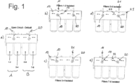
- Fig. 1 shows an embodiment of a filtration system of the present invention.
- the filtration system comprises two groups A and B of filters arranged in parallel in a fluid pathway of the filtration system.
- Each group comprises at least a first filter 1-2, 5-6 and a second filter 2-3, 7-8.
- duplex filters are used.
- Each duplex filter comprises two filters or filter elements arranged and operated in parallel.
- the first group A therefore comprises the first filter elements 1-2 forming a first duplex filter, and the second filters 3-4 forming a second duplex filter.
- the second group B comprises the first filters 5-6 forming a first duplex filter and the second filters 7-8 forming a second duplex filter.
- the present invention could also be use single filters or filters having more than two filters arranged and operated in parallel.
- Each group of filters A, B comprises an operating element 10, 20 for selectively isolating either the first or the second filters from the filtration system. In a default position of the operating element, both the first and second filters are connected to the filtration system.
- the filter cartridge of the filter can be exchanged.
- the filtration system can be operated using the filters which are still connected.
- Each of the operating elements is configured such that it only isolates, in each isolating position, either the first or the second filters from the filtration system, while the remaining second or first filters are still connected to the filtration system. This principle allows replacing a filter cartridge while the filtration system is working, because for each group of filters, at least one out of the first and the second filters will be connected to the filtration system and therefore working.
- the filtration system of the present invention therefore comprises a mechanical blocking mechanism that will avoid such a situation, because moving the one operating element out of its default position will actuate the blocking mechanism to block the other operating element in its default position.
- Fig. 1 shows the five possible switching positions of the operating elements 10 and 20.
- both operating elements 10, 20 are in their default position, such that all filters are connected to the filtration system.
- the first operating element 10 is in its first isolating position 13, isolating the first filters 1-2.
- the first operating element 10 is in its second isolating position 12, isolating the second filters 3-4.
- the second operating element 20 is in its first isolating position 23, isolating the first filters 5-6.
- the second operating element 20 is in its second isolating position 22, isolating the second filters 7-8.
- the second operating element 20 is in its default position 21, while in situations d) and e), the first operating element 10 is in its default position 11. Situations where both operating elements are in an isolating position are avoided by the mechanical blocking mechanism.
- Fig. 2 shows some of the main components of an embodiment of the mechanical blocking mechanism. These components of the mechanical blocking mechanism also shown in fig. 3 separately for groups A and B.
- the mechanical blocking mechanism comprises a first blocking element 30 operated by the first operating element 10 to block the second operating element 20, and a second blocking element 40 operated by the second operating element 20 to block the first operating element 10.
- the blocking elements 30, 40 are respectively operated by a driving element 14, 24, fixedly connected to the respective operating element 10, 20.
- Each driving element 14, 24 comprises a guide 15, 25 cooperating with a respective pin 31, 41 connected to the respective blocking element 30, 40.
- the operating elements each have an axis of rotation 18, 28, and can be rotated from the default position 11, 21 to the two isolating positions 12, 13 and 22, 23 respectively.
- the isolating positions are arranged on opposite sides of the default position.
- each operating element 10, 20 operates, by this rotation, a valve element 16, 26 to either open fluid passages or close fluid passages in a valve.
- the valve element 16 is integrated into the axis of each operating element.
- Section 17, 27 separates an inlet passage of the valve from an outlet passage of the valve, which are both closed and opened by each valve element 16, 26.
- the corresponding drive element 14, 24 will equally rotate, such that the guide will be displaced in a rotational movement. Because the distance of the guide 15, 25 to the axis of the respective operating element varies along the extension of the guide, the respective pin 31, 41 slidably engaged within the respective guide 15, 25 will be displaced by such a rotation.
- both blocking elements 30, 40 are linearly movable from a default position to a blocking position.
- guide pins 51 engage with long holes 33, 43 of the blocking elements to allow a sliding movement of each blocking element along a linear path.
- the guide pins 31, 41 connected to the blocking elements 30, 40 will displace the blocking elements, depending on the position of the drive element 14, 24, along this linear direction.
- the blocking elements are arranged to extend from the respective drive element that will operate the blocking element to a counter element of the other operating element to engage with the counter element in their blocking position.
- the blocking elements are plate elements or bars extending between the two operating elements.
- the two blocking elements are placed on top of each other, with the same guiding pins 51 reaching through guide holes 33, 43 in both blocking elements.
- the blocking elements are arranged to extend along a line connecting the two axes 18, 28 of the two operating elements, 10, 20.
- At least one of the blocking elements 30, 40 has a slot 42 arranged in the end section opposite the pin 41, in order to allow the pin 31 of the other blocking element to extend through the blocking element 40 in order to engage with the respective drive element 14.
- each guide 15, 25 has a first guide section 15', 25' in which the respective pin 31, 41 is arranged if the operating element in in its default position. Further, second guide sections 15", 25" extend on both sides of the first guide section 15', 25'. Once the operating element is moved from its default position in the directions of one of its isolating positions, the pin 31, 41 will move from the first guide section 15', 25' into one of the second guide sections 15", 25".
- the second guide sections 15", 25" are arcuate sections extending at a radius with respect to the axis of the respective operating element which is larger than the distance of the first guide sections 15', 25' to the respective axis.
- Fig. 4b shows the valve elements 16 in the respective default positions opening flow channels to the respective filters.
- Each operating element 10, 18 has a handle 18, 28 for rotating the operating element.
- the handle is a lever.
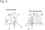
- Fig. 5 shows the two possible configurations between a blocking element and its respective counter element.
- the ends of the blocking elements 30, 40 opposite the respective pins 31, 41 have blocking edges 34, 44 that can be engaged with a recess 61, 71 of the respective counter element 60, 70.
- the recess 61, 71 therefore forms a blocking section engaging with the blocking element.
- Fig. 5 shows on the left hand side a situation where group A, i.e. the first operating element 10, is free to rotate because the second blocking element 40 comprising the blocking edges 44 is not engaged with the recess 61 of the counter element 60, with a distance d remaining between the sides 62 of the recess 61 and the blocking edges 44.
- group B i.e. the second operating element 20
- the blocking edges 34 of the first blocking element 30 are engaged into the recess 71, with an interference e between the blocking edges 34 and the sides 72 of the recess 70 blocking a rotational movement.
- the sides 62, 72 of the recesses 61, 71 therefore form counter-blocking edges cooperating with the blocking edges of the blocking elements.
- the respective counter elements 60, 70 are fixedly attached to the respective operating elements 10, 20 to block the rotational movement of the respective operating element 10, 20 when engaged with the blocking element.
- FIG. 6 to 8 now shows different switching positions of the filtration system and the respective positions of the blocking elements and their counter elements.
- Fig. 6 shows situation a) of Fig. 1 , i.e. where both operating elements are in their default position. Therefore, the pins 31 and 41 are arranged in the respective default sections 15', 25' of the guides such that the blocking element are in their default positions, with the blocking edges 34, 44 arranged with a distance d to the sides 62, 72 of the recesses 61, 71, such that both operating elements are free to rotate.
- Fig. 7 shows situation b) of Fig. 1 , with the first operating element in its first isolation position isolating the first filters 1 - 2.
- pin 31 of the first blocking element 30 is in the isolating section 15" of the guide 15, moving the blocking element 30 in the direction of the second operating element 20.
- the blocking edges 34 engage into the recess 71, with an interference e between the blocking edges 34 of the blocking element 30 and the sides 72 of the recess 71 blocking rotation of the counter element 70.
- group B and therefore the second operating element is blocked from rotating.
- Fig. 8 shows the corresponding situation for group A or the first operating element 10 being blocked by the second operating 20 being in the first isolating position, corresponding to situation d) of Fig. 1 .
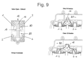
- valve element 16 is shown in Fig. 9 for the first operating element 10 or group A.
- the configuration of the second operating element 20 and group B is the same.
- the valve has two sections, one for the inlets to the filters, one or the outlets.
- the sections for the inlets correspond to the dirty oil section 80, the sections for the outlets to the clean oil sections 90 shown in fig. 9 .
- the two sections are arranged next to each other along the axial direction of the valve element, and separated by a separating block 17.
- the valve element 16 will open a respective flow path from a fluid duct 80, 90 of the filtration system to the corresponding inlets or outlets of all the filters associated to the respective valve.
- a rotation in the second direction will block the inlets and outlets of the second filters while leaving the inlets and outlets of the first filters connected.
- the filters 1 - 2 of the first duplex filter are connected in parallel both on the outlet and on the inlet side to the valve.
- the same is true for the filters 3 - 4 of the second duplex filter.
- single filters could equally be used.
- each filter has a filter head housing 90 comprising the connections to the respective valve, and a filter cartridge housing 91 connected to the filter head housing 90.
- the filter cartridge housing 91 can be removed, the filter cartridge replaced and the filter cartridge housing installed again.
- the filtration system of the present invention can for example be used for internal combustion engines, in particular as a filtration system of the lubricating system.
- the filtration system can also be used in any other application where a number of filters are operating in parallel in a fluid duct.
Landscapes
- Chemical & Material Sciences (AREA)
- Engineering & Computer Science (AREA)
- Chemical Kinetics & Catalysis (AREA)
- Combustion & Propulsion (AREA)
- Mechanical Engineering (AREA)
- General Engineering & Computer Science (AREA)
- Lubrication Details And Ventilation Of Internal Combustion Engines (AREA)
- Filtration Of Liquid (AREA)
Claims (14)
- Filtersystem, aufweisendeine Vielzahl von Filtern (1-2, 3-4, 5-6, 7-8), insbesondere Öl- oder Kraftstofffi lter,ein erstes Betätigungselement (10), das von einer Standardposition (11) in zumindest eine Isolationsposition (12, 13) bewegbar ist, um zumindest einen Filter (1-2, 3-4) einer ersten Gruppe (A) von Filtern von dem Filtersystem zu isolieren,ein zweites Betätigungselement (20), das von einer Standardposition (21) in zumindest eine Isolationsposition (22, 23) bewegbar ist, um zumindest einen Filter (5-6, 7-8) einer zweiten Gruppe (B) von Filtern von dem Filtersystem zu isolieren, undeinen mechanischen Sperrmechanismus, der durch eine Bewegung des ersten Betätigungselements (10) aus seiner Standardposition (11) heraus betätigt wird, um das zweite Betätigungselement (20) in seiner Standardposition (21) zu sperren, und der durch eine Bewegung des zweiten Betätigungselements (20) aus seiner Standardposition (21) heraus betätigt wird, um das erste Betätigungselement (10) in seiner Standardposition (11) zu sperren,wobei in der Standardposition (11, 21) des ersten und des zweiten Betätigungselements (10, 20) alle Filter der jeweiligen Gruppe von Filtern (A, B) mit dem Filtersystem verbunden sind,dadurch gekennzeichnet, dassjedem Betätigungselement (10, 20) zumindest zwei Filter zugeordnet sind, wobei das Betätigungselement (10, 20) derart konfiguriert ist, dass es selektiv zumindest einen ersten Filter (1-2, 5-6) unter den zumindest zwei Filtern von dem Filtersystem in einer ersten Isolationsposition (13, 23) und zumindest einen zweiten Filter (3-4, 7-8) unter den zumindest zwei Filtern in einer zweiten Isolationsposition (12, 22) isoliert.
- Filtersystem nach Anspruch 1, wobei jeder Filter (1-2, 3-4, 5-6, 7-8) zumindest ein Duplexfilter ist, der zwei parallel angeordnete Filter oder Filterelemente aufweist.
- Filtersystem nach einem der vorstehenden Ansprüche, wobei alle Filter (1-2, 3-4, 5-6, 7-8) parallel in einer Fluidleitung des Filtersystems angeordnet sind.
- Filtersystem nach einem der vorstehenden Ansprüche, wobei der mechanische Sperrmechanismus ein erstes Sperrelement (30), das von dem ersten Betätigungselement (10) zum Sperren des zweiten Betätigungselements (20) betätigt wird, und ein zweites Sperrelement (40), das von dem zweiten Betätigungselement (20) zum Sperren des ersten Betätigungselements (10) betätigt wird, aufweist.
- Filtersystem nach Anspruch 4, wobei die Sperrelemente (30, 40) verschiebbar auf dem Filtersystem angeordnet sind, um von einer Standardposition in eine Sperrposition bewegt zu werden.
- Filtersystem nach Anspruch 4 oder 5, wobei das erste Blockierelement (30) und das zweite Blockierelement (40) übereinander angeordnet sind und bevorzugt durch einen oder mehrere Führungsstifte (51) geführt werden, die sich durch lineare Schlitze (33, 43) in den Blockierelementen erstrecken.
- Filtersystem nach einem der Ansprüche 4 bis 6, wobei das erste Sperrelement (30) mit einem Antriebselement (14) des ersten Betätigungselements (10) wirkverbunden ist und das zweite Sperrelement (40) mit einem Antriebselement (24) des zweiten Betätigungselements (20) wirkverbunden ist, wobei die Sperrelemente (30, 40) bevorzugt in einem der Endabschnitte der jeweiligen Blockierelemente mit dem jeweiligen Antriebselement (14, 24) wirkverbunden sind und/oder die Antriebselemente (14, 24) bevorzugt jeweils eine Führung (15, 25) aufweisen, die mit einem Stift (31, 41) des jeweiligen Blockierelements zusammenwirkt, wobei die Führung bevorzugt in Form eines Schlitzes konfiguriert ist.
- Filtersystem nach einem der vorstehenden Ansprüche, wobei die Betätigungselemente (10, 20) von der Standardposition (11, 21) in die Isolationspositionen (12, 13, 22, 23) drehbar sind, wobei die Betätigungselemente (10, 20) bevorzugt von der Standardposition in zwei entgegengesetzten Richtungen in den jeweiligen Isolationspositionen (12, 13, 22, 23) drehbar sind.
- Filtersystem nach Anspruch 8, wobei ein Antriebselement (14, 24) zum Antreiben eines Sperrelements (30, 40) durch die Drehung des Betätigungselements (10, 20) gedreht wird, wobei sich eine Führung (15, 25) des Antriebselements bevorzugt in einem ersten radialen Abstand von einer Drehachse des Antriebselements (14, 24) in einem Standardabschnitt befindet und von dem Standardabschnitt zu einem bogenförmigen Abschnitt verläuft, wo sie in einem zweiten radialen Abstand von der Drehachse des Antriebselements verläuft, wobei ein Stift (31, 41) des Sperrelements (30, 40) bevorzugt in dem Standardabschnitt der Führung (15, 25) angeordnet ist, wenn sich das Betätigungselement in der Standardposition (11, 21) befindet, und sich von dem Standardabschnitt zu dem gebogenen Abschnitt bewegt, sobald das Betätigungselement aus der Standardposition (11, 21) in eine Isolationsposition (12, 13, 22, 23) gedreht wird, so dass das Blockierelement (30, 40) durch den Unterschied hinsichtlich des Radius der Führung in dem Standardabschnitt zu dem gebogenen Abschnitt verlagert wird, wobei die Führung (15, 25) bevorzugt gebogene Abschnitte auf beiden Seiten des Standardabschnitts aufweist, die den beiden Isolationspositionen entsprechen.
- Filtersystem nach Anspruch 8 oder 9, wobei die Betätigungselemente (10, 20) ein Ventilelement (16, 26) aufweisen und/oder steuern, das in einem Ventilkörper gedreht wird, um zumindest eine Fluidverbindung durch einen Fluidkanal des Ventilelements (16, 26) in der Standardposition herzustellen und die Fluidverbindung in der Isolationsposition zu blockieren, wobei das Ventilelement (16, 26) bevorzugt eine erste und eine zweite Fluidverbindung mit einem Einlassanschluss und einem Auslassanschluss jedes dem Betätigungselement (10, 20) zugeordneten Filters in der Standardposition herstellt und die erste und die zweite Fluidverbindung mit zumindest einem Filter in einer Isolationsposition blockiert.
- Filtersystem nach einem der vorstehenden Ansprüche, wobei ein erstes Sperrelement (30) einen Sperrabschnitt (34) aufweist, der in Sperreingriff mit einem Sperrabschnitt (62) des ersten Betätigungselements bewegbar ist, und ein zweites Sperrelement (40) einen Sperrabschnitt (44) aufweist, der in Sperreingriff mit einem Sperrabschnitt (72) des zweiten Betätigungselements bewegbar ist.
- Filtersystem nach Anspruch 11, wobei die Blockierabschnitte (34, 44) der Blockierelemente durch jeweilige Endabschnitte der Blockierelemente gebildet werden und/oder die Blockierabschnitte (62, 72) der Betätigungselemente durch jeweilige Ausnehmungen gebildet werden und/oder die Blockierabschnitte Drehbewegung des jeweiligen Betätigungselements blockieren, wenn sie miteinander in Eingriff stehen.
- Filtersystem nach einem der vorstehenden Ansprüche, wobei jeder Filter oder jedes Filterelement zumindest ein Filterkopfgehäuse und eine austauschbare Filterpatrone aufweist.
- Maschine, welche eine Fluidleitung und ein Filtersystem nach einem der vorstehenden Ansprüche aufweist, das in der Fluidleitung angeordnet ist, wobei die Maschine bevorzugt ein Motor ist und/oder die Fluidleitung eine Öl- oder Kraftstoffleitung ist.
Applications Claiming Priority (1)
| Application Number | Priority Date | Filing Date | Title |
|---|---|---|---|
| DE102021125041 | 2021-09-28 |
Publications (2)
| Publication Number | Publication Date |
|---|---|
| EP4154963A1 EP4154963A1 (de) | 2023-03-29 |
| EP4154963B1 true EP4154963B1 (de) | 2024-11-20 |
Family
ID=83151592
Family Applications (1)
| Application Number | Title | Priority Date | Filing Date |
|---|---|---|---|
| EP22193398.9A Active EP4154963B1 (de) | 2021-09-28 | 2022-09-01 | Filtrierungssystem |
Country Status (2)
| Country | Link |
|---|---|
| US (1) | US12241440B2 (de) |
| EP (1) | EP4154963B1 (de) |
Families Citing this family (1)
| Publication number | Priority date | Publication date | Assignee | Title |
|---|---|---|---|---|
| US11946439B2 (en) * | 2022-05-09 | 2024-04-02 | Caterpillar Inc. | Fuel module for engine having service valve assembly for common drain from primary and secondary filters |
Family Cites Families (7)
| Publication number | Priority date | Publication date | Assignee | Title |
|---|---|---|---|---|
| DE112510C (de) * | 1899-04-16 | 1900-08-10 | ||
| US2505375A (en) * | 1948-12-28 | 1950-04-25 | Bethlehem Steel Corp | Duplex fluid strainer |
| DE19851193C1 (de) | 1998-11-06 | 2000-04-13 | Hydac Filtertechnik Gmbh | Filteranordnung mit mindestens zwei Filterkammern |
| NL1013330C2 (nl) | 1999-10-18 | 2001-04-19 | Indufil B V | Schakelinrichting en mediumstroom naar keuze door een eerste of tweede behandelorgaan te leiden. |
| CA2707230A1 (en) | 2009-06-11 | 2010-12-11 | Thomas Rahm | Filter switching apparatus |
| US10926205B2 (en) * | 2017-06-20 | 2021-02-23 | Eaton Intelligent Power Limited | Cast filter assembly-modular design |
| CN111085033B (zh) * | 2019-12-29 | 2022-05-17 | 西安昊池环保工程有限公司 | 基于超压导通阀门的并联式润滑油精滤方法 |
-
2022
- 2022-09-01 EP EP22193398.9A patent/EP4154963B1/de active Active
- 2022-09-21 US US17/934,130 patent/US12241440B2/en active Active
Also Published As
| Publication number | Publication date |
|---|---|
| US20230123929A1 (en) | 2023-04-20 |
| EP4154963A1 (de) | 2023-03-29 |
| US12241440B2 (en) | 2025-03-04 |
Similar Documents
| Publication | Publication Date | Title |
|---|---|---|
| EP4154963B1 (de) | Filtrierungssystem | |
| EP2696118B1 (de) | Impulstastverhältnisventile | |
| DE19637174C2 (de) | Schaltventil | |
| EP1596104A2 (de) | Vorrichtung zum Ansteuern einer Mehrzahl von hydraulischen Schaltzylindern sowie Hydraulikversorgungssystem für ein Doppelkupplungsgetriebe | |
| EP2971894A1 (de) | Transflussventil mit einem isolier- und schaltmechanismus für doppelte blockierungs- und auslassanordnung | |
| DE69814539T2 (de) | Magnetventil mit drei Anschlüssen im Gehäuse eines Magnetventils mit fünf Anschlüssen | |
| DE102005019516A1 (de) | Vorrichtung zum Ansteuern einer Mehrzahl von hydraulischen Schaltzylindern sowie Hydraulikversorgungssystem für ein Doppelkupplungsgetriebe | |
| EP2378127B1 (de) | Strömungsführendes Bauteil mit Pumpe und Armatur | |
| GB2033546A (en) | Multi-valve interlock apparatus and method of manufacture | |
| EP0993574A4 (de) | Mehrwegventil und verfahren | |
| SE465637B (sv) | Styrda reglerventiler foer kylmedel | |
| KR102812080B1 (ko) | 개선된 커버 조립체를 갖는 여과 유닛 | |
| RU2559654C2 (ru) | Переключающее устройство для подачи текучей среды | |
| DE4027610C2 (de) | Ventil | |
| DE102019220442A1 (de) | Pumpeneinheit | |
| EP3368772B1 (de) | Herausziehbare ventilgruppe mit obturatorgruppe mit mehreren aktiven teilen | |
| US4047540A (en) | Multi-path valve structure having extended life and backwashing capability | |
| US5855226A (en) | Valve actuator | |
| EP2080455A1 (de) | Mehrwege-Absperrvorrichtung für Flüssigkeiten, insbesondere zur Anwendung an Getränkeautomaten | |
| DE10209335A1 (de) | Ventileinrichtung | |
| DE102012010681A1 (de) | Anordnung zur Temperierung des Schmiermittels einer Brennkraftmaschine | |
| EP3901501A1 (de) | Servoventil | |
| DE102013104869A1 (de) | Kraft- und Arbeitsmaschine mit Rotationskolben | |
| DE102014011746B4 (de) | Kühlmittelkreislauf für ein Fahrzeug sowie Drehsteller für einen solchen Kühlmittelkreislauf | |
| DE112023000568T5 (de) | Planetenfluidsteuerventil |
Legal Events
| Date | Code | Title | Description |
|---|---|---|---|
| PUAI | Public reference made under article 153(3) epc to a published international application that has entered the european phase |
Free format text: ORIGINAL CODE: 0009012 |
|
| STAA | Information on the status of an ep patent application or granted ep patent |
Free format text: STATUS: THE APPLICATION HAS BEEN PUBLISHED |
|
| AK | Designated contracting states |
Kind code of ref document: A1 Designated state(s): AL AT BE BG CH CY CZ DE DK EE ES FI FR GB GR HR HU IE IS IT LI LT LU LV MC MK MT NL NO PL PT RO RS SE SI SK SM TR |
|
| STAA | Information on the status of an ep patent application or granted ep patent |
Free format text: STATUS: REQUEST FOR EXAMINATION WAS MADE |
|
| 17P | Request for examination filed |
Effective date: 20230928 |
|
| GRAP | Despatch of communication of intention to grant a patent |
Free format text: ORIGINAL CODE: EPIDOSNIGR1 |
|
| STAA | Information on the status of an ep patent application or granted ep patent |
Free format text: STATUS: GRANT OF PATENT IS INTENDED |
|
| INTG | Intention to grant announced |
Effective date: 20240708 |
|
| GRAS | Grant fee paid |
Free format text: ORIGINAL CODE: EPIDOSNIGR3 |
|
| GRAA | (expected) grant |
Free format text: ORIGINAL CODE: 0009210 |
|
| STAA | Information on the status of an ep patent application or granted ep patent |
Free format text: STATUS: THE PATENT HAS BEEN GRANTED |
|
| AK | Designated contracting states |
Kind code of ref document: B1 Designated state(s): AL AT BE BG CH CY CZ DE DK EE ES FI FR GB GR HR HU IE IS IT LI LT LU LV MC MK MT NL NO PL PT RO RS SE SI SK SM TR |
|
| RAP3 | Party data changed (applicant data changed or rights of an application transferred) |
Owner name: LIEBHERR-COMPONENTS COLMAR SAS |
|
| REG | Reference to a national code |
Ref country code: GB Ref legal event code: FG4D |
|
| REG | Reference to a national code |
Ref country code: CH Ref legal event code: EP |
|
| REG | Reference to a national code |
Ref country code: DE Ref legal event code: R096 Ref document number: 602022007868 Country of ref document: DE |
|
| REG | Reference to a national code |
Ref country code: IE Ref legal event code: FG4D |
|
| REG | Reference to a national code |
Ref country code: AT Ref legal event code: UEP Ref document number: 1743080 Country of ref document: AT Kind code of ref document: T Effective date: 20241120 |
|
| REG | Reference to a national code |
Ref country code: LT Ref legal event code: MG9D |
|
| REG | Reference to a national code |
Ref country code: NL Ref legal event code: MP Effective date: 20241120 |
|
| PG25 | Lapsed in a contracting state [announced via postgrant information from national office to epo] |
Ref country code: HR Free format text: LAPSE BECAUSE OF FAILURE TO SUBMIT A TRANSLATION OF THE DESCRIPTION OR TO PAY THE FEE WITHIN THE PRESCRIBED TIME-LIMIT Effective date: 20241120 Ref country code: IS Free format text: LAPSE BECAUSE OF FAILURE TO SUBMIT A TRANSLATION OF THE DESCRIPTION OR TO PAY THE FEE WITHIN THE PRESCRIBED TIME-LIMIT Effective date: 20250320 Ref country code: PT Free format text: LAPSE BECAUSE OF FAILURE TO SUBMIT A TRANSLATION OF THE DESCRIPTION OR TO PAY THE FEE WITHIN THE PRESCRIBED TIME-LIMIT Effective date: 20250320 |
|
| PG25 | Lapsed in a contracting state [announced via postgrant information from national office to epo] |
Ref country code: NL Free format text: LAPSE BECAUSE OF FAILURE TO SUBMIT A TRANSLATION OF THE DESCRIPTION OR TO PAY THE FEE WITHIN THE PRESCRIBED TIME-LIMIT Effective date: 20241120 Ref country code: FI Free format text: LAPSE BECAUSE OF FAILURE TO SUBMIT A TRANSLATION OF THE DESCRIPTION OR TO PAY THE FEE WITHIN THE PRESCRIBED TIME-LIMIT Effective date: 20241120 |
|
| PG25 | Lapsed in a contracting state [announced via postgrant information from national office to epo] |
Ref country code: BG Free format text: LAPSE BECAUSE OF FAILURE TO SUBMIT A TRANSLATION OF THE DESCRIPTION OR TO PAY THE FEE WITHIN THE PRESCRIBED TIME-LIMIT Effective date: 20241120 |
|
| PG25 | Lapsed in a contracting state [announced via postgrant information from national office to epo] |
Ref country code: ES Free format text: LAPSE BECAUSE OF FAILURE TO SUBMIT A TRANSLATION OF THE DESCRIPTION OR TO PAY THE FEE WITHIN THE PRESCRIBED TIME-LIMIT Effective date: 20241120 |
|
| PG25 | Lapsed in a contracting state [announced via postgrant information from national office to epo] |
Ref country code: NO Free format text: LAPSE BECAUSE OF FAILURE TO SUBMIT A TRANSLATION OF THE DESCRIPTION OR TO PAY THE FEE WITHIN THE PRESCRIBED TIME-LIMIT Effective date: 20250220 |
|
| PG25 | Lapsed in a contracting state [announced via postgrant information from national office to epo] |
Ref country code: LV Free format text: LAPSE BECAUSE OF FAILURE TO SUBMIT A TRANSLATION OF THE DESCRIPTION OR TO PAY THE FEE WITHIN THE PRESCRIBED TIME-LIMIT Effective date: 20241120 Ref country code: GR Free format text: LAPSE BECAUSE OF FAILURE TO SUBMIT A TRANSLATION OF THE DESCRIPTION OR TO PAY THE FEE WITHIN THE PRESCRIBED TIME-LIMIT Effective date: 20250221 |
|
| PG25 | Lapsed in a contracting state [announced via postgrant information from national office to epo] |
Ref country code: PL Free format text: LAPSE BECAUSE OF FAILURE TO SUBMIT A TRANSLATION OF THE DESCRIPTION OR TO PAY THE FEE WITHIN THE PRESCRIBED TIME-LIMIT Effective date: 20241120 |
|
| PG25 | Lapsed in a contracting state [announced via postgrant information from national office to epo] |
Ref country code: RS Free format text: LAPSE BECAUSE OF FAILURE TO SUBMIT A TRANSLATION OF THE DESCRIPTION OR TO PAY THE FEE WITHIN THE PRESCRIBED TIME-LIMIT Effective date: 20250220 |
|
| PG25 | Lapsed in a contracting state [announced via postgrant information from national office to epo] |
Ref country code: SM Free format text: LAPSE BECAUSE OF FAILURE TO SUBMIT A TRANSLATION OF THE DESCRIPTION OR TO PAY THE FEE WITHIN THE PRESCRIBED TIME-LIMIT Effective date: 20241120 |
|
| PG25 | Lapsed in a contracting state [announced via postgrant information from national office to epo] |
Ref country code: DK Free format text: LAPSE BECAUSE OF FAILURE TO SUBMIT A TRANSLATION OF THE DESCRIPTION OR TO PAY THE FEE WITHIN THE PRESCRIBED TIME-LIMIT Effective date: 20241120 |
|
| PG25 | Lapsed in a contracting state [announced via postgrant information from national office to epo] |
Ref country code: EE Free format text: LAPSE BECAUSE OF FAILURE TO SUBMIT A TRANSLATION OF THE DESCRIPTION OR TO PAY THE FEE WITHIN THE PRESCRIBED TIME-LIMIT Effective date: 20241120 |
|
| PG25 | Lapsed in a contracting state [announced via postgrant information from national office to epo] |
Ref country code: RO Free format text: LAPSE BECAUSE OF FAILURE TO SUBMIT A TRANSLATION OF THE DESCRIPTION OR TO PAY THE FEE WITHIN THE PRESCRIBED TIME-LIMIT Effective date: 20241120 |
|
| PG25 | Lapsed in a contracting state [announced via postgrant information from national office to epo] |
Ref country code: SK Free format text: LAPSE BECAUSE OF FAILURE TO SUBMIT A TRANSLATION OF THE DESCRIPTION OR TO PAY THE FEE WITHIN THE PRESCRIBED TIME-LIMIT Effective date: 20241120 |
|
| PG25 | Lapsed in a contracting state [announced via postgrant information from national office to epo] |
Ref country code: CZ Free format text: LAPSE BECAUSE OF FAILURE TO SUBMIT A TRANSLATION OF THE DESCRIPTION OR TO PAY THE FEE WITHIN THE PRESCRIBED TIME-LIMIT Effective date: 20241120 |
|
| REG | Reference to a national code |
Ref country code: DE Ref legal event code: R097 Ref document number: 602022007868 Country of ref document: DE |
|
| PG25 | Lapsed in a contracting state [announced via postgrant information from national office to epo] |
Ref country code: SE Free format text: LAPSE BECAUSE OF FAILURE TO SUBMIT A TRANSLATION OF THE DESCRIPTION OR TO PAY THE FEE WITHIN THE PRESCRIBED TIME-LIMIT Effective date: 20241120 |
|
| PLBE | No opposition filed within time limit |
Free format text: ORIGINAL CODE: 0009261 |
|
| STAA | Information on the status of an ep patent application or granted ep patent |
Free format text: STATUS: NO OPPOSITION FILED WITHIN TIME LIMIT |
|
| REG | Reference to a national code |
Ref country code: CH Ref legal event code: U11 Free format text: ST27 STATUS EVENT CODE: U-0-0-U10-U11 (AS PROVIDED BY THE NATIONAL OFFICE) Effective date: 20251001 |
|
| PGFP | Annual fee paid to national office [announced via postgrant information from national office to epo] |
Ref country code: FR Payment date: 20250926 Year of fee payment: 4 Ref country code: AT Payment date: 20251020 Year of fee payment: 4 |
|
| 26N | No opposition filed |
Effective date: 20250821 |
|
| PGFP | Annual fee paid to national office [announced via postgrant information from national office to epo] |
Ref country code: DE Payment date: 20251002 Year of fee payment: 4 |
|
| PGFP | Annual fee paid to national office [announced via postgrant information from national office to epo] |
Ref country code: IT Payment date: 20250930 Year of fee payment: 4 |
|
| PGFP | Annual fee paid to national office [announced via postgrant information from national office to epo] |
Ref country code: CH Payment date: 20251001 Year of fee payment: 4 |