EP4155105A1 - Essieu électrique - Google Patents
Essieu électrique Download PDFInfo
- Publication number
- EP4155105A1 EP4155105A1 EP21199482.7A EP21199482A EP4155105A1 EP 4155105 A1 EP4155105 A1 EP 4155105A1 EP 21199482 A EP21199482 A EP 21199482A EP 4155105 A1 EP4155105 A1 EP 4155105A1
- Authority
- EP
- European Patent Office
- Prior art keywords
- rotor
- commercial vehicle
- electrically driven
- driven axle
- electric
- Prior art date
- Legal status (The legal status is an assumption and is not a legal conclusion. Google has not performed a legal analysis and makes no representation as to the accuracy of the status listed.)
- Pending
Links
Images


Classifications
-
- B—PERFORMING OPERATIONS; TRANSPORTING
- B60—VEHICLES IN GENERAL
- B60K—ARRANGEMENT OR MOUNTING OF PROPULSION UNITS OR OF TRANSMISSIONS IN VEHICLES; ARRANGEMENT OR MOUNTING OF PLURAL DIVERSE PRIME-MOVERS IN VEHICLES; AUXILIARY DRIVES FOR VEHICLES; INSTRUMENTATION OR DASHBOARDS FOR VEHICLES; ARRANGEMENTS IN CONNECTION WITH COOLING, AIR INTAKE, GAS EXHAUST OR FUEL SUPPLY OF PROPULSION UNITS IN VEHICLES
- B60K7/00—Disposition of motor in, or adjacent to, traction wheel
- B60K7/0007—Disposition of motor in, or adjacent to, traction wheel the motor being electric
-
- B—PERFORMING OPERATIONS; TRANSPORTING
- B60—VEHICLES IN GENERAL
- B60K—ARRANGEMENT OR MOUNTING OF PROPULSION UNITS OR OF TRANSMISSIONS IN VEHICLES; ARRANGEMENT OR MOUNTING OF PLURAL DIVERSE PRIME-MOVERS IN VEHICLES; AUXILIARY DRIVES FOR VEHICLES; INSTRUMENTATION OR DASHBOARDS FOR VEHICLES; ARRANGEMENTS IN CONNECTION WITH COOLING, AIR INTAKE, GAS EXHAUST OR FUEL SUPPLY OF PROPULSION UNITS IN VEHICLES
- B60K17/00—Arrangement or mounting of transmissions in vehicles
- B60K17/04—Arrangement or mounting of transmissions in vehicles characterised by arrangement, location or kind of gearing
- B60K17/043—Transmission unit disposed in on near the vehicle wheel, or between the differential gear unit and the wheel
-
- H—ELECTRICITY
- H02—GENERATION; CONVERSION OR DISTRIBUTION OF ELECTRIC POWER
- H02K—DYNAMO-ELECTRIC MACHINES
- H02K7/00—Arrangements for handling mechanical energy structurally associated with dynamo-electric machines, e.g. structural association with mechanical driving motors or auxiliary dynamo-electric machines
- H02K7/08—Structural association with bearings
-
- B—PERFORMING OPERATIONS; TRANSPORTING
- B60—VEHICLES IN GENERAL
- B60K—ARRANGEMENT OR MOUNTING OF PROPULSION UNITS OR OF TRANSMISSIONS IN VEHICLES; ARRANGEMENT OR MOUNTING OF PLURAL DIVERSE PRIME-MOVERS IN VEHICLES; AUXILIARY DRIVES FOR VEHICLES; INSTRUMENTATION OR DASHBOARDS FOR VEHICLES; ARRANGEMENTS IN CONNECTION WITH COOLING, AIR INTAKE, GAS EXHAUST OR FUEL SUPPLY OF PROPULSION UNITS IN VEHICLES
- B60K7/00—Disposition of motor in, or adjacent to, traction wheel
- B60K2007/0038—Disposition of motor in, or adjacent to, traction wheel the motor moving together with the wheel axle
-
- B—PERFORMING OPERATIONS; TRANSPORTING
- B60—VEHICLES IN GENERAL
- B60K—ARRANGEMENT OR MOUNTING OF PROPULSION UNITS OR OF TRANSMISSIONS IN VEHICLES; ARRANGEMENT OR MOUNTING OF PLURAL DIVERSE PRIME-MOVERS IN VEHICLES; AUXILIARY DRIVES FOR VEHICLES; INSTRUMENTATION OR DASHBOARDS FOR VEHICLES; ARRANGEMENTS IN CONNECTION WITH COOLING, AIR INTAKE, GAS EXHAUST OR FUEL SUPPLY OF PROPULSION UNITS IN VEHICLES
- B60K7/00—Disposition of motor in, or adjacent to, traction wheel
- B60K2007/0061—Disposition of motor in, or adjacent to, traction wheel the motor axle being parallel to the wheel axle
-
- B—PERFORMING OPERATIONS; TRANSPORTING
- B60—VEHICLES IN GENERAL
- B60Y—INDEXING SCHEME RELATING TO ASPECTS CROSS-CUTTING VEHICLE TECHNOLOGY
- B60Y2200/00—Type of vehicle
- B60Y2200/10—Road Vehicles
- B60Y2200/14—Trucks; Load vehicles, Busses
-
- B—PERFORMING OPERATIONS; TRANSPORTING
- B60—VEHICLES IN GENERAL
- B60Y—INDEXING SCHEME RELATING TO ASPECTS CROSS-CUTTING VEHICLE TECHNOLOGY
- B60Y2410/00—Constructional features of vehicle sub-units
- B60Y2410/102—Shaft arrangements; Shaft supports, e.g. bearings
Definitions
- the invention relates to an electrically driven axle for commercial vehicles, which is driven by means of two electric motors, each assigned to the drive wheels, and the associated gearbox.
- Wheel bearings, transmission bearings and dynamo-electric machines each have their own storage with their necessary degrees of freedom.
- the dynamoelectric machine is usually connected on the rotor side via a clutch to a transmission input shaft and on the stator side to an axle housing.
- the additional radial and axial bearing points of the dynamoelectric machine represent a mechanical overdetermination of the drive axle, so that the coupling between the wheel and motor shaft or rotor shaft must be designed to be flexible.
- the invention is based on the object of providing an electric axis which has a simple, compact structure and avoids the disadvantages mentioned above. Furthermore, a commercial vehicle is to be provided which, among other things, is designed to be space-optimized.
- the dynamo-electric rotary machines are designed without bearings, ie overhung, so that the bearing of the transmission also takes over the rotating active part components of the electric machine.
- the active part components are the laminated core of the rotor, in which permanent magnets and/or an electrically conductive cage are embedded.
- the bearing of a transmission input shaft is to be designed in such a way that the additionally introduced mechanical loads of the rotor of the dynamoelectric machine are also absorbed. Furthermore, it is particularly advantageous if the additional weight and moment of inertia of the rotor are as small as possible.
- the active parts of the rotor are positioned on a weight-optimized rotor hub, which transmits the torque to the shaft without itself having a large moment of inertia and large masses.
- the rotor of the dynamoelectric machine is attached directly to the transmission input shaft in a rotationally fixed manner, with the stator of the dynamoelectric machine being mechanically connected to an axle housing.
- the non-rotatable connection is ensured, for example, by shaft-hub connections that are known per se.
- the stator of the dynamo-electric machine is accommodated in the axle housing via a shrink fit, for example.
- the axle housing can also be used as a liquid cooling jacket, particularly in the area of the stator be executed.
- the axle housing accommodates the gearbox and the motor, thus forming a gearbox-motor unit.
- the gearbox is a reduction gearbox so that the torque "coming" at the wheel is increased in proportion as the speed is reduced.
- the power transmitted from the dynamo-electric machine to the wheel remains the same.
- the rotor is designed to be weight-optimized, so that the bearing of the transmission, which according to the invention assumes the bearing of the rotor, is not overloaded.
- This is achieved in particular by a spoke-like support structure of the active part of the rotor or of the rotor.
- the active parts such as the laminated core of the rotor, in which permanent magnets and/or an electrically conductive cage are embedded, are fixed in a rotationally fixed manner on the spoke-like support structure and connected to a transmission input shaft.
- the axial extent of the rotor and the distance to the bearing should be as small as possible in relation to the span of the bearing of the transmission input shaft.
- the axial extent of the rotor corresponds to 0.3 to 0.7 times the diameter of the rotor.
- the axial extent of the rotor is as small as possible, ie corresponds to approximately half the diameter of the rotor.
- a commercial vehicle can now form an electric differential by means of a higher-level control of its electric drive, which also allows steering movements in the sense of changes of direction.
- Commercial vehicles are primarily electrically driven buses or trucks for road traffic or as special vehicles, e.g. in mines.
- the invention is also suitable for all electrically driven vehicles with an electric axle and its two gear motor units, and thus also for passenger cars.
- the object of the invention can be applied both to internal-rotor machines and external-rotor machines, since the bearing of the rotor is completely taken over by the bearing of the gear. It is only necessary to ensure that the weight of the rotor is kept as low as possible and that the axial expansion, in particular the distance from the bearing, is kept small in relation to the span of the bearing.
- the bearing-free integration of the dynamo-electric machine in the axle housing saves installation space, weight and thus costs compared to comparable drive concepts. This makes it possible to realize significantly more engine power and torque in the available installation space of a commercial vehicle.
- the electric axle according to the invention advantageously has maintenance-free oil-lubricated bearings in the gear.
- axial In relation to a surface, e.g. a cross-sectional surface, the terms "axial”, “radial”, “tangential” etc. describe the orientation of the normal vector of the surface, i.e. the vector which is perpendicular to the surface concerned.
- coaxial components for example coaxial components such as rotor 5 and stator 4
- coaxial components are understood here to mean components which have the same normal vectors, ie for which the planes defined by the coaxial components are parallel to one another.
- the expression should include that the centers of coaxial components are on the same rotational or axis of symmetry. These centers can, however, possibly lie at different axial positions on this axis and the said planes can therefore have a distance >0 from one another.
- the expression does not necessarily require that coaxial components have the same radius.
- complementary means in connection with two components, which are “complementary” to each other, that their outer shapes are designed such that one component can preferably be arranged completely in the component complementary to it, so that the inner surface of the touch one component and the outer surface of the other component ideally without gaps or over the entire surface. Consequently, in the case of two mutually complementary objects, the external shape of one object is determined by the external shape of the other object.
- complementary could be replaced by the term "inverse”.
- FIG 1 shows in a partial perspective view a drive of a wheel assembly 1 by a gear motor unit 2.
- the wheel assembly 1 can be a single wheel or a twin tire.
- the gearbox can be a single or multi-stage gearbox or a planetary gearbox - in this case it is a single-stage gearbox.
- the dynamoelectric machine 3 can be a permanent magnet synchronous machine or an asynchronous motor with a squirrel cage rotor or a Be asynchronous electric excitation by means of slip rings.
- the dynamo-electric machine 3 is housed in an axle housing, with the stator 2 and/or the housing having liquid-cooling means 21 .
- the laminated core of the rotor 5 is fixed on a support structure 6 which is designed to have low inertia. This can in particular be in the form of spokes.
- This supporting structure 6 is non-rotatably connected to a transmission input shaft 9 in order to introduce the torque of the motor 3 into the transmission and ultimately make it available as drive torque for the wheel assembly.
- the rotor 5 is overhung, i.e. it has no explicit bearing, but the bearing 10 of the transmission input shaft 9 supports the rotor 5.
- the drive torque of the wheel assembly 1 is made available via a transmission output shaft 12, which is non-rotatably connected to the wheel assembly.
- the bearing 15 of the transmission output shaft 12 is supported in the axle housing 11, among other things.
- the axis 16 of the wheel assembly 1 and the axis 17 of the motor 3 are arranged in parallel.
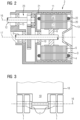
- FIG 2 shows the transmission-motor unit, which is accommodated in the axle housing 11, in a basic longitudinal section.
- the laminated core 7 of the rotor 5 is positioned on a support structure 6 which is essentially double-T-shaped.
- the center piece is designed like a spoke to reduce inertia.
- a liquid cooling jacket is provided there between the laminated core 8 of the stator 4 .
- the engine compartment is separated from the gear compartment, so that the gear can be provided with oil, while the engine compartment has air cooling, in particular a closed one.
- Bearings shown are only examples of ball bearings.
- other bearings or bearing assemblies with the respective Rolling elements which can act as fixed or floating bearings.
- These include angular contact ball bearings (single row, double row %), cylindrical roller bearings or barrel bearings. When installed in pairs, these can be arranged in an O arrangement or an X arrangement.
- FIG. 3 shows an electric axle with two gear motor units, each driving a wheel assembly 1. Due to the structure according to the invention, a compact arrangement can now be provided, which thus increases the usable volume of a commercial vehicle. In particular, this arrangement allows the aisle in an E-bus 18 to be wider.
- the representation according to FIG 4 shows the rotor 5 of the dynamoelectric machine 3 in cross section.
- the rotor 5 has a circular structure on the outside.
- the circular structure referred to as the outer annulus serves as a means for taking moments on the rotor 5.
- Moments result from means for exciting the rotor 5. If these means are already on the rotor, which is shown in FIG 4 is not the case, these are then part of the rotor 5.
- Means for excitation are, for example, permanent magnets or electrical conductors which, for example, form a cage in the case of asynchronous machines or carry a supplied current in the case of synchronous machines.
- FIG 4 shown outer circular ring, which represents the means for taking the moment.
- the moment-taking means on the rotor 5 also serves as a flux-guiding area. This area will be in FIG 4 referred to as flux guide ring 50, which is the outer ring and corresponds to the means for taking the moment on the rotor 5 .
- the rotor 5 can be designed as a series of several rotor laminations in this embodiment, means are to be provided for connecting these rotor laminations to one another. Such a connection can be carried out, among other things, via holding holes 16, in that a holding rod, for example, is passed through these, with the aid of which rotor laminations are held together. Holding holes 16 are distributed on the inner radius of the flux guide ring 50 . A symmetrical distribution is advantageous in order to also absorb occurring forces symmetrically.
- FIG 4 shows an embodiment with a number of six secants, which have a connection to the flux guide ring 50 in the area of the two holding holes 63 and form a polygon inside the rotor 5 .
- the polygon is designed as a polygon ring 48 .
- the transmission input shaft 9 is located in the central circular recess. Forces that occur in the process are then further guided through these secant-like webs 62 into the interior of the polygon ring 48 .
- the polygonal ring 48 can be connected in a rotationally fixed manner to the transmission input shaft 9 by means of a key combination, for example.
- a power transmission between the polygonal ring 48 and the transmission input shaft 9 is not limited solely to feather key combinations, since other mechanisms for power/torque transmission can also be used. These are, for example, material connections, for example by gluing or welding, or form-fitting connections such as feather keys, but in a different geometric form, such as polygons or non-positive connections in which, for example, the rotor 5 is shrunk onto the transmission input shaft 9 .
- secant webs 62 provides inertia reducing means.
- the associated weight reduction changes the moment of inertia in a positive way, so that a dynamoelectric machine 3 with the corresponding rotor 5 gains dynamics, among other things.
- Decreased weight, i.e. less mass of a body reduces the inertia of the body.
- the reduction in inertia results not only from the general weight reduction, but also in particular from the location and position of those points on the rotor at which a weight reduction takes place.
- the rotor 5 is the rotating system. Since recesses are made possible, in particular on the outer sides of the rotor, by the secant-like webs 62 lying on the outside, the moment of inertia of the entire rotor 5 is greatly reduced.
- the rotor 5 according to FIG 4 is functionally divided into three parts as described.
- the part that carries the magnetic flux carries the magnets and is referred to as the flux guide ring 50 .
- the part that transmits the moment from the magnets or the excitation or the feedback components to the shaft and in FIG 4 is represented by the secant-like webs 62.
- the third part of a rough subdivision forms the connection to the transmission input shaft 9, which is in the FIG 4 is referred to as a polygonal ring 48 and forms the means for power transmission between the rotor 5 and the transmission input shaft 9 .
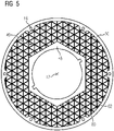
- the representation according to 5 shows the cross-section of the rotor 5 with a means for moment recording on the rotor 5, a flux guide ring 50, holding holes 63 and a polygonal ring 48.
- the power transmission from the polygonal ring 48 to the transmission input shaft 9 also takes place via a feather key combination.
- the strength of the rotor 5 can be increased by increasing the number of webs and partial webs that form this honeycomb structure 49 . Due to the larger number of secant-like webs and/or partial webs, a more homogeneous transfer of force to the webs/partial webs or from these to the polygonal ring 48 can be achieved. A reduction in the material thickness of the flux guide ring 50 and/or the polygon ring 48 is thus made possible. This in turn reduces the moment of inertia.
- the rigidity can be influenced by the design of webs and partial webs or also by the choice of the material from which the webs are made. If a honeycomb structure 49 is designed with flexible webs, the rotor 5 acts as a damper or spring between the motor and the load driven by the motor. The flexibility of the honeycomb structure 49 can also result from a flexibility of the connection points between the webs.
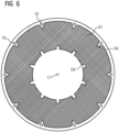
- the representation according to 6 Figure 1 shows a rotor 5 with means for taking moments, holding holes 63, as in previous figures.
- the honeycomb structure 49 according to 5 is in 6 executed in an advantageous embodiment as a honeycomb foam structure 61.
- the difference to 5 is that the chambers of the honeycomb have shrunk enormously and are closed.
- Foams in particular are inexpensive materials and very different in their properties. In this way, depending on the application, a firm or rigid foam with little or no spring or damping properties can be used.
- a soft, flexible foam has strong or large spring or damping properties.
- the power transmission from the means for absorbing moments on the rotor 5 to the foam takes place, for example, via form-fitting means 64 for power transmission, which are located outside in 6 are designed as wedges.
- the power transmission to the in 6 Transmission input shaft 9, not shown, takes place via shaft-hub connections that are known per se.
- Permanent magnets are positioned on or in the flux guide ring 50, which here represent the means of excitation. External permanent magnets are advantageously connected to the flux guide ring 50 via a bandage.
- the flux guide ring can be designed as a laminated core.
- the bandage absorbs the centrifugal forces of the permanent magnets during rotary movements, which are arranged on the surface of the flux guide ring.
Landscapes
- Engineering & Computer Science (AREA)
- Chemical & Material Sciences (AREA)
- Combustion & Propulsion (AREA)
- Transportation (AREA)
- Mechanical Engineering (AREA)
- Power Engineering (AREA)
- Connection Of Motors, Electrical Generators, Mechanical Devices, And The Like (AREA)
Priority Applications (4)
| Application Number | Priority Date | Filing Date | Title |
|---|---|---|---|
| EP21199482.7A EP4155105A1 (fr) | 2021-09-28 | 2021-09-28 | Essieu électrique |
| PCT/EP2022/072392 WO2023051984A1 (fr) | 2021-09-28 | 2022-08-10 | Essieu entraîné électriquement |
| US18/693,569 US20240399851A1 (en) | 2021-09-28 | 2022-08-10 | Electrically driven axle |
| CN202280065485.5A CN118019655A (zh) | 2021-09-28 | 2022-08-10 | 电驱动桥 |
Applications Claiming Priority (1)
| Application Number | Priority Date | Filing Date | Title |
|---|---|---|---|
| EP21199482.7A EP4155105A1 (fr) | 2021-09-28 | 2021-09-28 | Essieu électrique |
Publications (1)
| Publication Number | Publication Date |
|---|---|
| EP4155105A1 true EP4155105A1 (fr) | 2023-03-29 |
Family
ID=78134755
Family Applications (1)
| Application Number | Title | Priority Date | Filing Date |
|---|---|---|---|
| EP21199482.7A Pending EP4155105A1 (fr) | 2021-09-28 | 2021-09-28 | Essieu électrique |
Country Status (4)
| Country | Link |
|---|---|
| US (1) | US20240399851A1 (fr) |
| EP (1) | EP4155105A1 (fr) |
| CN (1) | CN118019655A (fr) |
| WO (1) | WO2023051984A1 (fr) |
Cited By (3)
| Publication number | Priority date | Publication date | Assignee | Title |
|---|---|---|---|---|
| DE102023208746A1 (de) * | 2023-09-11 | 2025-03-13 | Zf Friedrichshafen Ag | Elektrische Antriebseinheit und Fahrzeug mit elektrischer Antriebseinheit |
| US12496901B2 (en) | 2022-08-24 | 2025-12-16 | Kessler & Co. Gmbh & Co. Kg | Wheel side with offset gear and separate lubrication spaces |
| US12556075B2 (en) | 2022-08-24 | 2026-02-17 | Kessler & Co. Gmbh & Co. Kg | Wheel side |
Families Citing this family (1)
| Publication number | Priority date | Publication date | Assignee | Title |
|---|---|---|---|---|
| US12589644B2 (en) * | 2023-12-19 | 2026-03-31 | Arvinmeritor Technology, Llc | Drive axle system having an electric motor |
Citations (6)
| Publication number | Priority date | Publication date | Assignee | Title |
|---|---|---|---|---|
| EP0249807A1 (fr) * | 1986-06-18 | 1987-12-23 | Magnet-Motor Gesellschaft für magnetmotorische Technik mbH | Entraînement électrique pour véhicules automobiles |
| DE4421425C1 (de) * | 1994-06-18 | 1995-08-10 | Fichtel & Sachs Ag | Elektrisches Antriebsaggregat für ein Fahrzeug |
| WO2001003963A1 (fr) * | 1999-07-13 | 2001-01-18 | Zf Friedrichshafen Ag | Pont comportant un corps de pont situe sous l'essieu |
| DE10126340A1 (de) * | 2001-05-30 | 2002-12-12 | Siemens Ag | Elektrische Maschine mit trägheitsarmen Läufer |
| EP1329352A2 (fr) * | 2002-01-18 | 2003-07-23 | Voith Turbo GmbH & Co. KG | Ensemble entraínement, en particulier pour véhicules utilitaires |
| CN110588310A (zh) | 2019-09-27 | 2019-12-20 | 上海中科深江电动车辆有限公司 | 电驱动装置 |
Family Cites Families (1)
| Publication number | Priority date | Publication date | Assignee | Title |
|---|---|---|---|---|
| CN107013654B (zh) * | 2017-04-21 | 2023-04-07 | 吉林大学 | 一种带有转矩定向分配功能的电动差速器 |
-
2021
- 2021-09-28 EP EP21199482.7A patent/EP4155105A1/fr active Pending
-
2022
- 2022-08-10 WO PCT/EP2022/072392 patent/WO2023051984A1/fr not_active Ceased
- 2022-08-10 US US18/693,569 patent/US20240399851A1/en active Pending
- 2022-08-10 CN CN202280065485.5A patent/CN118019655A/zh active Pending
Patent Citations (6)
| Publication number | Priority date | Publication date | Assignee | Title |
|---|---|---|---|---|
| EP0249807A1 (fr) * | 1986-06-18 | 1987-12-23 | Magnet-Motor Gesellschaft für magnetmotorische Technik mbH | Entraînement électrique pour véhicules automobiles |
| DE4421425C1 (de) * | 1994-06-18 | 1995-08-10 | Fichtel & Sachs Ag | Elektrisches Antriebsaggregat für ein Fahrzeug |
| WO2001003963A1 (fr) * | 1999-07-13 | 2001-01-18 | Zf Friedrichshafen Ag | Pont comportant un corps de pont situe sous l'essieu |
| DE10126340A1 (de) * | 2001-05-30 | 2002-12-12 | Siemens Ag | Elektrische Maschine mit trägheitsarmen Läufer |
| EP1329352A2 (fr) * | 2002-01-18 | 2003-07-23 | Voith Turbo GmbH & Co. KG | Ensemble entraínement, en particulier pour véhicules utilitaires |
| CN110588310A (zh) | 2019-09-27 | 2019-12-20 | 上海中科深江电动车辆有限公司 | 电驱动装置 |
Cited By (3)
| Publication number | Priority date | Publication date | Assignee | Title |
|---|---|---|---|---|
| US12496901B2 (en) | 2022-08-24 | 2025-12-16 | Kessler & Co. Gmbh & Co. Kg | Wheel side with offset gear and separate lubrication spaces |
| US12556075B2 (en) | 2022-08-24 | 2026-02-17 | Kessler & Co. Gmbh & Co. Kg | Wheel side |
| DE102023208746A1 (de) * | 2023-09-11 | 2025-03-13 | Zf Friedrichshafen Ag | Elektrische Antriebseinheit und Fahrzeug mit elektrischer Antriebseinheit |
Also Published As
| Publication number | Publication date |
|---|---|
| CN118019655A (zh) | 2024-05-10 |
| WO2023051984A1 (fr) | 2023-04-06 |
| US20240399851A1 (en) | 2024-12-05 |
Similar Documents
| Publication | Publication Date | Title |
|---|---|---|
| DE102021101904B3 (de) | Elektrische Maschine mit einem mechanischen Feldschwächungsmodul | |
| WO2023051984A1 (fr) | Essieu entraîné électriquement | |
| EP0706461B1 (fr) | Unite d'entrainement | |
| EP1320478B1 (fr) | Entrainement direct d'un essieu monte | |
| EP2199137B1 (fr) | Agencement de moteur latéral à la roue | |
| DE102016222844A1 (de) | Reibungsoptimiertes elektrisches Antriebssystem | |
| DE102016207996A1 (de) | Elektrische Maschine zum Antrieb eines Fahrzeugs | |
| DE102020107570A1 (de) | Antriebsanordnung für eine elektrische Antriebsachse mit zwei Motoren | |
| DE102021101900A1 (de) | Elektrische Maschine und Antriebsstrang für ein hybrid- oder vollelektrisch antreibbares Kraftfahrzeug | |
| EP2520009A2 (fr) | Entraînement électrique à transmission à vis sans fin | |
| WO2020164995A1 (fr) | Machine électrique | |
| DE102015213609A1 (de) | Hochdynamisch betreibbarer Rotor für eine elektrische Maschine | |
| DE102022114472A1 (de) | Axialflussmaschine, elektrischer Achsantriebsstrang und Kraftfahrzeug | |
| DE10310777A1 (de) | Elektromaschine mit koaxialen, mehrfach abwechselnden Magnet- und Wicklungslagen | |
| DE102011005617A1 (de) | Antriebsvorrichtung zum Antreiben eines Rades für ein elektrisch antreibbares Fahrzeug | |
| DE102006049327A1 (de) | Rollenantriebssystem mit Schwingungsdämpfung | |
| DE102024001297A1 (de) | Radnabenantrieb für ein Kraftfahrzeug sowie Kraftfahrzeug | |
| EP1477380B1 (fr) | Moteur d'entraînement électique à arbre creux | |
| DE102023200463A1 (de) | Antriebsstrang für eine Antriebsachse eines Fahrzeugs, Antriebsachse sowie Fahrzeug mit einer solchen Antriebsachse | |
| DE102022213049A1 (de) | Antriebsstrang, Antriebsachse und Fahrzeug mit einem solchen Antriebsstrang und/oder einer solchen Antriebsachse | |
| EP4480072A1 (fr) | Machine à flux axial, chaîne cinématique à essieu électrique et véhicule à moteur | |
| DE102021108905A1 (de) | Elektrische Maschine | |
| DE102015107163A1 (de) | Antrieb eines muskelbetriebenen Fahrzeugs mit integriertem und entkoppelbarem Elektroantrieb | |
| DE102021127658A1 (de) | Elektrische Maschine für ein Kraftfahrzeug | |
| WO2019052767A1 (fr) | Véhicule d'exploitation minière à entraînement sur moyeu de roue |
Legal Events
| Date | Code | Title | Description |
|---|---|---|---|
| PUAI | Public reference made under article 153(3) epc to a published international application that has entered the european phase |
Free format text: ORIGINAL CODE: 0009012 |
|
| STAA | Information on the status of an ep patent application or granted ep patent |
Free format text: STATUS: THE APPLICATION HAS BEEN PUBLISHED |
|
| AK | Designated contracting states |
Kind code of ref document: A1 Designated state(s): AL AT BE BG CH CY CZ DE DK EE ES FI FR GB GR HR HU IE IS IT LI LT LU LV MC MK MT NL NO PL PT RO RS SE SI SK SM TR |
|
| STAA | Information on the status of an ep patent application or granted ep patent |
Free format text: STATUS: REQUEST FOR EXAMINATION WAS MADE |
|
| 17P | Request for examination filed |
Effective date: 20230929 |
|
| RBV | Designated contracting states (corrected) |
Designated state(s): AL AT BE BG CH CY CZ DE DK EE ES FI FR GB GR HR HU IE IS IT LI LT LU LV MC MK MT NL NO PL PT RO RS SE SI SK SM TR |
|
| TPAC | Observations filed by third parties |
Free format text: ORIGINAL CODE: EPIDOSNTIPA |
|
| STAA | Information on the status of an ep patent application or granted ep patent |
Free format text: STATUS: EXAMINATION IS IN PROGRESS |
|
| 17Q | First examination report despatched |
Effective date: 20250724 |
|
| GRAP | Despatch of communication of intention to grant a patent |
Free format text: ORIGINAL CODE: EPIDOSNIGR1 |
|
| STAA | Information on the status of an ep patent application or granted ep patent |
Free format text: STATUS: GRANT OF PATENT IS INTENDED |