EP4155111A1 - Boîtier de système d'un module d'axe électrique - Google Patents
Boîtier de système d'un module d'axe électrique Download PDFInfo
- Publication number
- EP4155111A1 EP4155111A1 EP22195153.6A EP22195153A EP4155111A1 EP 4155111 A1 EP4155111 A1 EP 4155111A1 EP 22195153 A EP22195153 A EP 22195153A EP 4155111 A1 EP4155111 A1 EP 4155111A1
- Authority
- EP
- European Patent Office
- Prior art keywords
- system housing
- power electronics
- housing
- cooling
- stator winding
- Prior art date
- Legal status (The legal status is an assumption and is not a legal conclusion. Google has not performed a legal analysis and makes no representation as to the accuracy of the status listed.)
- Granted
Links
Images


Classifications
-
- H—ELECTRICITY
- H02—GENERATION; CONVERSION OR DISTRIBUTION OF ELECTRIC POWER
- H02K—DYNAMO-ELECTRIC MACHINES
- H02K11/00—Structural association of dynamo-electric machines with electric components or with devices for shielding, monitoring or protection
- H02K11/30—Structural association with control circuits or drive circuits
- H02K11/33—Drive circuits, e.g. power electronics
-
- B—PERFORMING OPERATIONS; TRANSPORTING
- B60—VEHICLES IN GENERAL
- B60K—ARRANGEMENT OR MOUNTING OF PROPULSION UNITS OR OF TRANSMISSIONS IN VEHICLES; ARRANGEMENT OR MOUNTING OF PLURAL DIVERSE PRIME-MOVERS IN VEHICLES; AUXILIARY DRIVES FOR VEHICLES; INSTRUMENTATION OR DASHBOARDS FOR VEHICLES; ARRANGEMENTS IN CONNECTION WITH COOLING, AIR INTAKE, GAS EXHAUST OR FUEL SUPPLY OF PROPULSION UNITS IN VEHICLES
- B60K11/00—Arrangement in connection with cooling of propulsion units
- B60K11/02—Arrangement in connection with cooling of propulsion units with liquid cooling
-
- B—PERFORMING OPERATIONS; TRANSPORTING
- B60—VEHICLES IN GENERAL
- B60L—PROPULSION OF ELECTRICALLY-PROPELLED VEHICLES; SUPPLYING ELECTRIC POWER FOR AUXILIARY EQUIPMENT OF ELECTRICALLY-PROPELLED VEHICLES; ELECTRODYNAMIC BRAKE SYSTEMS FOR VEHICLES IN GENERAL; MAGNETIC SUSPENSION OR LEVITATION FOR VEHICLES; MONITORING OPERATING VARIABLES OF ELECTRICALLY-PROPELLED VEHICLES; ELECTRIC SAFETY DEVICES FOR ELECTRICALLY-PROPELLED VEHICLES
- B60L1/00—Supplying electric power to auxiliary equipment of vehicles
- B60L1/02—Supplying electric power to auxiliary equipment of vehicles to electric heating circuits
- B60L1/04—Supplying electric power to auxiliary equipment of vehicles to electric heating circuits fed by the power supply line
- B60L1/06—Supplying electric power to auxiliary equipment of vehicles to electric heating circuits fed by the power supply line using only one supply
-
- B—PERFORMING OPERATIONS; TRANSPORTING
- B60—VEHICLES IN GENERAL
- B60L—PROPULSION OF ELECTRICALLY-PROPELLED VEHICLES; SUPPLYING ELECTRIC POWER FOR AUXILIARY EQUIPMENT OF ELECTRICALLY-PROPELLED VEHICLES; ELECTRODYNAMIC BRAKE SYSTEMS FOR VEHICLES IN GENERAL; MAGNETIC SUSPENSION OR LEVITATION FOR VEHICLES; MONITORING OPERATING VARIABLES OF ELECTRICALLY-PROPELLED VEHICLES; ELECTRIC SAFETY DEVICES FOR ELECTRICALLY-PROPELLED VEHICLES
- B60L3/00—Electric devices on electrically-propelled vehicles for safety purposes; Monitoring operating variables, e.g. speed, deceleration or energy consumption
- B60L3/0023—Detecting, eliminating, remedying or compensating for drive train abnormalities, e.g. failures within the drive train
- B60L3/0061—Detecting, eliminating, remedying or compensating for drive train abnormalities, e.g. failures within the drive train relating to electrical machines
-
- H—ELECTRICITY
- H02—GENERATION; CONVERSION OR DISTRIBUTION OF ELECTRIC POWER
- H02K—DYNAMO-ELECTRIC MACHINES
- H02K5/00—Casings; Enclosures; Supports
- H02K5/04—Casings or enclosures characterised by the shape, form or construction thereof
- H02K5/10—Casings or enclosures characterised by the shape, form or construction thereof with arrangements for protection from ingress, e.g. water or fingers
-
- H—ELECTRICITY
- H02—GENERATION; CONVERSION OR DISTRIBUTION OF ELECTRIC POWER
- H02K—DYNAMO-ELECTRIC MACHINES
- H02K5/00—Casings; Enclosures; Supports
- H02K5/04—Casings or enclosures characterised by the shape, form or construction thereof
- H02K5/15—Mounting arrangements for bearing-shields or end plates
-
- H—ELECTRICITY
- H02—GENERATION; CONVERSION OR DISTRIBUTION OF ELECTRIC POWER
- H02K—DYNAMO-ELECTRIC MACHINES
- H02K5/00—Casings; Enclosures; Supports
- H02K5/04—Casings or enclosures characterised by the shape, form or construction thereof
- H02K5/18—Casings or enclosures characterised by the shape, form or construction thereof with ribs or fins for improving heat transfer
-
- H—ELECTRICITY
- H02—GENERATION; CONVERSION OR DISTRIBUTION OF ELECTRIC POWER
- H02K—DYNAMO-ELECTRIC MACHINES
- H02K5/00—Casings; Enclosures; Supports
- H02K5/04—Casings or enclosures characterised by the shape, form or construction thereof
- H02K5/20—Casings or enclosures characterised by the shape, form or construction thereof with channels or ducts for flow of cooling medium
- H02K5/203—Casings or enclosures characterised by the shape, form or construction thereof with channels or ducts for flow of cooling medium specially adapted for liquids, e.g. cooling jackets
-
- H—ELECTRICITY
- H02—GENERATION; CONVERSION OR DISTRIBUTION OF ELECTRIC POWER
- H02K—DYNAMO-ELECTRIC MACHINES
- H02K5/00—Casings; Enclosures; Supports
- H02K5/04—Casings or enclosures characterised by the shape, form or construction thereof
- H02K5/22—Auxiliary parts of casings not covered by groups H02K5/06-H02K5/20, e.g. shaped to form connection boxes or terminal boxes
-
- H—ELECTRICITY
- H02—GENERATION; CONVERSION OR DISTRIBUTION OF ELECTRIC POWER
- H02K—DYNAMO-ELECTRIC MACHINES
- H02K7/00—Arrangements for handling mechanical energy structurally associated with dynamo-electric machines, e.g. structural association with mechanical driving motors or auxiliary dynamo-electric machines
- H02K7/10—Structural association with clutches, brakes, gears, pulleys or mechanical starters
- H02K7/116—Structural association with clutches, brakes, gears, pulleys or mechanical starters with gears
-
- H—ELECTRICITY
- H02—GENERATION; CONVERSION OR DISTRIBUTION OF ELECTRIC POWER
- H02K—DYNAMO-ELECTRIC MACHINES
- H02K9/00—Arrangements for cooling or ventilating
- H02K9/19—Arrangements for cooling or ventilating for machines with closed casing and closed-circuit cooling using a liquid cooling medium, e.g. oil
-
- B—PERFORMING OPERATIONS; TRANSPORTING
- B60—VEHICLES IN GENERAL
- B60K—ARRANGEMENT OR MOUNTING OF PROPULSION UNITS OR OF TRANSMISSIONS IN VEHICLES; ARRANGEMENT OR MOUNTING OF PLURAL DIVERSE PRIME-MOVERS IN VEHICLES; AUXILIARY DRIVES FOR VEHICLES; INSTRUMENTATION OR DASHBOARDS FOR VEHICLES; ARRANGEMENTS IN CONNECTION WITH COOLING, AIR INTAKE, GAS EXHAUST OR FUEL SUPPLY OF PROPULSION UNITS IN VEHICLES
- B60K1/00—Arrangement or mounting of electrical propulsion units
- B60K2001/001—Arrangement or mounting of electrical propulsion units one motor mounted on a propulsion axle for rotating right and left wheels of this axle
-
- B—PERFORMING OPERATIONS; TRANSPORTING
- B60—VEHICLES IN GENERAL
- B60K—ARRANGEMENT OR MOUNTING OF PROPULSION UNITS OR OF TRANSMISSIONS IN VEHICLES; ARRANGEMENT OR MOUNTING OF PLURAL DIVERSE PRIME-MOVERS IN VEHICLES; AUXILIARY DRIVES FOR VEHICLES; INSTRUMENTATION OR DASHBOARDS FOR VEHICLES; ARRANGEMENTS IN CONNECTION WITH COOLING, AIR INTAKE, GAS EXHAUST OR FUEL SUPPLY OF PROPULSION UNITS IN VEHICLES
- B60K1/00—Arrangement or mounting of electrical propulsion units
- B60K2001/003—Arrangement or mounting of electrical propulsion units with means for cooling the electrical propulsion units
- B60K2001/006—Arrangement or mounting of electrical propulsion units with means for cooling the electrical propulsion units the electric motors
-
- B—PERFORMING OPERATIONS; TRANSPORTING
- B60—VEHICLES IN GENERAL
- B60L—PROPULSION OF ELECTRICALLY-PROPELLED VEHICLES; SUPPLYING ELECTRIC POWER FOR AUXILIARY EQUIPMENT OF ELECTRICALLY-PROPELLED VEHICLES; ELECTRODYNAMIC BRAKE SYSTEMS FOR VEHICLES IN GENERAL; MAGNETIC SUSPENSION OR LEVITATION FOR VEHICLES; MONITORING OPERATING VARIABLES OF ELECTRICALLY-PROPELLED VEHICLES; ELECTRIC SAFETY DEVICES FOR ELECTRICALLY-PROPELLED VEHICLES
- B60L2210/00—Converter types
- B60L2210/40—DC to AC converters
-
- H—ELECTRICITY
- H02—GENERATION; CONVERSION OR DISTRIBUTION OF ELECTRIC POWER
- H02K—DYNAMO-ELECTRIC MACHINES
- H02K15/00—Processes or apparatus specially adapted for manufacturing, assembling, maintaining or repairing of dynamo-electric machines
- H02K15/14—Casings; Enclosures; Supports
-
- H—ELECTRICITY
- H02—GENERATION; CONVERSION OR DISTRIBUTION OF ELECTRIC POWER
- H02K—DYNAMO-ELECTRIC MACHINES
- H02K2213/00—Specific aspects, not otherwise provided for and not covered by codes H02K2201/00 - H02K2211/00
- H02K2213/12—Machines characterised by the modularity of some components
-
- H—ELECTRICITY
- H02—GENERATION; CONVERSION OR DISTRIBUTION OF ELECTRIC POWER
- H02K—DYNAMO-ELECTRIC MACHINES
- H02K5/00—Casings; Enclosures; Supports
- H02K5/04—Casings or enclosures characterised by the shape, form or construction thereof
- H02K5/16—Means for supporting bearings, e.g. insulating supports or means for fitting bearings in the bearing-shields
- H02K5/173—Means for supporting bearings, e.g. insulating supports or means for fitting bearings in the bearing-shields using bearings with rolling contact, e.g. ball bearings
- H02K5/1732—Means for supporting bearings, e.g. insulating supports or means for fitting bearings in the bearing-shields using bearings with rolling contact, e.g. ball bearings radially supporting the rotary shaft at both ends of the rotor
-
- H—ELECTRICITY
- H02—GENERATION; CONVERSION OR DISTRIBUTION OF ELECTRIC POWER
- H02K—DYNAMO-ELECTRIC MACHINES
- H02K7/00—Arrangements for handling mechanical energy structurally associated with dynamo-electric machines, e.g. structural association with mechanical driving motors or auxiliary dynamo-electric machines
- H02K7/08—Structural association with bearings
- H02K7/083—Structural association with bearings radially supporting the rotary shaft at both ends of the rotor
Definitions
- the invention relates to a system housing of an e-axis module with a stator winding and a rotor of an electrical machine, which is mounted in at least a first bearing plate and a second bearing plate. Furthermore, the invention relates to the use of the system housing of an e-axle module in an electrically powered vehicle.
- E-axle modules usually have housings made as cast components, which on the one hand are complex to produce as a primary shaping component and on the other hand have a relatively high weight.
- Cast components on the other hand, have good thermal conductivity properties and can be adapted to a wide variety of operating conditions and manufactured individually, which, however, stands in the way of large-scale production.
- modular transmission housings are known, but they have the disadvantage that they have a large number of components, which makes assembly considerably more expensive and involves a large number of interfaces that can lead to incorrect assembly steps during the assembly of such housings.
- a system housing of an e-axis module having a stator winding and a rotor an electrical machine, which is mounted in at least a first bearing plate and a second bearing plate.
- the system housing proposed according to the invention is designed as a double-walled, extruded housing that includes a channel system that extends below a cooling surface of a mounting space for power electronics.
- the system housing proposed according to the invention which can be designed in particular as a double-walled, extruded profile, provides a cost-effective component suitable for large-scale production, which is characterized by an external geometry on which a large number of bearing and damping elements as well as fastening elements can be provided at different points
- a wide variety of installation conditions can be adapted, which makes it possible to achieve a very high degree of flexibility while at the same time being inexpensive to manufacture.
- this has an external geometry which has a number of ribs running essentially in the longitudinal direction of the system housing. These ribs, since they are designed to be spaced apart from one another in the circumferential direction of the system housing, can serve as attachment points both for bearing and damping elements and for attachment elements on the vehicle body.
- At least one bearing and/or damping element and at least one fastening element are arranged on the outer geometry of the system housing. Since these can be moved laterally on the outer geometry in the longitudinal direction of the system housing, individual customer requirements can be taken into account with regard to the installation location or with regard to the interfaces to be provided between the system housing of the e-axle module and the vehicle or the vehicle body.
- the external geometry of the system housing proposed according to the invention is such that it includes, in particular, a number of grooves, which are preferably designed as longitudinal grooves.
- This also allows the advantages of an essentially double-walled, as Extruded extruded profile trained system housing can be used, since the grooves can be introduced directly into the housing, during its production as a continuously cast component.
- the grooves extending over the entire length in the longitudinal direction of the system housing are continuous, so that fastening points can be provided at different points within the individual grooves, which also entails a high degree of variance in the system housing proposed according to the invention and can be flexibly adapted to the most diverse customer requirements can.
- the system housing proposed according to the invention is further characterized in that the cooling duct system comprises at least one cooling ribbing below the cooling surface of the mounting space for the power electronics.
- the system of cooling ducts running through the double-walled, extruded system housing not only cools the jacket of the system housing, but also enables cooling of the cooling surface of the space for the power electronics that is integrated into the system housing. If cooling ribbing is provided below the receiving surface for a lower planar surface of the component of the power electronics, a considerably improved heat transport of waste heat produced by the power electronics during its operation can be guaranteed. This means that the cooling system proposed according to the invention can be used for targeted, effective cooling at locations where a high level of waste heat production occurs.
- the cooling channel system has either an opening in the area of the cooling surface for direct cooling of the power electronics or the cooling surface of the power electronics can be temperature-controlled indirectly via the cooling ribbing already mentioned above below the cooling surface.
- this has an additional bearing support which can be mounted centrally in this and which holds the rotor of the electrical machine between the Stator winding in the system housing on the one hand and the gear assembly on the rotor shaft of the rotor on the other hand and also separates these components from each other.
- the bearing bracket which is installed essentially in the middle of the system housing, not only creates an additional storage option for the rotor shaft of the rotor of the electrical machine, but also a "wet-running" part in which the gear arrangement is housed from the "dry " part of the rotor of the electrical machine must be separated. Accordingly, the additional bearing bracket not only performs an additional support function but also separates the wet part from the dry part within the system housing of the e-axis module.
- the system housing proposed according to the invention can be designed in such a way that the power electronics are mounted essentially in the vertical direction in the installation space provided in the system housing, with the power electronics having contact openings which move into contact openings for the stator winding in the vertical direction during installation.
- this can be configured in such a way that the power electronics are pushed laterally into the assembly space essentially in the horizontal direction, ie can be designed as a slide-in part.
- both the contacts of the power electronics and their contact openings to the stator winding can be designed in an oblique orientation, so that the contacts during lateral assembly, i. H. the lateral insertion of the power electronics into the assembly space, contact the contact openings to the stator winding directly.
- an electrical contact can alternatively also be established between the power electronics and the stator winding via at least one contacting part.
- the invention relates to the use of the system housing of an e-axle module in an electrically powered vehicle.
- the outer geometry can be used for individual fastening.
- the external geometry of the system housing proposed according to the invention comprises ribs which extend essentially continuously, viewed in the longitudinal direction of the system housing, and which are spaced apart from one another, viewed in the circumferential direction of the system housing.
- the system housing proposed according to the invention has a considerable weight advantage compared to housings produced in the primary molding process of casting. Furthermore, the interfaces are significantly reduced by minimizing components, so that errors during assembly can be almost completely ruled out.
- the double-walled, extruded system housing comprises at least two lateral bearing plates which close it and in which bearings for accommodating the rotor of the electrical machine are accommodated.
- the system housing proposed according to the invention is characterized in that a mounting space for the power electronics is integrated into it and a cooling surface delimiting the mounting space for accommodating the power electronics the cooling channel system of the system housing proposed according to the invention is integrated.
- the power electronics can be cooled directly through an opening in the cooling surface; on the other hand, there is alternatively the possibility of indirectly cooling the power electronics by providing at least one cooling ribbing within the cooling surface by dissipating heat from its underside to the cooling surface into the cooling fluid.
- the solution proposed according to the invention allows both variants of cooling, ie direct and indirect cooling.
- the power electronics can be installed in the installation space essentially in the vertical direction, i. H. from the top of the system case.
- a horizontal direction i. H. to be installed as a slide-in component in the installation space for the power electronics.
- the contacts which are preferably carried out on the underside of the power electronics, can be contacted directly with contact openings in the stator winding in the system housing.
- the lateral end shields of the system housing, which seal its cavity, can also be advantageously designed in such a way that these cover parts and lateral closing surfaces of the installation space for the power electronics in the system housing.
- an additional bearing support can be provided approximately centrally in the system housing in the bearing points of the rotor in the end shields, which bearing support additionally supports the rotor shaft of the rotor of the electrical machine.
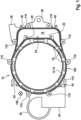
- a system housing 12 of an E-axis module 10 designed according to the invention can be seen.
- the system housing 12 is a double-walled, extruded housing 14, in particular a continuously cast component.
- a cooling channel system 16 runs through the double wall of the extruded housing 14, as shown in FIG figure 1 emerges.
- On the system housing 12 there is a mounting space 18 for accommodating power electronics, not shown in detail here.
- An external geometry 106 is formed on the system housing 12 proposed according to the invention.
- the outer geometry 106 extends essentially to the longitudinal direction 108 running perpendicular to the plane of the drawing.
- the outer geometry 106 can preferably be formed by a number of ribs 110 .
- the outer geometry 106 of the extruded housing 14, which serves as the system housing 12, includes a first groove 20 and a second groove 22. These likewise extend into the plane of the drawing in FIG figure 1 .
- the first groove 20 and the second groove 22 delimit a cooling surface 24.
- the underside of an essentially flat power electronics system is applied to this surface and fixed by means of the grooves 20, 22.
- On the outer geometry 106 of the system housing 12 are a first fastening element 26 and a second Fastener 28 shown.
- bearing and/or damping elements 34 , 36 are arranged on the outer geometry 106 .
- the system housing 12 of the e-axis module 10 can be fastened or mounted at fastening points provided individually on the vehicle. Since the outer geometry 106 of the system housing 12 has the ribs 110 extending in the longitudinal direction 108, an individual positioning of the fastening elements 26, 28 or the bearing and/or damping elements 34, 36 is possible in an individual way.
- the outer geometry 106 has a number of grooves, namely a first longitudinal groove 38 , a second longitudinal groove 40 , a third longitudinal groove 42 and a fourth longitudinal groove 44 .
- the longitudinal grooves 38, 40, 42, 44 can also be used to fix and attach the system housing 12 to individual suspension and bearing points in the vehicle.
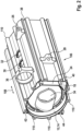
- figure 2 12 shows a perspective view of the system housing 12 according to FIG figure 1 .
- the mounting space 18 for accommodating power electronics is integrated into the system housing 12 designed as a double-walled extruded housing 14 .
- the fasteners 26, 28 are provided at individual locations;
- the bearings and/or damping elements 34, 36 which are also arranged between adjacent ribs 110 of the outer geometry 106, which ribs extend in the longitudinal direction 108. Due to the longitudinal extension of the ribs 110 parallel to the longitudinal direction 108 of the extruded housing 14, there are different, individual positioning options and thus flexible individual solutions for fastening the system housing 12 of the E-axis module 10 proposed according to the invention.
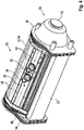
- figure 3 shows the course of a coolant flow through the double-walled extruded housing 14.
- the system housing 12 preferably designed as a double-walled, extruded housing 14 of an extrusion profile, has the cooling channel system 16, through which the cooling fluid flow 46 flows.
- the cooling fluid flow 46 passes through an area below the cooling surface 24, in which at least one cooling ribbing 48 is arranged. This improves the heat transfer from the in figure 3 power electronics, not shown, placed on the cooling surface 24 to the cooling fluid circulating in the cooling channel system 16 .
- This is fed to the cooling channel system 16 of the system housing 12 via an inlet 30 and leaves the cooling channel system 16 via an outlet 32 and transports the absorbed waste heat out of the system housing 12.
- FIG. 1 also shows the ribs 110 of the outer geometry 106 formed in the plane of the drawing, ie coinciding here with the longitudinal direction 108.
- FIG figure 3 which is also in the longitudinal direction 108 perpendicular to the plane of the drawing figure 3 extending longitudinal grooves 38, 40, 42, 44. From the illustration according to figure 3 also shows that the cooling surface 24 is delimited by the first groove 20 and the second groove 22 and the cooling surface 24 is essentially flat in order to achieve improved heat transfer.
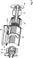
- the E-axis module 10 can be seen.
- the E-axis module 10 includes a first end shield 54 and a second end shield 56, which is designed in the shape of a bell 58.
- a stator winding 50 and a gear arrangement 52 are accommodated in the interior of the system housing 12 .
- the gear arrangement 52 can have a single-stage or multi-stage planetary gear.
- figure 4 also shows a rotor 76 of an electrical machine, on the rotor shaft of which the gear arrangement 52 is located.
- FIG 5 shows a perspective view of the second bearing plate 56, designed in the shape of a bell 58.
- the second bearing plate 56 comprises an inner axial ribbing 60 and a first ring-shaped sealing element 62, a second ring-shaped sealing element 64 and a third ring-shaped sealing element 66.
- Figures 6.1 and 6.2 illustrate the inclusion of the power electronics 70 in the mounting space 18 of the system housing 12.
- the power electronics 70 is, for example, laterally, ie in the direction of the plane of FIG Figure 6.1 pushed into the assembly space 18.
- the power electronics 70 makes contact with the cooling surface 24 with its lower planar surface. Below the cooling surface 24 there is at least one cooling ribbing 48 via which the cooling fluid dissipates waste heat which is produced during the operation of the power electronics 70 .
- Figure 6.1 FIG. 12 also shows that the power electronics 70 are fixed in their foot area, overlapped by the first groove 20 and the second groove 22 .
- the outer geometry 106 of the system housing 12, preferably designed as a double-walled extruded housing 14, has ribs 110 extending in the longitudinal direction 108 analogously to the figures described above.
- the outer geometry 106 of the system housing 12 includes the longitudinal grooves 38, 40, 42, 44, which also extend in the longitudinal direction 108, ie in the plane of the drawing Figure 6.1 extend.
- Figure 6.2 shows in detail that the first groove 20 with an overlap 72 covers the lower, broadened area of the power electronics 70 with play. As shown in the enlarged view Figure 6.2 As can be seen, the cooling ribs 48 are located below or next to the cooling surface 24, via which the waste heat transport of the waste heat that is produced during the operation of the power electronics 70 is optimized.
- FIG. 7 An exploded view of the components of the system housing 12 can be seen in FIG.
- Out of figure 7 shows that the assembly space 18 for accommodating the in figure 7 Not shown power electronics in the system housing 12, preferably formed as a double-walled extruded housing 14 is integrated.
- the cooling surface 24, which delimits the mounting space 18 for accommodating the power electronics, is provided with a housing opening 78, so that direct cooling of the figure 7 not shown, but can be placed in the assembly space 18 power electronics.
- a bearing bracket 80 In the interior of the system housing 12 there is a bearing bracket 80, via which the rotor shaft of the rotor 76 of the electrical machine can be additionally supported.
- the gear assembly 52 On one side of the bearing bracket 80 is the gear assembly 52, received in the second bearing plate 56, while on the opposite side of the bearing bracket 80, surrounded by the stator winding 50, the rotor winding of the rotor 76 is located.
- the rotor shaft of the rotor 76 is accommodated in the first end shield 54 .
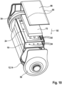
- the power electronics 70 are mounted in the vertical mounting direction 92 on the upper side of the system housing 12, designed as a double-walled extruded housing 14, in particular on the cooling surface 24.
- the power electronics 70 comprises a number of contacts 82, which pass through contact openings 84, designed in a corresponding number, and establish an electrical connection between the power electronics 70 and the in figure 13 not shown produce the stator winding 50 of the electrical machine.
- the cover 86 After the power electronics 70 have been mounted in the vertical mounting direction 92 on the upper side of the system housing 12, they are covered by means of the cover 86.
- the cover 86 encloses the power electronics 70 on all sides.
- the inlet 30 and the outlet 32 for the cooling fluid are located on the side of the system housing 12 .
- the contact openings 84 extend essentially in the vertical direction, corresponding to the extension of the contacts 82 on the underside of the power electronics 70.
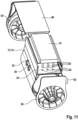
- figure 9 12 shows an embodiment variant of the system housing 12, in which the power electronics 70 are also electrically contacted in the vertical mounting direction 92 on the cooling surface 24 of the mounting space 18.
- the contacts 82 extend substantially vertically from the underside of the power electronics 70; the contact openings 84 for the stator winding 50 of the electrical machine are designed accordingly.
- the mounting space 18 for accommodating the power electronics 70 is delimited by side walls which are part of the system housing 12 which, according to the invention, is designed as a double-walled extruded housing 14 .
- the cover 86 comprises bevels 88 on the respective short sides.
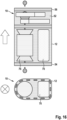
- figure 10 shows a variant of the system housing 12, whose components are shown here in an exploded view.
- the system housing 12 is through the first bearing plate 54 and the second bearing plate 56 after assembly of the components according to Figures 7 to 11 locked.
- the power electronics 70 are assembled essentially in the vertical assembly direction 92.
- the contacts 82 on the underside of the power electronics 70 are inserted into correspondingly designed contact openings 84 in the cooling surface 24 and provide an electrical connection between the power electronics 70 and the stator winding 50, not shown here, of the electrical machine.
- the cover 86 is in accordance with the embodiment variant figure 15 provided with laterally rounded bulges 90.
- figure 11 shows a variant of the system housing 12, also designed as a double-walled, extruded housing 14, in which the cover part 86 is fastened to the first bearing plate 54.
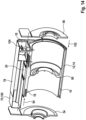
- figure 12 12 shows an embodiment variant of the system housing 12 in which the power electronics 70 are pushed into the mounting space 18 in the horizontal mounting direction 94 .
- the contacts 82 on the underside of the power electronics 70 as well as the contact openings 84 in an oblique orientation 96. This means that when the power electronics 70 are pushed in from the side, the contacts 82 arranged in an oblique orientation 96 move into the contact openings 84 and there is surface contact between the cooling surface 24 and the underside the power electronics 70 arises.
- the system housing 12 also designed here as a double-walled extruded housing 14 , is closed off by the first bearing plate 54 and the second bearing plate 56 .
- the figures 13 and 14 12 show embodiment variants of the system housing 12 proposed according to the invention, in which the power electronics 70 are designed essentially as a plug-in part 100.
- the designed as a plug-in part 100 power electronics 70 is in the horizontal mounting direction 94 in the mounting space 18 according to figures 13 and 14 pushed in sideways. According to FIG. 18, after the power electronics 70 have been pushed in, their position in the assembly space 18 can be fixed by a half-shell 98 .
- the housing opening 78 is formed so that the power electronics 70 can be cooled directly via the cooling fluid circulating in the cooling channel system 16 .
- the power electronics 70 can be cooled indirectly by the waste heat from the power electronics 70 being able to be transferred to the cooling fluid via the cooling surface 24 and cooling ribbing 48 running below it.
- Out of figure 13 shows that the bearing support 80 is arranged centrally in the system housing 12, designed as a double-walled extruded housing 14 with a cooling channel system 16, just like the stator winding 50 is let into the system housing 12.
- the mounting direction of the second end shield 56 after the half-shell 98 has been fixed is denoted by reference numeral 102 .
- figure 14 shows the assembly of the power electronics 70, also designed as an insert part 100, in the horizontal assembly direction 94 in the assembly space 18.
- the assembly space 18 is closed by the first bearing plate 54 and the second bearing plate 56.
- the additionally provided bearing bracket 80 which additionally supports the rotor shaft of the rotor 76, which is not shown here.
- at least one contacting part 104 establishes the electrical contact between the power electronics 70 and the in figure 14 not shown stator winding 50 produces.
- the power electronics 70 After the power electronics 70 have been installed in the installation space 18 , it is closed off by corresponding surfaces that are implemented on the first bearing plate 54 and on the second bearing plate 56 .
- FIG 15 12 shows an alternative embodiment of the E-axis module 10. Identical elements with respect to FIG Figures 1 to 14 are provided with the same reference numerals and are not explained in more detail.
- the gear arrangement 52 of the E-axis module 10 is designed with a spur gear.
- figure 16 12 shows an alternative embodiment of the E-axis module 10. Identical elements with respect to FIG Figures 1 to 15 are provided with the same reference numerals and are not explained in more detail.
- the gear arrangement 52 of the E-axis module 10 is designed with a coaxial spur gear.
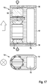
- FIG 17 12 shows an alternative embodiment of the E-axis module 10. Identical elements with respect to FIG Figures 1 to 16 are provided with the same reference numerals and are not explained in more detail.
- the gear arrangement 52 of the E-axis module 10 is designed with a coaxial planetary gear.
Landscapes
- Engineering & Computer Science (AREA)
- Power Engineering (AREA)
- Transportation (AREA)
- Mechanical Engineering (AREA)
- Chemical & Material Sciences (AREA)
- Combustion & Propulsion (AREA)
- Microelectronics & Electronic Packaging (AREA)
- Life Sciences & Earth Sciences (AREA)
- Sustainable Development (AREA)
- Sustainable Energy (AREA)
- Physics & Mathematics (AREA)
- Thermal Sciences (AREA)
- Motor Or Generator Frames (AREA)
Applications Claiming Priority (1)
| Application Number | Priority Date | Filing Date | Title |
|---|---|---|---|
| DE102021210793.1A DE102021210793A1 (de) | 2021-09-28 | 2021-09-28 | Systemgehäuse eines E-Achsen-Moduls |
Publications (2)
| Publication Number | Publication Date |
|---|---|
| EP4155111A1 true EP4155111A1 (fr) | 2023-03-29 |
| EP4155111B1 EP4155111B1 (fr) | 2024-06-05 |
Family
ID=83283284
Family Applications (1)
| Application Number | Title | Priority Date | Filing Date |
|---|---|---|---|
| EP22195153.6A Active EP4155111B1 (fr) | 2021-09-28 | 2022-09-12 | Boîtier de système d'un module d'axe électrique |
Country Status (2)
| Country | Link |
|---|---|
| EP (1) | EP4155111B1 (fr) |
| DE (1) | DE102021210793A1 (fr) |
Citations (6)
| Publication number | Priority date | Publication date | Assignee | Title |
|---|---|---|---|---|
| DE102010041589A1 (de) * | 2010-09-29 | 2012-03-29 | Robert Bosch Gmbh | Gehäuseelement zur Aufnahme einer Leistungselektronik einer Elektromaschine, Gehäuse für eine Elektromaschine, Werkzeug zur Herstellung eines Gehäuseelementes sowie Verfahren zur Herstellung eines Gehäuses für eine Elektromaschine |
| DE102014223909A1 (de) * | 2014-11-24 | 2016-05-25 | Lenze Drives Gmbh | Motorsystem |
| CN106911228A (zh) * | 2015-12-22 | 2017-06-30 | 大陆汽车投资(上海)有限公司 | 电动汽车用集成驱动装置 |
| WO2019051823A1 (fr) * | 2017-09-18 | 2019-03-21 | Robert Bosch Gmbh | Ensemble moteur électrique et onduleur |
| EP3488514A1 (fr) * | 2016-07-20 | 2019-05-29 | LG Electronics Inc. -1- | Boîtier pour moteur électrique |
| DE102019105479A1 (de) * | 2019-03-05 | 2020-09-10 | Avl Software And Functions Gmbh | Elektrische Maschine mit integrierter Leistungselektronik |
-
2021
- 2021-09-28 DE DE102021210793.1A patent/DE102021210793A1/de active Pending
-
2022
- 2022-09-12 EP EP22195153.6A patent/EP4155111B1/fr active Active
Patent Citations (6)
| Publication number | Priority date | Publication date | Assignee | Title |
|---|---|---|---|---|
| DE102010041589A1 (de) * | 2010-09-29 | 2012-03-29 | Robert Bosch Gmbh | Gehäuseelement zur Aufnahme einer Leistungselektronik einer Elektromaschine, Gehäuse für eine Elektromaschine, Werkzeug zur Herstellung eines Gehäuseelementes sowie Verfahren zur Herstellung eines Gehäuses für eine Elektromaschine |
| DE102014223909A1 (de) * | 2014-11-24 | 2016-05-25 | Lenze Drives Gmbh | Motorsystem |
| CN106911228A (zh) * | 2015-12-22 | 2017-06-30 | 大陆汽车投资(上海)有限公司 | 电动汽车用集成驱动装置 |
| EP3488514A1 (fr) * | 2016-07-20 | 2019-05-29 | LG Electronics Inc. -1- | Boîtier pour moteur électrique |
| WO2019051823A1 (fr) * | 2017-09-18 | 2019-03-21 | Robert Bosch Gmbh | Ensemble moteur électrique et onduleur |
| DE102019105479A1 (de) * | 2019-03-05 | 2020-09-10 | Avl Software And Functions Gmbh | Elektrische Maschine mit integrierter Leistungselektronik |
Also Published As
| Publication number | Publication date |
|---|---|
| EP4155111B1 (fr) | 2024-06-05 |
| DE102021210793A1 (de) | 2023-03-30 |
Similar Documents
| Publication | Publication Date | Title |
|---|---|---|
| EP2087258A1 (fr) | Entraînement linéaire par moteur électrique | |
| EP2780200B1 (fr) | Boîtier et kit pour dispositif de commande | |
| EP2626566B1 (fr) | Moteur électrique | |
| DE102017208754A1 (de) | Batteriesystem für ein Elektrofahrzeug | |
| DE102010034520A1 (de) | Träger für ein Steuergerät eines Kraftfahrzeuges, Steuergerät und Kraftfahrzeug | |
| DE2532772A1 (de) | Plattenspeicher-laufwerkeinheit | |
| DE102015207127A1 (de) | Verriegelungs-Struktur zwischen einem Element, das zu lagern ist und einem Lagerungs-Körper | |
| EP3557654A1 (fr) | Dispositif de montage d'un véhicule automobile électrique | |
| DE69004551T2 (de) | Schutzgehäuse für elektrische Verteilerschienen. | |
| WO2012059154A2 (fr) | Moteur électrique, jeu de pièces détachées et procédé de fabrication dudit moteur | |
| EP1640543B1 (fr) | Dispositif de propulsion pour un élément de séparation coulissant | |
| EP0240916B1 (fr) | Matériel d'installation domestique pour conduits de câbles | |
| DE102021214776A1 (de) | E-Achsen-Modul eines elektrischen Fahrzeugs | |
| DE102013021670A1 (de) | Hochvoltbatterie, Kühlkörper dafür und ein Kraftfahrzeug mit einer Hochvoltbatterie | |
| EP4155111B1 (fr) | Boîtier de système d'un module d'axe électrique | |
| DE102022108833B3 (de) | Batterieeinrichtung zur geführten Kühlung von Batteriezellen und einer Stromschiene und Verfahren zum Betrieb einer Batterieeinrichtung zur geführten Kühlung von Batteriezellen und einer Stromschiene | |
| DE102020202749A1 (de) | Systemgehäuse für ein Antriebssystem | |
| DE102008027757A1 (de) | Umrichter-Einbaugerät | |
| DE3735734C2 (fr) | ||
| WO2022122358A1 (fr) | Module d'essieu d'entraînement électrique comprenant une machine électrique | |
| DE102014210915A1 (de) | Elektrowerkzeugmaschine | |
| DE102017218753A1 (de) | Modulare Antriebswechselrichter-Anordnung | |
| DE102014215892A1 (de) | Kühldeckel zum Kühlen von Leistungsendstufenmodulen, Leistungselektronik mit dem Kühldeckel und Hybridmodul mit der Leistungselektronik | |
| DE102019109693A1 (de) | Antriebseinheit mit einer elektrischen Maschine und mit einer Steuereinheit | |
| DE102018128977B4 (de) | Traktionsbatterie-Anordnung für ein Elektrofahrzeug und Verfahren für die Montage einer derartigen Traktionsbatterie-Anordnung |
Legal Events
| Date | Code | Title | Description |
|---|---|---|---|
| PUAI | Public reference made under article 153(3) epc to a published international application that has entered the european phase |
Free format text: ORIGINAL CODE: 0009012 |
|
| STAA | Information on the status of an ep patent application or granted ep patent |
Free format text: STATUS: THE APPLICATION HAS BEEN PUBLISHED |
|
| AK | Designated contracting states |
Kind code of ref document: A1 Designated state(s): AL AT BE BG CH CY CZ DE DK EE ES FI FR GB GR HR HU IE IS IT LI LT LU LV MC MK MT NL NO PL PT RO RS SE SI SK SM TR |
|
| STAA | Information on the status of an ep patent application or granted ep patent |
Free format text: STATUS: REQUEST FOR EXAMINATION WAS MADE |
|
| 17P | Request for examination filed |
Effective date: 20230929 |
|
| RBV | Designated contracting states (corrected) |
Designated state(s): AL AT BE BG CH CY CZ DE DK EE ES FI FR GB GR HR HU IE IS IT LI LT LU LV MC MK MT NL NO PL PT RO RS SE SI SK SM TR |
|
| GRAP | Despatch of communication of intention to grant a patent |
Free format text: ORIGINAL CODE: EPIDOSNIGR1 |
|
| STAA | Information on the status of an ep patent application or granted ep patent |
Free format text: STATUS: GRANT OF PATENT IS INTENDED |
|
| INTG | Intention to grant announced |
Effective date: 20240315 |
|
| GRAS | Grant fee paid |
Free format text: ORIGINAL CODE: EPIDOSNIGR3 |
|
| GRAA | (expected) grant |
Free format text: ORIGINAL CODE: 0009210 |
|
| STAA | Information on the status of an ep patent application or granted ep patent |
Free format text: STATUS: THE PATENT HAS BEEN GRANTED |
|
| AK | Designated contracting states |
Kind code of ref document: B1 Designated state(s): AL AT BE BG CH CY CZ DE DK EE ES FI FR GB GR HR HU IE IS IT LI LT LU LV MC MK MT NL NO PL PT RO RS SE SI SK SM TR |
|
| REG | Reference to a national code |
Ref country code: CH Ref legal event code: EP |
|
| REG | Reference to a national code |
Ref country code: DE Ref legal event code: R096 Ref document number: 502022000990 Country of ref document: DE |
|
| REG | Reference to a national code |
Ref country code: IE Ref legal event code: FG4D Free format text: LANGUAGE OF EP DOCUMENT: GERMAN |
|
| REG | Reference to a national code |
Ref country code: LT Ref legal event code: MG9D |
|
| PG25 | Lapsed in a contracting state [announced via postgrant information from national office to epo] |
Ref country code: BG Free format text: LAPSE BECAUSE OF FAILURE TO SUBMIT A TRANSLATION OF THE DESCRIPTION OR TO PAY THE FEE WITHIN THE PRESCRIBED TIME-LIMIT Effective date: 20240605 |
|
| REG | Reference to a national code |
Ref country code: NL Ref legal event code: MP Effective date: 20240605 |
|
| PG25 | Lapsed in a contracting state [announced via postgrant information from national office to epo] |
Ref country code: HR Free format text: LAPSE BECAUSE OF FAILURE TO SUBMIT A TRANSLATION OF THE DESCRIPTION OR TO PAY THE FEE WITHIN THE PRESCRIBED TIME-LIMIT Effective date: 20240605 Ref country code: FI Free format text: LAPSE BECAUSE OF FAILURE TO SUBMIT A TRANSLATION OF THE DESCRIPTION OR TO PAY THE FEE WITHIN THE PRESCRIBED TIME-LIMIT Effective date: 20240605 |
|
| PG25 | Lapsed in a contracting state [announced via postgrant information from national office to epo] |
Ref country code: GR Free format text: LAPSE BECAUSE OF FAILURE TO SUBMIT A TRANSLATION OF THE DESCRIPTION OR TO PAY THE FEE WITHIN THE PRESCRIBED TIME-LIMIT Effective date: 20240906 |
|
| PG25 | Lapsed in a contracting state [announced via postgrant information from national office to epo] |
Ref country code: ES Free format text: LAPSE BECAUSE OF FAILURE TO SUBMIT A TRANSLATION OF THE DESCRIPTION OR TO PAY THE FEE WITHIN THE PRESCRIBED TIME-LIMIT Effective date: 20240605 |
|
| PG25 | Lapsed in a contracting state [announced via postgrant information from national office to epo] |
Ref country code: LV Free format text: LAPSE BECAUSE OF FAILURE TO SUBMIT A TRANSLATION OF THE DESCRIPTION OR TO PAY THE FEE WITHIN THE PRESCRIBED TIME-LIMIT Effective date: 20240605 |
|
| PG25 | Lapsed in a contracting state [announced via postgrant information from national office to epo] |
Ref country code: NO Free format text: LAPSE BECAUSE OF FAILURE TO SUBMIT A TRANSLATION OF THE DESCRIPTION OR TO PAY THE FEE WITHIN THE PRESCRIBED TIME-LIMIT Effective date: 20240905 Ref country code: LV Free format text: LAPSE BECAUSE OF FAILURE TO SUBMIT A TRANSLATION OF THE DESCRIPTION OR TO PAY THE FEE WITHIN THE PRESCRIBED TIME-LIMIT Effective date: 20240605 Ref country code: HR Free format text: LAPSE BECAUSE OF FAILURE TO SUBMIT A TRANSLATION OF THE DESCRIPTION OR TO PAY THE FEE WITHIN THE PRESCRIBED TIME-LIMIT Effective date: 20240605 Ref country code: GR Free format text: LAPSE BECAUSE OF FAILURE TO SUBMIT A TRANSLATION OF THE DESCRIPTION OR TO PAY THE FEE WITHIN THE PRESCRIBED TIME-LIMIT Effective date: 20240906 Ref country code: FI Free format text: LAPSE BECAUSE OF FAILURE TO SUBMIT A TRANSLATION OF THE DESCRIPTION OR TO PAY THE FEE WITHIN THE PRESCRIBED TIME-LIMIT Effective date: 20240605 Ref country code: ES Free format text: LAPSE BECAUSE OF FAILURE TO SUBMIT A TRANSLATION OF THE DESCRIPTION OR TO PAY THE FEE WITHIN THE PRESCRIBED TIME-LIMIT Effective date: 20240605 Ref country code: BG Free format text: LAPSE BECAUSE OF FAILURE TO SUBMIT A TRANSLATION OF THE DESCRIPTION OR TO PAY THE FEE WITHIN THE PRESCRIBED TIME-LIMIT Effective date: 20240605 Ref country code: RS Free format text: LAPSE BECAUSE OF FAILURE TO SUBMIT A TRANSLATION OF THE DESCRIPTION OR TO PAY THE FEE WITHIN THE PRESCRIBED TIME-LIMIT Effective date: 20240905 |
|
| PG25 | Lapsed in a contracting state [announced via postgrant information from national office to epo] |
Ref country code: NL Free format text: LAPSE BECAUSE OF FAILURE TO SUBMIT A TRANSLATION OF THE DESCRIPTION OR TO PAY THE FEE WITHIN THE PRESCRIBED TIME-LIMIT Effective date: 20240605 |
|
| PG25 | Lapsed in a contracting state [announced via postgrant information from national office to epo] |
Ref country code: NL Free format text: LAPSE BECAUSE OF FAILURE TO SUBMIT A TRANSLATION OF THE DESCRIPTION OR TO PAY THE FEE WITHIN THE PRESCRIBED TIME-LIMIT Effective date: 20240605 |
|
| PG25 | Lapsed in a contracting state [announced via postgrant information from national office to epo] |
Ref country code: PT Free format text: LAPSE BECAUSE OF FAILURE TO SUBMIT A TRANSLATION OF THE DESCRIPTION OR TO PAY THE FEE WITHIN THE PRESCRIBED TIME-LIMIT Effective date: 20241007 |
|
| PG25 | Lapsed in a contracting state [announced via postgrant information from national office to epo] |
Ref country code: PT Free format text: LAPSE BECAUSE OF FAILURE TO SUBMIT A TRANSLATION OF THE DESCRIPTION OR TO PAY THE FEE WITHIN THE PRESCRIBED TIME-LIMIT Effective date: 20241007 |
|
| PG25 | Lapsed in a contracting state [announced via postgrant information from national office to epo] |
Ref country code: PL Free format text: LAPSE BECAUSE OF FAILURE TO SUBMIT A TRANSLATION OF THE DESCRIPTION OR TO PAY THE FEE WITHIN THE PRESCRIBED TIME-LIMIT Effective date: 20240605 |
|
| PG25 | Lapsed in a contracting state [announced via postgrant information from national office to epo] |
Ref country code: EE Free format text: LAPSE BECAUSE OF FAILURE TO SUBMIT A TRANSLATION OF THE DESCRIPTION OR TO PAY THE FEE WITHIN THE PRESCRIBED TIME-LIMIT Effective date: 20240605 |
|
| PG25 | Lapsed in a contracting state [announced via postgrant information from national office to epo] |
Ref country code: IS Free format text: LAPSE BECAUSE OF FAILURE TO SUBMIT A TRANSLATION OF THE DESCRIPTION OR TO PAY THE FEE WITHIN THE PRESCRIBED TIME-LIMIT Effective date: 20241005 |
|
| PG25 | Lapsed in a contracting state [announced via postgrant information from national office to epo] |
Ref country code: CZ Free format text: LAPSE BECAUSE OF FAILURE TO SUBMIT A TRANSLATION OF THE DESCRIPTION OR TO PAY THE FEE WITHIN THE PRESCRIBED TIME-LIMIT Effective date: 20240605 |
|
| PG25 | Lapsed in a contracting state [announced via postgrant information from national office to epo] |
Ref country code: SK Free format text: LAPSE BECAUSE OF FAILURE TO SUBMIT A TRANSLATION OF THE DESCRIPTION OR TO PAY THE FEE WITHIN THE PRESCRIBED TIME-LIMIT Effective date: 20240605 Ref country code: RO Free format text: LAPSE BECAUSE OF FAILURE TO SUBMIT A TRANSLATION OF THE DESCRIPTION OR TO PAY THE FEE WITHIN THE PRESCRIBED TIME-LIMIT Effective date: 20240605 |
|
| PG25 | Lapsed in a contracting state [announced via postgrant information from national office to epo] |
Ref country code: SM Free format text: LAPSE BECAUSE OF FAILURE TO SUBMIT A TRANSLATION OF THE DESCRIPTION OR TO PAY THE FEE WITHIN THE PRESCRIBED TIME-LIMIT Effective date: 20240605 |
|
| PG25 | Lapsed in a contracting state [announced via postgrant information from national office to epo] |
Ref country code: SM Free format text: LAPSE BECAUSE OF FAILURE TO SUBMIT A TRANSLATION OF THE DESCRIPTION OR TO PAY THE FEE WITHIN THE PRESCRIBED TIME-LIMIT Effective date: 20240605 Ref country code: SK Free format text: LAPSE BECAUSE OF FAILURE TO SUBMIT A TRANSLATION OF THE DESCRIPTION OR TO PAY THE FEE WITHIN THE PRESCRIBED TIME-LIMIT Effective date: 20240605 Ref country code: RO Free format text: LAPSE BECAUSE OF FAILURE TO SUBMIT A TRANSLATION OF THE DESCRIPTION OR TO PAY THE FEE WITHIN THE PRESCRIBED TIME-LIMIT Effective date: 20240605 Ref country code: PL Free format text: LAPSE BECAUSE OF FAILURE TO SUBMIT A TRANSLATION OF THE DESCRIPTION OR TO PAY THE FEE WITHIN THE PRESCRIBED TIME-LIMIT Effective date: 20240605 Ref country code: IS Free format text: LAPSE BECAUSE OF FAILURE TO SUBMIT A TRANSLATION OF THE DESCRIPTION OR TO PAY THE FEE WITHIN THE PRESCRIBED TIME-LIMIT Effective date: 20241005 Ref country code: EE Free format text: LAPSE BECAUSE OF FAILURE TO SUBMIT A TRANSLATION OF THE DESCRIPTION OR TO PAY THE FEE WITHIN THE PRESCRIBED TIME-LIMIT Effective date: 20240605 Ref country code: CZ Free format text: LAPSE BECAUSE OF FAILURE TO SUBMIT A TRANSLATION OF THE DESCRIPTION OR TO PAY THE FEE WITHIN THE PRESCRIBED TIME-LIMIT Effective date: 20240605 |
|
| PG25 | Lapsed in a contracting state [announced via postgrant information from national office to epo] |
Ref country code: IT Free format text: LAPSE BECAUSE OF FAILURE TO SUBMIT A TRANSLATION OF THE DESCRIPTION OR TO PAY THE FEE WITHIN THE PRESCRIBED TIME-LIMIT Effective date: 20240605 |
|
| REG | Reference to a national code |
Ref country code: DE Ref legal event code: R097 Ref document number: 502022000990 Country of ref document: DE |
|
| PLBE | No opposition filed within time limit |
Free format text: ORIGINAL CODE: 0009261 |
|
| STAA | Information on the status of an ep patent application or granted ep patent |
Free format text: STATUS: NO OPPOSITION FILED WITHIN TIME LIMIT |
|
| PG25 | Lapsed in a contracting state [announced via postgrant information from national office to epo] |
Ref country code: DK Free format text: LAPSE BECAUSE OF FAILURE TO SUBMIT A TRANSLATION OF THE DESCRIPTION OR TO PAY THE FEE WITHIN THE PRESCRIBED TIME-LIMIT Effective date: 20240605 |
|
| PG25 | Lapsed in a contracting state [announced via postgrant information from national office to epo] |
Ref country code: MC Free format text: LAPSE BECAUSE OF FAILURE TO SUBMIT A TRANSLATION OF THE DESCRIPTION OR TO PAY THE FEE WITHIN THE PRESCRIBED TIME-LIMIT Effective date: 20240605 |
|
| 26N | No opposition filed |
Effective date: 20250306 |
|
| PG25 | Lapsed in a contracting state [announced via postgrant information from national office to epo] |
Ref country code: LU Free format text: LAPSE BECAUSE OF NON-PAYMENT OF DUE FEES Effective date: 20240912 |
|
| REG | Reference to a national code |
Ref country code: BE Ref legal event code: MM Effective date: 20240930 |
|
| PG25 | Lapsed in a contracting state [announced via postgrant information from national office to epo] |
Ref country code: BE Free format text: LAPSE BECAUSE OF NON-PAYMENT OF DUE FEES Effective date: 20240930 |
|
| PG25 | Lapsed in a contracting state [announced via postgrant information from national office to epo] |
Ref country code: IE Free format text: LAPSE BECAUSE OF NON-PAYMENT OF DUE FEES Effective date: 20240912 |
|
| PG25 | Lapsed in a contracting state [announced via postgrant information from national office to epo] |
Ref country code: SE Free format text: LAPSE BECAUSE OF FAILURE TO SUBMIT A TRANSLATION OF THE DESCRIPTION OR TO PAY THE FEE WITHIN THE PRESCRIBED TIME-LIMIT Effective date: 20240605 |
|
| PGFP | Annual fee paid to national office [announced via postgrant information from national office to epo] |
Ref country code: AT Payment date: 20251020 Year of fee payment: 4 Ref country code: FR Payment date: 20250922 Year of fee payment: 4 |
|
| PGFP | Annual fee paid to national office [announced via postgrant information from national office to epo] |
Ref country code: DE Payment date: 20251121 Year of fee payment: 4 |
|
| PG25 | Lapsed in a contracting state [announced via postgrant information from national office to epo] |
Ref country code: CY Free format text: LAPSE BECAUSE OF FAILURE TO SUBMIT A TRANSLATION OF THE DESCRIPTION OR TO PAY THE FEE WITHIN THE PRESCRIBED TIME-LIMIT; INVALID AB INITIO Effective date: 20220912 |
|
| PG25 | Lapsed in a contracting state [announced via postgrant information from national office to epo] |
Ref country code: HU Free format text: LAPSE BECAUSE OF FAILURE TO SUBMIT A TRANSLATION OF THE DESCRIPTION OR TO PAY THE FEE WITHIN THE PRESCRIBED TIME-LIMIT; INVALID AB INITIO Effective date: 20220912 |