EP4155145A1 - Procédé et dispositif de conduite pour véhicule hybride, et véhicule - Google Patents
Procédé et dispositif de conduite pour véhicule hybride, et véhicule Download PDFInfo
- Publication number
- EP4155145A1 EP4155145A1 EP21863735.3A EP21863735A EP4155145A1 EP 4155145 A1 EP4155145 A1 EP 4155145A1 EP 21863735 A EP21863735 A EP 21863735A EP 4155145 A1 EP4155145 A1 EP 4155145A1
- Authority
- EP
- European Patent Office
- Prior art keywords
- drive mode
- torque
- hybrid electric
- vehicle
- electric vehicle
- Prior art date
- Legal status (The legal status is an assumption and is not a legal conclusion. Google has not performed a legal analysis and makes no representation as to the accuracy of the status listed.)
- Pending
Links
Images


Classifications
-
- B—PERFORMING OPERATIONS; TRANSPORTING
- B60—VEHICLES IN GENERAL
- B60W—CONJOINT CONTROL OF VEHICLE SUB-UNITS OF DIFFERENT TYPE OR DIFFERENT FUNCTION; CONTROL SYSTEMS SPECIALLY ADAPTED FOR HYBRID VEHICLES; ROAD VEHICLE DRIVE CONTROL SYSTEMS FOR PURPOSES NOT RELATED TO THE CONTROL OF A PARTICULAR SUB-UNIT
- B60W30/00—Purposes of road vehicle drive control systems not related to the control of a particular sub-unit, e.g. of systems using conjoint control of vehicle sub-units
- B60W30/18—Propelling the vehicle
- B60W30/182—Selecting between different operative modes, e.g. comfort and performance modes
-
- B—PERFORMING OPERATIONS; TRANSPORTING
- B60—VEHICLES IN GENERAL
- B60W—CONJOINT CONTROL OF VEHICLE SUB-UNITS OF DIFFERENT TYPE OR DIFFERENT FUNCTION; CONTROL SYSTEMS SPECIALLY ADAPTED FOR HYBRID VEHICLES; ROAD VEHICLE DRIVE CONTROL SYSTEMS FOR PURPOSES NOT RELATED TO THE CONTROL OF A PARTICULAR SUB-UNIT
- B60W20/00—Control systems specially adapted for hybrid vehicles
- B60W20/10—Controlling the power contribution of each of the prime movers to meet required power demand
-
- B—PERFORMING OPERATIONS; TRANSPORTING
- B60—VEHICLES IN GENERAL
- B60K—ARRANGEMENT OR MOUNTING OF PROPULSION UNITS OR OF TRANSMISSIONS IN VEHICLES; ARRANGEMENT OR MOUNTING OF PLURAL DIVERSE PRIME-MOVERS IN VEHICLES; AUXILIARY DRIVES FOR VEHICLES; INSTRUMENTATION OR DASHBOARDS FOR VEHICLES; ARRANGEMENTS IN CONNECTION WITH COOLING, AIR INTAKE, GAS EXHAUST OR FUEL SUPPLY OF PROPULSION UNITS IN VEHICLES
- B60K6/00—Arrangement or mounting of plural diverse prime-movers for mutual or common propulsion, e.g. hybrid propulsion systems comprising electric motors and internal combustion engines
- B60K6/20—Arrangement or mounting of plural diverse prime-movers for mutual or common propulsion, e.g. hybrid propulsion systems comprising electric motors and internal combustion engines the prime-movers consisting of electric motors and internal combustion engines, e.g. HEVs
- B60K6/42—Arrangement or mounting of plural diverse prime-movers for mutual or common propulsion, e.g. hybrid propulsion systems comprising electric motors and internal combustion engines the prime-movers consisting of electric motors and internal combustion engines, e.g. HEVs characterised by the architecture of the hybrid electric vehicle
- B60K6/44—Series-parallel type
- B60K6/442—Series-parallel switching type
-
- B—PERFORMING OPERATIONS; TRANSPORTING
- B60—VEHICLES IN GENERAL
- B60W—CONJOINT CONTROL OF VEHICLE SUB-UNITS OF DIFFERENT TYPE OR DIFFERENT FUNCTION; CONTROL SYSTEMS SPECIALLY ADAPTED FOR HYBRID VEHICLES; ROAD VEHICLE DRIVE CONTROL SYSTEMS FOR PURPOSES NOT RELATED TO THE CONTROL OF A PARTICULAR SUB-UNIT
- B60W10/00—Conjoint control of vehicle sub-units of different type or different function
- B60W10/04—Conjoint control of vehicle sub-units of different type or different function including control of propulsion units
- B60W10/06—Conjoint control of vehicle sub-units of different type or different function including control of propulsion units including control of combustion engines
-
- B—PERFORMING OPERATIONS; TRANSPORTING
- B60—VEHICLES IN GENERAL
- B60W—CONJOINT CONTROL OF VEHICLE SUB-UNITS OF DIFFERENT TYPE OR DIFFERENT FUNCTION; CONTROL SYSTEMS SPECIALLY ADAPTED FOR HYBRID VEHICLES; ROAD VEHICLE DRIVE CONTROL SYSTEMS FOR PURPOSES NOT RELATED TO THE CONTROL OF A PARTICULAR SUB-UNIT
- B60W10/00—Conjoint control of vehicle sub-units of different type or different function
- B60W10/04—Conjoint control of vehicle sub-units of different type or different function including control of propulsion units
- B60W10/08—Conjoint control of vehicle sub-units of different type or different function including control of propulsion units including control of electric propulsion units, e.g. motors or generators
-
- B—PERFORMING OPERATIONS; TRANSPORTING
- B60—VEHICLES IN GENERAL
- B60W—CONJOINT CONTROL OF VEHICLE SUB-UNITS OF DIFFERENT TYPE OR DIFFERENT FUNCTION; CONTROL SYSTEMS SPECIALLY ADAPTED FOR HYBRID VEHICLES; ROAD VEHICLE DRIVE CONTROL SYSTEMS FOR PURPOSES NOT RELATED TO THE CONTROL OF A PARTICULAR SUB-UNIT
- B60W20/00—Control systems specially adapted for hybrid vehicles
- B60W20/10—Controlling the power contribution of each of the prime movers to meet required power demand
- B60W20/11—Controlling the power contribution of each of the prime movers to meet required power demand using model predictive control [MPC] strategies, i.e. control methods based on models predicting performance
-
- B—PERFORMING OPERATIONS; TRANSPORTING
- B60—VEHICLES IN GENERAL
- B60W—CONJOINT CONTROL OF VEHICLE SUB-UNITS OF DIFFERENT TYPE OR DIFFERENT FUNCTION; CONTROL SYSTEMS SPECIALLY ADAPTED FOR HYBRID VEHICLES; ROAD VEHICLE DRIVE CONTROL SYSTEMS FOR PURPOSES NOT RELATED TO THE CONTROL OF A PARTICULAR SUB-UNIT
- B60W20/00—Control systems specially adapted for hybrid vehicles
- B60W20/10—Controlling the power contribution of each of the prime movers to meet required power demand
- B60W20/15—Control strategies specially adapted for achieving a particular effect
-
- B—PERFORMING OPERATIONS; TRANSPORTING
- B60—VEHICLES IN GENERAL
- B60W—CONJOINT CONTROL OF VEHICLE SUB-UNITS OF DIFFERENT TYPE OR DIFFERENT FUNCTION; CONTROL SYSTEMS SPECIALLY ADAPTED FOR HYBRID VEHICLES; ROAD VEHICLE DRIVE CONTROL SYSTEMS FOR PURPOSES NOT RELATED TO THE CONTROL OF A PARTICULAR SUB-UNIT
- B60W20/00—Control systems specially adapted for hybrid vehicles
- B60W20/20—Control strategies involving selection of hybrid configuration, e.g. selection between series or parallel configuration
-
- B—PERFORMING OPERATIONS; TRANSPORTING
- B60—VEHICLES IN GENERAL
- B60W—CONJOINT CONTROL OF VEHICLE SUB-UNITS OF DIFFERENT TYPE OR DIFFERENT FUNCTION; CONTROL SYSTEMS SPECIALLY ADAPTED FOR HYBRID VEHICLES; ROAD VEHICLE DRIVE CONTROL SYSTEMS FOR PURPOSES NOT RELATED TO THE CONTROL OF A PARTICULAR SUB-UNIT
- B60W30/00—Purposes of road vehicle drive control systems not related to the control of a particular sub-unit, e.g. of systems using conjoint control of vehicle sub-units
- B60W30/18—Propelling the vehicle
-
- B—PERFORMING OPERATIONS; TRANSPORTING
- B60—VEHICLES IN GENERAL
- B60W—CONJOINT CONTROL OF VEHICLE SUB-UNITS OF DIFFERENT TYPE OR DIFFERENT FUNCTION; CONTROL SYSTEMS SPECIALLY ADAPTED FOR HYBRID VEHICLES; ROAD VEHICLE DRIVE CONTROL SYSTEMS FOR PURPOSES NOT RELATED TO THE CONTROL OF A PARTICULAR SUB-UNIT
- B60W2510/00—Input parameters relating to a particular sub-units
- B60W2510/06—Combustion engines, Gas turbines
- B60W2510/0638—Engine speed
-
- B—PERFORMING OPERATIONS; TRANSPORTING
- B60—VEHICLES IN GENERAL
- B60W—CONJOINT CONTROL OF VEHICLE SUB-UNITS OF DIFFERENT TYPE OR DIFFERENT FUNCTION; CONTROL SYSTEMS SPECIALLY ADAPTED FOR HYBRID VEHICLES; ROAD VEHICLE DRIVE CONTROL SYSTEMS FOR PURPOSES NOT RELATED TO THE CONTROL OF A PARTICULAR SUB-UNIT
- B60W2510/00—Input parameters relating to a particular sub-units
- B60W2510/06—Combustion engines, Gas turbines
- B60W2510/0657—Engine torque
-
- B—PERFORMING OPERATIONS; TRANSPORTING
- B60—VEHICLES IN GENERAL
- B60W—CONJOINT CONTROL OF VEHICLE SUB-UNITS OF DIFFERENT TYPE OR DIFFERENT FUNCTION; CONTROL SYSTEMS SPECIALLY ADAPTED FOR HYBRID VEHICLES; ROAD VEHICLE DRIVE CONTROL SYSTEMS FOR PURPOSES NOT RELATED TO THE CONTROL OF A PARTICULAR SUB-UNIT
- B60W2540/00—Input parameters relating to occupants
- B60W2540/10—Accelerator pedal position
- B60W2540/106—Rate of change
-
- B—PERFORMING OPERATIONS; TRANSPORTING
- B60—VEHICLES IN GENERAL
- B60W—CONJOINT CONTROL OF VEHICLE SUB-UNITS OF DIFFERENT TYPE OR DIFFERENT FUNCTION; CONTROL SYSTEMS SPECIALLY ADAPTED FOR HYBRID VEHICLES; ROAD VEHICLE DRIVE CONTROL SYSTEMS FOR PURPOSES NOT RELATED TO THE CONTROL OF A PARTICULAR SUB-UNIT
- B60W2710/00—Output or target parameters relating to a particular sub-units
- B60W2710/06—Combustion engines, Gas turbines
- B60W2710/0666—Engine torque
-
- B—PERFORMING OPERATIONS; TRANSPORTING
- B60—VEHICLES IN GENERAL
- B60W—CONJOINT CONTROL OF VEHICLE SUB-UNITS OF DIFFERENT TYPE OR DIFFERENT FUNCTION; CONTROL SYSTEMS SPECIALLY ADAPTED FOR HYBRID VEHICLES; ROAD VEHICLE DRIVE CONTROL SYSTEMS FOR PURPOSES NOT RELATED TO THE CONTROL OF A PARTICULAR SUB-UNIT
- B60W2710/00—Output or target parameters relating to a particular sub-units
- B60W2710/08—Electric propulsion units
- B60W2710/083—Torque
-
- Y—GENERAL TAGGING OF NEW TECHNOLOGICAL DEVELOPMENTS; GENERAL TAGGING OF CROSS-SECTIONAL TECHNOLOGIES SPANNING OVER SEVERAL SECTIONS OF THE IPC; TECHNICAL SUBJECTS COVERED BY FORMER USPC CROSS-REFERENCE ART COLLECTIONS [XRACs] AND DIGESTS
- Y02—TECHNOLOGIES OR APPLICATIONS FOR MITIGATION OR ADAPTATION AGAINST CLIMATE CHANGE
- Y02T—CLIMATE CHANGE MITIGATION TECHNOLOGIES RELATED TO TRANSPORTATION
- Y02T10/00—Road transport of goods or passengers
- Y02T10/60—Other road transportation technologies with climate change mitigation effect
- Y02T10/62—Hybrid vehicles
Definitions
- the present disclosure relates to the field of hybrid electric vehicles, and more particularly to a method and a device for driving a hybrid electric vehicle, and a vehicle.
- the architecture of maximizing the efficiency of the vehicle there is a system architecture that divides the vehicle drive mode into a parallel drive mode, a series drive mode, and a pure electric drive mode.
- the engine works to supply power to the drive motor
- the maximum torque that the vehicle can provide is the maximum torque that the drive motor can provide
- the engine directly provides power for the vehicle and drives the vehicle in parallel with the drive motor.
- the maximum torque that the vehicle can provide is the maximum torque that the drive motor can provide and the maximum torque that the engine can provide. That is, the maximum torque that the vehicle can provide when driven by the parallel drive mode is the maximum torque that the vehicle can provide.
- the vehicle control unit determines the best drive mode of the vehicle according to the power demand of the driver and the state of vehicle for driving the vehicle.
- the vehicle In the related driving field, when the torque demand of the vehicle is within the working economic zone corresponding to the current engine speed, the vehicle is driven by the parallel drive mode; in addition, when the torque demand of the vehicle is higher than the maximum torque that the drive motor can provide at the current engine speed, the vehicle is also driven in the parallel drive mode.
- a main object of the present disclosure is to provide a method and a device for driving a hybrid electric vehicle, and a vehicle, in order to solve the problem in the art that when the torque demand of the vehicle when driving fluctuates in the economic zone corresponding to the current speed or near the maximum torque that the drive motor can provide, frequent switching between series and parallel modes will occur.
- the hybrid electric vehicle includes a drive motor and an engine, and the method includes:
- the step of determining an engine economic zone and a power assistance reserve zone corresponding to the current speed includes:
- the method further includes: switching to, if after the vehicle demand torque continues to increase to the maximum value of the power assistance reserve zone, and the vehicle demand torque does not increase to a maximum torque that the drive motor is able to provide within a preset time, a series drive mode to drive the hybrid electric vehicle when the hybrid electric vehicle is in the parallel drive mode and a torque provided by the parallel drive mode under a current drive mode is greater than a maximum torque provided by the drive motor.
- the method further includes: controlling, if the vehicle demand torque is greater than a maximum value of the engine economic zone and the vehicle demand torque is less than a maximum value of the power assistance reserved zone, the engine to provide a torque less than the maximum value of the engine economic zone, and controlling the drive motor to provide a torque equal to a difference between the vehicle demand torque and a torque provided by the engine when the hybrid electric vehicle is in the parallel drive mode, if the vehicle demand torque is greater than a maximum value of the engine economic zone and the vehicle demand torque is less than a maximum value of the power assistance reserved zone.
- the hybrid electric vehicle includes drive modes, and the drive modes include a series drive mode and a parallel drive mode
- the method further includes: sending, if the vehicle demand torque is greater than a minimum value of the engine economic zone, and the vehicle demand torque is less than a maximum value of the power assistance reserved zone, a mode switching command to switch the hybrid electric vehicle from the series drive mode to the parallel drive mode when the hybrid electric vehicle is in the series drive mode.
- the hybrid electric vehicle includes drive modes, and the drive modes include a series drive mode and a parallel drive mode
- the method further includes: sending, if the vehicle demand torque is greater than the maximum torque that the drive motor is able to provide, a mode switching command to switch the hybrid electric vehicle to the parallel drive mode when the hybrid electric vehicle is in the series drive mode and a torque that the parallel drive mode is able to provide is greater than a maximum torque that the drive motor is able to provide under a current drive mode.
- the present disclosure further provides a device for driving a hybrid electric vehicle.
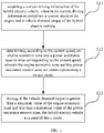
- the hybrid electric vehicle includes a drive motor and an engine, and the device includes: an acquisition module, a processing module, a first control module, and/or a second control module.
- the acquisition module is configured for acquiring a current driving information of the hybrid electric vehicle, wherein the current driving information comprises a current speed of the engine and a vehicle demand torque of the hybrid electric vehicle;
- the a processing module is configured for determining, according to the current speed, an engine economic zone and a power assistance reserve zone corresponding to the current speed, wherein the engine economic zone and the power assistance reserve zone are zones representing a torque range;
- the first control module is configured for driving the hybrid electric vehicle in a parallel drive mode when the vehicle demand torque is greater than a minimum value of the engine economic zone and less than a maximum value of the power assistance reserve zone; and/or the second control module is configured for maintaining, if the vehicle demand torque continues to increase to the maximum value of the power assistance reserve zone, the hybrid electric vehicle being driven in
- the second control module is further configured for: maintaining, if the demand torque of the vehicle is greater than the maximum value of the power assistance reserve zone and less than a maximum torque that the drive motor can provide, the parallel drive mode when the hybrid electric vehicle is in the parallel drive mode and the vehicle demand torque continues to increase, and the torque that the parallel drive mode is able to provide is greater than a maximum torque that the drive motor is able to provide under a current drive mode.
- the second control module is further configured for: sending, if the vehicle demand torque does not increase to a maximum torque that the drive motor is able to provide within a preset time after the vehicle demand torque continues to increase to the maximum value of the power assistance reserve zone, a mode switching command to switch to a series drive mode to drive the hybrid electric vehicle when the hybrid electric vehicle is in the parallel drive mode and a torque provided by the parallel drive mode under a current drive mode is greater than a maximum torque provided by the drive motor.
- the second control module is further configured for: controlling, if the vehicle demand torque is greater than a maximum value of the engine economic zone and the vehicle demand torque is less than a maximum value of the power assistance reserved zone, the engine to provide a torque less than the maximum value of the engine economic zone, and controlling the drive motor to provide a torque equal to a difference between the vehicle demand torque and a torque provided by the engine when the hybrid electric vehicle is in the parallel drive mode.
- the hybrid electric vehicle includes drive modes, and the drive modes include a series drive mode and a parallel drive mode
- the second control module is further configured for: sending, if the vehicle demand torque is greater than a minimum value of the engine economic zone, and the vehicle demand torque is less than a maximum value of the power assistance reserved zone, a mode switching command to switch the hybrid electric vehicle from the series drive mode to the parallel drive mode when the hybrid electric vehicle is in the series drive mode.
- the hybrid electric vehicle includes drive modes, and the drive modes include a series drive mode and a parallel drive mode
- the second control module is further configured for: sending, if the vehicle demand torque is greater than the maximum torque that the drive motor is able to provide, a mode switching command to switch the hybrid electric vehicle to the parallel drive mode when the hybrid electric vehicle is in the series drive mode and a torque that the parallel drive mode is able to provide is greater than a maximum torque that the drive motor is able to provide under a current drive mode.
- the present disclosure further provides a hybrid electric vehicle.
- the hybrid electric vehicle includes a drive motor, an engine, and a drive device connected with the drive motor and the engine; the drive device is configured for executing the method for driving the hybrid electric vehicle as described above.
- the present disclosure further provides a computing processing device.
- the computing processing device includes:
- the present disclosure further provides a computer program.
- the computer program computer-readable codes when the computer-readable codes are executed by the computing processing device, the computing processing device executes the method for driving a hybrid electric vehicle as described above.
- the present disclosure further provides a computer-readable storage medium, and a computer program as described above is stored therein.
- the system architecture of the hybrid vehicle can be a system architecture aimed at maximizing the efficiency of the vehicle, and divides the vehicle drive mode into a parallel drive mode, a series drive mode and a pure electric drive mode.
- the vehicle control unit determines the best drive mode of the vehicle according to the power demand of the driver and the state of vehicle for driving the vehicle. For example, when the torque demand of the vehicle is within the working economic zone corresponding to the current engine speed, the vehicle is driven by the parallel drive mode; in addition, when the maximum torque that can be provided by the parallel drive mode under the current drive mode is greater than the maximum torque that can be provided by the drive motor, and the torque demand of the vehicle is higher than the maximum torque that can be provided by the drive motor under the current engine speed, the parallel drive mode is switched to drive the vehicle.
- the drive modes are divided. In some drive modes, considering the engine operating efficiency or battery power, the maximum torque can be provided by the parallel drive mode may be less than the maximum torque can be provided by the drive motor, that is, the maximum torque can be provided by the serial drive mode. In the embodiments provided by the present disclosure, the drive mode generally considered is the drive mode in which the maximum torque can be provided by the parallel drive mode is greater than the maximum torque can be provided by the drive motor.
- the embodiment of the present disclosure provides a method for driving a hybrid electric vehicle.
- the method can be applied to the VCU of the hybrid electric vehicle, as shown in FIG. 1 .
- the method includes:
- step S 12 the optimal operating point of the engine corresponding to the current speed can be acquired according to the current speed, and the engine economic zone can be determined according to the optimal operating point of the engine.
- the optimal operating point of the engine can be calculated by the R&D personnel in advance according to the inherent performance of the engine and stored in the vehicle control unit.
- the optimal operating point of the engine is positively related to the current speed and is in the engine economic zone.
- the power assistance reserve zone can be determined according to the engine economic zone, where the minimum value of the power assistance reserve zone is the maximum value of the engine economic zone, and the vehicle torque corresponding to the maximum value of the power assistance reserve zone is less than the maximum torque that the drive motor can provide.
- the vehicle control unit When the vehicle control unit detects that the vehicle demand torque acquired in step S11 is greater than the minimum value of the engine economic zone determined in step S12, and the vehicle demand torque is less than the maximum value of the power assistance reserve zone, the vehicle control unit controls the vehicle to maintain driving in the parallel drive mode.
- the power assistance reserve zone is additionally set above the engine economic zone, so that when the vehicle demand torque is greater than the minimum value of the engine economic zone and less than the maximum value of the power assistance reserve zone, the hybrid electric vehicle can be driven in a parallel drive mode, which increases the range of vehicle demand torque for driving the hybrid electric vehicle in a parallel drive mode, and the problem of frequent mode switching caused by the fluctuation of the vehicle demand torque near the maximum value of the engine economic zone is avoided.
- the engine when the hybrid electric vehicle is in the parallel drive mode, if the vehicle demand torque is greater than the maximum value of the engine economic zone, and the vehicle demand torque is less than the maximum value of the power assistance reserve zone, the engine is controlled to provide a torque that is less than the maximum value of the engine economic zone.
- the torque provided by the engine at this time can be equal to the torque corresponding to the optimal operating point of the engine, and the drive motor can be controlled to provide a torque equal to the difference between the vehicle demand torque and the torque provided by the engine. At this time, it can ensure that the vehicle demand torque is greater than the maximum value of the engine economic zone, and the economic benefits of the vehicle and the driving ability of the vehicle are guaranteed.
- FIG. 2 shows a method for driving hybrid electric vehicles provided by another embodiment of the present disclosure, which is used to solve the problem that the vehicle torque continues to increase and the mode switches too frequently before reaching the maximum torque that the drive battery can provide.
- the method can be applied to the VCU of the hybrid electric vehicle. As shown in FIG. 2 , the method includes the following steps:
- the vehicle demand torque is predicted.
- the hybrid electric vehicle is maintained to be driven in the parallel drive mode during the period when the vehicle demand torque continues to increase from the maximum value of the power assistance reserve zone to the maximum torque that the drive motor can provide, and the frequency of switching drive modes of the hybrid electric vehicle is reduced.
- FIG. 3 is an exemplary comparison diagram between a vehicle demand torque and the vehicle drive mode in the case of adopting the method provided by an embodiment of the present disclosure.
- a curve 4 represents a mapping relationship curve between the engine optimal operating point (the operating point value is the output torque value) and the engine speed.
- the range between a curve 3 and a curve 5 represents the engine economic zone corresponding to the engine speed, that is, the value of each engine speed corresponds to an engine economic zone, such as engine economic zone A shown in FIG. 3 .
- the engine economic zone always includes the engine optimal operating point.
- the engine optimal operating point can be located in the center of the engine economic zone.
- the range between a curve 2 and a curve 3 represents the power assistance reserve zone corresponding to the engine speed, that is, the value of each engine speed corresponds to a power assistance reserve zone, such as power assistance reserve zone B shown in FIG. 3 .
- a curve 2 represented by dotted line is an example of the mapping relationship between the vehicle demand power and engine speed.
- the vehicle when the vehicle demand power is between the minimum value of the engine economic zone and the maximum value of the power assistance reserve zone, the vehicle always maintains the parallel drive mode. That is, when the vehicle is currently in the parallel drive mode, when the engine speed is W1 and W3 (the corresponding vehicle demand power increases to the maximum value of the engine economic zone), or in the case that the engine speed is W2 (the corresponding vehicle demand power decreases to the maximum value in the engine economic zone), the vehicle maintains the parallel drive mode unchanged, and mode switching will not occur. Only when the engine speed is W4 (the vehicle demand power increases to the maximum value in the power assistance reserve zone), the vehicle will be controlled to switch from the parallel drive mode to the series drive mode.
- the range of the vehicle demand torque in parallel drive mode is between the minimum value of the engine economic zone and the maximum value of the power assistance reserve (for example, the range C shown in FIG. 3 ).
- the torque range of the vehicle driven by parallel drive mode is increased, and the number of mode switching is reduced.
- FIG. 4 is another exemplary comparison diagram between the vehicle demand torque and the vehicle drive mode in the case of adopting the method provided by the embodiments of the present disclosure.
- a curve 1 represents the mapping relationship curve between the maximum torque that the hybrid electric vehicle can provide in the parallel drive mode and the engine speed, that is, the sum value of the maximum torque that the engine can provide and the maximum torque that the drive motor can provide.
- a curve 3 represents the mapping relationship curve between the maximum torque that can be provided by the hybrid electric vehicle in series drive mode and the engine speed, that is, the maximum torque that can be provided by the drive motor.
- a curve 6 represents the mapping relationship curve between the optimal operating point of the engine (the operating point value is the output torque value) and the engine speed.
- the range between a curve 5 and a curve 7 represents the engine economic zone corresponding to the engine speed, that is, the value of each engine speed corresponds to an engine economic zone, such as engine economic zone A shown in FIG. 4 .
- the engine economic zone always includes the engine optimal operating point.
- the engine optimal operating point can be located in the center of the engine economic zone.
- the range between a curve 4 and a curve 5 represents the power assistance reserve zone corresponding to the engine speed, that is, the value of each engine speed corresponds to a power assistance reserve zone, such as the power assistance reserve zone B shown in FIG. 4 .
- a curve 2 represented by dotted line is an example of the mapping relationship between the vehicle demand power and engine speed. Different from the curve 2 shown in FIG. 3 , the mapping relationship curve represents that the vehicle demand power continues to increase with the increase of engine speed.
- the engine speed is W1
- the vehicle demand torque is increase to the minimum value of the engine economic zone
- the vehicle drive mode is switched to the parallel drive mode.
- the vehicle demand power is between the maximum value of the power assistance reserve zone at the current speed and the maximum torque that can be provided by the vehicle in series drive mode, the vehicle always maintains the parallel drive mode.
- the vehicle demand torque maintains in the parallel drive mode when the vehicle demand torque is between the maximum value of the power assistance reserve zone and the maximum torque that can be provided by the vehicle in the series drive mode, thus avoiding frequent mode switching before the vehicle demand torque is increased to the maximum torque that can be provided by the vehicle in the series drive mode, and the number of mode switching is reduced.
- the embodiment of the present disclosure further provides a device 50 for driving a hybrid electric vehicle, which is used to implement the steps of the method for driving provided by the above method embodiments.
- the device 50 can realize the vehicle control unit on the hybrid electric vehicle in the way of software, hardware or a combination of both.
- the vehicle control unit can be used for the hybrid electric vehicle including the drive modes including the pure electric drive mode, the series drive mode, and the parallel drive mode, as shown in FIG. 5 , the device 50 includes:
- the power assistance reserve zone is additionally set above the engine economic zone, so that when the vehicle demand torque is greater than the minimum value of the engine economic zone and less than the maximum value of the power assistance reserve zone, the hybrid electric vehicle can be driven in a parallel drive mode, which increases the range of vehicle demand torque for driving the hybrid electric vehicle in a parallel drive mode, and the problem of frequent mode switching caused by the fluctuation of the vehicle demand torque near the maximum value of the engine economic zone is avoided.
- the hybrid electric vehicle is maintained to be driven in the parallel drive mode during the period when the vehicle demand torque continues to increase from the maximum value of the power assistance reserve zone to the maximum torque that the drive motor can provide, and the frequency of switching drive modes of the hybrid electric vehicle is reduced.
- the processing module 52 is configured for determining the engine economic zone and the power assistance reserve zone corresponding to the current speed, specifically: acquiring an optimal operating point of the engine corresponding to the current speed according to the current speed, and determining the engine economic zone according to the optimal operating point of the engine, in which the optimal operating point of the engine is positively related to the current speed and is within the engine economic zone; and determining the power assistance reserve zone according to the engine economic zone, and a minimum value of the power assistance reserve zone is a maximum value of the engine economic zone, and a vehicle torque corresponding to the maximum value of the power assistance reserve zone is less than a maximum torque that the drive motor is able to provide.
- the second control module 55 is configured for switching to, if after the vehicle demand torque continues to increase to the maximum value of the power assistance reserve zone, and the vehicle demand torque does not increase to a maximum torque that the drive motor is able to provide within a preset time, a series drive mode to drive the hybrid electric vehicle when the hybrid electric vehicle is in the parallel drive mode and a torque provided by the parallel drive mode under a current drive mode is greater than a maximum torque provided by the drive motor.
- the parallel drive mode is then abandoned, so as to reasonably distribute the vehicle power, save fuel and ensure that the vehicle power demand is met.
- the second control module 55 is further configured for controlling, if the vehicle demand torque is greater than a maximum value of the engine economic zone and the vehicle demand torque is less than a maximum value of the power assistance reserved zone, the engine to provide a torque less than the maximum value of the engine economic zone, for example, it can be the torque corresponding to the optimal operating point of the engine; and controlling the drive motor to provide a torque equal to a difference between the vehicle demand torque and a torque provided by the engine when the hybrid electric vehicle is in the parallel drive mode, if the vehicle demand torque is greater than a maximum value of the engine economic zone and the vehicle demand torque is less than a maximum value of the power assistance reserved zone. At this time, the vehicle engine is still working in the engine economic zone, which ensures the efficient operation of the engine and enables the power provided by the vehicle to meet the normal driving of the vehicle.
- the second control module 55 is further configured for sending, if the vehicle demand torque is greater than a minimum value of the engine economic zone, and the vehicle demand torque is less than a maximum value of the power assistance reserved zone, a mode switching command to switch the hybrid electric vehicle from the series drive mode or the pure electric drive mode to the parallel drive mode when the hybrid electric vehicle is in the series drive mode.
- the second control module 55 is further configured for sending, if the vehicle demand torque is greater than the maximum torque that the drive motor is able to provide, a mode switching command to switch the hybrid electric vehicle to the parallel drive mode when the hybrid electric vehicle is in the series drive mode, so as to ensure that the vehicle can provide enough torque for normal driving of the vehicle.
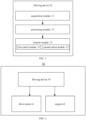
- the embodiment of the present disclosure further provides a hybrid vehicle 60, which includes a drive motor 61, an engine 62, and a driving device 50 connected with the drive motor and the engine, which is used to implement the method for driving the hybrid electric vehicle.
- a hybrid vehicle 60 which includes a drive motor 61, an engine 62, and a driving device 50 connected with the drive motor and the engine, which is used to implement the method for driving the hybrid electric vehicle.
- the hybrid electric vehicle further includes other components.
- FIG. 6 only shows the parts related to the embodiments of the present disclosure, and other necessary vehicle components are not shown in details.
- the computing processing device includes:
- the present disclosure further provides a computer program.
- the computer program computer-readable codes when the computer-readable codes are executed by the computing processing device, the computing processing device executes the method for driving a hybrid electric vehicle as described above.
- the present disclosure further provides a computer-readable storage medium, and a computer program as described above is stored therein.
- FIG. 7 provides a structural schematic diagram of a computing processing device for the embodiment of the present disclosure.
- the computing processing apparatus typically includes a processor 710 and a computer program product or computer-readable medium in the form of a memory 730.
- the memory 730 may be an electronic memory such as flash memory, electrically erasable programmable read only memory (EEPROM), EPROM, hard disk, or ROM.
- the memory 730 has a storage space 750 of program code 751 for executing any of the method steps described above.
- the storage space 750 for program code may include each program code 751 for implementing various steps in the above method. These program codes can be read from or written into one or more computer program products.
- These computer program products include program code carriers such as hard disk, compact disc (CD), memory card, or floppy disk.
- a computer program product is usually a portable or fixed storage unit as shown in FIG. 8 .
- the storage unit may have storage segments, storage spaces, and the like arranged similarly to the memory 730 in the server of FIG. 7 .
- the program code may be compressed in an appropriate form, for example.
- the storage unit includes computer readable code 751 ', that is, codes that can be read by a processor such as 710, when the codes are run by a server, which causes the server to perform the steps in the method described above.
- first and second are only used for description purposes and cannot be understood as indicating or implying relative importance or implicitly indicating the number of indicated technical features.
- the features defined as “first” and “second” can explicitly or implicitly include at least one such feature.
- “multiple” means at least two, such as two, three, etc., unless otherwise specifically defined.
- a "computer-readable medium” may be any device that may include, store, communicate, propagate, or transmit programs for use by or in conjunction with instruction execution system, device, or apparatus.
- computer-readable media include the following: an electrical connector (electronic device) with one or more wiring, a portable computer disk box (magnetic device), a random access memory (RAM), a read-only memory (ROM), an erasable and editable read-only memory (EPROM or flash memory), an optical fiber device, and a portable optical disk read-only memory (CDROM).
- the computer-readable medium can even be a paper or other suitable medium on which the program can be printed, because the program can be acquired electronically, for example, by optical scanning of the paper or other medium, then editing, interpreting, or processing in other suitable ways when necessary, and then stored in a computer memory.
- the various parts of the present disclosure may be implemented in hardware, software, firm ware, or a combination thereof.
- a plurality of steps or methods may be implemented with software or firmware stored in memory and executed by a suitable instruction execution system.
- the hardware implementation is the same as that in another embodiment, it can be realized by any one of the following technologies known in the art or their combination: discrete logic circuit with logic gate circuit for realizing logic function on data signal, special integrated circuit with suitable combined logic gate circuit, programmable gate array (PGA), field programmable gate array (FPGA), etc.
- each functional unit in each embodiment of the present disclosure can be integrated in a processing module, or each unit can exist physically independently, or two or more units can be integrated in a module.
- the above integrated modules can be implemented in the form of hardware or software function modules. If the integrated module is realized in the form of a software functional module and sold or used as an independent product, it can also be stored in a computer readable storage medium.
- the storage medium mentioned above can be read-only memory, disk or optical disk.
Landscapes
- Engineering & Computer Science (AREA)
- Chemical & Material Sciences (AREA)
- Combustion & Propulsion (AREA)
- Transportation (AREA)
- Mechanical Engineering (AREA)
- Automation & Control Theory (AREA)
- Electric Propulsion And Braking For Vehicles (AREA)
- Hybrid Electric Vehicles (AREA)
Applications Claiming Priority (2)
| Application Number | Priority Date | Filing Date | Title |
|---|---|---|---|
| CN202010929961.6A CN112124297B (zh) | 2020-09-07 | 2020-09-07 | 混合动力车辆的驱动方法、装置和车辆 |
| PCT/CN2021/116796 WO2022048673A1 (fr) | 2020-09-07 | 2021-09-06 | Procédé et dispositif de conduite pour véhicule hybride, et véhicule |
Publications (2)
| Publication Number | Publication Date |
|---|---|
| EP4155145A1 true EP4155145A1 (fr) | 2023-03-29 |
| EP4155145A4 EP4155145A4 (fr) | 2023-11-29 |
Family
ID=73848139
Family Applications (1)
| Application Number | Title | Priority Date | Filing Date |
|---|---|---|---|
| EP21863735.3A Pending EP4155145A4 (fr) | 2020-09-07 | 2021-09-06 | Procédé et dispositif de conduite pour véhicule hybride, et véhicule |
Country Status (4)
| Country | Link |
|---|---|
| US (1) | US12371002B2 (fr) |
| EP (1) | EP4155145A4 (fr) |
| CN (1) | CN112124297B (fr) |
| WO (1) | WO2022048673A1 (fr) |
Families Citing this family (6)
| Publication number | Priority date | Publication date | Assignee | Title |
|---|---|---|---|---|
| CN112124297B (zh) * | 2020-09-07 | 2022-04-29 | 长城汽车股份有限公司 | 混合动力车辆的驱动方法、装置和车辆 |
| US11981320B2 (en) * | 2020-10-28 | 2024-05-14 | Nissan Motor Co., Ltd. | Method for controlling hybrid vehicle and hybrid vehicle |
| CN112977396B (zh) * | 2021-03-18 | 2022-04-22 | 中国第一汽车股份有限公司 | 混合动力汽车发电扭矩分配方法及混合动力汽车 |
| CN113460030B (zh) * | 2021-08-05 | 2024-04-05 | 奇瑞商用车(安徽)有限公司 | 混联式混合动力扭矩分配方法 |
| CN115107738B (zh) * | 2022-01-07 | 2025-07-18 | 长城汽车股份有限公司 | 混动车辆的切换控制方法、整车控制器、混动车辆 |
| CN114802194B (zh) * | 2022-05-31 | 2025-08-01 | 中国第一汽车股份有限公司 | 混合动力车辆串并联模式的控制方法及电子装置 |
Family Cites Families (22)
| Publication number | Priority date | Publication date | Assignee | Title |
|---|---|---|---|---|
| JP2007261442A (ja) * | 2006-03-29 | 2007-10-11 | Nissan Motor Co Ltd | ハイブリッド車両の運転モード遷移制御装置 |
| CN103189258B (zh) * | 2010-11-04 | 2016-05-11 | 丰田自动车株式会社 | 车辆用混合动力驱动装置 |
| JP6274386B2 (ja) * | 2013-01-09 | 2018-02-07 | 三菱自動車工業株式会社 | ハイブリッド車のエンジン運転制御装置 |
| US9045136B2 (en) * | 2013-02-08 | 2015-06-02 | Efficient Drivetrains, Inc. | Systems and methods for implementing dynamic operating modes and control policies for hybrid electric vehicles |
| CN104417544B (zh) * | 2013-09-09 | 2017-08-22 | 比亚迪股份有限公司 | 混合动力汽车的控制系统和控制方法 |
| CN105620467B (zh) * | 2014-10-31 | 2018-08-14 | 比亚迪股份有限公司 | 混合动力车辆及混合动力车辆的驱动控制方法 |
| CN105730433B (zh) * | 2014-12-10 | 2018-08-03 | 北汽福田汽车股份有限公司 | 一种混合动力车模式切换方法和系统 |
| CN104590248B (zh) * | 2015-01-04 | 2017-04-05 | 郑州宇通客车股份有限公司 | 一种基于串并联混合动力系统的控制方法 |
| EP3305615B1 (fr) * | 2015-06-03 | 2019-09-25 | Nissan Motor Co., Ltd. | Dispositif de commande de transition de mode pour véhicule hybride |
| CN105035089A (zh) * | 2015-08-07 | 2015-11-11 | 厦门金龙联合汽车工业有限公司 | 一种混联混合动力系统串并联切换控制算法 |
| CN107487317A (zh) * | 2016-07-15 | 2017-12-19 | 宝沃汽车(中国)有限公司 | 用于并联式混合动力车辆的扭矩分配方法和装置 |
| MX373515B (es) * | 2016-07-15 | 2020-04-21 | Nissan Motor | Método de control de momento de torsión y dispositivo de control de momento de torsión. |
| KR102659047B1 (ko) * | 2016-12-16 | 2024-04-19 | 현대자동차주식회사 | 하이브리드 자동차 및 그를 위한 모드 전환 제어 방법 |
| JP2018154230A (ja) * | 2017-03-17 | 2018-10-04 | 株式会社豊田中央研究所 | ハイブリッド車両の制御システム |
| CN109383486A (zh) * | 2017-08-04 | 2019-02-26 | 郑州宇通客车股份有限公司 | 混合动力汽车扭矩控制方法和混合动力汽车动力系统 |
| CN109458252B (zh) * | 2018-11-02 | 2020-06-26 | 潍柴动力股份有限公司 | 一种发动机冷却系统的控制方法、控制装置及发动机 |
| CN111439252B (zh) * | 2018-12-27 | 2022-06-14 | 比亚迪股份有限公司 | 混合动力车辆及扭矩控制方法、存储介质和变速箱控制器 |
| CN110217221B (zh) * | 2019-06-25 | 2021-02-19 | 四川阿尔特新能源汽车有限公司 | 巡航控制方法、装置、整车控制器、车辆及可读存储介质 |
| CN111483327B (zh) * | 2019-07-16 | 2021-11-02 | 长城汽车股份有限公司 | 电机控制方法、装置、设备及计算机可读存储介质 |
| CN110949368B (zh) | 2019-12-06 | 2021-08-03 | 中国第一汽车股份有限公司 | 混合动力车辆的控制方法、装置、存储介质及车辆 |
| CN111267833B (zh) * | 2020-02-19 | 2022-04-05 | 义乌吉利动力总成有限公司 | 一种混合动力系统的并联模式换挡方法、系统及汽车 |
| CN112124297B (zh) * | 2020-09-07 | 2022-04-29 | 长城汽车股份有限公司 | 混合动力车辆的驱动方法、装置和车辆 |
-
2020
- 2020-09-07 CN CN202010929961.6A patent/CN112124297B/zh active Active
-
2021
- 2021-09-06 EP EP21863735.3A patent/EP4155145A4/fr active Pending
- 2021-09-06 WO PCT/CN2021/116796 patent/WO2022048673A1/fr not_active Ceased
- 2021-09-06 US US18/010,339 patent/US12371002B2/en active Active
Also Published As
| Publication number | Publication date |
|---|---|
| CN112124297B (zh) | 2022-04-29 |
| US12371002B2 (en) | 2025-07-29 |
| CN112124297A (zh) | 2020-12-25 |
| EP4155145A4 (fr) | 2023-11-29 |
| WO2022048673A1 (fr) | 2022-03-10 |
| US20230249668A1 (en) | 2023-08-10 |
Similar Documents
| Publication | Publication Date | Title |
|---|---|---|
| EP4155145A1 (fr) | Procédé et dispositif de conduite pour véhicule hybride, et véhicule | |
| KR102948888B1 (ko) | 하이브리드 차량을 위한 제어 방법, 및 차량 제어 유닛 | |
| US20230173950A1 (en) | Fuel cell vehicle energy management method and system, and vehicle | |
| US12280673B2 (en) | Method for controlling vehicle mounted game, computational processing device, and non-transitory computer readable storage medium | |
| CN112092650B (zh) | 增程式电动汽车及其控制方法、装置和存储介质 | |
| US9007013B2 (en) | Inverter control method and system for eco-friendly vehicle | |
| EP4491473A1 (fr) | Procédé et appareil de commande de véhicule hybride à quatre roues motrices, véhicule et support d'enregistrement | |
| EP4155121B1 (fr) | Procédé de commande de pile à combustible de véhicule, dispositif, programme, support et véhicule | |
| US20210240512A1 (en) | Vehicle control device, vehicle control method and storage medium storing vehicle control program | |
| US20140103843A1 (en) | Inverter control method and system for eco-friendly vehicle | |
| EP4159563A1 (fr) | Procédé et appareil de commande de couple de véhicule hybride, support de stockage et dispositif électronique | |
| EP4464565A1 (fr) | Procédé de commande de commutation pour véhicule hybride, dispositif de commande de véhicule et véhicule hybride | |
| EP4507069A1 (fr) | Procédé et système de commande d'autochauffage de batterie, et véhicule électrique | |
| US12567616B2 (en) | Method for controlling heating of battery pack, computational processing device, and non-transitory computer readable storage medium | |
| US12570170B2 (en) | Direct current converter, controlling method, and vehicle | |
| CN109739145B (zh) | 整车控制器控制方法及装置 | |
| US11979053B2 (en) | System, vehicle, discharge method, and program | |
| JP7721933B2 (ja) | システム設定支援装置およびシステム設定支援プログラム | |
| KR102927727B1 (ko) | 모터 구동 제어 장치 및 방법 | |
| CN114274842B (zh) | 电动汽车能量源控制方法、装置、电动汽车及存储介质 | |
| US8028297B2 (en) | Nonstop program system and a method of continuously running programs by switching between program sides | |
| EP4664719A2 (fr) | Système de charge et procédé de charge | |
| CN114764226B (zh) | 应用于便携式设备的电源管理系统及方法 | |
| JP7406538B2 (ja) | 装置システム | |
| CN117553418A (zh) | 电机驱动装置及其控制方法、电子设备和存储介质 |
Legal Events
| Date | Code | Title | Description |
|---|---|---|---|
| STAA | Information on the status of an ep patent application or granted ep patent |
Free format text: STATUS: THE INTERNATIONAL PUBLICATION HAS BEEN MADE |
|
| PUAI | Public reference made under article 153(3) epc to a published international application that has entered the european phase |
Free format text: ORIGINAL CODE: 0009012 |
|
| STAA | Information on the status of an ep patent application or granted ep patent |
Free format text: STATUS: REQUEST FOR EXAMINATION WAS MADE |
|
| 17P | Request for examination filed |
Effective date: 20221223 |
|
| AK | Designated contracting states |
Kind code of ref document: A1 Designated state(s): AL AT BE BG CH CY CZ DE DK EE ES FI FR GB GR HR HU IE IS IT LI LT LU LV MC MK MT NL NO PL PT RO RS SE SI SK SM TR |
|
| P01 | Opt-out of the competence of the unified patent court (upc) registered |
Effective date: 20230530 |
|
| A4 | Supplementary search report drawn up and despatched |
Effective date: 20231027 |
|
| RIC1 | Information provided on ipc code assigned before grant |
Ipc: B60W 10/06 20060101ALI20231023BHEP Ipc: B60W 30/18 20120101ALI20231023BHEP Ipc: B60W 20/20 20160101ALI20231023BHEP Ipc: B60W 20/10 20160101AFI20231023BHEP |
|
| DAV | Request for validation of the european patent (deleted) | ||
| DAX | Request for extension of the european patent (deleted) | ||
| STAA | Information on the status of an ep patent application or granted ep patent |
Free format text: STATUS: EXAMINATION IS IN PROGRESS |
|
| 17Q | First examination report despatched |
Effective date: 20250509 |
|
| GRAP | Despatch of communication of intention to grant a patent |
Free format text: ORIGINAL CODE: EPIDOSNIGR1 |
|
| STAA | Information on the status of an ep patent application or granted ep patent |
Free format text: STATUS: GRANT OF PATENT IS INTENDED |