EP4155155A1 - Procédé et dispositif d'affichage de processus de stationnement et véhicule - Google Patents
Procédé et dispositif d'affichage de processus de stationnement et véhicule Download PDFInfo
- Publication number
- EP4155155A1 EP4155155A1 EP21876979.2A EP21876979A EP4155155A1 EP 4155155 A1 EP4155155 A1 EP 4155155A1 EP 21876979 A EP21876979 A EP 21876979A EP 4155155 A1 EP4155155 A1 EP 4155155A1
- Authority
- EP
- European Patent Office
- Prior art keywords
- display region
- vehicle
- center
- image
- origin
- Prior art date
- Legal status (The legal status is an assumption and is not a legal conclusion. Google has not performed a legal analysis and makes no representation as to the accuracy of the status listed.)
- Pending
Links
Images




Classifications
-
- B—PERFORMING OPERATIONS; TRANSPORTING
- B60—VEHICLES IN GENERAL
- B60R—VEHICLES, VEHICLE FITTINGS, OR VEHICLE PARTS, NOT OTHERWISE PROVIDED FOR
- B60R1/00—Optical viewing arrangements; Real-time viewing arrangements for drivers or passengers using optical image capturing systems, e.g. cameras or video systems specially adapted for use in or on vehicles
- B60R1/20—Real-time viewing arrangements for drivers or passengers using optical image capturing systems, e.g. cameras or video systems specially adapted for use in or on vehicles
- B60R1/22—Real-time viewing arrangements for drivers or passengers using optical image capturing systems, e.g. cameras or video systems specially adapted for use in or on vehicles for viewing an area outside the vehicle, e.g. the exterior of the vehicle
- B60R1/23—Real-time viewing arrangements for drivers or passengers using optical image capturing systems, e.g. cameras or video systems specially adapted for use in or on vehicles for viewing an area outside the vehicle, e.g. the exterior of the vehicle with a predetermined field of view
- B60R1/27—Real-time viewing arrangements for drivers or passengers using optical image capturing systems, e.g. cameras or video systems specially adapted for use in or on vehicles for viewing an area outside the vehicle, e.g. the exterior of the vehicle with a predetermined field of view providing all-round vision, e.g. using omnidirectional cameras
-
- B—PERFORMING OPERATIONS; TRANSPORTING
- B60—VEHICLES IN GENERAL
- B60W—CONJOINT CONTROL OF VEHICLE SUB-UNITS OF DIFFERENT TYPE OR DIFFERENT FUNCTION; CONTROL SYSTEMS SPECIALLY ADAPTED FOR HYBRID VEHICLES; ROAD VEHICLE DRIVE CONTROL SYSTEMS FOR PURPOSES NOT RELATED TO THE CONTROL OF A PARTICULAR SUB-UNIT
- B60W50/00—Details of control systems for road vehicle drive control not related to the control of a particular sub-unit, e.g. process diagnostic or vehicle driver interfaces
- B60W50/08—Interaction between the driver and the control system
- B60W50/14—Means for informing the driver, warning the driver or prompting a driver intervention
-
- B—PERFORMING OPERATIONS; TRANSPORTING
- B60—VEHICLES IN GENERAL
- B60W—CONJOINT CONTROL OF VEHICLE SUB-UNITS OF DIFFERENT TYPE OR DIFFERENT FUNCTION; CONTROL SYSTEMS SPECIALLY ADAPTED FOR HYBRID VEHICLES; ROAD VEHICLE DRIVE CONTROL SYSTEMS FOR PURPOSES NOT RELATED TO THE CONTROL OF A PARTICULAR SUB-UNIT
- B60W30/00—Purposes of road vehicle drive control systems not related to the control of a particular sub-unit, e.g. of systems using conjoint control of vehicle sub-units
- B60W30/06—Automatic manoeuvring for parking
-
- B—PERFORMING OPERATIONS; TRANSPORTING
- B62—LAND VEHICLES FOR TRAVELLING OTHERWISE THAN ON RAILS
- B62D—MOTOR VEHICLES; TRAILERS
- B62D15/00—Steering not otherwise provided for
- B62D15/02—Steering position indicators ; Steering position determination; Steering aids
- B62D15/027—Parking aids, e.g. instruction means
-
- G—PHYSICS
- G06—COMPUTING OR CALCULATING; COUNTING
- G06V—IMAGE OR VIDEO RECOGNITION OR UNDERSTANDING
- G06V20/00—Scenes; Scene-specific elements
- G06V20/50—Context or environment of the image
- G06V20/56—Context or environment of the image exterior to a vehicle by using sensors mounted on the vehicle
- G06V20/58—Recognition of moving objects or obstacles, e.g. vehicles or pedestrians; Recognition of traffic objects, e.g. traffic signs, traffic lights or roads
- G06V20/586—Recognition of moving objects or obstacles, e.g. vehicles or pedestrians; Recognition of traffic objects, e.g. traffic signs, traffic lights or roads of parking space
-
- B—PERFORMING OPERATIONS; TRANSPORTING
- B60—VEHICLES IN GENERAL
- B60R—VEHICLES, VEHICLE FITTINGS, OR VEHICLE PARTS, NOT OTHERWISE PROVIDED FOR
- B60R2300/00—Details of viewing arrangements using cameras and displays, specially adapted for use in a vehicle
- B60R2300/10—Details of viewing arrangements using cameras and displays, specially adapted for use in a vehicle characterised by the type of camera system used
-
- B—PERFORMING OPERATIONS; TRANSPORTING
- B60—VEHICLES IN GENERAL
- B60R—VEHICLES, VEHICLE FITTINGS, OR VEHICLE PARTS, NOT OTHERWISE PROVIDED FOR
- B60R2300/00—Details of viewing arrangements using cameras and displays, specially adapted for use in a vehicle
- B60R2300/20—Details of viewing arrangements using cameras and displays, specially adapted for use in a vehicle characterised by the type of display used
-
- B—PERFORMING OPERATIONS; TRANSPORTING
- B60—VEHICLES IN GENERAL
- B60R—VEHICLES, VEHICLE FITTINGS, OR VEHICLE PARTS, NOT OTHERWISE PROVIDED FOR
- B60R2300/00—Details of viewing arrangements using cameras and displays, specially adapted for use in a vehicle
- B60R2300/80—Details of viewing arrangements using cameras and displays, specially adapted for use in a vehicle characterised by the intended use of the viewing arrangement
- B60R2300/806—Details of viewing arrangements using cameras and displays, specially adapted for use in a vehicle characterised by the intended use of the viewing arrangement for aiding parking
-
- B—PERFORMING OPERATIONS; TRANSPORTING
- B60—VEHICLES IN GENERAL
- B60W—CONJOINT CONTROL OF VEHICLE SUB-UNITS OF DIFFERENT TYPE OR DIFFERENT FUNCTION; CONTROL SYSTEMS SPECIALLY ADAPTED FOR HYBRID VEHICLES; ROAD VEHICLE DRIVE CONTROL SYSTEMS FOR PURPOSES NOT RELATED TO THE CONTROL OF A PARTICULAR SUB-UNIT
- B60W50/00—Details of control systems for road vehicle drive control not related to the control of a particular sub-unit, e.g. process diagnostic or vehicle driver interfaces
- B60W50/08—Interaction between the driver and the control system
- B60W50/14—Means for informing the driver, warning the driver or prompting a driver intervention
- B60W2050/146—Display means
Definitions
- the present disclosure relates to the technical field of automobiles, and more particularly, to a parking process display method and device, and a vehicle.
- the existing automatic parking uses the automatic parking function of a vehicle to park the vehicle in/out of a parking spot according to a parking in/out instruction.
- a parking image shot by a vehicle-mounted camera is displayed via a display window with a fixed field of view, of a display screen of a vehicle-mounted terminal of the vehicle.
- the present disclosure aims at providing a parking process display method and device, and a vehicle.
- a parking process display method applied to a vehicle-mounted terminal of a vehicle wherein the method includes:
- a parking process display device applied to a vehicle-mounted terminal of a vehicle, wherein the device includes:
- a vehicle including a vehicle-mounted terminal, wherein the vehicle further includes the parking process display device.
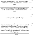
- FIG. 1 shows a flow chart of a parking process display method according to an embodiment of the present disclosure.
- the parking process display method provided according to the embodiment of the present disclosure is applied to a vehicle-mounted terminal of a vehicle.
- Step 101 establishing an image of a scene where the vehicle is located, and the image is established based on a preset coordinate system.
- FIG. 2 shows a structural diagram of a vehicle according to an embodiment of the present disclosure, which includes a vehicle 10, wide-angle sensors 11, and a vehicle-mounted terminal 12.
- a vehicle 10 wide-angle sensors 11
- a vehicle-mounted terminal 12 There may be a plurality of wide-angle sensors 11, a plurality of the wide-angle sensors 11 are disposed on the outer surface of the vehicle 10, and data collected by the wide-angle sensors 11 may be sent to the vehicle-mounted terminal 12.
- four wide-angle sensors 11 may be provided, and the four wide-angle sensors 11 are disposed on four corners of the vehicle 10, respectively.
- the wide-angle sensors 11 are used for collecting image data and are wider in shooting field of view and capable of collecting images of ambient environments of the vehicle 10, and a plurality of the disposed wide-angle sensors 11 may provide real-time images with a three hundred and sixty degrees angle surrounding the vehicle to the vehicle-mounted terminal 12, thereby providing a wider field of view for a driver and eliminating the blind region of the field of view as much as possible.
- FIG. 3 shows a structural block view of a vehicle-mounted terminal according to an embodiment of the present disclosure
- the vehicle-mounted terminal includes a three-dimensional scene establishment module, a two-dimensional scene conversion module, a viewing angle interception module, a movement relationship controller module, and an image display module.
- the three-dimensional scene establishment module may establish a three-dimensional scene image of the scene where the vehicle is located on the basis of environmental information collected by the wide-angle sensors, the three-dimensional scene image may be displayed by the image display module, so as to provide a user perception for a three-dimensional scene.
- a two-dimensional scene establishment module may map the three-dimensional scene image into a planar two-dimensional scene image at the top viewing angle, on the basis of the three-dimensional scene image established by the three-dimensional scene establishment module, and according to a top viewing angle set in a parking scene.
- the movement relationship controller module may collect information of movement parameters such as a speed, a direction, and a trajectory, etc., of the vehicle.
- the viewing angle interception module may control the interception of the parts of regions on the basis of the movement parameters, collected by the movement relationship controller module of the vehicle, and may enable a parking spot to be parked and a vehicle located in the parts of regions at the same time.
- the image display module may display the parts of regions in the two-dimensional scene image selected by the viewing angle interception module, so as to provide a user perception for a parking process.
- the two-dimensional scene establishment module of the vehicle-mounted terminal may map the three-dimensional scene image into the planar two-dimensional scene image at the top viewing angle according to the top viewing angle set in the parking scene, and the two-dimensional scene image may be established on the basis of the preset coordinate system such as a rectangular coordinate system.
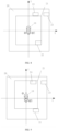
- FIG. 4 shows a structural diagram of a two-dimensional scene image according to an embodiment of the present disclosure, a two-dimensional scene image 20 which is at the top viewing angle and includes a vehicle 10 is established on the basis of the three-dimensional scene image, and reference may be made to the position of each object in the two-dimensional scene image 20.
- Step 102 determining a display region in the image, and displaying the display region, wherein the display region including the vehicle.
- the image may be the two-dimensional scene image or the three-dimensional scene image, which is not limited in the embodiment of the present disclosure.
- the two-dimensional scene image due to the limited field of view of the display of the vehicle-mounted terminal, it may only display parts of regions in the two-dimensional scene image at one time, and therefore, the display region with a preset size in the two-dimensional scene image may be selected by the viewing angle interception module of the vehicle-mounted terminal, and the display region is displayed by the image display module of the vehicle-mounted terminal.
- the size of the display region may be obtained by calculating according to the size or resolution of the display of the vehicle-mounted terminal.
- the selected display region 21 it is necessary for the selected display region 21 to include the vehicle 10 because it involves a parking scene.
- an initial state namely a state as shown in FIG. 4
- the center of the vehicle 10 may overlap with the origin of the XY rectangular coordinate system of the two-dimensional scene image 20, and the center of the display region 21 may also overlap with the origin, in this way, the vehicle-mounted terminal may display the display region 21 with the vehicle 10 as the center in the initial state, so that a user knows about the environmental condition surrounding the vehicle before parking.
- the center of the display region, the center of the coordinate system and the center of the vehicle may also be kept in a preset relative positional relationship, other than overlapping according to practical demands, which is not limited in the embodiment of the present disclosure.
- Step 103 identifying a parking spot in the image.
- the vehicle-mounted terminal may identify all parking spots in the image based on an image feature identification technology.
- the vehicle-mounted terminal may match an image feature of a standard parking spot with an image feature of each region in the image, and determine a region that matches the image feature of the standard parking spot in the image, as the region where the parking spot is located.
- Step 104 when at least parts of regions of a target parking spot and/or of the vehicle are located outside the display region, adjusting a relative position of a center of the display region in the image to an origin of the preset coordinate system, to enable entire regions of the vehicle and the target parking spot to be located in the display region.
- the target parking spot may be a parking spot to be parked in or out in all the parking spots.
- the target parking spot may be voluntarily selected by a user or may be selected by the vehicle-mounted terminal according to an practical strategy. For example, a parking spot closest to the vehicle and in a direction in which the vehicle satisfies a parking-in/out condition is determined as the target parking spot. For example, in FIG.
- the parking spot 23 may be used as the target parking spot according to a selection operation of the user, or the parking spot 22 closest to the vehicle 10 may be automatically determined as the target parking spot.
- FIG. 5 shows a structural diagram of another two-dimensional scene image according to an embodiment of the present disclosure, assuming that the parking spot 22 is the target parking spot, and the vehicle 10 moves in a Y-axis direction, if the center O of the display region 21 is kept to overlap with the center of the vehicle 10 in the movement process of the vehicle 10, the target parking spot 22 may entirely (as shown in FIG. 5 ) or partially move out of the range of the display region 21 in the movement process of the vehicle 10, which causes the loss of the image of the target parking spot 22.
- the vehicle 10 may entirely or partially move out of the range of the display region 21 in the movement process of the vehicle 10, which causes the loss of the image of the vehicle 10.
- the relative position of the center of the display region in the image to the origin of the coordinate system may be adjusted according to the target parking spot in the image and the direction of the vehicle, so that the entire regions of the vehicle and the target parking spot are located in the display region in the parking process, and then, the problem of less satisfying of parking experience caused by the loss of the images of the vehicle and the target parking spot is reduced.
- FIG. 6 shows a structural diagram of another two-dimensional scene image according to an embodiment of the present disclosure
- the center O of the display region 21 may be moved in a direction away from the Y-axis direction to change a positional relationship between the center O of the display region 21 and the origin O' of the coordinate system, so that the vehicle 10 and the target parking spot 22 are located in the display region 21 at the same time, which guarantees the integrity of a parking image in a parking link.
- the embodiment of the present disclosure provides the parking process display method including: establishing an image of a scene where the vehicle is located, and the image is established based on a preset coordinate system; determining a display region in the image, and displaying the display region, wherein the display region including the vehicle; identifying a parking spot in the image; when at least parts of regions of a target parking spot and/or of the vehicle are located outside the display region, adjusting a relative position of a center of the display region in the image to an origin of the preset coordinate system, to enable entire regions of the vehicle and the target parking spot to be located in the display region.
- the display of the vehicle-mounted terminal is limited in display range, in order to guarantee the integrity of the parking image displayed in the display region in the parking process, in the embodiment of the present disclosure, when the images of the target parking spot and/or vehicle in the display region are incomplete, the relative position of the center of the display region to the origin of the coordinate system of the image may be adjusted to change the position of the display region with respect to the image, so that the entire regions of the vehicle and the target parking spot are located in the display region, and then, the probability that the problem of integrity loss of the parking image in the parking process occurs is reduced.
- FIG. 7 shows a flow chart of another parking process display method according to an embodiment of the present disclosure.
- the parking process display method provided according to the embodiment of the present disclosure is applied to a vehicle-mounted terminal of a vehicle.
- another parking process display method is described with a two-dimensional scene image as an example in the embodiment of the present disclosure.
- a vehicle 10 is provided with at least one wide-angle sensor 11.
- Step 201 acquiring environmental information collected by the wide-angle sensor.
- the wide-angle sensors are used for collecting image data and are wider in shooting field of view and capable of collecting environmental information of ambient environments of the vehicle, wherein the environmental information may include point cloud data which is a set of point data, obtained by a measuring instrument, of the outer surface of objects in an environment and is used for establishing a three-dimensional scene image; and a plurality of disposed wide-angle sensors may provide real-time images with a three hundred and sixty degrees angle surrounding the vehicle for the vehicle-mounted terminal, thereby providing a wider field of view for a driver and eliminating the blind region of the field of view as much as possible.
- point cloud data is a set of point data, obtained by a measuring instrument, of the outer surface of objects in an environment and is used for establishing a three-dimensional scene image
- a plurality of disposed wide-angle sensors may provide real-time images with a three hundred and sixty degrees angle surrounding the vehicle for the vehicle-mounted terminal, thereby providing a wider field of view for a driver and eliminating the blind region of the field of view as much as possible.
- Step 202 establishing a three-dimensional scene image of the scene where the vehicle is located according to the environmental information.
- the three-dimensional scene module of the vehicle-mounted terminal may establish the three-dimensional scene image of the scene where the vehicle is located by means of the point cloud data in the environmental information.
- the process of establishing the three-dimensional scene image may be achieved by a fitting operation of the point cloud data and may be assisted by a deep learning model.
- Step 203 mapping the three-dimensional scene image into a two-dimensional scene image with a preset size to obtain the two-dimensional scene image of the scene where the vehicle is located.
- the two-dimensional scene establishment module may map the three-dimensional scene image into a planar two-dimensional scene image at the top viewing angle, on the basis of the three-dimensional scene image established by a three-dimensional scene establishment module and according to a top viewing angle set in a parking scene.
- the parking scene may be defaulted to be displayed at the top viewing angle.
- Step 204 determining a size of the display region according to a size of a display screen of the vehicle-mounted terminal.
- a display of the vehicle-mounted terminal is limited in field of view, and may only display parts of regions in the two-dimensional scene image as the display region at one time, and therefore, the viewing angle interception module may firstly determine the size of the display region according to the size of the display screen of the vehicle-mounted terminal, so that the size of the display region does not exceed the field of view of the display of the vehicle-mounted terminal at least.
- the size of the display region may be obtained by calculating according to the size or resolution of the display of the vehicle-mounted terminal.
- Step 205 determining the display region in the two-dimensional scene image according to the size of the display region, and displaying the display region.
- the specific position of the display region in the two-dimensional scene image may be selected; under a normal circumstance, a parking spot to be parked and the vehicle are enabled to be located in the display region at the same time as much as possible; and under other circumstances, the display region may also be located on a default fixed position in the two-dimensional scene image according to an practical demand.
- Step 206 setting the center of the display region, the center of the vehicle and the origin to overlap in the image.
- the center of the display region is kept to overlap with the center of the vehicle, or the center of the display region is kept to overlap with the origin.
- the center of the vehicle 10 in an initial state (namely a state as shown in FIG. 4 ), the center of the vehicle 10 may overlap with the origin O' of the XY rectangular coordinate system of the two-dimensional scene image 20, and the center O of the display region 21 is set to overlap with the origin O', in this way, the vehicle-mounted terminal may display the display region 21 with the vehicle 10 as the center in the initial state, so that a user knows about the environmental condition surrounding the vehicle before parking.
- the center of the display region may be kept to overlap with the center of the vehicle in the movement process of the vehicle, so that the effect of keeping the vehicle located in the center of the display region is achieved, and it is convenient to get a perception range of the environmental condition surrounding the vehicle as wide as possible.
- the center of the display region is kept to overlap with the center of the vehicle in the movement process of the vehicle, which facilitates finding an appropriate parking spot in the environment surrounding the vehicle.
- the center of the display region may be kept to overlap with the origin in the movement process of the vehicle, in this way, the display region may be located in the central region of the two-dimensional scene image, so that the movement trajectory of the vehicle in the movement process may be clearly displayed in the display region, which facilitates intuitively displaying the operation such as advancing and reversing of the vehicle.
- Step 207 identifying parking spots in the two-dimensional scene image.
- This step may specifically refer to the above-mentioned step 103, the descriptions thereof are omitted herein.
- Step 208 when at least parts of regions of a target parking spot and/or of the vehicle are located outside the display region, adjusting a relative position of a center of the display region in the image to an origin of the preset coordinate system, to enable entire regions of the vehicle and the target parking spot to be located in the display region.
- This step may specifically refer to the above-mentioned step 104, the descriptions thereof are omitted herein.
- step 208 may include: Substep 2081, when at least part of the region of the target parking spot is located outside the display region, identifying the movement direction of the vehicle in the image; and
- Substep S1 the relative position of the center of the display region to the origin is adjusted according to the movement direction of the vehicle.
- the vehicle-mounted terminal may identify all the parking spots in the two-dimensional scene image based on an image feature identification technology.
- the target parking spot may be a parking spot to be parked in or out in all the parking spots.
- the target parking spot may be voluntarily selected by a user or may be selected by the vehicle-mounted terminal according to an practical strategy. For example, a parking spot closest to the vehicle and in a direction in which the vehicle satisfies a parking-in/out condition is determined as the target parking spot.
- the movement relationship controller module of the vehicle-mounted terminal may collect information of movement parameters such as a speed, a direction, and a trajectory of the vehicle, and identify the movement direction of the vehicle in the two-dimensional scene image according to the movement parameters when at least part of the region of the target parking spot is located outside the display region.
- the above-mentioned substep S1 includes a substep 2082 and/or a substep 2083.
- Substep 2082 when the target parking spot is located on the side pointed by the movement direction of the vehicle, the center of the display region is moved in the movement direction to change the relative position of the center of the display region to the origin.
- FIG. 8 shows a structural diagram of another two-dimensional scene image according to an embodiment of the present disclosure.
- a parking spot 24 is the target parking spot
- the vehicle 10 moves in a forward direction of the Y axis
- the target parking spot 24 is located on the side pointed by the movement direction of the vehicle 10
- the target parking spot 24 is entirely moved out of the range of the display region 21, which causes the loss of the image of the target parking spot 24.
- the relative position of the center of the display region in the two-dimensional scene image to the origin of the coordinate system may be adjusted according to the target parking spot in the two-dimensional scene image, the direction of the vehicle, and the movement direction of the vehicle. Specifically, the center O of the display region 21 in FIG. 8 is moved in the movement direction to change the relative position of the center O of the display region 21 to the origin O' to obtain a new relative position of the center O of the display region 21 in FIG. 9 to the origin O', so that the entire regions of the vehicle 10 and the target parking spot 24 are located in the display region in the parking process (as shown in FIG. 9 ), and then, the problem of less satisfying of parking experience caused by the loss of the images of the vehicle and the target parking spot is reduced.
- Substep 2083 when the target parking spot is located on the side pointed by a direction away from the movement direction of the vehicle, the center of the display region is moved in the direction away from the movement direction to change the relative position of the center of the display region to the origin.
- the vehicle 10 moves in a Y-axis direction, moreover, the target parking spot 22 is located on the side pointed by a direction away from the movement direction of the vehicle 10, and the target parking spot 22 is entirely moved out of the range of the display region 21, which causes the loss of the image of the target parking spot 22.
- the relative position of the center of the display region in the two-dimensional scene image to the origin of the coordinate system may be adjusted according to the target parking spot in the two-dimensional scene image, the direction of the vehicle, and the movement direction of the vehicle. Specifically, the center O of the display region 21 in FIG. 5 is moved in the direction away from the movement direction to change the relative position of the center O of the display region 21 to the origin O' to obtain a new relative position of the center O of the display region 21 in FIG. 6 to the origin O', so that the entire regions of the vehicle 10 and the target parking spot 22 are located in the display region in the parking process (as shown in FIG. 6 ), and then, the problem of less satisfying of parking experience caused by the loss of the images of the vehicle and the target parking spot is reduced.
- the operation that the relative position of the center of the display region in the two-dimensional scene image to the origin of the coordinate system is adjusted may be specifically implemented by the viewing angle interception module of the vehicle-mounted terminal in FIG. 2 .
- step 208 may include:
- the movement relationship controller module of the vehicle-mounted terminal may further collect the movement speed of the vehicle, and the adjustment speed for moving the center of the display region may be calculated according to the movement speed of the vehicle in the process that the relative position of the center of the display region in the two-dimensional scene image to the origin of the coordinate system is adjusted, so that a dynamic effect of a picture of the display region more conforms to the practical running condition of the vehicle, and the display effect of the parking image is improved.
- the method may further include: Step 209, in the display region, when the center of the display region is kept to overlap with the origin, and a distance from the vehicle to an edge of the display region is within a preset distance range, adjusting a mode that the center of the display region is kept to overlap with the origin to a mode that a current relative position of the center of the display region to a center of the vehicle is kept fixed.
- the display region when it is set that the center of the display region is kept to overlap with the origin, the display region may be located in the central region of the two-dimensional scene image, so that the movement trajectory of the vehicle in the movement process may be clearly displayed in the display region, which facilitates intuitively displaying the operation such as advancing and reversing of the vehicle.
- the center of the display region is kept to overlap with the origin, if the movement trajectory of the vehicle is identified to make the distance from the vehicle to the edge of the display region be within the preset distance range (such as one meter to one point five meters), it may be regarded that the current vehicle is to be moved out of the range of the display region.
- the preset distance range such as one meter to one point five meters
- the current relative position of the center of the display region to the vehicle may be fixed, and the mode that the center of the display region is kept to overlap with the origin is adjusted to the mode that the current relative position of the center of the display region to the center of the vehicle is kept fixed, at the moment, the running action of the vehicle in the display region is stopped, and the vehicle is located on a fixed position in the display region.
- Such a design is due to the fact that if the vehicle further moves forwards, the look-around function of the vehicle may be affected, and a user may not affirm whether there is an obstacle in the movement direction of the vehicle in the image.
- the mode that the center of the display region is kept to overlap with the origin is adjusted to the mode that the current relative position of the center of the display region to the center of the vehicle is kept fixed; and if the current relative position of the center of the display region to the center of the vehicle is that the center of the display region is located at the rear of the center of the vehicle, and is spaced for ten meters from the center of the vehicle, such a relative position of the center of the display region to the center of the vehicle may be kept in the subsequent movement process of the vehicle, in this way, at least part of the environmental information surrounding the vehicle cannot be lost, so that the purpose of identifying the obstacle in the movement direction of the vehicle is achieved.
- the embodiment of the present disclosure provides the parking process display method including: establishing an image of a scene where the vehicle is located, and the image is established based on a preset coordinate system; determining a display region in the image, and displaying the display region, wherein the display region including the vehicle; identifying a parking spot in the image; when at least parts of regions of a target parking spot and/or of the vehicle are located outside the display region, adjusting a relative position of a center of the display region in the image to an origin of the preset coordinate system, to enable entire regions of the vehicle and the target parking spot to be located in the display region.
- the relative position of the center of the display region to the origin of the coordinate system of the two-dimensional scene image may be adjusted to change the position of the display region with respect to the two-dimensional scene image, so that the entire regions of the vehicle and the target parking spot are located in the display region, and then, the probability that the problem of integrity loss of the parking image in the parking process occurs is reduced.
- an embodiment of the present disclosure further provides a parking process display device.
- FIG. 10 shows a structural block view of a parking process display device applied to a mobile terminal according to an embodiment of the present disclosure
- the parking process display device may specifically include the following modules: an establishment module 301 configured for, establishing an image of a scene where the vehicle is located, and the image is established based on a preset coordinate system.
- the vehicle is provided with at least one wide-angle sensor 11, and the establishment module 301 may include:
- a determination module 302 configured for, determining a display region in the image, and display the display region, the display region including the vehicle.
- the determination module 302 includes:
- An identification module 303 configured for, identifying parking spots in the image.
- An adjustment module 304 configured for, when at least parts of regions of a target parking spot and/or of the vehicle are located outside the display region, adjusting a relative position of a center of the display region in the image to an origin of the preset coordinate system, to enable entire regions of the vehicle and the target parking spot to be located in the display region.
- the adjustment module 304 includes:
- the adjustment module 304 includes:
- the device further includes: a fixing module configured for, in the display region, when the center of the display region is kept to overlap with the origin, and a distance from the vehicle to an edge of the display region is identified to be within a preset distance range, adjust a mode that the center of the display region is kept to overlap with the origin to a mode that a current relative position of the center of the display region to a center of the vehicle is kept fixed.
- a fixing module configured for, in the display region, when the center of the display region is kept to overlap with the origin, and a distance from the vehicle to an edge of the display region is identified to be within a preset distance range, adjust a mode that the center of the display region is kept to overlap with the origin to a mode that a current relative position of the center of the display region to a center of the vehicle is kept fixed.
- the device further includes:
- the embodiment of the present disclosure provides the parking process display device including: establishing an image of a scene where the vehicle is located, and the image is established based on a preset coordinate system; determining a display region in the image, and displaying the display region, wherein the display region including the vehicle; identifying a parking spot in the image; when at least parts of regions of a target parking spot and/or of the vehicle are located outside the display region, adjusting a relative position of a center of the display region in the image to an origin of the preset coordinate system, to enable entire regions of the vehicle and the target parking spot to be located in the display region.
- the display of the vehicle-mounted terminal is limited in display range, in order to guarantee the integrity of the parking image displayed in the display region in the parking process, in the embodiment of the present disclosure, when the images of the target parking spot and/or vehicle in the display region are incomplete, the relative position of the center of the display region to the origin of the coordinate system of the image may be adjusted to change the position of the display region with respect to the image, so that the entire regions of the vehicle and the target parking spot are located in the display region, and then, the probability that the problem of integrity loss of the parking image in the parking process occurs is reduced.
- an embodiment of the present disclosure further provides a vehicle 10, the vehicle 10 includes a vehicle-mounted terminal 12, and the vehicle further includes a parking process display device.
- An embodiment of the present disclosure further provides computation processing equipment including a memory in which a compute readable code is stored; and one or more processors, when the computer readable code is executed by the one or more processors, the computation processing equipment performing the above-mentioned parking process display method.
- the computation processing equipment may be vehicle-mounted terminal equipment.
- An embodiment of the present disclosure further provides a computer readable storage medium in which a computer program is stored, when an instruction in the storage medium is executed by the processors of the computation processing equipment, the computation processing equipment being enabled to be capable of performing the above-mentioned parking process display method.
- the above-mentioned embodiment of the apparatus is merely schematic, wherein the units described as separation components may be or not be physically separated, and components serving as units for display may be or not be physical units, that is, they may be located on the same place or distributed on a plurality of network units. Parts or all of the modules may be selected according to an actual demand to achieve the purpose of the solution in the present embodiment.
- the present disclosure may be understood and implemented by those of ordinary skill in the art without creative work.
- the embodiments of all the components in the present disclosure may be implemented by virtue of hardware or a software module running on one or more processors or their combinations. It should be understood by the skilled in the art that some or all functions of some or all of the components in computation processing equipment according to an embodiment of the present disclosure may be achieved in practice by using a microprocessor or a digital signal processor (DSP).
- DSP digital signal processor
- the present disclosure may be further implemented as a part or all of equipment or device programs (such as a computer program and a computer program product) for performing the method described herein.
- Such programs for achieving the present disclosure may be stored in a computer readable medium or in a manner that one or more signals are provided. Such signals may be downloaded from a website of the Internet or provided on carrier signals or provided in any other forms.
- FIG. 11 shows computation processing equipment capable of implementing the method according to the present disclosure.
- the computation processing equipment traditionally includes a processor 1010 and computer program products or computer readable mediums in a form of a memory 1020.
- the memory 1020 may be an electronic memory such as a flash memory, an EEPROM (Electrically Erasable Programmable Read-Only Memory), an EPROM, a hard disk or an ROM.
- the memory 1020 is provided with a storage space 1030 for program codes 1031 for performing the steps of any method in the above-mentioned methods.
- the storage space 1030 for the program codes may include the various program codes 1031 respectively used for implementing all the steps of the above method.
- program codes may be read from one or more computer program products or written into one or more of the computer program products.
- These computer program products include program code carriers such as hard disks, compact discs (CD), memory cards or floppy disks. Such computer program products are generally shown with reference to FIG. 12 .
- FIG. 12 Such computer program products are generally shown with reference to FIG. 12 .
Landscapes
- Engineering & Computer Science (AREA)
- Mechanical Engineering (AREA)
- Automation & Control Theory (AREA)
- Transportation (AREA)
- Multimedia (AREA)
- Human Computer Interaction (AREA)
- General Physics & Mathematics (AREA)
- Physics & Mathematics (AREA)
- Theoretical Computer Science (AREA)
- Combustion & Propulsion (AREA)
- Chemical & Material Sciences (AREA)
- Fittings On The Vehicle Exterior For Carrying Loads, And Devices For Holding Or Mounting Articles (AREA)
- Controls And Circuits For Display Device (AREA)
- Closed-Circuit Television Systems (AREA)
Applications Claiming Priority (2)
| Application Number | Priority Date | Filing Date | Title |
|---|---|---|---|
| CN202011075349.3A CN112339771B (zh) | 2020-10-09 | 2020-10-09 | 一种泊车过程展示方法、装置及车辆 |
| PCT/CN2021/122272 WO2022073461A1 (fr) | 2020-10-09 | 2021-09-30 | Procédé et dispositif d'affichage de processus de stationnement et véhicule |
Publications (2)
| Publication Number | Publication Date |
|---|---|
| EP4155155A1 true EP4155155A1 (fr) | 2023-03-29 |
| EP4155155A4 EP4155155A4 (fr) | 2023-12-06 |
Family
ID=74361399
Family Applications (1)
| Application Number | Title | Priority Date | Filing Date |
|---|---|---|---|
| EP21876979.2A Pending EP4155155A4 (fr) | 2020-10-09 | 2021-09-30 | Procédé et dispositif d'affichage de processus de stationnement et véhicule |
Country Status (4)
| Country | Link |
|---|---|
| US (1) | US12344167B2 (fr) |
| EP (1) | EP4155155A4 (fr) |
| CN (1) | CN112339771B (fr) |
| WO (1) | WO2022073461A1 (fr) |
Cited By (1)
| Publication number | Priority date | Publication date | Assignee | Title |
|---|---|---|---|---|
| DE102023132195A1 (de) * | 2023-11-20 | 2025-05-22 | Connaught Electronics Ltd. | Bereitstellen von Fahrzeugführungsdaten mittels eines Fahrassistenzsystems |
Families Citing this family (3)
| Publication number | Priority date | Publication date | Assignee | Title |
|---|---|---|---|---|
| CN112339771B (zh) * | 2020-10-09 | 2022-01-07 | 长城汽车股份有限公司 | 一种泊车过程展示方法、装置及车辆 |
| CN116118627B (zh) * | 2023-02-20 | 2026-03-20 | 浙江吉利控股集团有限公司 | 一种泊车影像的显示方法、系统、装置、电子设备及介质 |
| CN117601848B (zh) * | 2023-12-20 | 2024-07-09 | 广州车全影电子科技有限公司 | 基于汽车全景的泊车控制方法、系统、介质及设备 |
Family Cites Families (27)
| Publication number | Priority date | Publication date | Assignee | Title |
|---|---|---|---|---|
| KR200231875Y1 (ko) * | 1999-06-30 | 2001-07-19 | 이계안 | 자동차용 흡배기 밸브의 태핏 장착구조 |
| JP4235051B2 (ja) * | 2003-08-29 | 2009-03-04 | トヨタ自動車株式会社 | 駐車支援装置 |
| JP5380941B2 (ja) | 2007-10-01 | 2014-01-08 | 日産自動車株式会社 | 駐車支援装置及び方法 |
| JP5798392B2 (ja) | 2011-06-27 | 2015-10-21 | クラリオン株式会社 | 駐車支援装置 |
| DE102011105884B4 (de) * | 2011-06-28 | 2019-02-21 | Volkswagen Aktiengesellschaft | Verfahren und Vorrichtung zum Einparken eines Fahrzeugs |
| KR101362326B1 (ko) * | 2012-08-06 | 2014-02-24 | 현대모비스 주식회사 | 주차 정렬 기능을 갖는 차량 후방 카메라 시스템 및 이를 이용한 차량의 주차 지원 시스템 |
| JP6187781B2 (ja) * | 2012-11-06 | 2017-09-06 | パナソニックIpマネジメント株式会社 | 駐車支援装置 |
| KR101438941B1 (ko) * | 2012-12-11 | 2014-11-03 | 현대자동차주식회사 | 주차 지원 제어 장치 및 방법 |
| JP6579903B2 (ja) * | 2015-10-15 | 2019-09-25 | 株式会社デンソーテン | 運転支援装置、車両、および車庫協調制御システム |
| US10720055B2 (en) * | 2016-08-24 | 2020-07-21 | Hitachi Automotive Systems, Ltd. | Parking assist apparatus |
| KR101965834B1 (ko) * | 2016-10-12 | 2019-08-13 | 엘지전자 주식회사 | 자동주차 보조장치 및 이를 포함하는 차량 |
| DE102017113663A1 (de) * | 2017-06-21 | 2018-12-27 | Valeo Schalter Und Sensoren Gmbh | Automatisches Einparken nach einem abgebrochenen manuellen Einparkvorgang |
| EP3659872B1 (fr) * | 2017-07-24 | 2023-05-03 | Fujitsu Limited | Dispositif d'aide au stationnement de véhicule, programme d'aide au stationnement de véhicule |
| JP6504578B2 (ja) * | 2017-09-05 | 2019-04-24 | 三菱電機株式会社 | 自動駐車装置 |
| CN110654375A (zh) * | 2018-06-29 | 2020-01-07 | 比亚迪股份有限公司 | 自动泊车方法、装置、系统及车辆 |
| KR20200102013A (ko) | 2019-02-01 | 2020-08-31 | 주식회사 만도 | 주차공간 알림 장치 및 방법 |
| CN109693666B (zh) * | 2019-02-02 | 2021-03-05 | 中国第一汽车股份有限公司 | 一种用于泊车的人机交互系统及泊车方法 |
| CN113678433B (zh) * | 2019-04-18 | 2024-05-03 | 三菱电机株式会社 | 车辆周边图像生成装置、车辆周边显示系统及车辆周边显示方法 |
| CN110293962B (zh) * | 2019-05-08 | 2021-04-06 | 重庆长安汽车股份有限公司 | 基于全景影像的自动泊车车位显示方法及系统 |
| CN110239524A (zh) * | 2019-05-23 | 2019-09-17 | 浙江吉利控股集团有限公司 | 自动泊车方法、装置、系统及终端 |
| JP2021000959A (ja) * | 2019-06-24 | 2021-01-07 | 本田技研工業株式会社 | 駐車支援システム |
| CN110794970B (zh) * | 2019-11-07 | 2023-08-25 | 广州小鹏汽车科技有限公司 | 一种自动泊车界面的三维显示方法、系统及车辆 |
| KR102704055B1 (ko) * | 2019-12-12 | 2024-09-10 | 현대자동차주식회사 | 차량 및 그 제어방법 |
| CN111591283A (zh) * | 2020-04-13 | 2020-08-28 | 长城汽车股份有限公司 | 一种监控车辆运动轨迹的方法、装置及系统 |
| CN111559371B (zh) * | 2020-05-15 | 2021-12-07 | 广州智鹏车联网科技有限公司 | 三维泊车的显示方法、车辆和存储介质 |
| CN112339771B (zh) * | 2020-10-09 | 2022-01-07 | 长城汽车股份有限公司 | 一种泊车过程展示方法、装置及车辆 |
| JP7576454B2 (ja) * | 2020-12-21 | 2024-10-31 | フォルシアクラリオン・エレクトロニクス株式会社 | 駐車支援装置及び駐車支援方法 |
-
2020
- 2020-10-09 CN CN202011075349.3A patent/CN112339771B/zh active Active
-
2021
- 2021-09-30 WO PCT/CN2021/122272 patent/WO2022073461A1/fr not_active Ceased
- 2021-09-30 US US18/010,398 patent/US12344167B2/en active Active
- 2021-09-30 EP EP21876979.2A patent/EP4155155A4/fr active Pending
Cited By (1)
| Publication number | Priority date | Publication date | Assignee | Title |
|---|---|---|---|---|
| DE102023132195A1 (de) * | 2023-11-20 | 2025-05-22 | Connaught Electronics Ltd. | Bereitstellen von Fahrzeugführungsdaten mittels eines Fahrassistenzsystems |
Also Published As
| Publication number | Publication date |
|---|---|
| CN112339771B (zh) | 2022-01-07 |
| US20230249620A1 (en) | 2023-08-10 |
| CN112339771A (zh) | 2021-02-09 |
| US12344167B2 (en) | 2025-07-01 |
| WO2022073461A1 (fr) | 2022-04-14 |
| EP4155155A4 (fr) | 2023-12-06 |
Similar Documents
| Publication | Publication Date | Title |
|---|---|---|
| US12344167B2 (en) | Method and device for displaying parking process, vehicle and storage medium | |
| US20240203139A1 (en) | Systems and methods for depth map sampling | |
| CN107284443B (zh) | 检测可用停车位 | |
| EP4049908A1 (fr) | Procédé et dispositif d'interaction de stationnement automatique | |
| CN111046762A (zh) | 一种对象定位方法、装置电子设备及存储介质 | |
| JP6726006B2 (ja) | 単眼ビデオカメラを使用した、車両からの目標点の距離および方向の算定 | |
| CN111127584A (zh) | 建立视觉地图的方法和装置、电子设备和存储介质 | |
| WO2018222122A1 (fr) | Procédés de correction de perspective, produits programmes d'ordinateur et systèmes | |
| CN112347825B (zh) | 车身环视模型的调整方法及其系统 | |
| CN113674245B (zh) | 一种目标停车位的确定方法、装置、电子设备及存储介质 | |
| CN115953328B (zh) | 一种目标矫正方法、系统及电子设备 | |
| US12067790B2 (en) | Method and system for identifying object | |
| CN116246488A (zh) | 车位的跟踪方法、装置、电子设备及车辆 | |
| CN112291701B (zh) | 定位验证方法、装置、机器人、外部设备和存储介质 | |
| CN108416305B (zh) | 连续型道路分割物的位姿估计方法、装置及终端 | |
| CN113312403A (zh) | 地图获取方法、装置、电子设备及存储介质 | |
| CN113066100A (zh) | 目标跟踪方法、装置、设备及存储介质 | |
| CN115527182B (zh) | 一种可变视野的车位线实时补正方法及装置 | |
| CN119068059A (zh) | 外参标定方法、装置、电子设备、计算机可读存储介质及计算机程序产品 | |
| CN118429414A (zh) | 一种基于单目相机的最优目标距离测量方法及其相关设备 | |
| CN116030618B (zh) | 对象匹配方法、装置及电子设备 | |
| CN117314991A (zh) | 一种深度估计方法、装置、计算机设备及存储介质 | |
| JP7436331B2 (ja) | 画像処理装置 | |
| CN116118627A (zh) | 一种泊车影像的显示方法、系统、装置、电子设备及介质 | |
| CN112733697A (zh) | 一种车辆偏航角确定方法和装置 |
Legal Events
| Date | Code | Title | Description |
|---|---|---|---|
| STAA | Information on the status of an ep patent application or granted ep patent |
Free format text: STATUS: THE INTERNATIONAL PUBLICATION HAS BEEN MADE |
|
| PUAI | Public reference made under article 153(3) epc to a published international application that has entered the european phase |
Free format text: ORIGINAL CODE: 0009012 |
|
| STAA | Information on the status of an ep patent application or granted ep patent |
Free format text: STATUS: REQUEST FOR EXAMINATION WAS MADE |
|
| 17P | Request for examination filed |
Effective date: 20221223 |
|
| AK | Designated contracting states |
Kind code of ref document: A1 Designated state(s): AL AT BE BG CH CY CZ DE DK EE ES FI FR GB GR HR HU IE IS IT LI LT LU LV MC MK MT NL NO PL PT RO RS SE SI SK SM TR |
|
| P01 | Opt-out of the competence of the unified patent court (upc) registered |
Effective date: 20230530 |
|
| A4 | Supplementary search report drawn up and despatched |
Effective date: 20231103 |
|
| RIC1 | Information provided on ipc code assigned before grant |
Ipc: B62D 15/02 20060101ALI20231027BHEP Ipc: B60W 50/14 20200101AFI20231027BHEP |
|
| DAV | Request for validation of the european patent (deleted) | ||
| DAX | Request for extension of the european patent (deleted) |