EP4155176A1 - Élément de protection d'entretoise de chaîne et système d'entretoise de chaîne - Google Patents
Élément de protection d'entretoise de chaîne et système d'entretoise de chaîne Download PDFInfo
- Publication number
- EP4155176A1 EP4155176A1 EP22195265.8A EP22195265A EP4155176A1 EP 4155176 A1 EP4155176 A1 EP 4155176A1 EP 22195265 A EP22195265 A EP 22195265A EP 4155176 A1 EP4155176 A1 EP 4155176A1
- Authority
- EP
- European Patent Office
- Prior art keywords
- chain
- chain stay
- chainstay
- arrangement
- protective element
- Prior art date
- Legal status (The legal status is an assumption and is not a legal conclusion. Google has not performed a legal analysis and makes no representation as to the accuracy of the status listed.)
- Granted
Links
Images

Classifications
-
- B—PERFORMING OPERATIONS; TRANSPORTING
- B62—LAND VEHICLES FOR TRAVELLING OTHERWISE THAN ON RAILS
- B62K—CYCLES; CYCLE FRAMES; CYCLE STEERING DEVICES; RIDER-OPERATED TERMINAL CONTROLS SPECIALLY ADAPTED FOR CYCLES; CYCLE AXLE SUSPENSIONS; CYCLE SIDECARS, FORECARS, OR THE LIKE
- B62K19/00—Cycle frames
- B62K19/44—Chain-guards forming part of frame
-
- B—PERFORMING OPERATIONS; TRANSPORTING
- B62—LAND VEHICLES FOR TRAVELLING OTHERWISE THAN ON RAILS
- B62J—CYCLE SADDLES OR SEATS; AUXILIARY DEVICES OR ACCESSORIES SPECIALLY ADAPTED TO CYCLES AND NOT OTHERWISE PROVIDED FOR, e.g. ARTICLE CARRIERS OR CYCLE PROTECTORS
- B62J23/00—Other protectors specially adapted for cycles
-
- B—PERFORMING OPERATIONS; TRANSPORTING
- B62—LAND VEHICLES FOR TRAVELLING OTHERWISE THAN ON RAILS
- B62J—CYCLE SADDLES OR SEATS; AUXILIARY DEVICES OR ACCESSORIES SPECIALLY ADAPTED TO CYCLES AND NOT OTHERWISE PROVIDED FOR, e.g. ARTICLE CARRIERS OR CYCLE PROTECTORS
- B62J13/00—Guards for chain, chain drive or equivalent drive, e.g. belt drive
-
- B—PERFORMING OPERATIONS; TRANSPORTING
- B62—LAND VEHICLES FOR TRAVELLING OTHERWISE THAN ON RAILS
- B62K—CYCLES; CYCLE FRAMES; CYCLE STEERING DEVICES; RIDER-OPERATED TERMINAL CONTROLS SPECIALLY ADAPTED FOR CYCLES; CYCLE AXLE SUSPENSIONS; CYCLE SIDECARS, FORECARS, OR THE LIKE
- B62K25/00—Axle suspensions
- B62K25/04—Axle suspensions for mounting axles resiliently on cycle frame or fork
- B62K25/28—Axle suspensions for mounting axles resiliently on cycle frame or fork with pivoted chain-stay
Definitions
- the invention relates to a chainstay protection element and a chainstay system with such a chainstay protection element.
- the chain is tensioned by a spring mechanism on the rear derailleur.
- vibrations occur, by which the chain is moved and, in particular, is stimulated to oscillate.
- the chain can hit the chainstay or other parts of the bicycle frame, which can damage the bicycle chain and/or the bicycle frame.
- Such movements of the chain can also be caused by irregular power transmissions. This is particularly the case with mountain bikes and the like due to the vibrations that occur.
- Similar movements of the chain can also occur on bicycles with a spring-loaded rear triangle. Compression changes the distance between the bottom bracket and the rear axle on many types of bicycles. Depending on the direction of movement of the rear frame, this causes the chain to stretch or relax.
- Covering elements of this type are required in particular for chain stays made of carbon. These are often designed as plastic parts with possibly damping properties and/or made of a rubber-like material. Furthermore, it is known, particularly in the case of carbon frames, to provide a protective element, also made of sheet metal, in the area between the chain ring and the chain stay, in order to avoid damaging the frame if the chain jams in this area.
- the object of the invention is to create an improved chainstay protection element.
- the chainstay protection element according to the invention serves to be arranged on a chainstay of a bicycle.
- the chainstay protection element has a cover element which is arranged on an outside of the chainstay in the assembled state.
- the cover element is arranged in the area of the chain ring on the outside of the chain stay.
- the chainstay protection element has a fastening element for fastening the chainstay protection element to the chainstay.
- the fastening element is connected to the cover element or integrated into it.
- the fastening can also take place by gluing, so that the fastening element is formed by the gluing. It can also be fastened by clamping, for example by partially gripping a frame element, such as a chain stay, and by screwing or the like, with different fastening elements also being able to be combined with one another.
- the chainstay is protected in this area on the one hand, so that when the chain moves, it does not rub against the chainstay in this area or hit this area of the chainstay and damage it.
- This is extremely relevant, especially with chainstays made of carbon fibers or the like, in order to ensure the stability of the chainstay.
- the arrangement according to the invention of a cover element in this area of the chain stay has the advantage that the risk of the chain jumping off is reduced, since the distance between the chain plate and chain stay is reduced by the cover element.
- the cover element is preferably arranged at least partially in the space between the chain ring and the chain stay.
- the risk of jamming is reduced by the arrangement of the cover element according to the invention, and the risk of damage to the chain stay is reduced even if jamming occurs. Damage to the chain itself can also be reduced, for example, by the covering element being made of a material that is softer than the chain, so that the covering element is damaged but not the chain.
- the area on the outside of the chain stay in which the cover element is arranged is preferably the area of the chain stay directly adjacent to the chainring. This is the area of the chainstay that is located directly behind the chain ring in a top view or side view in the direction of travel. It is also preferred that the covered area is also arranged at least partially behind the chainring in a plan view, so that the cover element is arranged in particular behind the teeth of the chainring in a plan view. In this respect, at least part of the cover element is preferably arranged in the mounted state between the chain ring and the chain stay in a plan view, in particular in the region of the teeth of the chain ring.
- the cover element is formed in an arc shape, in particular in the form of a substantially circular arc shape.
- the shape of the cover element thus preferably follows the arc of the chainring.
- the arcuate configuration of the cover element is essentially coaxial with the chainring.
- the cover element is preferably an element in the form of a ring segment, the center point of which is arranged in the area of the bottom bracket.
- such a ring segment or arcuate cover element can have attachments and the like.
- the cover element has dimensions such that it extends over the entire height of the outside of the chain stay in the assembled state.
- the cover element preferably also at least partially surrounds an underside and/or an upper side of the chain stay. This avoids the chain getting caught if it jumps off the chain ring, for example.
- the fastening element connected to the cover element is arranged in the region of the upper side of the chain stay.
- the attachment is preferably carried out, for example, with the aid of a screw or another fixing element. It is particularly preferred that the fastening element can be connected to the chainstay, in particular the upper side of the chainstay, in different positions.
- fastening element for example, several holes can be present in the fastening element, for example, so that the fastening element and thus also the cover element connected to it can be arranged in different positions.
- the fastening element preferably has an elongated hole, so that the fastening element and the cover element connected to it can be moved without any steps. This has the particular advantage that the position of the chainstay protection element can be adjusted to chainrings of different sizes. This is an advantage when changing chainrings, for example.
- the cover element has a shoulder. When mounted, this grips the chain ring. In particular, some teeth of the chainring are gripped here.
- the chainring is preferably gripped at the level of the chain stay. Preferably this is below the chain, i.e. below the top chain run. This prevents the chain from getting jammed between the chainring and the frame or between the frame and the chainring and a part of the chain stay protection element when the chain jumps down inwards. Rather, the chain rests in particular on an upper side of this approach when it has jumped off the chainring.
- the cover element has a groove in which the teeth of the chainring are arranged in the assembled state or through which the teeth run when the chainring is moved.
- This has the same effect and has the additional advantage that the inside of the chainring, i. H. a part of the chain stay protective element is arranged between the chain ring and the frame, in particular the chain stay. This further reduces the risk of the chain jamming when it jumps off between the chainring and the frame or the chainstay protective element.
- the chainstay protection element can have a protection element connected to the cover element and/or the fastening element.
- This protective element is arranged on the upper side of the chainstay and thus serves to protect the chainstay when the chain is moving, for example vibrating. This then hits the protective element and not the top of the chainstay.
- the protective element extends, starting from the fastening element and/or cover element, in the direction of a dropout of the chain stay. This preferably extends Protective element over at least 2/3 of the length of the chainstay, starting from the cover element or starting from the chainring.
- the protective element is preferably additionally attached to the upper side of the chainstay by means of screws or other fixing elements.
- the protective element can be a separate element, in which case the protective element can also be designed in one piece with the cover element and/or the fastening element.
- the chain stay protection element has a chain guide element.
- the chain guide element partially encompasses the chain in the assembled state, in particular above the chainring.
- the chain guide element preferably has a shoulder which is arranged above the chain in the assembled state. The distance to the chain is so small that the chain cannot be lifted off the teeth of the chainring.
- the chain guide can also have a shoulder that is arranged on the front or outside of the chainring, so that the chain is also prevented from slipping down forwards.
- the chain guide element is preferably designed in such a way that it can be arranged in different positions. As a result, an adjustment of the chain guide element is possible and in particular an adjustment of the position of the chain guide element is possible when replacing chainrings with different diameters. An adjustment can be made, for example, via a slot or multiple openings for fixing in different positions.
- the invention also relates to a chainstay system.
- This includes a chain stay of a bicycle rear triangle.
- the system further includes a chainstay protector connected to the chainstay with a cover member and a fastener as described above.
- Particularly preferred is the chainstay protection element, as described above, trained.
- the chainstay system can include a chainring, which is arranged in particular as described above with reference to the chainstay protection element.
- the chainstay system can also include a bicycle chain, which in turn is preferably arranged as described above with reference to the chainstay protection element.
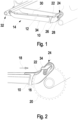
- the figures show two embodiments of a chainstay protection element in connection with the chainstay and possibly also the chainring, so that the chainstay system is also shown.
- the chainstay protection element has a cover element 10 .
- the cover element 10 is arranged on an outer side 12 of the chain stay 14 .
- the cover element 10 arranged in a region 16.
- the area 16 is an area of a chainring.
- the area 16 is the area adjoining a circumference of a chainring 20 counter to a direction of travel 18 .
- the cover element 10 could also be arranged somewhat wider or somewhat further forward in the direction of travel, so that this can be seen at least partially in plan view ( 2 ) below the chainring in particular the teeth of the chainring 20 is arranged.
- a fastening element 22 is connected to the cover element 10 or formed in one piece with it.
- the fastening element 22, which is arranged on an upper side of the chain stay 14, can effect fastening of the chain stay protective element to the chain stay 14 by means of a screw or the like.
- a chain guide element 24 is connected to the fastening element 22 .
- the chain guide element can also be connected in one piece to the fastening element 22 .
- the chain guide element 24 can also be part of the fastening element 22, so that it can be fastened, for example, via a screw 26 ( 1 ) he follows.
- the screw 26 is arranged in a slot so that the chain guide element 24 can be adjusted, in particular in the vertical direction. This is particularly advantageous when replacing the chain ring, since it is easy to adapt to chain rings of different sizes.
- a protective element 30 is connected to the cover element 10 or the fastening element 22 .
- the protective element 30 is arranged on an upper side of the chain stay 14 and encompasses the chain stay 14 in the exemplary embodiment shown on the outside 12 and on the opposite inside.
- the protective element is thus U-shaped in cross section.
- the protective element 30 extends in the illustrated exemplary embodiment over the entire length of the chainstay 12, starting from the end on the chainring side or starting from the cover element 10 in the direction of a dropout 32 of the rear structure, which serves to accommodate the rear wheel axle.
- the chain guide element can, as in particular figure 2 visible, be designed in such a way that it has a projection 34 which, in the assembled form, encompasses the chainring 20 or, in plan view ( 2 ) is arranged on the outside of the chainring 20.
- the cover element 10 can also be designed in such a way that it at least partially encompasses an underside 34 of the chain stay 14 in order to ensure a secure, reliable connection to the chain stay 14 .
- the cover element 10 also has a shoulder 36 .
- a groove 38 is formed by the extension 36, in which the teeth of the chain ring 20 are arranged.
- the projection 36 is thus arranged in front of or outside of the chain ring 20 in the assembled state in plan view.
- the fastening is preferably again carried out via a fastening element 22 which has a screw 40 in the exemplary embodiment shown.
Landscapes
- Engineering & Computer Science (AREA)
- Mechanical Engineering (AREA)
- Devices For Conveying Motion By Means Of Endless Flexible Members (AREA)
Applications Claiming Priority (1)
| Application Number | Priority Date | Filing Date | Title |
|---|---|---|---|
| DE202021105108.6U DE202021105108U1 (de) | 2021-09-22 | 2021-09-22 | Kettenstreben-Schutzelement sowie Kettenstreben-System |
Publications (2)
| Publication Number | Publication Date |
|---|---|
| EP4155176A1 true EP4155176A1 (fr) | 2023-03-29 |
| EP4155176B1 EP4155176B1 (fr) | 2024-05-29 |
Family
ID=83319240
Family Applications (1)
| Application Number | Title | Priority Date | Filing Date |
|---|---|---|---|
| EP22195265.8A Active EP4155176B1 (fr) | 2021-09-22 | 2022-09-13 | Élément de protection d'entretoise de chaîne et système d'entretoise de chaîne |
Country Status (4)
| Country | Link |
|---|---|
| US (1) | US20230092223A1 (fr) |
| EP (1) | EP4155176B1 (fr) |
| DE (1) | DE202021105108U1 (fr) |
| ES (1) | ES2985996T3 (fr) |
Families Citing this family (2)
| Publication number | Priority date | Publication date | Assignee | Title |
|---|---|---|---|---|
| US11110987B2 (en) * | 2018-04-13 | 2021-09-07 | Specialized Bicycle Components, Inc. | Chainstay protector with spaced protrusions |
| US12497119B2 (en) * | 2021-12-15 | 2025-12-16 | Bryce Barsnick | Motorbike swingarm cover |
Citations (3)
| Publication number | Priority date | Publication date | Assignee | Title |
|---|---|---|---|---|
| JPH0719969Y2 (ja) * | 1985-11-25 | 1995-05-10 | 松下電器産業株式会社 | チエンプロテクタ− |
| US20090295120A1 (en) * | 2008-06-03 | 2009-12-03 | Specialized Bicycle Components, Inc. | Bicycle chainstay protector |
| DE102012205182A1 (de) * | 2011-04-04 | 2012-10-04 | Specialized Bicycle Components, Inc. | Fahrrad-Kettenführungsanordnung |
Family Cites Families (6)
| Publication number | Priority date | Publication date | Assignee | Title |
|---|---|---|---|---|
| US445532A (en) | 1891-02-03 | Flush hinge portables | ||
| US20030236142A1 (en) | 2002-06-20 | 2003-12-25 | Shimano, Inc., A Japanese Corporation | Protective device for a bicycle rear derailleur |
| TWM242437U (en) | 2003-07-07 | 2004-09-01 | Ming-Hung Chen | Protective coil band for lower tube of bicycle rear fork |
| DE202014102807U1 (de) | 2014-06-18 | 2015-09-21 | Pending System Gmbh & Co. Kg | Kettenstrebenschutz |
| GB201514202D0 (en) | 2015-08-11 | 2015-09-23 | Bopworx Ltd | A protector |
| US11110987B2 (en) | 2018-04-13 | 2021-09-07 | Specialized Bicycle Components, Inc. | Chainstay protector with spaced protrusions |
-
2021
- 2021-09-22 DE DE202021105108.6U patent/DE202021105108U1/de active Active
-
2022
- 2022-09-13 EP EP22195265.8A patent/EP4155176B1/fr active Active
- 2022-09-13 ES ES22195265T patent/ES2985996T3/es active Active
- 2022-09-21 US US17/949,547 patent/US20230092223A1/en not_active Abandoned
Patent Citations (3)
| Publication number | Priority date | Publication date | Assignee | Title |
|---|---|---|---|---|
| JPH0719969Y2 (ja) * | 1985-11-25 | 1995-05-10 | 松下電器産業株式会社 | チエンプロテクタ− |
| US20090295120A1 (en) * | 2008-06-03 | 2009-12-03 | Specialized Bicycle Components, Inc. | Bicycle chainstay protector |
| DE102012205182A1 (de) * | 2011-04-04 | 2012-10-04 | Specialized Bicycle Components, Inc. | Fahrrad-Kettenführungsanordnung |
Also Published As
| Publication number | Publication date |
|---|---|
| ES2985996T3 (es) | 2024-11-08 |
| DE202021105108U1 (de) | 2022-12-23 |
| US20230092223A1 (en) | 2023-03-23 |
| EP4155176B1 (fr) | 2024-05-29 |
Similar Documents
| Publication | Publication Date | Title |
|---|---|---|
| DE102007033018B4 (de) | Fahrradvorderderailleur | |
| DE4230954A1 (de) | Lenkeraufbau für Fahrräder | |
| EP4155176B1 (fr) | Élément de protection d'entretoise de chaîne et système d'entretoise de chaîne | |
| DE102012205182A1 (de) | Fahrrad-Kettenführungsanordnung | |
| EP3736200B1 (fr) | Potence et système de potence | |
| DE102015221331B4 (de) | Vorderer Fahrrad-Kettenumwerfer mit Montagekonstruktion und Fahrradrahmen mit der Montagekonstruktion für den vorderen Fahrrad-Kettenumwerfer | |
| EP2168865B1 (fr) | Embrayage à chaîne pour un vélo | |
| DE2437893A1 (de) | Fahrrad | |
| AT518187B1 (de) | Kabelführungskörper | |
| DE102019101388A1 (de) | Fahrradkettenführungsvorrichtung | |
| DE19920979C2 (de) | Fahrradrahmen | |
| EP0785125A2 (fr) | Dispositif anti-rotation et antivol pour limiter l'extraction d'un support de selle ajustable hydrauliquement | |
| DE102016208997B4 (de) | Transportvorrichtung für ein Kind mit einer Handschutzvorrichtung | |
| DE20112448U1 (de) | Fahrradrahmen | |
| EP4025480B1 (fr) | Garde-chaîne pour vélo | |
| EP2511167A1 (fr) | Vélo et guide-chaîne | |
| EP3048034B1 (fr) | Protege-roues pour un velo comprenant une fourche de roue avant montee sur ressort | |
| EP2528804A1 (fr) | Tige de selle | |
| DE202024104497U1 (de) | Stoßdämpfungsvorrichtung für Fahrradgabelschäfte | |
| WO2023139219A1 (fr) | Dispositif destiné à fournir un couple de rappel pour un mécanisme de direction à deux roues | |
| DE29811484U1 (de) | Fahrradrahmen mit Stoßdämpfereinrichtung | |
| DE102015109041A1 (de) | Fahrrad mit einem Schmutzfänger als Fahrradstütze | |
| DE202009017380U1 (de) | Sicherheitslenker für ein Fahrrad | |
| DE202016004728U1 (de) | Griffelement | |
| DE202024107250U1 (de) | Fahrradschutzblechhalterung |
Legal Events
| Date | Code | Title | Description |
|---|---|---|---|
| PUAI | Public reference made under article 153(3) epc to a published international application that has entered the european phase |
Free format text: ORIGINAL CODE: 0009012 |
|
| STAA | Information on the status of an ep patent application or granted ep patent |
Free format text: STATUS: THE APPLICATION HAS BEEN PUBLISHED |
|
| AK | Designated contracting states |
Kind code of ref document: A1 Designated state(s): AL AT BE BG CH CY CZ DE DK EE ES FI FR GB GR HR HU IE IS IT LI LT LU LV MC MK MT NL NO PL PT RO RS SE SI SK SM TR |
|
| STAA | Information on the status of an ep patent application or granted ep patent |
Free format text: STATUS: REQUEST FOR EXAMINATION WAS MADE |
|
| 17P | Request for examination filed |
Effective date: 20230803 |
|
| RBV | Designated contracting states (corrected) |
Designated state(s): AL AT BE BG CH CY CZ DE DK EE ES FI FR GB GR HR HU IE IS IT LI LT LU LV MC MK MT NL NO PL PT RO RS SE SI SK SM TR |
|
| GRAP | Despatch of communication of intention to grant a patent |
Free format text: ORIGINAL CODE: EPIDOSNIGR1 |
|
| STAA | Information on the status of an ep patent application or granted ep patent |
Free format text: STATUS: GRANT OF PATENT IS INTENDED |
|
| INTG | Intention to grant announced |
Effective date: 20240115 |
|
| GRAS | Grant fee paid |
Free format text: ORIGINAL CODE: EPIDOSNIGR3 |
|
| GRAA | (expected) grant |
Free format text: ORIGINAL CODE: 0009210 |
|
| STAA | Information on the status of an ep patent application or granted ep patent |
Free format text: STATUS: THE PATENT HAS BEEN GRANTED |
|
| P01 | Opt-out of the competence of the unified patent court (upc) registered |
Effective date: 20240327 |
|
| AK | Designated contracting states |
Kind code of ref document: B1 Designated state(s): AL AT BE BG CH CY CZ DE DK EE ES FI FR GB GR HR HU IE IS IT LI LT LU LV MC MK MT NL NO PL PT RO RS SE SI SK SM TR |
|
| REG | Reference to a national code |
Ref country code: CH Ref legal event code: EP |
|
| REG | Reference to a national code |
Ref country code: IE Ref legal event code: FG4D Free format text: LANGUAGE OF EP DOCUMENT: GERMAN |
|
| REG | Reference to a national code |
Ref country code: DE Ref legal event code: R096 Ref document number: 502022000964 Country of ref document: DE |
|
| REG | Reference to a national code |
Ref country code: LT Ref legal event code: MG9D |
|
| REG | Reference to a national code |
Ref country code: NL Ref legal event code: MP Effective date: 20240529 |
|
| PG25 | Lapsed in a contracting state [announced via postgrant information from national office to epo] |
Ref country code: IS Free format text: LAPSE BECAUSE OF FAILURE TO SUBMIT A TRANSLATION OF THE DESCRIPTION OR TO PAY THE FEE WITHIN THE PRESCRIBED TIME-LIMIT Effective date: 20240929 |
|
| PG25 | Lapsed in a contracting state [announced via postgrant information from national office to epo] |
Ref country code: BG Free format text: LAPSE BECAUSE OF FAILURE TO SUBMIT A TRANSLATION OF THE DESCRIPTION OR TO PAY THE FEE WITHIN THE PRESCRIBED TIME-LIMIT Effective date: 20240529 |
|
| PG25 | Lapsed in a contracting state [announced via postgrant information from national office to epo] |
Ref country code: HR Free format text: LAPSE BECAUSE OF FAILURE TO SUBMIT A TRANSLATION OF THE DESCRIPTION OR TO PAY THE FEE WITHIN THE PRESCRIBED TIME-LIMIT Effective date: 20240529 Ref country code: FI Free format text: LAPSE BECAUSE OF FAILURE TO SUBMIT A TRANSLATION OF THE DESCRIPTION OR TO PAY THE FEE WITHIN THE PRESCRIBED TIME-LIMIT Effective date: 20240529 |
|
| PG25 | Lapsed in a contracting state [announced via postgrant information from national office to epo] |
Ref country code: GR Free format text: LAPSE BECAUSE OF FAILURE TO SUBMIT A TRANSLATION OF THE DESCRIPTION OR TO PAY THE FEE WITHIN THE PRESCRIBED TIME-LIMIT Effective date: 20240830 |
|
| PG25 | Lapsed in a contracting state [announced via postgrant information from national office to epo] |
Ref country code: PL Free format text: LAPSE BECAUSE OF FAILURE TO SUBMIT A TRANSLATION OF THE DESCRIPTION OR TO PAY THE FEE WITHIN THE PRESCRIBED TIME-LIMIT Effective date: 20240529 |
|
| PG25 | Lapsed in a contracting state [announced via postgrant information from national office to epo] |
Ref country code: LV Free format text: LAPSE BECAUSE OF FAILURE TO SUBMIT A TRANSLATION OF THE DESCRIPTION OR TO PAY THE FEE WITHIN THE PRESCRIBED TIME-LIMIT Effective date: 20240529 |
|
| PG25 | Lapsed in a contracting state [announced via postgrant information from national office to epo] |
Ref country code: PL Free format text: LAPSE BECAUSE OF FAILURE TO SUBMIT A TRANSLATION OF THE DESCRIPTION OR TO PAY THE FEE WITHIN THE PRESCRIBED TIME-LIMIT Effective date: 20240529 Ref country code: NO Free format text: LAPSE BECAUSE OF FAILURE TO SUBMIT A TRANSLATION OF THE DESCRIPTION OR TO PAY THE FEE WITHIN THE PRESCRIBED TIME-LIMIT Effective date: 20240829 Ref country code: LV Free format text: LAPSE BECAUSE OF FAILURE TO SUBMIT A TRANSLATION OF THE DESCRIPTION OR TO PAY THE FEE WITHIN THE PRESCRIBED TIME-LIMIT Effective date: 20240529 Ref country code: IS Free format text: LAPSE BECAUSE OF FAILURE TO SUBMIT A TRANSLATION OF THE DESCRIPTION OR TO PAY THE FEE WITHIN THE PRESCRIBED TIME-LIMIT Effective date: 20240929 Ref country code: HR Free format text: LAPSE BECAUSE OF FAILURE TO SUBMIT A TRANSLATION OF THE DESCRIPTION OR TO PAY THE FEE WITHIN THE PRESCRIBED TIME-LIMIT Effective date: 20240529 Ref country code: GR Free format text: LAPSE BECAUSE OF FAILURE TO SUBMIT A TRANSLATION OF THE DESCRIPTION OR TO PAY THE FEE WITHIN THE PRESCRIBED TIME-LIMIT Effective date: 20240830 Ref country code: FI Free format text: LAPSE BECAUSE OF FAILURE TO SUBMIT A TRANSLATION OF THE DESCRIPTION OR TO PAY THE FEE WITHIN THE PRESCRIBED TIME-LIMIT Effective date: 20240529 Ref country code: BG Free format text: LAPSE BECAUSE OF FAILURE TO SUBMIT A TRANSLATION OF THE DESCRIPTION OR TO PAY THE FEE WITHIN THE PRESCRIBED TIME-LIMIT Effective date: 20240529 Ref country code: RS Free format text: LAPSE BECAUSE OF FAILURE TO SUBMIT A TRANSLATION OF THE DESCRIPTION OR TO PAY THE FEE WITHIN THE PRESCRIBED TIME-LIMIT Effective date: 20240829 |
|
| REG | Reference to a national code |
Ref country code: ES Ref legal event code: FG2A Ref document number: 2985996 Country of ref document: ES Kind code of ref document: T3 Effective date: 20241108 |
|
| PG25 | Lapsed in a contracting state [announced via postgrant information from national office to epo] |
Ref country code: NL Free format text: LAPSE BECAUSE OF FAILURE TO SUBMIT A TRANSLATION OF THE DESCRIPTION OR TO PAY THE FEE WITHIN THE PRESCRIBED TIME-LIMIT Effective date: 20240529 |
|
| PG25 | Lapsed in a contracting state [announced via postgrant information from national office to epo] |
Ref country code: NL Free format text: LAPSE BECAUSE OF FAILURE TO SUBMIT A TRANSLATION OF THE DESCRIPTION OR TO PAY THE FEE WITHIN THE PRESCRIBED TIME-LIMIT Effective date: 20240529 |
|
| PG25 | Lapsed in a contracting state [announced via postgrant information from national office to epo] |
Ref country code: DK Free format text: LAPSE BECAUSE OF FAILURE TO SUBMIT A TRANSLATION OF THE DESCRIPTION OR TO PAY THE FEE WITHIN THE PRESCRIBED TIME-LIMIT Effective date: 20240529 |
|
| PG25 | Lapsed in a contracting state [announced via postgrant information from national office to epo] |
Ref country code: EE Free format text: LAPSE BECAUSE OF FAILURE TO SUBMIT A TRANSLATION OF THE DESCRIPTION OR TO PAY THE FEE WITHIN THE PRESCRIBED TIME-LIMIT Effective date: 20240529 |
|
| PG25 | Lapsed in a contracting state [announced via postgrant information from national office to epo] |
Ref country code: CZ Free format text: LAPSE BECAUSE OF FAILURE TO SUBMIT A TRANSLATION OF THE DESCRIPTION OR TO PAY THE FEE WITHIN THE PRESCRIBED TIME-LIMIT Effective date: 20240529 |
|
| PG25 | Lapsed in a contracting state [announced via postgrant information from national office to epo] |
Ref country code: RO Free format text: LAPSE BECAUSE OF FAILURE TO SUBMIT A TRANSLATION OF THE DESCRIPTION OR TO PAY THE FEE WITHIN THE PRESCRIBED TIME-LIMIT Effective date: 20240529 Ref country code: SK Free format text: LAPSE BECAUSE OF FAILURE TO SUBMIT A TRANSLATION OF THE DESCRIPTION OR TO PAY THE FEE WITHIN THE PRESCRIBED TIME-LIMIT Effective date: 20240529 |
|
| PG25 | Lapsed in a contracting state [announced via postgrant information from national office to epo] |
Ref country code: SM Free format text: LAPSE BECAUSE OF FAILURE TO SUBMIT A TRANSLATION OF THE DESCRIPTION OR TO PAY THE FEE WITHIN THE PRESCRIBED TIME-LIMIT Effective date: 20240529 |
|
| PG25 | Lapsed in a contracting state [announced via postgrant information from national office to epo] |
Ref country code: SM Free format text: LAPSE BECAUSE OF FAILURE TO SUBMIT A TRANSLATION OF THE DESCRIPTION OR TO PAY THE FEE WITHIN THE PRESCRIBED TIME-LIMIT Effective date: 20240529 Ref country code: SK Free format text: LAPSE BECAUSE OF FAILURE TO SUBMIT A TRANSLATION OF THE DESCRIPTION OR TO PAY THE FEE WITHIN THE PRESCRIBED TIME-LIMIT Effective date: 20240529 Ref country code: RO Free format text: LAPSE BECAUSE OF FAILURE TO SUBMIT A TRANSLATION OF THE DESCRIPTION OR TO PAY THE FEE WITHIN THE PRESCRIBED TIME-LIMIT Effective date: 20240529 Ref country code: EE Free format text: LAPSE BECAUSE OF FAILURE TO SUBMIT A TRANSLATION OF THE DESCRIPTION OR TO PAY THE FEE WITHIN THE PRESCRIBED TIME-LIMIT Effective date: 20240529 Ref country code: DK Free format text: LAPSE BECAUSE OF FAILURE TO SUBMIT A TRANSLATION OF THE DESCRIPTION OR TO PAY THE FEE WITHIN THE PRESCRIBED TIME-LIMIT Effective date: 20240529 Ref country code: CZ Free format text: LAPSE BECAUSE OF FAILURE TO SUBMIT A TRANSLATION OF THE DESCRIPTION OR TO PAY THE FEE WITHIN THE PRESCRIBED TIME-LIMIT Effective date: 20240529 |
|
| REG | Reference to a national code |
Ref country code: DE Ref legal event code: R097 Ref document number: 502022000964 Country of ref document: DE |
|
| PLBE | No opposition filed within time limit |
Free format text: ORIGINAL CODE: 0009261 |
|
| STAA | Information on the status of an ep patent application or granted ep patent |
Free format text: STATUS: NO OPPOSITION FILED WITHIN TIME LIMIT |
|
| PG25 | Lapsed in a contracting state [announced via postgrant information from national office to epo] |
Ref country code: MC Free format text: LAPSE BECAUSE OF FAILURE TO SUBMIT A TRANSLATION OF THE DESCRIPTION OR TO PAY THE FEE WITHIN THE PRESCRIBED TIME-LIMIT Effective date: 20240529 Ref country code: SI Free format text: LAPSE BECAUSE OF FAILURE TO SUBMIT A TRANSLATION OF THE DESCRIPTION OR TO PAY THE FEE WITHIN THE PRESCRIBED TIME-LIMIT Effective date: 20240529 |
|
| 26N | No opposition filed |
Effective date: 20250303 |
|
| PG25 | Lapsed in a contracting state [announced via postgrant information from national office to epo] |
Ref country code: LU Free format text: LAPSE BECAUSE OF NON-PAYMENT OF DUE FEES Effective date: 20240913 |
|
| REG | Reference to a national code |
Ref country code: BE Ref legal event code: MM Effective date: 20240930 |
|
| PG25 | Lapsed in a contracting state [announced via postgrant information from national office to epo] |
Ref country code: BE Free format text: LAPSE BECAUSE OF NON-PAYMENT OF DUE FEES Effective date: 20240930 |
|
| PG25 | Lapsed in a contracting state [announced via postgrant information from national office to epo] |
Ref country code: IE Free format text: LAPSE BECAUSE OF NON-PAYMENT OF DUE FEES Effective date: 20240913 |
|
| PG25 | Lapsed in a contracting state [announced via postgrant information from national office to epo] |
Ref country code: SE Free format text: LAPSE BECAUSE OF FAILURE TO SUBMIT A TRANSLATION OF THE DESCRIPTION OR TO PAY THE FEE WITHIN THE PRESCRIBED TIME-LIMIT Effective date: 20240529 |
|
| PGFP | Annual fee paid to national office [announced via postgrant information from national office to epo] |
Ref country code: DE Payment date: 20250915 Year of fee payment: 4 |
|
| PGFP | Annual fee paid to national office [announced via postgrant information from national office to epo] |
Ref country code: AT Payment date: 20251020 Year of fee payment: 4 Ref country code: FR Payment date: 20250922 Year of fee payment: 4 |
|
| PGFP | Annual fee paid to national office [announced via postgrant information from national office to epo] |
Ref country code: IT Payment date: 20250930 Year of fee payment: 4 |
|
| PG25 | Lapsed in a contracting state [announced via postgrant information from national office to epo] |
Ref country code: CY Free format text: LAPSE BECAUSE OF FAILURE TO SUBMIT A TRANSLATION OF THE DESCRIPTION OR TO PAY THE FEE WITHIN THE PRESCRIBED TIME-LIMIT; INVALID AB INITIO Effective date: 20220913 |
|
| PGFP | Annual fee paid to national office [announced via postgrant information from national office to epo] |
Ref country code: ES Payment date: 20251020 Year of fee payment: 4 |
|
| PG25 | Lapsed in a contracting state [announced via postgrant information from national office to epo] |
Ref country code: HU Free format text: LAPSE BECAUSE OF FAILURE TO SUBMIT A TRANSLATION OF THE DESCRIPTION OR TO PAY THE FEE WITHIN THE PRESCRIBED TIME-LIMIT; INVALID AB INITIO Effective date: 20220913 |
|
| REG | Reference to a national code |
Ref country code: CH Ref legal event code: H13 Free format text: ST27 STATUS EVENT CODE: U-0-0-H10-H13 (AS PROVIDED BY THE NATIONAL OFFICE) Effective date: 20260425 |