EP4155180B1 - Motocyclette électrique - Google Patents
Motocyclette électrique Download PDFInfo
- Publication number
- EP4155180B1 EP4155180B1 EP20961462.7A EP20961462A EP4155180B1 EP 4155180 B1 EP4155180 B1 EP 4155180B1 EP 20961462 A EP20961462 A EP 20961462A EP 4155180 B1 EP4155180 B1 EP 4155180B1
- Authority
- EP
- European Patent Office
- Prior art keywords
- frame
- electric motorcycle
- battery case
- controller
- cooling
- Prior art date
- Legal status (The legal status is an assumption and is not a legal conclusion. Google has not performed a legal analysis and makes no representation as to the accuracy of the status listed.)
- Active
Links
Images












Classifications
-
- B—PERFORMING OPERATIONS; TRANSPORTING
- B62—LAND VEHICLES FOR TRAVELLING OTHERWISE THAN ON RAILS
- B62K—CYCLES; CYCLE FRAMES; CYCLE STEERING DEVICES; RIDER-OPERATED TERMINAL CONTROLS SPECIALLY ADAPTED FOR CYCLES; CYCLE AXLE SUSPENSIONS; CYCLE SIDECARS, FORECARS, OR THE LIKE
- B62K25/00—Axle suspensions
- B62K25/04—Axle suspensions for mounting axles resiliently on cycle frame or fork
- B62K25/28—Axle suspensions for mounting axles resiliently on cycle frame or fork with pivoted chain-stay
- B62K25/283—Axle suspensions for mounting axles resiliently on cycle frame or fork with pivoted chain-stay for cycles without a pedal crank, e.g. motorcycles
-
- B—PERFORMING OPERATIONS; TRANSPORTING
- B60—VEHICLES IN GENERAL
- B60K—ARRANGEMENT OR MOUNTING OF PROPULSION UNITS OR OF TRANSMISSIONS IN VEHICLES; ARRANGEMENT OR MOUNTING OF PLURAL DIVERSE PRIME-MOVERS IN VEHICLES; AUXILIARY DRIVES FOR VEHICLES; INSTRUMENTATION OR DASHBOARDS FOR VEHICLES; ARRANGEMENTS IN CONNECTION WITH COOLING, AIR INTAKE, GAS EXHAUST OR FUEL SUPPLY OF PROPULSION UNITS IN VEHICLES
- B60K11/00—Arrangement in connection with cooling of propulsion units
- B60K11/02—Arrangement in connection with cooling of propulsion units with liquid cooling
-
- B—PERFORMING OPERATIONS; TRANSPORTING
- B60—VEHICLES IN GENERAL
- B60K—ARRANGEMENT OR MOUNTING OF PROPULSION UNITS OR OF TRANSMISSIONS IN VEHICLES; ARRANGEMENT OR MOUNTING OF PLURAL DIVERSE PRIME-MOVERS IN VEHICLES; AUXILIARY DRIVES FOR VEHICLES; INSTRUMENTATION OR DASHBOARDS FOR VEHICLES; ARRANGEMENTS IN CONNECTION WITH COOLING, AIR INTAKE, GAS EXHAUST OR FUEL SUPPLY OF PROPULSION UNITS IN VEHICLES
- B60K11/00—Arrangement in connection with cooling of propulsion units
- B60K11/02—Arrangement in connection with cooling of propulsion units with liquid cooling
- B60K11/04—Arrangement or mounting of radiators, radiator shutters, or radiator blinds
-
- B—PERFORMING OPERATIONS; TRANSPORTING
- B60—VEHICLES IN GENERAL
- B60L—PROPULSION OF ELECTRICALLY-PROPELLED VEHICLES; SUPPLYING ELECTRIC POWER FOR AUXILIARY EQUIPMENT OF ELECTRICALLY-PROPELLED VEHICLES; ELECTRODYNAMIC BRAKE SYSTEMS FOR VEHICLES IN GENERAL; MAGNETIC SUSPENSION OR LEVITATION FOR VEHICLES; MONITORING OPERATING VARIABLES OF ELECTRICALLY-PROPELLED VEHICLES; ELECTRIC SAFETY DEVICES FOR ELECTRICALLY-PROPELLED VEHICLES
- B60L50/00—Electric propulsion with power supplied within the vehicle
- B60L50/50—Electric propulsion with power supplied within the vehicle using propulsion power supplied by batteries or fuel cells
- B60L50/60—Electric propulsion with power supplied within the vehicle using propulsion power supplied by batteries or fuel cells using power supplied by batteries
-
- B—PERFORMING OPERATIONS; TRANSPORTING
- B60—VEHICLES IN GENERAL
- B60L—PROPULSION OF ELECTRICALLY-PROPELLED VEHICLES; SUPPLYING ELECTRIC POWER FOR AUXILIARY EQUIPMENT OF ELECTRICALLY-PROPELLED VEHICLES; ELECTRODYNAMIC BRAKE SYSTEMS FOR VEHICLES IN GENERAL; MAGNETIC SUSPENSION OR LEVITATION FOR VEHICLES; MONITORING OPERATING VARIABLES OF ELECTRICALLY-PROPELLED VEHICLES; ELECTRIC SAFETY DEVICES FOR ELECTRICALLY-PROPELLED VEHICLES
- B60L53/00—Methods of charging batteries, specially adapted for electric vehicles; Charging stations or on-board charging equipment therefor; Exchange of energy storage elements in electric vehicles
- B60L53/10—Methods of charging batteries, specially adapted for electric vehicles; Charging stations or on-board charging equipment therefor; Exchange of energy storage elements in electric vehicles characterised by the energy transfer between the charging station and the vehicle
- B60L53/14—Conductive energy transfer
- B60L53/16—Connectors, e.g. plugs or sockets, specially adapted for charging electric vehicles
-
- B—PERFORMING OPERATIONS; TRANSPORTING
- B62—LAND VEHICLES FOR TRAVELLING OTHERWISE THAN ON RAILS
- B62J—CYCLE SADDLES OR SEATS; AUXILIARY DEVICES OR ACCESSORIES SPECIALLY ADAPTED TO CYCLES AND NOT OTHERWISE PROVIDED FOR, e.g. ARTICLE CARRIERS OR CYCLE PROTECTORS
- B62J15/00—Mud-guards for wheels
- B62J15/02—Fastening means; Stays
-
- B—PERFORMING OPERATIONS; TRANSPORTING
- B62—LAND VEHICLES FOR TRAVELLING OTHERWISE THAN ON RAILS
- B62J—CYCLE SADDLES OR SEATS; AUXILIARY DEVICES OR ACCESSORIES SPECIALLY ADAPTED TO CYCLES AND NOT OTHERWISE PROVIDED FOR, e.g. ARTICLE CARRIERS OR CYCLE PROTECTORS
- B62J17/00—Weather guards for riders; Fairings or stream-lining parts not otherwise provided for
-
- B—PERFORMING OPERATIONS; TRANSPORTING
- B62—LAND VEHICLES FOR TRAVELLING OTHERWISE THAN ON RAILS
- B62J—CYCLE SADDLES OR SEATS; AUXILIARY DEVICES OR ACCESSORIES SPECIALLY ADAPTED TO CYCLES AND NOT OTHERWISE PROVIDED FOR, e.g. ARTICLE CARRIERS OR CYCLE PROTECTORS
- B62J17/00—Weather guards for riders; Fairings or stream-lining parts not otherwise provided for
- B62J17/02—Weather guards for riders; Fairings or stream-lining parts not otherwise provided for shielding only the rider's front
- B62J17/04—Windscreens
-
- B—PERFORMING OPERATIONS; TRANSPORTING
- B62—LAND VEHICLES FOR TRAVELLING OTHERWISE THAN ON RAILS
- B62J—CYCLE SADDLES OR SEATS; AUXILIARY DEVICES OR ACCESSORIES SPECIALLY ADAPTED TO CYCLES AND NOT OTHERWISE PROVIDED FOR, e.g. ARTICLE CARRIERS OR CYCLE PROTECTORS
- B62J23/00—Other protectors specially adapted for cycles
-
- B—PERFORMING OPERATIONS; TRANSPORTING
- B62—LAND VEHICLES FOR TRAVELLING OTHERWISE THAN ON RAILS
- B62J—CYCLE SADDLES OR SEATS; AUXILIARY DEVICES OR ACCESSORIES SPECIALLY ADAPTED TO CYCLES AND NOT OTHERWISE PROVIDED FOR, e.g. ARTICLE CARRIERS OR CYCLE PROTECTORS
- B62J27/00—Safety equipment
- B62J27/30—Crash bars; Crash bungs
-
- B—PERFORMING OPERATIONS; TRANSPORTING
- B62—LAND VEHICLES FOR TRAVELLING OTHERWISE THAN ON RAILS
- B62J—CYCLE SADDLES OR SEATS; AUXILIARY DEVICES OR ACCESSORIES SPECIALLY ADAPTED TO CYCLES AND NOT OTHERWISE PROVIDED FOR, e.g. ARTICLE CARRIERS OR CYCLE PROTECTORS
- B62J41/00—Arrangements of radiators, coolant hoses or pipes on cycles
-
- B—PERFORMING OPERATIONS; TRANSPORTING
- B62—LAND VEHICLES FOR TRAVELLING OTHERWISE THAN ON RAILS
- B62J—CYCLE SADDLES OR SEATS; AUXILIARY DEVICES OR ACCESSORIES SPECIALLY ADAPTED TO CYCLES AND NOT OTHERWISE PROVIDED FOR, e.g. ARTICLE CARRIERS OR CYCLE PROTECTORS
- B62J43/00—Arrangements of batteries
- B62J43/10—Arrangements of batteries for propulsion
- B62J43/16—Arrangements of batteries for propulsion on motorcycles or the like
-
- B—PERFORMING OPERATIONS; TRANSPORTING
- B62—LAND VEHICLES FOR TRAVELLING OTHERWISE THAN ON RAILS
- B62J—CYCLE SADDLES OR SEATS; AUXILIARY DEVICES OR ACCESSORIES SPECIALLY ADAPTED TO CYCLES AND NOT OTHERWISE PROVIDED FOR, e.g. ARTICLE CARRIERS OR CYCLE PROTECTORS
- B62J43/00—Arrangements of batteries
- B62J43/20—Arrangements of batteries characterised by the mounting
-
- B—PERFORMING OPERATIONS; TRANSPORTING
- B62—LAND VEHICLES FOR TRAVELLING OTHERWISE THAN ON RAILS
- B62J—CYCLE SADDLES OR SEATS; AUXILIARY DEVICES OR ACCESSORIES SPECIALLY ADAPTED TO CYCLES AND NOT OTHERWISE PROVIDED FOR, e.g. ARTICLE CARRIERS OR CYCLE PROTECTORS
- B62J43/00—Arrangements of batteries
- B62J43/20—Arrangements of batteries characterised by the mounting
- B62J43/28—Arrangements of batteries characterised by the mounting hidden within the cycle frame
-
- B—PERFORMING OPERATIONS; TRANSPORTING
- B62—LAND VEHICLES FOR TRAVELLING OTHERWISE THAN ON RAILS
- B62J—CYCLE SADDLES OR SEATS; AUXILIARY DEVICES OR ACCESSORIES SPECIALLY ADAPTED TO CYCLES AND NOT OTHERWISE PROVIDED FOR, e.g. ARTICLE CARRIERS OR CYCLE PROTECTORS
- B62J45/00—Electrical equipment arrangements specially adapted for use as accessories on cycles, not otherwise provided for
-
- B—PERFORMING OPERATIONS; TRANSPORTING
- B62—LAND VEHICLES FOR TRAVELLING OTHERWISE THAN ON RAILS
- B62J—CYCLE SADDLES OR SEATS; AUXILIARY DEVICES OR ACCESSORIES SPECIALLY ADAPTED TO CYCLES AND NOT OTHERWISE PROVIDED FOR, e.g. ARTICLE CARRIERS OR CYCLE PROTECTORS
- B62J45/00—Electrical equipment arrangements specially adapted for use as accessories on cycles, not otherwise provided for
- B62J45/20—Cycle computers as cycle accessories
-
- B—PERFORMING OPERATIONS; TRANSPORTING
- B62—LAND VEHICLES FOR TRAVELLING OTHERWISE THAN ON RAILS
- B62J—CYCLE SADDLES OR SEATS; AUXILIARY DEVICES OR ACCESSORIES SPECIALLY ADAPTED TO CYCLES AND NOT OTHERWISE PROVIDED FOR, e.g. ARTICLE CARRIERS OR CYCLE PROTECTORS
- B62J50/00—Arrangements specially adapted for use on cycles not provided for in main groups B62J1/00 - B62J45/00
- B62J50/30—Means for ventilation within devices provided on the cycle, e.g. ventilation means in a battery container
-
- B—PERFORMING OPERATIONS; TRANSPORTING
- B62—LAND VEHICLES FOR TRAVELLING OTHERWISE THAN ON RAILS
- B62J—CYCLE SADDLES OR SEATS; AUXILIARY DEVICES OR ACCESSORIES SPECIALLY ADAPTED TO CYCLES AND NOT OTHERWISE PROVIDED FOR, e.g. ARTICLE CARRIERS OR CYCLE PROTECTORS
- B62J6/00—Arrangement of optical signalling or lighting devices on cycles; Mounting or supporting thereof; Circuits therefor
- B62J6/02—Headlights
- B62J6/022—Headlights specially adapted for motorcycles or the like
- B62J6/027—Supporting means therefor, e.g. mounting brackets
-
- B—PERFORMING OPERATIONS; TRANSPORTING
- B62—LAND VEHICLES FOR TRAVELLING OTHERWISE THAN ON RAILS
- B62J—CYCLE SADDLES OR SEATS; AUXILIARY DEVICES OR ACCESSORIES SPECIALLY ADAPTED TO CYCLES AND NOT OTHERWISE PROVIDED FOR, e.g. ARTICLE CARRIERS OR CYCLE PROTECTORS
- B62J6/00—Arrangement of optical signalling or lighting devices on cycles; Mounting or supporting thereof; Circuits therefor
- B62J6/16—Arrangement of switches
-
- B—PERFORMING OPERATIONS; TRANSPORTING
- B62—LAND VEHICLES FOR TRAVELLING OTHERWISE THAN ON RAILS
- B62J—CYCLE SADDLES OR SEATS; AUXILIARY DEVICES OR ACCESSORIES SPECIALLY ADAPTED TO CYCLES AND NOT OTHERWISE PROVIDED FOR, e.g. ARTICLE CARRIERS OR CYCLE PROTECTORS
- B62J9/00—Containers specially adapted for cycles, e.g. panniers or saddle bags
- B62J9/10—Containers specially adapted for cycles, e.g. panniers or saddle bags integrated with the cycle
- B62J9/12—Containers specially adapted for cycles, e.g. panniers or saddle bags integrated with the cycle in the fairing
-
- B—PERFORMING OPERATIONS; TRANSPORTING
- B62—LAND VEHICLES FOR TRAVELLING OTHERWISE THAN ON RAILS
- B62J—CYCLE SADDLES OR SEATS; AUXILIARY DEVICES OR ACCESSORIES SPECIALLY ADAPTED TO CYCLES AND NOT OTHERWISE PROVIDED FOR, e.g. ARTICLE CARRIERS OR CYCLE PROTECTORS
- B62J9/00—Containers specially adapted for cycles, e.g. panniers or saddle bags
- B62J9/30—Containers specially adapted for cycles, e.g. panniers or saddle bags characterised by locking arrangements, e.g. top case locks integrated in a vehicle central locking system
-
- B—PERFORMING OPERATIONS; TRANSPORTING
- B62—LAND VEHICLES FOR TRAVELLING OTHERWISE THAN ON RAILS
- B62K—CYCLES; CYCLE FRAMES; CYCLE STEERING DEVICES; RIDER-OPERATED TERMINAL CONTROLS SPECIALLY ADAPTED FOR CYCLES; CYCLE AXLE SUSPENSIONS; CYCLE SIDECARS, FORECARS, OR THE LIKE
- B62K11/00—Motorcycles, engine-assisted cycles or motor scooters with one or two wheels
-
- B—PERFORMING OPERATIONS; TRANSPORTING
- B62—LAND VEHICLES FOR TRAVELLING OTHERWISE THAN ON RAILS
- B62K—CYCLES; CYCLE FRAMES; CYCLE STEERING DEVICES; RIDER-OPERATED TERMINAL CONTROLS SPECIALLY ADAPTED FOR CYCLES; CYCLE AXLE SUSPENSIONS; CYCLE SIDECARS, FORECARS, OR THE LIKE
- B62K11/00—Motorcycles, engine-assisted cycles or motor scooters with one or two wheels
- B62K11/02—Frames
- B62K11/04—Frames characterised by the engine being between front and rear wheels
-
- B—PERFORMING OPERATIONS; TRANSPORTING
- B62—LAND VEHICLES FOR TRAVELLING OTHERWISE THAN ON RAILS
- B62K—CYCLES; CYCLE FRAMES; CYCLE STEERING DEVICES; RIDER-OPERATED TERMINAL CONTROLS SPECIALLY ADAPTED FOR CYCLES; CYCLE AXLE SUSPENSIONS; CYCLE SIDECARS, FORECARS, OR THE LIKE
- B62K11/00—Motorcycles, engine-assisted cycles or motor scooters with one or two wheels
- B62K11/14—Handlebar constructions, or arrangements of controls thereon, specially adapted thereto
-
- B—PERFORMING OPERATIONS; TRANSPORTING
- B62—LAND VEHICLES FOR TRAVELLING OTHERWISE THAN ON RAILS
- B62K—CYCLES; CYCLE FRAMES; CYCLE STEERING DEVICES; RIDER-OPERATED TERMINAL CONTROLS SPECIALLY ADAPTED FOR CYCLES; CYCLE AXLE SUSPENSIONS; CYCLE SIDECARS, FORECARS, OR THE LIKE
- B62K19/00—Cycle frames
- B62K19/18—Joints between frame members
- B62K19/28—Means for strengthening joints
-
- B—PERFORMING OPERATIONS; TRANSPORTING
- B62—LAND VEHICLES FOR TRAVELLING OTHERWISE THAN ON RAILS
- B62K—CYCLES; CYCLE FRAMES; CYCLE STEERING DEVICES; RIDER-OPERATED TERMINAL CONTROLS SPECIALLY ADAPTED FOR CYCLES; CYCLE AXLE SUSPENSIONS; CYCLE SIDECARS, FORECARS, OR THE LIKE
- B62K19/00—Cycle frames
- B62K19/30—Frame parts shaped to receive other cycle parts or accessories
-
- B—PERFORMING OPERATIONS; TRANSPORTING
- B62—LAND VEHICLES FOR TRAVELLING OTHERWISE THAN ON RAILS
- B62K—CYCLES; CYCLE FRAMES; CYCLE STEERING DEVICES; RIDER-OPERATED TERMINAL CONTROLS SPECIALLY ADAPTED FOR CYCLES; CYCLE AXLE SUSPENSIONS; CYCLE SIDECARS, FORECARS, OR THE LIKE
- B62K23/00—Rider-operated controls specially adapted for cycles, i.e. means for initiating control operations, e.g. levers, grips
- B62K23/02—Rider-operated controls specially adapted for cycles, i.e. means for initiating control operations, e.g. levers, grips hand actuated
-
- B—PERFORMING OPERATIONS; TRANSPORTING
- B62—LAND VEHICLES FOR TRAVELLING OTHERWISE THAN ON RAILS
- B62M—RIDER PROPULSION OF WHEELED VEHICLES OR SLEDGES; POWERED PROPULSION OF SLEDGES OR SINGLE-TRACK CYCLES; TRANSMISSIONS SPECIALLY ADAPTED FOR SUCH VEHICLES
- B62M7/00—Motorcycles characterised by position of motor or engine
- B62M7/02—Motorcycles characterised by position of motor or engine with engine between front and rear wheels
- B62M7/04—Motorcycles characterised by position of motor or engine with engine between front and rear wheels below the frame
-
- B—PERFORMING OPERATIONS; TRANSPORTING
- B62—LAND VEHICLES FOR TRAVELLING OTHERWISE THAN ON RAILS
- B62M—RIDER PROPULSION OF WHEELED VEHICLES OR SLEDGES; POWERED PROPULSION OF SLEDGES OR SINGLE-TRACK CYCLES; TRANSMISSIONS SPECIALLY ADAPTED FOR SUCH VEHICLES
- B62M9/00—Transmissions characterised by use of an endless chain, belt, or the like
- B62M9/02—Transmissions characterised by use of an endless chain, belt, or the like of unchangeable ratio
-
- H—ELECTRICITY
- H01—ELECTRIC ELEMENTS
- H01M—PROCESSES OR MEANS, e.g. BATTERIES, FOR THE DIRECT CONVERSION OF CHEMICAL ENERGY INTO ELECTRICAL ENERGY
- H01M10/00—Secondary cells; Manufacture thereof
- H01M10/60—Heating or cooling; Temperature control
- H01M10/61—Types of temperature control
- H01M10/613—Cooling or keeping cold
-
- H—ELECTRICITY
- H01—ELECTRIC ELEMENTS
- H01M—PROCESSES OR MEANS, e.g. BATTERIES, FOR THE DIRECT CONVERSION OF CHEMICAL ENERGY INTO ELECTRICAL ENERGY
- H01M10/00—Secondary cells; Manufacture thereof
- H01M10/60—Heating or cooling; Temperature control
- H01M10/62—Heating or cooling; Temperature control specially adapted for specific applications
- H01M10/625—Vehicles
-
- H—ELECTRICITY
- H01—ELECTRIC ELEMENTS
- H01M—PROCESSES OR MEANS, e.g. BATTERIES, FOR THE DIRECT CONVERSION OF CHEMICAL ENERGY INTO ELECTRICAL ENERGY
- H01M10/00—Secondary cells; Manufacture thereof
- H01M10/60—Heating or cooling; Temperature control
- H01M10/65—Means for temperature control structurally associated with the cells
- H01M10/655—Solid structures for heat exchange or heat conduction
- H01M10/6551—Surfaces specially adapted for heat dissipation or radiation, e.g. fins or coatings
-
- H—ELECTRICITY
- H01—ELECTRIC ELEMENTS
- H01M—PROCESSES OR MEANS, e.g. BATTERIES, FOR THE DIRECT CONVERSION OF CHEMICAL ENERGY INTO ELECTRICAL ENERGY
- H01M10/00—Secondary cells; Manufacture thereof
- H01M10/60—Heating or cooling; Temperature control
- H01M10/65—Means for temperature control structurally associated with the cells
- H01M10/656—Means for temperature control structurally associated with the cells characterised by the type of heat-exchange fluid
- H01M10/6561—Gases
- H01M10/6563—Gases with forced flow, e.g. by blowers
-
- H—ELECTRICITY
- H01—ELECTRIC ELEMENTS
- H01M—PROCESSES OR MEANS, e.g. BATTERIES, FOR THE DIRECT CONVERSION OF CHEMICAL ENERGY INTO ELECTRICAL ENERGY
- H01M10/00—Secondary cells; Manufacture thereof
- H01M10/60—Heating or cooling; Temperature control
- H01M10/65—Means for temperature control structurally associated with the cells
- H01M10/656—Means for temperature control structurally associated with the cells characterised by the type of heat-exchange fluid
- H01M10/6567—Liquids
- H01M10/6568—Liquids characterised by flow circuits, e.g. loops, located externally to the cells or cell casings
-
- H—ELECTRICITY
- H02—GENERATION; CONVERSION OR DISTRIBUTION OF ELECTRIC POWER
- H02K—DYNAMO-ELECTRIC MACHINES
- H02K9/00—Arrangements for cooling or ventilating
- H02K9/19—Arrangements for cooling or ventilating for machines with closed casing and closed-circuit cooling using a liquid cooling medium, e.g. oil
- H02K9/193—Arrangements for cooling or ventilating for machines with closed casing and closed-circuit cooling using a liquid cooling medium, e.g. oil with provision for replenishing the cooling medium; with means for preventing leakage of the cooling medium
-
- B—PERFORMING OPERATIONS; TRANSPORTING
- B62—LAND VEHICLES FOR TRAVELLING OTHERWISE THAN ON RAILS
- B62H—CYCLE STANDS; SUPPORTS OR HOLDERS FOR PARKING OR STORING CYCLES; APPLIANCES PREVENTING OR INDICATING UNAUTHORIZED USE OR THEFT OF CYCLES; LOCKS INTEGRAL WITH CYCLES; DEVICES FOR LEARNING TO RIDE CYCLES
- B62H1/00—Supports or stands forming part of or attached to cycles
- B62H1/02—Articulated stands, e.g. in the shape of hinged arms
- B62H1/04—Substantially U-shaped stands for embracing the rear wheel
-
- B—PERFORMING OPERATIONS; TRANSPORTING
- B62—LAND VEHICLES FOR TRAVELLING OTHERWISE THAN ON RAILS
- B62J—CYCLE SADDLES OR SEATS; AUXILIARY DEVICES OR ACCESSORIES SPECIALLY ADAPTED TO CYCLES AND NOT OTHERWISE PROVIDED FOR, e.g. ARTICLE CARRIERS OR CYCLE PROTECTORS
- B62J1/00—Saddles or other seats for cycles; Arrangement thereof; Component parts
- B62J1/28—Other additional equipment, e.g. back-rests for children
-
- B—PERFORMING OPERATIONS; TRANSPORTING
- B62—LAND VEHICLES FOR TRAVELLING OTHERWISE THAN ON RAILS
- B62J—CYCLE SADDLES OR SEATS; AUXILIARY DEVICES OR ACCESSORIES SPECIALLY ADAPTED TO CYCLES AND NOT OTHERWISE PROVIDED FOR, e.g. ARTICLE CARRIERS OR CYCLE PROTECTORS
- B62J25/00—Foot-rests; Knee grips; Passenger hand-grips
- B62J25/06—Bar-type foot rests
-
- B—PERFORMING OPERATIONS; TRANSPORTING
- B62—LAND VEHICLES FOR TRAVELLING OTHERWISE THAN ON RAILS
- B62J—CYCLE SADDLES OR SEATS; AUXILIARY DEVICES OR ACCESSORIES SPECIALLY ADAPTED TO CYCLES AND NOT OTHERWISE PROVIDED FOR, e.g. ARTICLE CARRIERS OR CYCLE PROTECTORS
- B62J9/00—Containers specially adapted for cycles, e.g. panniers or saddle bags
- B62J9/20—Containers specially adapted for cycles, e.g. panniers or saddle bags attached to the cycle as accessories
- B62J9/23—Containers specially adapted for cycles, e.g. panniers or saddle bags attached to the cycle as accessories above or alongside the rear wheel
-
- B—PERFORMING OPERATIONS; TRANSPORTING
- B62—LAND VEHICLES FOR TRAVELLING OTHERWISE THAN ON RAILS
- B62K—CYCLES; CYCLE FRAMES; CYCLE STEERING DEVICES; RIDER-OPERATED TERMINAL CONTROLS SPECIALLY ADAPTED FOR CYCLES; CYCLE AXLE SUSPENSIONS; CYCLE SIDECARS, FORECARS, OR THE LIKE
- B62K2204/00—Adaptations for driving cycles by electric motor
-
- F—MECHANICAL ENGINEERING; LIGHTING; HEATING; WEAPONS; BLASTING
- F16—ENGINEERING ELEMENTS AND UNITS; GENERAL MEASURES FOR PRODUCING AND MAINTAINING EFFECTIVE FUNCTIONING OF MACHINES OR INSTALLATIONS; THERMAL INSULATION IN GENERAL
- F16H—GEARING
- F16H55/00—Elements with teeth or friction surfaces for conveying motion; Worms, pulleys or sheaves for gearing mechanisms
- F16H55/32—Friction members
- F16H55/36—Pulleys
-
- H—ELECTRICITY
- H01—ELECTRIC ELEMENTS
- H01M—PROCESSES OR MEANS, e.g. BATTERIES, FOR THE DIRECT CONVERSION OF CHEMICAL ENERGY INTO ELECTRICAL ENERGY
- H01M2220/00—Batteries for particular applications
- H01M2220/20—Batteries in motive systems, e.g. vehicle, ship, plane
-
- Y—GENERAL TAGGING OF NEW TECHNOLOGICAL DEVELOPMENTS; GENERAL TAGGING OF CROSS-SECTIONAL TECHNOLOGIES SPANNING OVER SEVERAL SECTIONS OF THE IPC; TECHNICAL SUBJECTS COVERED BY FORMER USPC CROSS-REFERENCE ART COLLECTIONS [XRACs] AND DIGESTS
- Y02—TECHNOLOGIES OR APPLICATIONS FOR MITIGATION OR ADAPTATION AGAINST CLIMATE CHANGE
- Y02E—REDUCTION OF GREENHOUSE GAS [GHG] EMISSIONS, RELATED TO ENERGY GENERATION, TRANSMISSION OR DISTRIBUTION
- Y02E60/00—Enabling technologies; Technologies with a potential or indirect contribution to GHG emissions mitigation
- Y02E60/10—Energy storage using batteries
-
- Y—GENERAL TAGGING OF NEW TECHNOLOGICAL DEVELOPMENTS; GENERAL TAGGING OF CROSS-SECTIONAL TECHNOLOGIES SPANNING OVER SEVERAL SECTIONS OF THE IPC; TECHNICAL SUBJECTS COVERED BY FORMER USPC CROSS-REFERENCE ART COLLECTIONS [XRACs] AND DIGESTS
- Y02—TECHNOLOGIES OR APPLICATIONS FOR MITIGATION OR ADAPTATION AGAINST CLIMATE CHANGE
- Y02T—CLIMATE CHANGE MITIGATION TECHNOLOGIES RELATED TO TRANSPORTATION
- Y02T10/00—Road transport of goods or passengers
- Y02T10/60—Other road transportation technologies with climate change mitigation effect
- Y02T10/64—Electric machine technologies in electromobility
-
- Y—GENERAL TAGGING OF NEW TECHNOLOGICAL DEVELOPMENTS; GENERAL TAGGING OF CROSS-SECTIONAL TECHNOLOGIES SPANNING OVER SEVERAL SECTIONS OF THE IPC; TECHNICAL SUBJECTS COVERED BY FORMER USPC CROSS-REFERENCE ART COLLECTIONS [XRACs] AND DIGESTS
- Y02—TECHNOLOGIES OR APPLICATIONS FOR MITIGATION OR ADAPTATION AGAINST CLIMATE CHANGE
- Y02T—CLIMATE CHANGE MITIGATION TECHNOLOGIES RELATED TO TRANSPORTATION
- Y02T10/00—Road transport of goods or passengers
- Y02T10/60—Other road transportation technologies with climate change mitigation effect
- Y02T10/70—Energy storage systems for electromobility, e.g. batteries
-
- Y—GENERAL TAGGING OF NEW TECHNOLOGICAL DEVELOPMENTS; GENERAL TAGGING OF CROSS-SECTIONAL TECHNOLOGIES SPANNING OVER SEVERAL SECTIONS OF THE IPC; TECHNICAL SUBJECTS COVERED BY FORMER USPC CROSS-REFERENCE ART COLLECTIONS [XRACs] AND DIGESTS
- Y02—TECHNOLOGIES OR APPLICATIONS FOR MITIGATION OR ADAPTATION AGAINST CLIMATE CHANGE
- Y02T—CLIMATE CHANGE MITIGATION TECHNOLOGIES RELATED TO TRANSPORTATION
- Y02T10/00—Road transport of goods or passengers
- Y02T10/60—Other road transportation technologies with climate change mitigation effect
- Y02T10/7072—Electromobility specific charging systems or methods for batteries, ultracapacitors, supercapacitors or double-layer capacitors
-
- Y—GENERAL TAGGING OF NEW TECHNOLOGICAL DEVELOPMENTS; GENERAL TAGGING OF CROSS-SECTIONAL TECHNOLOGIES SPANNING OVER SEVERAL SECTIONS OF THE IPC; TECHNICAL SUBJECTS COVERED BY FORMER USPC CROSS-REFERENCE ART COLLECTIONS [XRACs] AND DIGESTS
- Y02—TECHNOLOGIES OR APPLICATIONS FOR MITIGATION OR ADAPTATION AGAINST CLIMATE CHANGE
- Y02T—CLIMATE CHANGE MITIGATION TECHNOLOGIES RELATED TO TRANSPORTATION
- Y02T10/00—Road transport of goods or passengers
- Y02T10/60—Other road transportation technologies with climate change mitigation effect
- Y02T10/72—Electric energy management in electromobility
-
- Y—GENERAL TAGGING OF NEW TECHNOLOGICAL DEVELOPMENTS; GENERAL TAGGING OF CROSS-SECTIONAL TECHNOLOGIES SPANNING OVER SEVERAL SECTIONS OF THE IPC; TECHNICAL SUBJECTS COVERED BY FORMER USPC CROSS-REFERENCE ART COLLECTIONS [XRACs] AND DIGESTS
- Y02—TECHNOLOGIES OR APPLICATIONS FOR MITIGATION OR ADAPTATION AGAINST CLIMATE CHANGE
- Y02T—CLIMATE CHANGE MITIGATION TECHNOLOGIES RELATED TO TRANSPORTATION
- Y02T90/00—Enabling technologies or technologies with a potential or indirect contribution to GHG emissions mitigation
- Y02T90/10—Technologies relating to charging of electric vehicles
- Y02T90/14—Plug-in electric vehicles
Definitions
- the disclosure relates to the field of electric motorcycle.
- the electric motorcycle is one of the electric vehicles, which provides electric power to the electric motor by a battery pack with electricity stored, and then the electric motor drives the rear wheel of the electric motorcycle to rotate, so that the electric motorcycle can run on the ground.
- WO2020188706 discloses the preamble of claim 1.
- the national standard General Technical Conditions for Electric motorcycles and Electric Mopeds (hereinafter referred to as the "electric motorcycle standard") was issued on June 25, 2009 and implemented on January 1, 2010. According to this standard, two or three wheeled vehicles with a maximum design speed of greater than 20 km/h and less than 50 km/h and driven by electricity are called mopeds or electric motorcycles, and electric motorcycles or mopeds are included in the category of motor vehicles.
- the maximum speed of the electric motorcycle is below 50 km/h. At this speed, the vibration frequency of the electric motorcycle is small, and the requirements for the vehicle body strength and battery endurance are small. However, when the speed of the electric motorcycle is increased to greater than 50 km/h, the vibration frequency of the electric motorcycle increases, and the requirements for the vehicle body strength and the power storage capacity of the battery are high.
- the object of the disclosure is to provide an electric motorcycle with improved safety when running at a speed of greater than 50 km/h.
- An electric motorcycle includes a frame, a front wheel, a rear wheel, a front suspension, a rear suspension, a steering system, an electric motor, a battery pack, a charging device, a controller, a plurality of seats, a dashboard panel, a front cowling, a plurality of lights, a side box, and a vehicle cover.
- the battery pack, the controller and the charging device are all disposed on the frame.
- the battery pack provides electric power for the electric equipment on the electric motorcycle, and the charging device converts the electric energy of the public grid into DC to charge the battery pack.
- the controller is connected to the electric motor by wires, and the controller controls the electric motor.
- the battery pack, the controller and the charging device are arranged in sequence along the height direction of the frame.
- the battery pack and the charging device are positioned on the frame adjacent to the front wheel.
- the controller is arranged on the battery pack.
- the battery bank comprises a battery and a battery case, the battery is arranged within the battery case.
- the battery case is connected to the frame.
- the battery case is connected to the frame to enhance the strength of the frame.
- the structure of the battery bank on the frame is compact, improving the stability of the electric motorcycle.
- the frame comprises a front frame adjacent to the front wheel and a rear frame adjacent to the rear wheel, the side of the battery case adjacent to the front wheel is connected to the front frame, and the side of the battery case adjacent to the rear wheel is connected to the rear frame.
- the side of the battery case adjacent to the front wheel is provided with a first connection seat, a second connection seat and a third connection seat.
- the side of the battery case adjacent to the rear frame is provided with a fourth connection seat and a fifth connection seat.
- the front frame is connected to the first connection seat, the second connection seat and the third connection seat by shafts.
- the rear frame is connected to the fourth connection seat and the fifth connection seat by shafts.
- the battery case comprises a body case and a plurality of side plates which are fixed on the body case by bolts.
- the side plates are provided with a plurality of ribs.
- the ribs increase the surface area of the battery case and improve the heat dissipation of the battery bank. At the same time, the strength of the battery case is enhanced, thereby improving the safety of the electric motorcycle.
- the bottom of the battery case is provided with a plurality of indentations, a cushion block is arranged between two adjacent indentations, the upper end surface of the cushion block is flat with the upper end surface of the indentation.
- each cushion block is arranged on each cushion block.
- the electric motorcycle is provided with a cooling air passage for cooling the battery bank.
- the heat can be quickly dissipated from the battery bank, which can make the working temperature of the battery bank within the preset range and reduce the electricity loss of battery bank when the electric motorcycle is running at high speed, thereby ensuring the safety and endurance of the electric motorcycle.
- the cooling air passage is a passage formed around the battery bank and the space between the vehicle cover and the battery bank.
- the frame is provided with a water-cooling device, which includes a water tank, a water pump connected to the water tank by a pipe and a cooling pipe connected to the water pump.
- the cooling pipe is arranged on the battery bank, and the cooling pipe is connected to a return pipe, the return pipe is connected to the water tank.
- the battery bank can keep running at low temperature to improve the safety of the electric motorcycle when the electric motorcycle is running at high speed.
- a plurality of radiating fins is arranged on the side wall of the water tank.
- the water-cooling device also includes a radiator fan, the radiating fan corresponds to the water tank.
- the controller is placed at one end of the battery case adjacent to the dashboard panel.
- the controller can keep running at low temperature to improve the safety of the electric motorcycle when the electric motorcycle is running at high speed.
- an installation site is arranged on the battery case and a groove is arranged on the installation site, the controller is installed on the installation site and fixed on the battery case by screws.
- the frame is provided with a water-cooling device
- the water-cooling device includes a water tank, a cooling pipe connected to the water tank and a water pump connected to the cooling pipe, and the cooling pipe is at least partially arranged on the controller.
- the controller is provided with a coolant channel, the coolant channel is provided with an inlet and an outlet; a coolant pipe comprises a second branch pipe connected to the inlet of the coolant channel and a third branch pipe connected to the outlet of the coolant channel, and the second branch pipe is connected to a water pump, and the third branch pipe is connected to a water tank.
- a plurality of radiating fins is arranged on the side wall of the water tank.
- the water-cooling device further comprises a plurality of radiating fans arranged on the frame or the water tank, and the radiating fans corresponds to the water tank.
- the water-cooling device further comprises an auxiliary water tank arranged on the frame, the auxiliary water tank is connected to the water tank by a pipeline, and the coolant is pumped from the auxiliary water tank into the water tank through negative pressure.
- the coolant in the auxiliary water tank is automatically replenished to the water tank to maintain the flow of coolant through the controller and maintain the constant heat dissipation performance of the controller.
- the frame or controller is provided with a cooling fan for cooling the controller.
- the air inlet of the cooling fan faces toward the rear wheel, and the air outlet of the cooling fan faces toward the controller.
- the controller is provided with a wire connector.
- the wire connector is connected to the electric motor by cables.
- the charging device is arranged on the frame, and the controller is positioned between the charging device and the battery bank.
- the charging device is provided with a charging connector, and the charging connector faces the seats.
- the axis along the length direction of the charging connector is defined as a straight line L1
- the line connecting the center point of the front wheel and the center point of the rear wheel is defined as a straight line L2
- an angle is defined by a straight line L1 and the straight line L2, and the angle is in the range from 30° to 60°.
- the charging connector is detachably connected to a sealing plug.
- the sealing plug is waterproof and dust-proof, protecting the charging connector from leakage, and ensuring the safety of electric motorcycle.
- the sealing plug includes a sealing plug and a plug cap, on which a connecting rope is arranged, and one end of the connecting rope is connected to the charging connector.
- a charging port corresponding to the charging connector is arranged on the vehicle cover, and a charging port cover for closing the charging port is connected to the vehicle cover.
- the charging port cover protects the charging connector, improving the safety of electric motorcycle.
- the surface of the charging port cover is smoothly incorporated into the surface of the vehicle cover.
- the charging port cover is connected to the vehicle cover by a locking structure, and the charging port cover is turned and opened towards the dashboard panel.
- the locking structure includes a connecting rod connected to one side of the charging port cover, a rotating shaft connected to the connecting rod, a torsional spring arranged on the rotating shaft, and a button arranged on the charging port cover.
- the rotating shaft is rotatably arranged on the vehicle cover, an elastic member is arranged between the button and a bottom plate.
- a rotating shaft mounting part is arranged on the vehicle cover, and two ends of the rotating shaft is rotatably arranged on the rotating shaft mounting part.
- a damping member is disposed on the connection between the rotating shaft and the vehicle cover.
- the charging port cover comprises a cover plate and a bottom plate, a cavity is defined by the cover plate and the bottom plate, a first recess is defined at the end of the cover plate facing the dashboard panel, a second recess is defined at the end of the cover plate facing the seats, the connecting rod is connected to the first recess, and a button is arranged in the second recess.
- the sealing plug is a part of the charging port cover.
- the sealing plug is a part of the charging port cover, which can be opened during charging, improving the overall strength of the vehicle.
- the charging device is provided with a cooling fan, the air inlet of the cooling fan faces the seats, and the air outlet of the cooling fan faces the interior of the charging device.
- the charging device includes at least two cooling fans, and the two cooling fans are symmetrically arranged on two sides of the charging connector, respectively.
- the two cooling fans are symmetrically arranged to evenly dissipate the heat from the charging device.
- the charging device is provided with a plurality of air outlets, which face toward the dashboard panel.
- the frame is provided with a water-cooling device for cooling the charging device.
- the water-cooling device includes a water tank, a cooling pipe connected to the water tank and a water pump connected to the cooling pipe.
- the cooling pipe is partially arranged on the charging device.
- a plurality of radiating fins are arranged on the side wall of the water tank.
- the water-cooling device further includes a radiating fan for cooling the water tank arranged on the frame or the water tank.
- the water-cooling device further comprises an auxiliary water tank arranged on the frame, the auxiliary water tank is connected to the water tank by a pipeline, and the coolant is pumped from the auxiliary water tank into the water tank through negative pressure.
- the coolant in the auxiliary water tank is automatically replenished to the water tank to maintain the heat dissipation performance of the water-cooling device for the controller.
- the rear suspension includes a rear fork and a shock absorber connected to the frame by a shaft, the rear fork is connected to the rear wheel, and the electric motor is arranged on the rear fork.
- the electric motor then moves synchronously with the rear fork, and the tightness of the timing belt remains unchanged.
- the electric motor is arranged on the end of the rear fork away from the rear wheel.
- the rear fork includes two symmetrical support plates, and the electric motor is positioned between the two support plates.
- one end of the rear fork is movably connected to a connecting lugs on the battery case by shafts.
- the shock absorber includes a telescopic rod and a shock absorption spring sleeved on the telescopic rod.
- One end of the telescopic rod is connected to the connecting lugs by shafts, and the other end is connected to the rear fork by shafts.
- the telescopic rod includes a sleeve, a rod body and a joint connected to the rod body.
- the joint is connected to the connecting lugs by shafts, and the rod body is inserted into the sleeve.
- the sleeve body is provided with a first stopper
- the rod body is provided with a second stopper.
- One end of the damping spring is connected to the first stopper, and the other end is connected to the second stopper.
- the telescopic rod body is provided with an elastic shock pad.
- the rear fork is fixed with a rear fender by screws, and the rear fender corresponds to the rear wheel.
- one end of the rear fender is connected to the rear fork, and the other end is suspended in midair; the rear fender portion is folded to form a connection part, and the connection part is connected to the rear fork by screws.
- the electric motorcycle further includes a steering system
- the steering system comprises a steering handle, an electronic-controlled throttle and a switch assembly are arranged on the steering handle, wherein the switch assembly is provided with a first operation area, a second operation area and a third operation area that are able to be operated easily by the thumb, the switch assembly is also provided with a fourth operation area that is able to be operated by the index finger.
- a cutting plane is made along the thickness direction of the switch assembly, an origin point is defined as the center point of the cavity of the switch assembly on the steering handle, a x-axis is defined as the length direction of the electric motorcycle, and a y-axis is defined as the height direction of the electric motorcycle, and the projection of the first operation area on the cutting plane coordinate system xoy is in the scanning area of -45- 0°.
- a cutting plane is made along the thickness direction of the switch assembly, an origin point is defined as the center point of the cavity of the switch assembly on the steering handle, an x-axis is defined as the length direction of the electric motorcycle, and a y-axis is defined as the height direction of the electric motorcycle, and the projection of the second operation area on the cutting plane coordinate system xoy is in the scanning area of 0- 45°.
- a cutting plane is made along the thickness direction of the switch assembly, an origin point is defined as the center point of the cavity of the switch assembly on the steering handle, an x-axis is defined as the length direction of the electric motorcycle, and a y-axis is defined as the height direction of the electric motorcycle, and the projection of the third operation area on the cutting plane coordinate system xoy is in the scanning area of 45- 90°.
- a cutting plane is made along the thickness direction of the switch assembly, an origin point is defined as the center point of the cavity of the switch assembly on the steering handle, an x-axis is defined as the length direction of the electric motorcycle, and a y-axis is defined as the height direction of the electric motorcycle, and the projection of the fourth operation area on the cutting plane coordinate system xoy is in the scanning area of 90- 135°.
- the first operation area is provided with a horn button and a turn signal light button.
- the first operation area is also provided with a photographing button.
- the second operation area is provided with a power assisted pushing button and a shift button.
- the third operation area is provided with a multifunction button and a loudspeaker on/off button.
- the multifunction button includes a lifting button and a switching button.
- the lifting button is provided with a concave portion, and the switching button is partially inserted into the concave portion after the switching button moves toward the steering handle.
- the fourth operation area is provided with a high beam light on/off button.
- a front cowling is arranged on the frame, and a windshield is arranged on the front cowling.
- the windshield is fitted with the front cowling, and the lifting button controls the lifting of the windshield.
- the middle of the windshield protrudes along the direction of the rear wheel towards the shroud, forming an arched section.
- the front cowling is provided with a windshield, which is fitted with the windshield, thereby forming a middle projection, and two sides is arranged to the side opposite to the middle projection.
- the windshield is liftable and arranged on the front cowling.
- the side box includes a box body and a box cap.
- the frame is provided with a rear shroud and/or a center guard plate, and the box body is a part of the rear tail shroud or the center guard.
- the box body and rear tail shroud is integrated to improve the strength of the whole vehicle and reduce the wind resistance.
- an accommodating cavity is formed on the box body, an annular bulge is arranged along the circumferential wall of the accommodating cavity, and a locking structure is arranged on the annular bulge.
- the locking member is provided with a side box locating opening
- the locking member is also provided with a locating member opening in communication with the side box locating opening, and a semicircular notch is defined by the side box locating opening and the locating member opening jointly;
- a drive member drives the locating member to enter the side box locating opening from the side box locating member opening, or enter the side box locating member opening from the side box locating opening.
- a rear bumper corresponding to the side box is arranged on the side of the frame adjacent to the rear wheel.
- the rear bumper is provided with a buffer structure.
- the buffer structure is a rubber pad arranged on the frame.
- the length of the rear bumper along the width of the motorcycle is greater than the width of the side box.
- the rear bumper is provided with a buffer structure.
- the frame is provided with a rear trunk, which includes a trunk and a trunk cap movably connected to the rear trunk.
- the rear trunk is provided with a cushion.
- the frame is provided with a rear seat and a backrest assembly associated with the rear seat.
- the backrest assembly includes a backrest cushion and a backrest cushion bracket connected to the backrest cushion.
- the backrest cushion is connected to the backrest cushion bracket, and the backrest cushion bracket is connected to the frame.
- the backrest cushion bracket may at least include two cushion armrests and a backrest cushion connecting frame arranged on two sides of the backrest cushion bracket.
- the cushion armrests may be symmetrically arranged on both sides of the backrest cushion, and one end of the cushion armrests is connected to the backrest cushion connecting frame, and the other end is connected to the frame.
- the backrest cushion may at least include a backrest cushion body and a backrest cushion connecting plate arranged on the backrest cushion body, and the backrest cushion connecting plate is connected to the backrest cushion frame.
- the front frame is provided with a front bumper adjacent to the front wheels, and the front bumper is a straight bar.
- the front bumper is provided with a buffer member, which is an elastic structure.
- the front bumper includes a tube body and a rod body connected to the front frame, a cavity is arranged on the tube body, a second reinforce rod body is inserted into the cavity, and a buffer spring is arranged in the cavity, and one end of the buffer spring is connected to the rod body.
- the front frame is provided with a battery bumper for protecting the battery case.
- the battery bumper includes a first bumper body, a first connector connected to the first bumper body, a second bumper body and a second connector connected to the second bumper body, wherein the first connector and the second connector is connected by screws; the first bumper body is connected to one side of the front frame, and the second bumper body is connected to the other side of the frame.
- a front bumper is arranged on the front frame, and the front bumper is a bar.
- the front bumper is provided with a buffer member, which is an elastic structure.
- the front frame is provided with a connecting block
- the front bumper is connected to one side of the connecting block by screws
- the battery bumper is connected to the other side of the connecting block by screws.
- the front frame is connected to the rear frame by a reinforce bracket, and the charging device is arranged on the reinforce bracket.
- the controller is arranged between the battery case and the reinforce bracket.
- the reinforce bracket comprises two reinforce rods symmetrically arranged and a brace rod connecting the two reinforce rods.
- each reinforce rod comprises a first reinforce rod body along the length direction of the electric motorcycle, a second reinforce rod body along the height direction of the frame, a bent rod part connecting the first reinforce rod body and the second reinforce rod body, and a connecting rod part connecting the second reinforce rod body, the connecting rod part is connected to the rear frame, and the first reinforce rod body is connected to the front frame.
- a support scaffold is arranged on the front frame, and a plurality of lights are arranged on the support scaffold.
- the rear wheel comprises a wheel hub and a pulley arranged on the wheel hub, and the pulley is provided with a hard layer, and the hard layer is a part of the pulley.
- the thickness of the hard layer is 30 ⁇ m-60 ⁇ m.
- the thickness of the hard layer is 40 ⁇ m-50 ⁇ m.
- the disclosure has the following advantages.
- the battery pack, the controller and the charging device are arranged on the frame adjacent to the front wheel.
- the electric motorcycle has a compact structure and high structural strength.
- the wind resistance is smaller and the electric motorcycle is more safely when the electric motorcycle runs at the maximum speed of 120km/h.
- the battery pack, the controller and the charging device are arranged on the frame adjacent to the front wheel.
- the center of gravity of the electric motorcycle is adjacent to the front, and the electric motorcycle can run stably even at a maximum speed of 120 km/h.
- the electric motor is positioned on the rear fork, and the electric motor and the rear fork move up and down synchronously, so that there is no speed difference when the timing belt drives, so that the rear wheel and the front wheel can be kept on the same plane, so that the electric motorcycle can reach a speed of 120 km/h or even more.
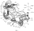
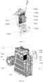
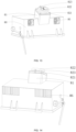
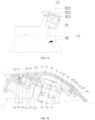
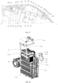
- FIG. 1 is a perspective view of the electric motorcycle from the back to the front.
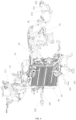
- FIG. 2 is another perspective view of the electric motorcycle.
- an electric motorcycle 10 includes a frame 20, a front wheel 11, a rear wheel 12, a plurality of seats 13, a dashboard panel 14, a front suspension 31, a rear suspension 32, a vehicle cover 40, an electric motor 50, a battery pack 60, a controller 70, a charging device 80, a rear side-box assembly 90, a braking system 100, a front cowling 43, and a steering system 110.
- the battery pack 60 and the controller 70 are respectively arranged on the frame 20.
- the battery pack 60 supplies electric power for the controller 70 and the motor 50.
- the controller 70 controls the electric motor 50 to drive the rear wheel 12 to rotate.
- the charging device 80 is arranged on the frame 20.
- the charging device 80 is connected to the public supply system by wires, so as to convert the AC from the public supply system into DC to charge the battery pack 60.
- the battery pack 60, the controller 70 and the charging device 80 are arranged in sequence along the height direction of the frame 20, and the vertical dimension from the charging device 80 to the dashboard panel 14 is less than the vertical dimension from the battery pack 60 to the dashboard panel 14.
- the battery pack 60, the controller 70 and the charging device 80 are arranged on the frame 20 adjacent to the front wheel 11.
- the position for placing the battery pack 60, controller 70 and charging device 80 on the frame corresponds to the position of the fuel tank on the fuel motorcycle.
- the electric motorcycle 10 is more compact.
- the center of gravity of electric motorcycle 10 is concentrated on the half adjacent to the front wheel 11, and the center of gravity is lower.
- the electric motorcycle can run stably and safely even at a maximum speed of 120 km/h.
- the volume of electric motorcycle 10 can be smaller and the wind resistance can be reduced, thereby improve the controllability of electric motorcycle while achieving high endurance.
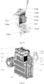
- the battery pack 60 includes a battery 61 and a battery case 62.
- the battery 61 is arranged in the battery case 62.
- the battery case 62 is connected to the frame 20.
- the battery case 62 enhances the strength of the frame 20 and improves the firmness of the electric motorcycle 10.
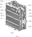
- the battery case 62 includes a body case 621 and a plurality of side plates 622, which are fixed to the body case 621 by screws.
- the side plates are provided with a plurality of ribs 6221.
- the ribs 6221 increase the surface area of the battery case 62 and improve the heat dissipation of the battery pack 60. At the same time, the strength of the battery case 62 is enhanced, thereby improving the safety of the electric motorcycle 10.
- the bottom of the body case 621 is provided with a plurality of indentations 6211.
- the number of indentations 6211 is three.
- a cushion block 6212 having a plurality of holes is arranged between two adjacent indentations 6211.
- the upper end surface of the cushion block 6212 is flat with the upper end surface of the indentation 6211.
- the battery 61 is arranged in the body case 621 and is supported by the indentations 6211 and the cushion blocks 6212.
- the electric motorcycle is provided with a cooling air passage 63 for cooling the battery pack 60.
- a cooling air passage 63 is a passage formed around the battery pack 60 and a space between the vehicle cover 40 and the battery pack 60. The heat can be quickly dissipated from the battery pack 60 via the cooling air passage 63, which can make the working temperature of the battery pack within the preset range and reduce the electricity loss of battery pack when the electric motorcycle is running at high speed, thereby ensuring the safety and endurance of the electric motorcycle.
- the battery pack 60 is also be cooled down by a radiator 71a.
- Water-cooling can make the battery pack 60 rapidly cooled down at high temperatures, and the battery pack 60 can work normally and efficiently.
- the radiator 71a includes a water tank 711a, a radiating pipe 712a connected to the water tank 711a, and a water pump 713a in fluid communication with the radiating pipe 712a.
- the radiating pipe 712a is partially arranged on the battery pack 60.
- the radiating pipe 712a includes a first branch pipe 7121a, a second branch pipe 7122a and a third branch pipe 7123a.
- One end of the first branch pipe 7121a is in fluid communication with the outlet of the water tank 711a, and the other end is in fluid communication with the inlet of the water pump 713a.
- One end of the second branch pipe 7122a is in fluid communication with the outlet of the water pump 713a, and the other end is in fluid communication with the inlet of the battery pack 60.
- the third branch pipe 7123a is in fluid communication with the outlet of the battery pack 60, and the other end is in fluid communication with the return end of the water tank 711a, and the third branch 7123a is partially fixed on the battery pack 60.
- a plurality of radiating fins 7112a are arranged on the side wall of water tank 711a.
- the radiating fins 7112a increases the contact area between battery case and air to improve heat dissipation effect.
- the radiator 71a also includes a radiating fan 7113a, which is arranged on one side of the water tank 711a.
- the fan bracket 7114a is fixed on the water tank 711a by screws, and the radiating fan 7113a is arranged on the fan bracket 7114a.
- the air inlet of the radiating fan 7113a faces toward the seats 13, and the air outlet of the radiating fan 7113a faces toward the dashboard panel 14.
- the air flow generated by the radiating fan 7113a flows towards the water tank 711a, which improves heat dissipation efficiency of the water tank 711a and keeps the coolant in the water tank 711a at a low temperature, thereby improving the cooling efficiency of the coolant for the battery pack 60 and further improving the safety of the electric motorcycle 10 at high speed.
- the radiator 71a also includes an auxiliary water tank 714a arranged on the frame 20.
- the auxiliary water tank 714a is in fluid communication with a liquid delivery pipe 7144a, and the liquid delivery pipe 7144a is in fluid communication with the water tank 711a.
- a negative pressure is formed in the water tank 711a when the volume of the coolant in the water tank 711a decreases.
- the coolant in the auxiliary water tank 714a can be delivered to the water tank 711a by the liquid delivery pipe via the negative pressure.
- the auxiliary water tank 714a can keep the coolant content in the water tank 711a unchanged, maintains the cooling performance of the coolant to the battery pack 60, and ensures the safety of the electric motorcycle 10 when driving.
- the controller 70 is positioned between the charging device 80 and the battery pack 60.
- the controller is provided with a wire connector, which is connected to the electric motor through cables.
- the controller 70 is arranged on the battery case 62, and the controller 70 is positioned at one end of the battery case 62 adjacent to the dashboard panel 14.
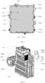
- An installation portion 623 having a groove is arranged on the battery case 62. The controller is installed in the groove and fixed on the battery case 62 by screws.
- the frame 20 is provided with a cooling device 71b for cooling the controller 70.
- the cooling device 71b includes a cooling box 711b, a coolant pipe 712b in fluid communication with the cooling box 711b, and a pump body 713b in fluid communication with the coolant pipe 712b.
- the coolant in the coolant pipe 712b is also flows through the controller 70.
- the coolant pipe 712b includes a first branch pipe 7121b, a second branch pipe 7122b and a third branch pipe 7123b. One end of the first branch pipe 7121b is in fluid communication with the outlet of the cooling box 711b, and the other end is in fluid communication with the inlet of the pump body 713b.
- One end of the second branch pipe 7122b is in fluid communication with the outlet of the pump body 713b, and the other end is in fluid communication with the inlet of the controller 70.
- the third branch pipe 7123b is in fluid communication with the outlet of the controller 70, and the other end is in fluid communication with the return end of the cooling box 711b, and the third branch pipe 7123b is partially fixed on the battery pack 60.
- the side wall of the cooling box 711b also includes a plurality of radiating fins 7112b and a radiating fan 7113b.
- the radiating fan 7113b is used to cooling the cooling box 711b.
- the radiating fan 7113b and the radiating fins 7112b is arranged on the same side.
- the radiating fan 7113b is installed on the cooling box 711b by a fan bracket 7114b to cool the cooling box 711b, which improves the heat dissipation efficiency of the radiating fins 7112b.
- the air inlet of the radiating fan 7113b faces toward the seats 13, and the air outlet of the radiating fan 7113a faces toward the dashboard panel 14. After the radiating fan 7113b is started, the airflow generated flows from the side adjacent to the seats 13 to the side far away from the seats 13, so as to avoid hot air blowing directly to the driver.
- the cooling device 71b may further include an auxiliary water tank 714b arranged on the frame 20.
- the auxiliary water tank 714b is in fluid communication with a liquid delivery pipe 7144b, and the liquid delivery pipe 7144b is in fluid communication with the cooling box 711b.
- a negative pressure is formed in the cooling box 711b when the amount of coolant in the cooling box 711b decreases.
- the coolant in the auxiliary water tank 714b is delivered to the cooling box 711b by the liquid delivery pipe under the negative pressure of the cooling box 711b.
- the auxiliary water tank 714b can keep the coolant content in the cooling box 711b unchanged, maintains the cooling performance of the coolant to the battery pack 60, and ensures the safety of the electric motorcycle 10 when driving.
- the coolant in the coolant pipe 712b also flows through the battery pack 60.
- a plurality of cooling fans 72 are arranged on the frame 20.
- the air inlets of the cooling fans 72 face toward the rear wheel 12, and the air outlets of the cooling fans 72 face toward the front wheel 11.
- the air from the air outlets blows to the controller 70.
- the cooling fans 72 conduct air-cooling for the controller 70.
- the air inlet faces toward the rear wheel 12, which makes the air flow towards the front wheel 11 to avoid hot air blowing directly to the driver.
- the charging device 80 is arranged on the frame 20, and the charging device 80 is positioned on the frame 20 adjacent to the seats 13.
- the charging device 80 is provided with a charging connector 81, which faces toward the opposite direction of the front cowling 141.
- the charging connector 81 is positioned on the side of the charging unit 80 away from the controller 70, and is positioned on the side of the seats 13 toward the dashboard panel 14.
- the charging device 80 is provided with a charging connector 81, the charging connector 81 is provided with a charging interface 811, and the opening of the charging interface 811 faces toward the seats 13.
- the axis along the length direction of the charging connector 81 is defined as a straight line L1
- the line connecting the center point of the front wheel and the center point of the rear wheel is defined as a straight line L2
- an angle is defined by a straight line L1 and the straight line L2, and the angle is in the range from 30° to 60°.
- the charging connector 81 is detachably connected to a sealing plug 82.
- the sealing plug 82 includes a plug body 821 and a plug cap 822.
- the plug cap 822 is provided with a connecting rope 823, and one end of the connecting rope is connected to the charging connector 81 or the plug body 821.
- the plug body 821 is detachably connected to the charging connector 81.
- the plug cap 822 is partially inserted into the plug body 821.
- the plug cap 822 is provided with a ring groove on the side facing the charging connector 81. After the plug cap 822 is inserted into the plug body 821, the ring groove covers the side wall of the plug body 821, and the ring groove and the plug body 821 extrude each other to form a seal.
- the vehicle cover 40 is provided with a charging port 481 corresponding to the charging connector 81.
- One end of the charging port 481 extends toward the charging connector 81, and a shutter 482 is arranged on the end of the charging port 481.
- the middle of the shutter 482 is provided with a shutter opening 4821, and the position of the shutter opening 4821 corresponds to the charging connector 81.
- the shutter 482 is provided with at least one water leakage hole 4822, and the water leakage hole 4822 is opened at the lowest point of the shutter 482 along the motorcycle height direction.
- the end face of the charging connector 81 facing toward the charging port 481 is provided with a plug body 821, and the end face of the plug body 821 away from the charging connector 81 is at least partially passes through the shutter opening 4821 along the axis direction of the charging connector 81.
- connection surface between the charging connector 81 and the external connector at least partially passes through the shutter opening 4821 along the axis direction of the charging connector 81.
- the vehicle cover 40 is equipped with a charging port cover mounting part 483 corresponding to the charging connector 81.
- the charging port cover mounting part 483 is positioned at the side of the seats 13 facing toward the front wheel 11, and the charging port cover mounting part 483 is provided with two shaft mounting parts 4831 extending toward the front.
- the vehicle cover 40 is connected to a charging port cover 83 that closes the charging port 481.
- the end face of the charging port cover 83 is smoothly incorporated into the end face of the vehicle cover 40.
- the locking structure 84 is connected to the vehicle cover 40.
- the charging port cover 83 is turned and opened toward the dashboard panel 14.
- the charging port cover 83 is arranged on the charging port cover mounting part 483.
- the locking structure 84 includes a connecting rod 841, a rotating shaft 842, a button 843 and a torsion spring 844.
- the connecting rod 841 is connected to one side of the charging port cover 83.
- the rotating shaft 842 is connected to the connecting rod 841 and is rotatably arranged on the vehicle cover 40.
- the torsion spring 844 is arranged on the rotating shaft 842, and one end of the torsion spring is connected to the connecting rod 841, and the other end is connected to the vehicle cover 40. The lock of the charging port cover 83 is released after the button 843 is pressed.
- the connecting rod 841 rotates around the rotating shaft 842 under the action of the restoring force of the torsion spring 844, and the charging port cover 83 opens automatically.
- the button 843 is arranged on the charging port cover 83, and an elastic element 844 is arranged between the button 843 and the charging port cover 83.
- the elastic element 844 is a compression spring.
- the connecting rod 841 bents toward the charging connector 81.
- the connecting rod 841 includes a first segment 8411 connected to the rotating shaft 842 and a second segment 8412 connected to the charging port cover 83.
- the length of the first segment 8411 is greater than or equal to the distance between the edge of the shutter opening 4821 adjacent to the front wheel 11 and the rotation center of the rotating shaft 842.
- the second segment 8412 passes through the shutter opening 4821 and is connected to the charging port cover 83.
- two ends of the rotating shaft 842 are rotatably arranged on the rotating shaft mounting part 4831.
- a damping member is disposed on the connection between the rotating shaft 842 and the vehicle cover 40.
- the charging port cover 83 includes a cover plate 831 and a bottom plate 832.
- a cavity is defined by the cover plate 831 and the bottom plate 832.
- a first recess 8321 is defined at one end of the bottom plate 832 facing toward the dashboard panel 14.
- a second recess 8322 is defined at one end of the bottom plate 832 facing toward the seats 13.
- the connecting rod 841 is connected to the first recess 8321, and the button 843 is arranged within the second recess 8322.
- the cover plate 831 defines a pressing hole 8211 for the button 843 to pass through.
- the pressing surface of the button 843 is flush with the surface of the cover plate 831, or is sunken from the surface of the cover plate 831 to the bottom plate 832.
- the outer edge of the button 843 is provided with a limiting convex ring 8431, which is abutted against with the cover plate 831 under the thrust of the elastic element 844 to prevent dust and impurities from entering into the second concave part 8322 through the gap between the pressing surface of the button 843 and the cover plate 831.
- the sealing plug 82b is a part of the charging port cover 83b.
- the sealing plug 82b is separated from the charging connector 81b to facilitate charging when the charging port cover 83b is opened.
- a plurality of cooling fans 85 is arranged on the charging device 80.
- the air inlet of the cooling fans 85 faces toward the seats 13, and the air outlet of the cooling fans 85 faces toward the interior of the charging device 80.
- the charging device 80 includes at least two cooling fans 85, and the two cooling fans 85 is symmetrically arranged on the charging device 85 respective to the line connecting the center point of the front wheel 11 and the center point of the rear wheel 12.
- the charging device 80 is provided with a plurality of air outlets 86 oriented toward the dashboard panel 14.
- the cooling fans 85 cool down the charging device 80 by air to improve the safety of the motorcycle during charging.
- the air outlet 86 faces toward the dashboard panel 14 to avoid hot air blowing directly to the driver.
- the charging device 80 is also be cooled down by a water-cooling device 71c.
- the water-cooling device 71c includes a water tank 711c, a cooling pipe 712c connected to the water tank 711c, and a water pump 713c connected to the cooling pipe 712c.
- the coolant in the cooling pipe 712c flows through the charging device 80, and the cooling pipe 712c is partially arranged on the charging device 80.
- the cooling pipe 712c includes a first pipeline 7121c, a second pipe line 7122c and a third pipeline 7123c. One end of the first pipeline 7121c is connected to the outlet of the water tank 711c, and the other end is connected to the inlet of the water pump 713c.
- One end of the second pipeline 7122c is in fluid communication with the outlet of the water pump 713c, and the other end is in fluid communication with the inlet of the charging device 80.
- the third pipeline 7123c is in fluid communication with the outlet of the charging device 80, and the other end is in fluid communication with the return end of the water tank 711c, and the third pipeline 7123c is partially fixed on the battery pack 60.
- the side wall of water tank 711c is also provided with a plurality of radiating fins 7112c and a radiating fan 7113c.
- the radiating fan 7113c is used to cooling the water tank 711c.
- the radiating fan 7113c and the radiating fins 7112c is arranged on the same side.
- the radiating fan 7113c is installed on the water tank 711c by a fan bracket 7114c to cool down the water tank 711c, which improves the heat dissipation efficiency of the radiating fins 7112c.
- the air inlet of the radiating fan 7113c faces toward the seats 13, and the air outlet of the radiating fan 7113a faces toward the dashboard panel 14. After the radiating fan 7113c is started, the airflow generated flows from the side adjacent to the seats 13 to the side far away from the seats 13, so as to avoid hot air blowing directly to the driver.
- the water-cooling device 71c also includes an auxiliary water tank 714c arranged on the frame.
- the auxiliary water tank 714c is fixed on the frame 20 or the battery case 62, and is in fluid communication with the water tank 711c through pipelines.
- the water tank 711c draws coolant from the auxiliary water tank 714c via negative pressure.
- the coolant in the auxiliary water tank 714c is automatically replenished to the water tank 711c to maintain the heat dissipation performance of the water cooling device 71c to the charging device 80.
- a cooling device 71d for cooling the electric motor 50 and the controller 70 is arranged on the electric motorcycle.
- the cooling device 71d includes a cooling box 711d, a coolant pipe 712d in fluid communication with the cooling box 711d and a water pump 713d in fluid communication with the coolant pipe 712d.
- the coolant pipe 712d is partially disposed on the battery pack 60.
- the coolant pipe 712d includes a first branch pipe 7121d, a second branch pipe 7122d, a third branch pipe 7123d and a fourth branch pipe 7124d.
- One end of the first branch pipe 7121d is in fluid communication with the outlet of the cooling box 711d, and the other end is in fluid communication with the inlet of the water pump 713d.
- One end of the second branch pipe 7122d is in fluid communication with the outlet of the water pump 713, and the other end is in fluid communication with the inlet of the controller 70.
- the third branch pipe 7123d is in fluid communication with the outlet of the controller 70, and the other end is in fluid communication with the inlet of the motor 50.
- One end of the fourth branch pipe 7124d is in fluid communication with the outlet of the electric motor 50, and the other end is in fluid communication with the return end of the cooling box 711d.
- the fourth branch pipe 7124d is partially fixed on the battery pack 60.
- the coolant in the coolant pipe 712d may first flow through the electric motor 50, then flow through the controller 70, and then return to the cooling box 711d.
- the side wall of water tank 711d is also provided with a plurality of radiating fins 7112d and a radiating fan 7113d.
- the radiating fan 7113d is used to cooling the water tank 711d.
- the radiating fan 7113d and the radiating fins 7112d are arranged on the same side.
- the radiating fan 7113b is installed on the cooling box 711d by a fan bracket 7114d to cool the cooling box 711d, which improves the heat dissipation efficiency of the radiating fins 7112d.
- the air inlet of the radiating fan 7113d faces toward the seats 13, and the air outlet of the radiating fan 7113a faces toward the dashboard panel 14. After the radiating fan 7113d is started, the airflow generated flows from the side adjacent to the seats 13 to the side far away from the seats 13, so as to avoid hot air blowing directly to the driver.
- the cooling device 71d also includes an auxiliary water tank 714d arranged on the frame.
- the auxiliary water tank 714d is fixed on the frame 20 or the battery case 62, and is in fluid communication with the cooling box 711d through pipelines.
- the cooling box 711d draws coolant from the auxiliary water tank 714 through negative pressure.
- the coolant in the auxiliary water tank 714d is automatically replenished to the cooling tank 711d to maintain the heat dissipation performance of the water-cooling device 71 to the electric motor 50.
- the auxiliary water tank 714d includes an auxiliary water tank body 7141d, water-adding channel7142d, and an auxiliary water tank cap 7143d.
- the auxiliary water tank body 7141 is mounted on the frame 20 by bolts.
- the water-adding channel 7142d is in fluid communication with the auxiliary water tank body 7141d.
- the water-adding channel 7142d is a curved structure, which is convenient for adding water.
- the auxiliary water tank cap 7143d is detachably connected to the end of the water-adding channel 7142 far away from the auxiliary water tank body 7141d to close the auxiliary water tank body 7141d.
- the auxiliary water tank cap 7143d and the auxiliary water tank body 7141d is connected by threads.
- the auxiliary water tank 714d is fixed to the frame 20. In other embodiments, the auxiliary water tank 714d is fixed to the battery case 62. The auxiliary water tank 714d is positioned on one side of the battery case 62, and the cooling box 711d is positioned on the other side of the battery case 62. In other embodiments, the auxiliary water tank 714d and the cooling box 711d is positioned on the same side of the battery case 62. The auxiliary water tank 714d is in fluid communication with the cooling box 711d through a water-replenishing pipe 7144d fixed on the battery case 62.
- the water-replenishing pipe 7144d is fixed on the frame 20.
- the cooling box 711d is provided with a water-replenishing port in fluid communication with the water-replenishing pipe 7144d.
- the water in the auxiliary water tank 714d will flow into the water tank 711 through the water-replenishing pipe 7144d when the water level in the cooling box 711d is below the preset value.
- the electric motor 50 is also be cooled down by a water-cooling device 71e.
- the water-cooling device 71e includes a water tank 711, a cooling pipe 712e in fluid communication with the water tank 711e, and a water pump 713e in fluid communication with the cooling pipe 712e.
- the coolant in the cooling pipe 712e flows through the electric motor 50.
- the cooling pipe 712e includes a first branch pipe 7121e, a second branch pipe 7122e and a third branch pipe 7123e. One end of the first branch pipe 7121e is in fluid communication with the outlet of the water tank 711e, and the other end is in fluid communication with the inlet of the water pump 713e.
- One end of the second branch pipe 7122e is in fluid communication with the outlet of the water pump 713e, and the other end is in fluid communication with the inlet of the electric motor 50.
- the third branch pipe 7123e is in fluid communication with the outlet of the electric motor 50, and the other end is in fluid communication with the return end of the cooling box 711d, and the third branch pipe 7123e is partially fixed on the battery pack 60.
- the side wall of water tank 711e is also be provided with a plurality of radiating fins 7112e and a radiating fan 7113e.
- the radiating fan 7113e is used to cool the water tank 711e.
- the radiating fan 7113e and the radiating fins 7112e are arranged on the same side.
- the radiating fan 7113c is installed on the water tank 711e by a fan bracket 7114e to cool down the water tank 711e, which improves the heat dissipation efficiency of the radiating fins 7112e.
- the air inlet of the radiating fan 7113e faces toward the seats 13, and the air outlet of the radiating fan 7113a faces toward the dashboard panel 14. After the radiating fan 7113e is started, the airflow generated flows from the side adjacent to the seats 13 to the side far away from the seats 13, so as to avoid hot air blowing directly to the driver.
- the water-cooling device 71e also includes an auxiliary water tank 714e fixed on the frame 20 or the battery case 62.
- the auxiliary water tank 714e is in fluid communication with the water tank 711e by a pipeline.
- the coolant is pumped from the auxiliary water tank 714e into the water tank 711e through negative pressure.
- the coolant in the auxiliary water tank 714e is automatically replenished to the water tank 711e to maintain the heat dissipation performance of the water-cooling device 71e to the electric motor 50.
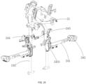
- the frame 20 includes a front frame 21 adjacent to front wheel 11 and rear frame 22 adjacent to rear wheel 12.
- a plurality of front bumpers 241a is mounted on the front frame 21.
- the number of the front bumpers 241a is greater than or equal to two.
- Two front bumpers 241a are symmetrically arranged on two sides of the battery housing 62.
- the front bumpers 241a are straight bar, which reduces the wind resistance of the electric motorcycle at high speed, and improves the controllability and safety of the electric motorcycle.
- the front bumpers 241a are provided with a buffer member with an elastic structure. In other embodiments, the front bumpers 241a are provided with a hydraulic telescopic rod buffer structure or a pneumatic telescopic rod buffer structure.
- each front bumper 241b includes a tube body 2411b and a rod body 2412b connected to the frame 20.
- a cavity is defined inside the tube body 2411b, and the rod body 2412b is partially inserted into the cavity.
- a buffer spring 2413b is also inserted into the cavity.
- One end of the buffer spring 2413b is connected to the rod body 2412b.
- the buffer member 242b is coupled to the other end of the rod body 2412b.
- At least two fixing rods 243 is mounted on the front frame 21.
- One end of the fixing rod 243 is mounted on the front frame 21 by a connector 244, and the other end is connected to the battery case 62.
- the front bumper 241a is connected to the fixing rod 243 by connecting blocks 2431, which is a part of the fixing rod 243 and symmetrically arranged on two sides of the battery pack 60. Therefore, the pressure from the front bumpers 241a to the battery pack 60 can be transferred to the whole frame 20 when the front bumpers 241a are impacted.
- a battery bumper 245 for protecting the battery case 62 from impacting is mounted on the front frame 21.
- the battery bumper 245 includes a first bumper body 2451a, a first connector 2451b connected to the first bumper body 2451a, a second bumper body 2451c and a second connector 2451d connected to the second bumper body 2451c.
- the first connector 2451b and the second connector 2451d are staggered and connected by screws.
- the first bumper body 2451a is connected to one side of the frame, and the second bumper body 2451c is connected to the other side of the frame 20.
- the front bumper 241a is connected to one side of the connection block 2431 by screws, and the battery bumper 245 is connected to the other side of the connection block 2431 by screws.
- the battery bumper 245 is arranged between the two connecting blocks 2431.
- the axis of the battery bumper 245 is staggered with the axis of the front bumper 241a, which improves the strength between the fixing rods 243 and prevents the deformation of the fixing rods 243 due to the impact force on the front bumpers 241a.
- the outer wall of the body case 621 is provided with a plurality of connecting lugs 625 with a shaft hole 6251.
- the battery case 62 is connected to the frame 20 by the connecting lugs 625.
- the side of the battery case 62 adjacent to the front wheel 11 is connected to the front frame 21, and the side of the battery housing 62 adjacent to the rear wheel 12 is connected to the rear frame 22.
- a plurality of connection seats with a shaft hole is arranged on the outer wall of the battery case 62. Further, the connection seats are an arc-shaped bulges formed on the edge of the body case 621, and the shaft hole penetrates the bulge.
- the body case 621 is provided with a first connection seat 624a, a second connection seat 624b, a third connection seat 624c, a fourth connection seat 624d, a fifth connection seat 624e, a sixth connection seat 624f and a seventh connection seat 624g.
- the first connection seat 624a is positioned at the top of the battery case 62.
- the second connection seat 624b is positioned at the side of the battery case 62 facing toward the front wheel 11.
- the third connection seat 624c is positioned at the side of the battery case 62 facing toward the rear wheel 12 and at the edge of the battery case 62.
- the fourth connection seat 624d and the fifth connection seat 624e are both positioned at the side of the battery housing 62 toward the rear wheel 12.
- Two first connection seats 624a, two second connection seats 624b, two third connection seats 624c, two fourth connection seats 624d, two fifth connection seats 624e, two sixth connection seats 624d and two seventh connection seats 624e are symmetrically positioned on the battery case 62.
- the first connection seats 624a and the second connection seats 624b are connected to the front frame 21 with shaft and hole fit.
- the third connection seats 624c and the fourth connection seats 624d are connected to the rear frame 22 with shaft and hole fit.
- the seventh connection seats 624g are connected to the fixing rods 243 with shaft and hole fit.
- the battery case 62 is connected to a kickstand 25.
- the kickstand 25 is connected to a middle brace 261 and a diagonal brace 262.
- the kickstand 25 includes a bracket 251 and a mounting racks 252.
- the bracket 251 is fitted with the bottom surface of the battery case 62.
- a bending portion connected to the battery case 62 was defined by bending the two ends of the bracket 251.
- the bending portion 2511 is fitted with the battery case 62.
- One end of the bracket 251 facing toward the rear wheel 12 is hinged with the middle brace 261.
- Two mounting racks 252 is respectively mounted on the two sides of battery case 62.
- the mounting racks 252 is extended follow the edge contour of the bending portion 2511.
- Each mounting rack 252 is provided with a diagonal brace fixing part 2521, which is arranged obliquely against the side surface of the battery case 62, and the diagonal brace fixing part 2521 is hinged with the diagonal brace 262.
- the middle brace 261 is connected to the fifth connection seats 624e.
- the middle brace 261 includes two symmetrically arranged support rods 2611, one middle deflector rod 2612 and a first tension spring 2613.
- the support rods 2611 is arranged below the bracket 251.
- a reinforcing shaft 2614 is connected between the support rods 2611.
- the middle deflector rod 2612 is connected to one of the two support rods 2611.
- a connection rib 2616 is connected between the support rod 2611 and the deflector rod 2612.
- One end of the first tension spring 2613 is connected to the support rod 2611, and the other end is connected to the bracket 251.
- the diagonal brace 262 includes a diagonal brace hinge 2621, a diagonal brace 2622, and a second tension spring 2623.
- the diagonal brace hinge 2621 is a part of the diagonal brace 2622, one end of which is hinged with the diagonal brace fixing part 2521.
- the diagonal brace fixing part 2521 is inclined outwards, and the diagonal brace hinge 2621 and the diagonal brace 2622 is also inclined outwards.
- One end of the second tension spring 2623 is connected to the diagonal brace 2622, and the other end is connected to the bracket 251.
- the frame 20 is also provided with an alarm light mounting seat 273.
- the alarm lamp mounting base 273 is provided with an alarm lamp telescopic rod 2731.
- the alarm lamp 2731a is arranged on the alarm lamp telescopic rod 2731.
- the rear suspension 32 includes a rear fork 320.
- the motor is arranged on the rear fork 320.
- One end of the rear fork 320 is connected to the rear wheel 12, and the other end is connected to the electric motor 50.
- the electric motor 50 is arranged at the end away from the rear wheel 12.
- the electric motor 50 is associated with the rear wheel 12 through a timing belt 41.
- the electric motor 50 can move synchronously with the rear fork 320, and the tightness of the timing belt 51 remains unchanged.
- the rear fork 320 includes two symmetrically arranged support plates 321, and the electric motor 50 is arranged between the two support plates 321.
- the rear fork 320 is provided with an electric motor connecting shaft 323.
- the seventh connection seats 624g is arranged on the battery case 62.
- the rear fork 320 is moveably connected to the seventh connection seats 624g by the electric motor connecting shaft 323.
- each support plate 321 is provided with a connection chute 3212a at the same position.
- a rear wheel connecting shaft 121 is arranged on the rear wheel 12 through a bearing.
- One end of the rear wheel connecting shaft 121 is connected to the connecting chute 3212a on the one support plate 321, and the other end is connected to the connecting chute 3212a on the other support plate 321.
- One end of the two support plates 321 with a connecting chute 3212a is connected by a rear wheel connecting shaft 121, and the other end is connected by a electric motor connecting shaft 323, and the electric motor 50 is arranged between two support plates 321.
- Each support plate 321 includes an electric motor connecting part 3211 connected to the electric motor connecting shaft 323 and a rear wheel connecting part 3212 connected to the connecting chute 3212a.
- the electric motor 50 is connected to the electric motor connecting part 3211.
- the electric motor 50 is positioned between two symmetrically arranged electric motor connecting parts 3211.
- the electric motor connecting shaft 323 may also connected to the battery case 62.
- a plurality of connecting lugs are arranged on the battery case 62.
- the connecting lugs with a shaft hole are projections formed on the edge of the battery case 62, and symmetrically arranged on both sides of the battery case 62.
- the connecting lugs includes a first connecting lug 625a and a second connecting lug 625b.
- the electric motor connecting shaft 323 is inserted into the shaft hole of the first connecting lug 625a.
- the rear fork 320 is movably connected to the battery case 61 with a shaft and hole fit, which improves damping performance.
- the rear suspension 32 also includes a shock absorber 322, which includes a telescopic rod 3220 and a damping spring 3221 sleeved on the telescopic rod 3220.
- a shock absorber 322 which includes a telescopic rod 3220 and a damping spring 3221 sleeved on the telescopic rod 3220.
- One end of the telescopic rod 3220 is connected to the battery case 62, and the other end is connected to the rear fork 320.
- Two cross beam connecting parts 3211a connected to each other is symmetrically arranged on the two support plates 321.
- the two cross beam connecting parts 3211a are both connected to the telescopic rod 3220.
- the shock absorber 322 includes a telescopic rod 3220 and a damping spring 3221.
- One end of the telescopic rod 3220 is connected to the battery case 62, and the other end is connected to the rear fork 320, which can reduce the vibration generated during the movement of the rear fork 320 relative to the battery case 62 and reduce the vibration generated during the driving of the motorcycle.
- the telescopic rod 3220 includes a sleeve 3222 and a telescopic rod body 3223.
- a cavity 3222a is defined in the sleeve 3222.
- the sleeve 3222 is connected to the battery case 62.
- One end of the damping spring 3221 is connected to the sleeve 3222, and the other end of the damping spring 3221 is connected to the telescopic rod body 3223.
- the telescopic rod body 3223 is capable of sliding within the cavity 3222a.
- the telescopic rod body 3223 is provided with a shock pad 3223a positioned between the telescopic rod body 3223 and the sleeve 3222.
- the shock pad 3223a can further reduce the speed of the telescopic rod body moving back and forth relative to the sleeve 3222.
- a cavity 3222a is defined at one end of the sleeve 3222, and the other end of the sleeve 3222 is provided with a first spring stopper 3222b.
- One end of the telescopic rod body 3223 is moved in the cavity 3222a, and the other end is provided with a second spring stopper 3223b.
- One end of the damping spring 3221 is abutted against the first spring stopper 3222b, and the other end is abutted against the second spring stopper 3223b.
- the shock pad 3223a is connected to the second spring stopper 3223b.
- the shock pad 3223a and the telescopic rod body 3223 are positioned on the same side of the second spring stopper 3223b.
- the second spring stopper 3223b and the shock pad 3223a are both provided with concentrically arranged screw holes.
- One end of the telescopic rod body 3223 is capable of sliding back and forth in the cavity 3222a, and the other end is connected to the rear fork 320 by the screw hole.
- the telescopic rod 3220 is be provided with a flange gasket 3224.
- the flange gasket 3224 is clamped into the screw hole on the second spring stopper 3223b and the screw hole on the telescopic rod body 3223.
- One end of the telescopic rod body 3223 is capable of sliding in the cavity 3222a, and the other end is connected to a spring adjusting nut 3223c.
- the second spring stopper 3223b is provided with a damping limit groove, which is a groove formed on the second spring stopper 3223b.
- the spring adjusting nut 3223c is clamped into the damping limit groove.
- one end of the telescopic rod 3220 is connected to the battery case 62, and the other end is connected to the rear fork 320.
- the sleeve 3222 is connected to the battery case 62.
- the telescopic rod body 3223 is connected to the rear fork 320.
- a cavity 3222a is defined at one end of the sleeve 3222.
- the other end of the sleeve 3222 is provided with a first damping connecting shaft 3222c.
- the first damping connecting shaft 3222c is sleeved with a first connector 3222d, which is connected to the provided with 3222.
- the first damping connecting shaft 3222c is capable of rotating within the first connector 3222d, and the first damping connecting shaft 3222c is connected to the battery case 62.
- the first damping connecting shaft 3222c is connected to the second connecting lug 625b.
- the telescopic rod body 3223 is connected to the rear fork 320.
- One end of the telescopic rod body 3223 is capable of sliding within the cavity 3222a, and the other end of the telescopic rod body 3223 is provided with a second damping connecting shaft 3223e.
- the second damping connecting shaft 3223e is rotatably connected to a second joint 3223d.
- Each of the two support plates 321 is provided with a cross beam connecting parts 3211a having a damping rod connecting screw hole.
- the two cross beam connecting parts 3211a are connected to each other. Two ends of the second damping connecting shaft 3223e are respectively inserted into the two damping rod connecting screw hole of the cross beam connecting part 3211a.
- the telescopic rod body is rotatably connected to the rear flat by a shaft, thereby increasing the mobility of telescopic rod body.
- a rear fender 324 is arranged on the rear fork 320, the cross section of the rear fender 324 is arc-shaped towards the middle, and the rear fender 324 covers the rear wheel 12.
- One end of the rear fender 324 is connected to the rear fork 320, and the other end is suspended in midair and covers a part of the rear wheel 12.
- the middle of the rear fender 324 covers the rear wheel 12, and both sides extend towards two sides of the rear wheel 12.
- a driven wheel housing 3241 that covers a driven wheel 122 positioned on the rear wheel 12 is arranged on the rear fender 324.
- One end of the rear fender 324 is connected to the rear fork 320, and the other end extends along the edge of the rear wheel 12 and is arc-shaped.
- One end of the rear fender 324 is arc-shaped and suspended in midair. The other end is folded to form a fender connecting part 3242.
- the cross beam connecting part 3211a on the two symmetrically arranged support plates 52 is connected to the fender connecting part 3242 by screws.
- the rear fender 324 can prevent the mud and water rolled up by the rear wheel 12 from splashing onto the driver.
- the front cowling 43 can be detachably arranged on the front strut 211.
- the middle of the front cowling 43 protrudes in the direction of vehicle travel, and both sides bend towards the side opposite to the direction of vehicle travel, thus forming an arc-shaped surface on the front cowling 43.
- a headlight 152, at least two turn signal lights 153, a windscreen plate 154 and an on-board camera 159 are mounted on the front strut 211.
- the headlight 152 are arranged on the front cowling 43.
- Two of the turn signal lights 153 are symmetrically arranged on both sides of the headlight 152.
- the on-board camera 159 is arranged below the headlight 152, facing toward the direction of from the rear wheel 12 to the front wheel 11.
- the windscreen plate 154 is arranged on the front cowling 43.
- the contour of the windscreen plate 154 is fitted with the contour of the front cowling 43, so that the windscreen plate 154 forms an arc-shape similar to the front cowling 43.
- the contour of the windshield 155 is fitted with the contour of the windshield 154, so that the windshield 155 protrudes in the direction of vehicle travel, and both sides bend towards the side opposite to the direction of vehicle travel. That is to say, the middle of the windshield 155 protrudes along the direction of the rear wheel 12 toward the front cowling 43, forming an arched shape.
- the windshield 155 is arranged on the windshield plate 154, and the windshield plate 154 is connected to the windshield 155 by a lifting structure 1540.
- the windshield 155 can slide up and down on the windshield plate 154 driven by the lifting structure 1540.
- the windshield plate 154 for mixing the windshield 155 increase the strength of the windshield.
- the lifting structure 1540 includes a lifting motor 1541, a worm gear 1542, a worm 1543 and two connecting frames 1544.
- the output shaft of the lifting motor 1541 is connected to the worm 1543.
- the worm gear 1542 is provided with a worm gear drive rod 1542a connected to the connecting frame 1544.
- Two ends of worm gear drive rod 1542a are connected to the connecting frames 1544, and the lifting motor 1541 is arranged between the two connecting frames 1544.
- the power can be transmitted to the worm gear transmission rod 1542a when the output shaft of the lifting motor 1541 is perpendicular to the worm gear drive rod 1542.
- the cross section of the worm gear drive rod 1542 is square, and the worm gear drive rod 1542 is a metal straight rod.
- the connecting frame 1544 is provided with a windshield connecting rod 1544a, a rotating rod 1544b and a windshield hinge rod 1544c.
- One end of the rotating rod 1544b is connected to the worm gear drive rod 1542, and the other end is connected to the windshield connecting rod 1544a.
- the rotating rod 1544b can be driven by the worm gear drive rod 1542 to rotate.
- One end of the windshield hinge rod 1544c is rotatably connected to the vehicle head 15, and the other end is rotatably connected to the windshield hinge rod 1544.
- the worm gear drive rod 1542 can drive the windshield 155 to rotate.
- the steering system 110 are associated with the rear suspension 31 to control the rotation of the front wheel 11.
- the steering system includes a steering handle 111 and a pair of a grip assemblies 112 symmetrically arranged on both sides of the steering handle 111. The driver holds one of the grip assemblies 112 in each hand while driving.
- the grip assembly 112 includes a grip switch assembly 1121 and an electronic-controlled throttle 1122.
- the electronic-controlled throttle 1122 is a hollow rod body.
- the electronic-controlled throttle 1122 is sleeved on the steering handle 111.
- the output power of the electric motor 50T can be increased by turning electronic-controlled throttle 1122.
- Each grip assembly 112 also includes two grip counterbalance blocks 1123 and a thread insert 1124.
- the electronic-controlled throttle1122 is sleeved on the steering handle 111.
- the two grip counterbalance block 1123 are respectively arranged on two ends of the steering handle 111.
- the grip counterbalance block 1123 is abutted against the electronic-controlled throttle 1122.
- a through hole is defined at the axial position of the grip counterbalance block 1123.
- the thread insert 1124 is inserted into the through hole.
- the thread insert 1124 is abutted against the grip counterbalance block 1123, which is abutted against the electronic-controlled throttle 1122, so as to fix the electronic-controlled throttle 1122 on the steering handle 111.
- One end of the electronic-controlled throttle 1122 is connected to the grip counterbalance block 1123, and the other end is connected to the switch assembly 1121.
- the electronic-controlled throttle 1122 is equipped with a grip sleeve 11221, which is abutted against the switch assembly 1121.
- the steering handle 111 is also provided with a hand-operated brake 351, which is associated with the brake system 100.
- An x-axis is defined as the length direction of the electric motorcycle, and a y-axis is defined as the height direction of the electric motorcycle.
- the projection of the first operation area on a cutting plane coordinate system xoy is in the scanning area of - 45-0°.
- the girp assembly 112 is provided with a switch assembly 1121, and a plurality of buttons are arranged in different areas of the switch assembly 1121.
- the switch assembly 1121 is provided with a first operation area, a second operation area, a third operation area and a fourth operation area.
- An x-axis is defined as the length direction of the electric motorcycle, and a y-axis is defined as the height direction of the electric motorcycle.
- the projection of the first operation area on a cutting plane coordinate system xoy is in the scanning area of -45-0°.
- the projection of the second operation area on a cutting plane coordinate system xoy is in the scanning area of 0- 45°.
- the projection of the third operation area on a cutting plane coordinate system xoy is in the scanning area of 45- 90°.
- the projection of the fourth operation area on a cutting plane coordinate system xoy is in the scanning area of 90-135°.
- the first operation area is provided with a horn button 1121a and turn signal light button 1121b.
- the second operation area is provided with a power assisted pushing button 1121c and a shift button 1121d.
- the power assisted pushing button 1121c can realize the switching of forward gear and backward gear mainly by controlling the switching of forward and reverse rotation of electric motor 50.
- the third operation area is provided with a multi-function button, a loudspeaker button 1121g, and a loudspeaker circular broadcast button 1121j.
- the fourth operation area is provided with a high and low beam light on/off button 1121h.
- the multi-function button includes a lifting button 1121e and a switching button 1121f.
- the lifting button 1121e is provided with a concave portion.
- the switching button 1121f is partially inserted into the concave portion after the switching button moves toward the steering handle.
- the lifting button 1121e is capable of controlling the lifting of the windshield 154 when the switching button 1121f is inserted into the concave portion.
- the lifting button 1121e is capable of controlling the lifting of the alarm light when the switching button 1121f is detached from the concave portion.
- the lifting button 1121e is capable of controlling the lifting of the alarm lights when the switching button 1121f is inserted into the concave portion.
- the buttons with different frequency of use are arranged in different areas, which can increase the convenience of operation and facilitate the driver to remember the positions of buttons with different functions. Windshield can be raised and lowered according to different driving scenarios.
- the first operation area is also provided with a photographing button 1121i for controlling the on-board camera 159.
- the on-board camera is configured to capture photos during cruise.
- the vehicle cover 40 covers the most of the electric motorcycle 100. Gaps are defined between various components on the vehicle cover 40 to provide air flow to the inner wall of the vehicle cover, thereby cooling various components covered by the vehicle cover 40.
- the vehicle cover 40 includes a side cover 41, a upper cowling 42, a front cowling 43, a battery cover 44, a lower cowling 45, a front fender 46, a front shield 47, a charging device cover 48 and a rear fork cover 49. Gaps are defined between various components on the vehicle cover 40 to provide air flow to the interior of the vehicle cover, thereby cooling various components covered by the vehicle cover 40.
- the charging device cover 48 covers the charging device 80.
- the battery cover 44 is wrapped on the outside of the battery case 62, and the upper cowling 42 is positioned between the charging device cover 48 and the battery cover 44. One end of the battery cover 44 fits the upper cowling 43, and the other end fits the lower cowling 45.
- the front shield 47 is arranged between the front wheel 11 and the power battery 60. The front shield 47 is provided with a vent for air.
- the rear fork cover 49 covers the area of the rear suspension 32.
- the rear fork cover 49 is provided with one or more foot pedals 491, and the foot pedals 491 are provided with anti-skid grooves.
- the foot pedals 491 include an upper foot pedal 4911 and a lower foot pedal 4912.
- the upper foot pedal 4911 is covered with the lower foot pedal 4912.
- the anti-skid groove is arranged on the upper foot pedal 4911, and the lower foot pedal 4912 is connected to the rear fork cover 49.
- the rear fork cover 49 is at least provided with one or more foot pedals 491.
- the one or more foot pedals 491 include a inclined foot pedal 491 inclined to the rear fork cover 49.
- the foot pedal 491 is provided with a foot pedal connecting block 4913, which is connected to the rear fork cover 49.
- the rear fork cover 49 is provided with a plurality of pedal connecting slots 4914, and at least one pedal connecting slot 4914 has an inclined inner wall.
- the pedal connecting block 4913 is closely fitted with the side wall of the pedal connecting slot 4914.
- the foot pedal connecting block 4913 and the foot pedal connecting slot 4914 are both provided with a concentrically arranged foot pedal connecting through hole.
- the foot pedal connecting shaft 4915 is inserted into the foot pedal connecting through hole.
- the foot pedal connecting shaft 4915 is sleeved with a foot pedal reset member 4916.
- the foot pedal reset part 4916 is a torsion spring.
- two rear side-boxes 91 arranged on the frame include a box body 911 and a box cap 912.
- the two rear side-boxes 91 are respectively arranged at two sides of the electric motorcycle 100.
- the box body 911 and the vehicle cover 40 are integrated ⁇
- the frame 20 is provided with a rear tail cover/center guard plate, which is a part of the vehicle cover 40.
- the box body 911 is a part of the rear tail cover/center guard plate, and the box body 911 and the rear tail cover are integrated.
- the rear side-box and the vehicle cover are integrated, which can increase the aesthetics and the connection strength of the vehicle cover.
- the box body 911 includes a side-box cap 911a and a side-box liner 911b.
- the side-box inner 911b is placed inside the side-box cap 911a, and the contour of the he side box inner 911b is fitted with the contour of the side-box cap 911a.
- the side-box cover 912 comprises a side-box top cover 912c, a side-box cover inner plate 912b and a side-box cover cap 912a fitted with each other.
- the side-box cover inner plate 912b is positioned between the side-box top cover 912c and the side-box cover cap 912a.
- the box body 911 and the box cover 912 are movably connected to each other.
- One end of the box body 911 and one end of the box cap 912 are hinged by a rear side-box hinge 913, and the other ends are connected by a locking structure 914.
- the distance from the central point of the rear wheel 12 to the rear side -box hinge 913 is less than the distance from the central point of the rear wheel 12 to the locking structure 914.
- the box body 911 is provided with a box cover puller 915.
- One end of the box cover puller 915 is hinged with the box body 911, and the other end is hinged with the box cover 912.
- the box cover puller 915 will pull the box cover 912.
- a rear side-box containing cavity is defined on the box 911.
- An annular bulge 916 is formed along the circumferential wall of the rear side box containing cavity.
- the side-box cover 912 covers the annular bulge 916.
- the rear side-box hinges 913 and the side-box cover puller 915 are all arranged on the annular bulge 916.
- the locking member 914 is arranged on the annular bulge 916.
- the locking member 914 includes a drive member 9141, a plurality of locking members 9142, and a locating member 9143.
- the locating member 9143 is provided with a side-box locating opening 9143a, and the locking member 9142 moves back and forth in the side-box locating opening 9143a.
- the locking members 9142 are connected to the drive member 9141 by a locating member connecting piece 9144, and the locating member connecting piece 9144 is arranged around the annular bulge 256.
- the locating member 9143 is provided with an opening 9143b connected to the side-box locating opening 9143a.
- the drive member 9141 drives the locating member connecting piece 9144 to move back and forth.
- a drive member drives the locating member to enter the locating opening 9143a from the locating member opening 9143b, or enter the locating member opening 9143b from the locating opening 9143a.
- the side-box can be released and opened by the locking members.
- At least two rear bumpers 27 connected to the frame are arranged at two sides of the electric motorcycle 100.
- Two of the rear bumpers 27 are symmetrically arranged at two sides of the electric motorcycle 100.
- the two rear bumpers 27 are connected to each other by a rear bumper connection rod 28.
- Two ends of the connection rod 28 are respectively connected to the two rear bumpers 27.
- the rear bumpers 27 are provided with a rear bumper folding part 271, which is formed by bending the rear bumper 27.
- the distance of the rear bumper 27 along the width of the motorcycle is greater than the distance of the side box assembly 91 along the width of the motorcycle.
- the shortest distance between the end faces of the two rear bumpers 27 is greater than the shortest distance between the end faces of the two side-box assemblies 91.
- the rear bumper 27 is provided with a rear bumper buffer structure.
- the rear bumper buffer structure is a rear bumper buffer pad 272 at the end of the rear bumper 27.
- the rear bumper buffer pad 272 is a rubber pad.
- the buffer structure arranged on the rear bumper can protect the rear bumper body in case of emergency.
- the distance between the rear bumpers in a width direction is greater than the distance between the side-boxes, so that the rear bumpers can protect the side boxes.
- the alarm lamp mounting seat 273 is arranged on the rear bumpers 27, and the alarm lamp mounting seat 273 is connected to the rear bumper folding part 271 on the rear bumper.
- a trunk assembly 92 includes a trunk body 921 and a trunk cover 922 hinged by a trunk cover hinge 923.
- a trunk storage chamber for containing articles is defined in the trunk body 921.
- a trunk boss 924 is formed by extending the circumferential wall of the trunk storage chamber toward the axis of the trunk storage chamber.
- the trunk cover hinge 923 is arranged on the trunk boss 924.
- the trunk cover hinge 923 includes an articulated ring sleeve 9231.
- the trunk body 921 is provided with a trunk articulated shaft 9211 on which the articulated ring sleeve 9231 is sleeved.
- the trunk cover hinge 923 is also connected to the trunk cover 922.
- the trunk 92 is also provided with a trunk clearance lamp 926, which can reflect light.
- the trunk clearance lamp 926 is arranged on the side of the trunk body 921.
- the trunk 92 is also provided with a trunk backrest 927 connected to the side of the trunk body 921.
- the trunk backrest 927 is arranged on the side of the trunk 92 facing the back of the rider. That is to say, the trunk backrest 927 is concave toward the side of the trunk body 921.
- the side of the trunk 92 that contacts the trunk backrest 927 is curved. That is to say, the side of the trunk 92 that contacts the trunk backrest 927 is concave toward the center of the trunk 92.
- the trunk assembly 92 may also be removable to dispose a rear seat 93 and a rear seat backrest assembly 931.
- the rear seat backrest assembly 931 includes a backrest cushion 9311 and a backrest cushion bracket 9111 connected to the backrest cushion 9311.
- the backrest cushion bracket 9111 is connected to the frame 20.
- the backrest cushion bracket 9111 is connected to the cushion armrest 9313 and the backrest connecting frame 9314, wherein the number of the cushion armrest 9313 is equal to or greater than two.
- One end of each cushion armrest 9313 is connected to the backrest connecting frame 9314, and the other end is connected to the rear frame 22.
- the backrest cushion 9311 includes the backrest cushion body and the backrest cushion connecting plate 9311a, which is connected to the backrest cushion bracket 9111. That is to say, the backrest cushion connecting plate 9311a is connected to the backrest connecting frame 9314.
- One end of the backrest connecting frame 9314 is connected to the backrest connecting plate 9311a, and the other end is connected to the rear armrest trim cover 9314a.
- the rear wheel 12 includes a rear wheel connecting shaft 121, a hub 122, a pulley 123 and the timing belt 124.
- the rear wheel connecting shaft 121 passes through the rear wheel 12, so that the rear wheel 12 can rotate about the rear wheel connecting shaft 121.
- the pulley 123 is arranged on the hub 122.
- One end of the timing belt 124 is sleeved on the pulley 123, and the other end is sleeved on the output shaft of the electric motor 50.
- the surface of the pulley 123 is provided with a hard layer 1231, which is a part of the pulley 123.
- the thickness of the hard layer 1231 is 30 ⁇ m-60 ⁇ m or 40 ⁇ m-50 ⁇ m.
- the lightweight of the pulley improves the strength of the pulley and reduces the weight.
Landscapes
- Engineering & Computer Science (AREA)
- Mechanical Engineering (AREA)
- Chemical & Material Sciences (AREA)
- Manufacturing & Machinery (AREA)
- Chemical Kinetics & Catalysis (AREA)
- Electrochemistry (AREA)
- General Chemical & Material Sciences (AREA)
- Transportation (AREA)
- Power Engineering (AREA)
- Combustion & Propulsion (AREA)
- Life Sciences & Earth Sciences (AREA)
- Sustainable Development (AREA)
- Sustainable Energy (AREA)
- Electric Propulsion And Braking For Vehicles (AREA)
- Automatic Cycles, And Cycles In General (AREA)
- Axle Suspensions And Sidecars For Cycles (AREA)
Claims (14)
- Une motocyclette électrique (10) comprenant :un cadre (20) ;une roue avant (11) ;une roue arrière (12) ;une selle (13) agencée sur le cadre (20) ;un couvercle de véhicule (40) agencé sur le cadre (20) ;un panneau de tableau de bord (14) agencé sur le cadre (20) ;un contrôleur (70) ;un système de suspension comprenant une suspension avant (31) et une suspension arrière (32), la roue avant (11) étant reliée au cadre (20) par la suspension avant (31), et la roue arrière (12) étant reliée au cadre (20) par la suspension arrière (32) ;un moteur électrique (50), la roue arrière (12) étant reliée au moteur électrique (50) ;un bloc-batterie (60) agencé sur le cadre (20), le bloc-batterie (60) étant électriquement connecté au moteur électrique (50) ; etun dispositif de charge (80) agencé sur le cadre (20) et électriquement connecté au bloc-batterie (60), le dispositif de charge (80) comprenant un connecteur de charge (81) ;le bloc-batterie (60), le contrôleur (70) et le dispositif de charge (80) étant agencés en séquence selon la direction de hauteur du cadre (20), le bloc-batterie (60) et le dispositif de charge (80) étant positionnés sur le cadre (20) à proximité de la roue avant (11), et le contrôleur (70) étant agencé sur le bloc-batterie (60) ;la suspension arrière (32) comprenant un bras arrière (320) et un amortisseur (322) relié au cadre (20) par un arbre, le bras arrière (320) étant relié à la roue arrière (12) ;et le bloc-batterie (60) comprenant une batterie (61) et un boîtier de batterie (62), la batterie étant agencée à l'intérieur du boîtier de batterie (62), et le boîtier de batterie étant relié au cadre (20) ;caractérisé en ce quele moteur électrique (50) est agencé sur le bras arrière (320) ;le boîtier de batterie (62) est configuré pour renforcer la solidité du cadre (20) et améliorer la rigidité de la motocyclette électrique (10).
- La motocyclette électrique (10) selon la revendication 1, dans laquelle le cadre (20) comprend un cadre avant (21) adjacent à la roue avant (11) et un cadre arrière (22) adjacent à la roue arrière (12), le côté du boîtier de batterie (62) adjacent à la roue avant (11) étant relié au cadre avant (21), et le côté du boîtier de batterie (62) adjacent à la roue arrière (12) étant relié au cadre arrière (22).
- La motocyclette électrique (10) selon la revendication 1, dans laquelle le boîtier de batterie (62) comprend un corps de boîtier (621) et une pluralité de plaques latérales (622) fixées au corps de boîtier (621) par des boulons.
- La motocyclette électrique (10) selon la revendication 1, dans laquelle le fond du boîtier de batterie (62) est pourvu d'une pluralité d'indentations (6211), un bloc de coussinet (6212) étant agencé entre deux indentations (6211) adjacentes, la surface d'extrémité supérieure du bloc de coussinet (6212) étant au même niveau que la surface d'extrémité supérieure de l'indentation (6211), et une pluralité de trous étant définis sur chaque bloc de coussinet (6212).
- La motocyclette électrique (10) selon la revendication 2, dans laquelle le côté du boîtier de batterie (62) adjacent à la roue avant (11) est pourvu d'un premier siège de connexion (624a) et d'un deuxième siège de connexion (624b), et le côté du boîtier de batterie (62) adjacent au cadre arrière (22) est pourvu d'un troisième siège de connexion (624c) et d'un quatrième siège de connexion (624d), le premier siège de connexion (624a) et le deuxième siège de connexion (624b) étant reliés au cadre avant (21) par des arbres, et le troisième siège de connexion (624c) et le quatrième siège de connexion (624d) étant reliés au cadre arrière (22) par des arbres.
- La motocyclette électrique (10) selon la revendication 1, dans laquelle la motocyclette électrique (10) définit un conduit d'air de refroidissement (63) destiné au refroidissement du bloc-batterie (60).
- La motocyclette électrique (10) selon la revendication 6, dans laquelle le conduit d'air de refroidissement (63) est un passage formé autour du bloc-batterie (60) et un espace entre le couvercle de véhicule (40) et le bloc-batterie (60).
- La motocyclette électrique (10) selon la revendication 1, dans laquelle le contrôleur (70) est positionné à une extrémité du boîtier de batterie (62) adjacent au panneau de tableau de bord (14).
- La motocyclette électrique (10) selon la revendication 8, dans laquelle le boîtier de batterie (62) comprend une portion d'installation (623) définissant une rainure dans laquelle le contrôleur (70) est installé, et le contrôleur (70) est fixé sur le boîtier de batterie (62) par des vis.
- La motocyclette électrique (10) selon la revendication 1, dans laquelle un dispositif de refroidissement (71b) destiné au refroidissement du contrôleur (70) est agencé sur le cadre (20), le dispositif de refroidissement (71b) comprenant une boîte de refroidissement (711b), un tuyau de liquide de refroidissement (712b) en communication fluide avec la boîte de refroidissement (711b) et un corps de pompe (713b) en communication fluide avec le tuyau de liquide de refroidissement (712b), et le tuyau de liquide de refroidissement (712b) étant au moins partiellement agencé sur le contrôleur (70).
- La motocyclette électrique (10) selon la revendication 10, dans laquelle le contrôleur (70) est pourvu d'un canal de liquide de refroidissement de contrôleur ayant une entrée et une sortie ; le tuyau de liquide de refroidissement comprenant un premier tuyau dérivé (7121b) en communication fluide avec la sortie d'un réservoir d'eau (714b) et l'entrée du corps de pompe (713b), un deuxième tuyau dérivé (7122b) en communication fluide avec l'entrée du canal de liquide de refroidissement de contrôleur, et un troisième tuyau dérivé (7123b) en communication fluide avec la sortie du canal de liquide de refroidissement de contrôleur, le deuxième tuyau dérivé (7122b) étant en communication fluide avec le corps de pompe (713b).
- La motocyclette électrique (10) selon la revendication 11, dans laquelle le moteur électrique (50) est pourvu d'un canal de liquide de refroidissement de moteur électrique ayant une entrée et une sortie ; le tuyau de liquide de refroidissement comprenant en outre un quatrième tuyau dérivé en communication fluide avec la sortie du canal de liquide de refroidissement de moteur électrique, le troisième tuyau dérivé étant en communication fluide avec l'entrée du canal de liquide de refroidissement de moteur électrique, et le quatrième tuyau dérivé étant en communication fluide avec un réservoir d'eau.
- La motocyclette électrique (10) selon la revendication 1, dans laquelle le cadre (20) comprend en outre un support de renforcement, une extrémité du support de renforcement étant reliée au cadre avant (21) et l'autre extrémité étant reliée au cadre arrière (22), et le dispositif de charge (80) étant agencé sur le support de renforcement.
- La motocyclette électrique (10) selon la revendication 13, dans laquelle une ligne reliant un point central de la roue avant (11) et un point central de la roue arrière (12) est définie comme une ligne droite L1, un axe selon la direction longitudinale du connecteur de charge (81) est défini comme une ligne droite L2, un angle est défini par la ligne droite L1 et la ligne droite L2, et l'angle est compris dans la plage allant de 30° à 60°.
Applications Claiming Priority (2)
| Application Number | Priority Date | Filing Date | Title |
|---|---|---|---|
| CN202022590643 | 2020-11-10 | ||
| PCT/CN2020/142586 WO2022099910A1 (fr) | 2020-11-10 | 2020-12-31 | Motocyclette électrique |
Publications (3)
| Publication Number | Publication Date |
|---|---|
| EP4155180A1 EP4155180A1 (fr) | 2023-03-29 |
| EP4155180A4 EP4155180A4 (fr) | 2024-01-17 |
| EP4155180B1 true EP4155180B1 (fr) | 2025-05-28 |
Family
ID=75291614
Family Applications (1)
| Application Number | Title | Priority Date | Filing Date |
|---|---|---|---|
| EP20961462.7A Active EP4155180B1 (fr) | 2020-11-10 | 2020-12-31 | Motocyclette électrique |
Country Status (4)
| Country | Link |
|---|---|
| US (1) | US12589821B2 (fr) |
| EP (1) | EP4155180B1 (fr) |
| CN (16) | CN214524218U (fr) |
| WO (1) | WO2022099910A1 (fr) |
Families Citing this family (30)
| Publication number | Priority date | Publication date | Assignee | Title |
|---|---|---|---|---|
| US11220307B2 (en) * | 2018-07-27 | 2022-01-11 | Harley-Davidson Motor Company Group, LLC | Drive assembly for an electric vehicle |
| ES2798026B2 (es) * | 2019-06-04 | 2021-07-29 | Blasco Javier Guelbenzu | Contenedor de almacenamiento y transporte de objetos para vehiculos |
| WO2022075206A1 (fr) * | 2020-10-05 | 2022-04-14 | 株式会社クボタ | Tracteur électrique |
| CN214524218U (zh) * | 2020-11-10 | 2021-10-29 | 浙江春风动力股份有限公司 | 一种行驶平稳的电动摩托车 |
| US12485981B2 (en) | 2021-03-24 | 2025-12-02 | Polaris Industries Inc. | Electric recreational vehicle |
| CN113415183A (zh) * | 2021-07-07 | 2021-09-21 | 南京西普尔科技实业有限公司 | 一种全自动调试电动自行车充电器参数的方法及设备 |
| JP7680309B2 (ja) * | 2021-09-01 | 2025-05-20 | カワサキモータース株式会社 | ハイブリッド鞍乗車両 |
| WO2023050655A1 (fr) * | 2021-09-29 | 2023-04-06 | 浙江春风动力股份有限公司 | Motocyclette électrique de type à enfourcher |
| US20250276756A1 (en) * | 2021-10-29 | 2025-09-04 | Bombardier Recreational Products Inc. | Electric vehicle with an electric powerpack arrangement |
| TWI804134B (zh) * | 2021-12-27 | 2023-06-01 | 三陽工業股份有限公司 | 機車之行動充電結構 |
| CN116409416B (zh) * | 2021-12-30 | 2025-12-19 | 浙江春风动力股份有限公司 | 电动摩托车 |
| CN222080843U (zh) * | 2021-12-30 | 2024-11-29 | 浙江春风动力股份有限公司 | 电动摩托车 |
| CN116409417B (zh) * | 2021-12-30 | 2026-04-10 | 浙江春风动力股份有限公司 | 电动摩托车 |
| CN116409418A (zh) * | 2021-12-30 | 2023-07-11 | 浙江春风动力股份有限公司 | 电动摩托车 |
| US20230286607A1 (en) * | 2022-03-14 | 2023-09-14 | Super73, Inc. | Electric motorcycle with swing arm mounted motor |
| CN117262085A (zh) * | 2022-06-14 | 2023-12-22 | 浙江春风动力股份有限公司 | 一种摩托车 |
| DE102022115543A1 (de) * | 2022-06-22 | 2023-12-28 | Bayerische Motoren Werke Aktiengesellschaft | Elektrisch antreibbares Neigefahrzeug |
| CN115320773B (zh) * | 2022-07-27 | 2024-08-20 | 浙江乐骑机车有限公司 | 一种集成式动力总成 |
| CN115848116B (zh) * | 2023-01-05 | 2025-10-24 | 雅迪科技集团有限公司 | 电动车 |
| CN116215629B (zh) * | 2023-02-07 | 2024-07-05 | 东风柳州汽车有限公司 | 一种常态制动转运工装车 |
| US12534151B2 (en) | 2023-03-08 | 2026-01-27 | Livewire Ev, Llc | Electric motorcycle |
| US20240300608A1 (en) * | 2023-03-08 | 2024-09-12 | Livewire Ev, Llc | Electric motorcycle |
| CN116443151B (zh) * | 2023-05-30 | 2025-04-22 | 浙江都尔特轮车业有限公司 | 水冷式电动滑板车 |
| CN119551111B (zh) * | 2023-09-04 | 2025-12-12 | 浙江春风动力股份有限公司 | 全地形车 |
| CN117302396A (zh) * | 2023-09-15 | 2023-12-29 | 常州浩万新能源科技有限公司 | 用于电动摩托车的车架总成和电动摩托车 |
| CN117163207A (zh) * | 2023-09-15 | 2023-12-05 | 常州浩万新能源科技有限公司 | 用于电动摩托车的动力系统和电动摩托车 |
| WO2025102142A1 (fr) * | 2023-11-14 | 2025-05-22 | Damon Motors Inc. | Paroi de contreventement de monocoque utilisée en tant que plaque de refroidissement |
| WO2025196821A1 (fr) * | 2024-03-22 | 2025-09-25 | Hero MotoCorp Limited | Véhicule à deux roues |
| DE102024131974A1 (de) * | 2024-11-04 | 2026-05-07 | Bayerische Motoren Werke Aktiengesellschaft | Einspuriges kraftfahrzeug |
| CN119957350B (zh) * | 2025-02-27 | 2026-01-27 | 隆鑫通用动力股份有限公司 | 一种高效散热组件及摩托车 |
Family Cites Families (91)
| Publication number | Priority date | Publication date | Assignee | Title |
|---|---|---|---|---|
| JPS584787Y2 (ja) * | 1977-12-28 | 1983-01-27 | ヤマハ発動機株式会社 | 自動二輪車の駆動ユニツト懸架装置 |
| JP2678603B2 (ja) * | 1987-10-03 | 1997-11-17 | 本田技研工業株式会社 | トランクを備えた自動二輪車 |
| JP3172952B2 (ja) * | 1991-10-18 | 2001-06-04 | ヤマハ発動機株式会社 | 電動二輪車 |
| JP3412701B2 (ja) * | 1993-10-19 | 2003-06-03 | 本田技研工業株式会社 | 電動車両のカバー構造および電池収納ケース構造 |
| JPH09286381A (ja) * | 1996-04-20 | 1997-11-04 | Suzuki Motor Corp | 自転車のバッテリ残量計 |
| JP3918977B2 (ja) | 2000-03-10 | 2007-05-23 | 本田技研工業株式会社 | 車両用後退装置 |
| JP4401719B2 (ja) * | 2003-07-07 | 2010-01-20 | ヤマハ発動機株式会社 | 自動二輪車用導風構造 |
| JP4523362B2 (ja) * | 2004-08-20 | 2010-08-11 | 本田技研工業株式会社 | 燃料電池車両 |
| JP4454574B2 (ja) * | 2005-11-30 | 2010-04-21 | 本田技研工業株式会社 | 燃料電池車両における冷却装置 |
| JP5030492B2 (ja) | 2006-07-12 | 2012-09-19 | ヤマハ発動機株式会社 | ベルト式無段変速機および鞍乗型車両 |
| CN100589685C (zh) | 2006-11-27 | 2010-02-10 | 比亚迪股份有限公司 | 一种电动汽车车载充电器的冷却装置和方法 |
| ITTO20080245A1 (it) * | 2007-03-30 | 2008-09-30 | Honda Motor Co Ltd | Motocicletta. |
| JP5001092B2 (ja) | 2007-08-27 | 2012-08-15 | 本田技研工業株式会社 | 自動二輪車 |
| US8376075B2 (en) | 2008-09-30 | 2013-02-19 | Honda Motor Co., Ltd. | Saddle-ride electric vehicle |
| CN201419640Y (zh) * | 2009-06-09 | 2010-03-10 | 重庆市龙康摩托车有限公司 | 一种三轮摩托车水冷散热系统 |
| CN201694295U (zh) * | 2009-12-23 | 2011-01-05 | 毛立荣 | 一种多用途的摩托车零部件 |
| JP5197563B2 (ja) * | 2009-12-28 | 2013-05-15 | 本田技研工業株式会社 | 鞍乗型電動車両 |
| CN201756152U (zh) * | 2010-08-12 | 2011-03-09 | 王金志 | 摩托车保险杠 |
| US8973690B2 (en) * | 2010-10-04 | 2015-03-10 | W. Morrision Consulting Group, Inc. | Front wheel energy recovery system |
| JP2012086689A (ja) * | 2010-10-20 | 2012-05-10 | Honda Motor Co Ltd | 鞍乗り型電動車両 |
| JP5595227B2 (ja) * | 2010-10-29 | 2014-09-24 | 本田技研工業株式会社 | 電動二輪車 |
| EP2636583A4 (fr) * | 2010-11-05 | 2014-05-07 | Kawasaki Heavy Ind Ltd | Véhicule électrique du type à selle |
| WO2012063291A1 (fr) * | 2010-11-12 | 2012-05-18 | 川崎重工業株式会社 | Structure de refroidissement pour véhicule électrique |
| BR112013012116B1 (pt) * | 2010-11-19 | 2021-04-06 | Honda Motor Co., Ltd | Veículo elétrico de selim |
| EP2657114B1 (fr) * | 2010-12-24 | 2016-05-11 | Kawasaki Jukogyo Kabushiki Kaisha | Véhicule électrique à selle |
| US9090301B2 (en) * | 2010-12-27 | 2015-07-28 | Kawasaki Jukogyo Kabushiki Kaisha | Electric motorcycle |
| GB201101879D0 (en) | 2011-02-03 | 2011-03-23 | Agility Global Ltd | Electric motorcycle |
| DE102011078265B3 (de) * | 2011-06-29 | 2012-06-21 | Bayerische Motoren Werke Aktiengesellschaft | Fahrzeug mit einem als tragende Strukturkomponente ausgebildeten Gehäuse eines elektrischen Energiespeichers |
| WO2013061386A1 (fr) * | 2011-10-28 | 2013-05-02 | 川崎重工業株式会社 | Véhicule électrique du type à selle |
| JP5603504B2 (ja) * | 2011-10-28 | 2014-10-08 | 川崎重工業株式会社 | 鞍乗型電動車両 |
| BR112014015371A8 (pt) * | 2011-12-22 | 2017-06-13 | Yamaha Motor Co Ltd | veículo elétrico do tipo de montar |
| CN103946108B (zh) * | 2011-12-28 | 2016-08-24 | 川崎重工业株式会社 | 跨乘式电动车辆 |
| CN202444036U (zh) * | 2012-03-05 | 2012-09-19 | 苏州奥杰汽车工业有限公司 | 一种半导体水冷电池冷却装置 |
| JP5912740B2 (ja) * | 2012-03-27 | 2016-04-27 | 本田技研工業株式会社 | 電動車両用の充電装置 |
| JP2013245718A (ja) | 2012-05-24 | 2013-12-09 | Calsonic Kansei Corp | 電磁クラッチ |
| JP5964192B2 (ja) * | 2012-09-28 | 2016-08-03 | 本田技研工業株式会社 | 鞍乗型電動車両のバッテリ搭載構造 |
| JP5889422B2 (ja) * | 2012-10-03 | 2016-03-22 | 川崎重工業株式会社 | 鞍乗型電動車両 |
| US9840306B2 (en) * | 2012-10-03 | 2017-12-12 | Kawasaki Jukogyo Kabushiki Kaisha | Electric vehicle, and battery pack |
| JP5961283B2 (ja) * | 2012-12-25 | 2016-08-02 | 川崎重工業株式会社 | 電動車両 |
| US9868490B2 (en) * | 2012-12-25 | 2018-01-16 | Kawasaki Jukogyo Kabushiki Kaisha | Electric vehicle |
| JP6071665B2 (ja) * | 2013-03-13 | 2017-02-01 | 本田技研工業株式会社 | 車両の後部構造 |
| JP6106482B2 (ja) * | 2013-03-22 | 2017-03-29 | 本田技研工業株式会社 | 鞍乗型車両 |
| CN109606523B (zh) * | 2013-03-28 | 2021-07-02 | 哈特移动有限责任公司 | 小型摩托车 |
| US20140305729A1 (en) * | 2013-04-12 | 2014-10-16 | CRP SERVICE S.r.I. | Electric motorcycle |
| JP6183089B2 (ja) * | 2013-09-17 | 2017-08-23 | スズキ株式会社 | 電動車両 |
| ITMO20130281A1 (it) | 2013-10-07 | 2015-04-08 | Crp Service S R L | Gruppo di alimentazione |
| CN203769918U (zh) * | 2014-01-27 | 2014-08-13 | 江苏宗申三轮摩托车制造有限公司 | 双效冷却系统及正三轮摩托车 |
| JP6192811B2 (ja) * | 2014-04-03 | 2017-09-06 | ヤマハモーターエンジニアリング株式会社 | 電動システムおよびそれを備える輸送機器 |
| CN203844887U (zh) | 2014-04-15 | 2014-09-24 | 李春婵 | 一种自行车尾灯固定装置及自行车车座 |
| GB2530621B (en) * | 2014-08-01 | 2020-12-02 | Ford Global Tech Llc | Electric bicycle |
| EP2988345B1 (fr) * | 2014-08-21 | 2018-12-26 | Modern Times Ltd. | Ensemble de batteries permettant de monter un bloc-batterie à un cadre de bicyclette |
| DE102014018911A1 (de) * | 2014-12-17 | 2016-07-07 | Audi Ag | Smartphone-Ladevorrichtung für ein Zweirad |
| CN204956757U (zh) * | 2015-09-08 | 2016-01-13 | 力帆实业(集团)股份有限公司 | 具有新的后挡泥板安装状态的摩托车 |
| CN204978991U (zh) | 2015-09-24 | 2016-01-20 | 金世威 | 一种摩托车或电动车用后尾灯 |
| DE102016206842A1 (de) * | 2016-04-22 | 2017-10-26 | Bayerische Motoren Werke Aktiengesellschaft | Karosserieverkleidung für ein Kraftfahrzeug sowie Kraftfahrzeug mit Karosserieverkleidung |
| CN205837073U (zh) * | 2016-06-29 | 2016-12-28 | 广州雷利诺车业有限公司 | 一种大功率长续航电动摩托车 |
| CN106184591A (zh) * | 2016-07-05 | 2016-12-07 | 台州市全顺电机有限公司 | 一种电动车动力总成 |
| JP6404308B2 (ja) * | 2016-12-27 | 2018-10-10 | 本田技研工業株式会社 | 鞍乗型車両 |
| CN108331654A (zh) * | 2017-01-19 | 2018-07-27 | 重庆赫皇科技咨询有限公司 | 摩托车水冷控制系统以及具有该系统的摩托车 |
| CN206563242U (zh) | 2017-03-06 | 2017-10-17 | 江西省绿野汽车照明有限公司 | 一种led后灯及两轮车 |
| CN207000730U (zh) * | 2017-07-04 | 2018-02-13 | 浙江长兴德纳克斯动力科技有限公司 | 一种电动车动力总成 |
| CN207078251U (zh) * | 2017-08-01 | 2018-03-09 | 温州市宏浩塑钢有限公司 | 一种摩托车边箱 |
| CN207145502U (zh) | 2017-09-01 | 2018-03-27 | 上海广磊弹簧有限公司 | 扭转弹簧结构 |
| US11305840B2 (en) | 2017-11-02 | 2022-04-19 | Piaggio & C. S.P.A. | Electric drive motorcycle |
| GB2568868B (en) * | 2017-11-17 | 2021-02-24 | Jaguar Land Rover Ltd | Battery module housing and vehicle |
| WO2019186749A1 (fr) * | 2018-03-28 | 2019-10-03 | 本田技研工業株式会社 | Véhicule électrique à selle |
| JP6971381B2 (ja) * | 2018-03-29 | 2021-11-24 | 本田技研工業株式会社 | 鞍乗型電動車両 |
| CN111836757B (zh) | 2018-03-29 | 2022-03-08 | 本田技研工业株式会社 | 跨骑型电动车辆 |
| WO2019210242A1 (fr) * | 2018-04-27 | 2019-10-31 | FUELL Inc. | Châssis de véhicule électrique de type à selle |
| CN208233260U (zh) * | 2018-05-08 | 2018-12-14 | 阮群超 | 一种二轮电动车的电机安装结构 |
| US11220307B2 (en) * | 2018-07-27 | 2022-01-11 | Harley-Davidson Motor Company Group, LLC | Drive assembly for an electric vehicle |
| CN109050319B (zh) * | 2018-08-26 | 2020-07-28 | 深圳市领航致远科技有限公司 | 一种电动车的充电接口保护装置和电动车 |
| CN209225315U (zh) * | 2018-11-08 | 2019-08-09 | 重庆昌明机车制造有限公司 | 一种弯梁电动摩托车 |
| CN209159893U (zh) * | 2018-11-10 | 2019-07-26 | 格罗贝尔机电(上海)有限公司 | 一种可拆分电动代步车 |
| CN111422291B (zh) * | 2018-12-21 | 2021-11-09 | 本田技研工业株式会社 | 跨骑型车辆 |
| WO2020176858A2 (fr) * | 2019-02-28 | 2020-09-03 | FUELL Inc. | Véhicule électrique de type à selle |
| CN113423638B (zh) * | 2019-03-18 | 2022-05-13 | 本田技研工业株式会社 | 跨骑型电动车辆 |
| CN209938825U (zh) * | 2019-05-22 | 2020-01-14 | 重庆炙焱动力制造有限公司 | 摩托车防摔杠结构 |
| CN211055286U (zh) * | 2019-05-29 | 2020-07-21 | 陈君武 | 一种经济高效摩托车保险杠 |
| CN210822569U (zh) * | 2019-05-30 | 2020-06-23 | 陈君武 | 一种缓冲型摩托车保险杠 |
| CN110228552A (zh) * | 2019-06-17 | 2019-09-13 | 苏州蓝石新动力有限公司 | 一种电动摩托车 |
| CN110606156A (zh) * | 2019-10-23 | 2019-12-24 | 浙江春风动力股份有限公司 | 一种电动摩托车 |
| CN111232111A (zh) * | 2020-03-20 | 2020-06-05 | 纳恩博(北京)科技有限公司 | 电动摩托车 |
| CN211869586U (zh) * | 2020-03-31 | 2020-11-06 | 重庆安第斯摩托车制造有限公司 | 一种电动摩托车平叉 |
| CN211869569U (zh) * | 2020-03-31 | 2020-11-06 | 重庆安第斯摩托车制造有限公司 | 便捷式电动摩托车 |
| US10800270B1 (en) * | 2020-05-11 | 2020-10-13 | Ming Chuan Kuo | Enclosed electric motorcycle |
| CN214524218U (zh) * | 2020-11-10 | 2021-10-29 | 浙江春风动力股份有限公司 | 一种行驶平稳的电动摩托车 |
| EP4393802B1 (fr) * | 2021-09-29 | 2025-08-27 | Zhejiang CFMOTO Power Co., Ltd. | Moto de type scooter électrique |
| US12520461B2 (en) * | 2023-03-24 | 2026-01-06 | Livewire Ev, Llc | Power electronics module for electric vehicle |
| CN119218342A (zh) * | 2023-06-30 | 2024-12-31 | 格力博(江苏)股份有限公司 | 电动摩托车 |
| CN220430382U (zh) * | 2023-08-14 | 2024-02-02 | 格力博(江苏)股份有限公司 | 电动摩托车 |
-
2020
- 2020-12-31 CN CN202023321120.1U patent/CN214524218U/zh active Active
- 2020-12-31 CN CN202023320995.XU patent/CN216805693U/zh active Active
- 2020-12-31 CN CN202011630082.XA patent/CN112849315B/zh active Active
- 2020-12-31 CN CN202011636220.5A patent/CN112829867A/zh active Pending
- 2020-12-31 CN CN202011636073.1A patent/CN112623087B/zh active Active
- 2020-12-31 CN CN202023341489.9U patent/CN215474519U/zh active Active
- 2020-12-31 CN CN202023321107.6U patent/CN215475536U/zh active Active
- 2020-12-31 EP EP20961462.7A patent/EP4155180B1/fr active Active
- 2020-12-31 CN CN202023348277.3U patent/CN215475520U/zh active Active
- 2020-12-31 WO PCT/CN2020/142586 patent/WO2022099910A1/fr not_active Ceased
- 2020-12-31 CN CN202023321042.5U patent/CN216805720U/zh active Active
- 2020-12-31 CN CN202023350835.XU patent/CN214524219U/zh active Active
- 2020-12-31 CN CN202023341687.5U patent/CN215752771U/zh active Active
- 2020-12-31 CN CN202011630081.5A patent/CN112874678B/zh active Active
- 2020-12-31 CN CN202011636123.6A patent/CN112810740B/zh active Active
- 2020-12-31 CN CN202023312409.7U patent/CN215475535U/zh active Active
- 2020-12-31 CN CN202011645451.2A patent/CN112810741B/zh active Active
- 2020-12-31 CN CN202011629962.5A patent/CN112977694B/zh active Active
-
2022
- 2022-12-19 US US18/083,789 patent/US12589821B2/en active Active
Also Published As
| Publication number | Publication date |
|---|---|
| CN112810741B (zh) | 2022-06-24 |
| CN112623087A (zh) | 2021-04-09 |
| CN215474519U (zh) | 2022-01-11 |
| CN215752771U (zh) | 2022-02-08 |
| EP4155180A1 (fr) | 2023-03-29 |
| CN216805693U (zh) | 2022-06-24 |
| CN112829867A (zh) | 2021-05-25 |
| CN112810741A (zh) | 2021-05-18 |
| CN112977694B (zh) | 2022-10-04 |
| CN112810740B (zh) | 2022-06-24 |
| CN112874678A (zh) | 2021-06-01 |
| CN216805720U (zh) | 2022-06-24 |
| WO2022099910A1 (fr) | 2022-05-19 |
| US12589821B2 (en) | 2026-03-31 |
| CN112874678B (zh) | 2022-08-16 |
| CN214524219U (zh) | 2021-10-29 |
| CN214524218U (zh) | 2021-10-29 |
| CN215475535U (zh) | 2022-01-11 |
| US20230166805A1 (en) | 2023-06-01 |
| CN215475520U (zh) | 2022-01-11 |
| CN112849315B (zh) | 2022-08-16 |
| CN112977694A (zh) | 2021-06-18 |
| CN112623087B (zh) | 2025-03-25 |
| CN112849315A (zh) | 2021-05-28 |
| CN215475536U (zh) | 2022-01-11 |
| CN112810740A (zh) | 2021-05-18 |
| EP4155180A4 (fr) | 2024-01-17 |
Similar Documents
| Publication | Publication Date | Title |
|---|---|---|
| EP4155180B1 (fr) | Motocyclette électrique | |
| CA2924271C (fr) | Ensemble radiateur pour vehicule | |
| CN1104158A (zh) | 电动车辆的电池冷却机构 | |
| JP2004520214A (ja) | ハンドルバーによって制御可能な車両用の流体ポンプ | |
| JP5202219B2 (ja) | 鞍乗型車両の前部構造 | |
| EP3636523B1 (fr) | Véhicule de type à enfourcher | |
| JP7646036B2 (ja) | 鞍乗り型車両 | |
| CN1393365A (zh) | 电动车辆 | |
| JP4086220B2 (ja) | 電動車両 | |
| CN220518484U (zh) | 摩托车 | |
| CN220298654U (zh) | 摩托车 | |
| CN215513248U (zh) | 一种低速电动车用电源保护装置 | |
| EP4171991A1 (fr) | Unité chargeur pour un véhicule | |
| CN1280086A (zh) | 车辆座位结构 | |
| CN220518467U (zh) | 摩托车 | |
| JPH11266508A (ja) | 電動車両 | |
| CN113998041A (zh) | 一种独轮摩托的自平衡调节装置 | |
| KR20250175631A (ko) | 열교환 장치 및 그 열교환 장치를 포함하는 차량 | |
| KR20250175630A (ko) | 열교환 장치 및 그 열교환 장치를 포함하는 차량 | |
| WO2023127136A1 (fr) | Véhicule à selle |
Legal Events
| Date | Code | Title | Description |
|---|---|---|---|
| STAA | Information on the status of an ep patent application or granted ep patent |
Free format text: STATUS: THE INTERNATIONAL PUBLICATION HAS BEEN MADE |
|
| PUAI | Public reference made under article 153(3) epc to a published international application that has entered the european phase |
Free format text: ORIGINAL CODE: 0009012 |
|
| STAA | Information on the status of an ep patent application or granted ep patent |
Free format text: STATUS: REQUEST FOR EXAMINATION WAS MADE |
|
| 17P | Request for examination filed |
Effective date: 20221223 |
|
| AK | Designated contracting states |
Kind code of ref document: A1 Designated state(s): AL AT BE BG CH CY CZ DE DK EE ES FI FR GB GR HR HU IE IS IT LI LT LU LV MC MK MT NL NO PL PT RO RS SE SI SK SM TR |
|
| A4 | Supplementary search report drawn up and despatched |
Effective date: 20231220 |
|
| RIC1 | Information provided on ipc code assigned before grant |
Ipc: B60L 15/20 20060101ALI20231214BHEP Ipc: B62J 43/28 20200101ALI20231214BHEP Ipc: B62J 43/16 20200101ALI20231214BHEP Ipc: B62K 25/00 20060101ALI20231214BHEP Ipc: B62K 11/00 20060101AFI20231214BHEP |
|
| DAV | Request for validation of the european patent (deleted) | ||
| DAX | Request for extension of the european patent (deleted) | ||
| STAA | Information on the status of an ep patent application or granted ep patent |
Free format text: STATUS: EXAMINATION IS IN PROGRESS |
|
| 17Q | First examination report despatched |
Effective date: 20241008 |
|
| RIC1 | Information provided on ipc code assigned before grant |
Ipc: B60L 15/20 20060101ALI20250212BHEP Ipc: B62J 43/28 20200101ALI20250212BHEP Ipc: B62J 43/16 20200101ALI20250212BHEP Ipc: B62K 25/00 20060101ALI20250212BHEP Ipc: B62K 11/00 20060101AFI20250212BHEP |
|
| GRAP | Despatch of communication of intention to grant a patent |
Free format text: ORIGINAL CODE: EPIDOSNIGR1 |
|
| STAA | Information on the status of an ep patent application or granted ep patent |
Free format text: STATUS: GRANT OF PATENT IS INTENDED |
|
| GRAS | Grant fee paid |
Free format text: ORIGINAL CODE: EPIDOSNIGR3 |
|
| GRAA | (expected) grant |
Free format text: ORIGINAL CODE: 0009210 |
|
| STAA | Information on the status of an ep patent application or granted ep patent |
Free format text: STATUS: THE PATENT HAS BEEN GRANTED |
|
| INTG | Intention to grant announced |
Effective date: 20250403 |
|
| AK | Designated contracting states |
Kind code of ref document: B1 Designated state(s): AL AT BE BG CH CY CZ DE DK EE ES FI FR GB GR HR HU IE IS IT LI LT LU LV MC MK MT NL NO PL PT RO RS SE SI SK SM TR |
|
| REG | Reference to a national code |
Ref country code: GB Ref legal event code: FG4D |
|
| REG | Reference to a national code |
Ref country code: CH Ref legal event code: EP |
|
| REG | Reference to a national code |
Ref country code: IE Ref legal event code: FG4D Ref country code: DE Ref legal event code: R096 Ref document number: 602020052142 Country of ref document: DE |
|
| REG | Reference to a national code |
Ref country code: NL Ref legal event code: MP Effective date: 20250528 |
|
| PG25 | Lapsed in a contracting state [announced via postgrant information from national office to epo] |
Ref country code: ES Free format text: LAPSE BECAUSE OF FAILURE TO SUBMIT A TRANSLATION OF THE DESCRIPTION OR TO PAY THE FEE WITHIN THE PRESCRIBED TIME-LIMIT Effective date: 20250528 Ref country code: FI Free format text: LAPSE BECAUSE OF FAILURE TO SUBMIT A TRANSLATION OF THE DESCRIPTION OR TO PAY THE FEE WITHIN THE PRESCRIBED TIME-LIMIT Effective date: 20250528 |
|
| REG | Reference to a national code |
Ref country code: LT Ref legal event code: MG9D |
|
| PG25 | Lapsed in a contracting state [announced via postgrant information from national office to epo] |
Ref country code: NO Free format text: LAPSE BECAUSE OF FAILURE TO SUBMIT A TRANSLATION OF THE DESCRIPTION OR TO PAY THE FEE WITHIN THE PRESCRIBED TIME-LIMIT Effective date: 20250828 Ref country code: GR Free format text: LAPSE BECAUSE OF FAILURE TO SUBMIT A TRANSLATION OF THE DESCRIPTION OR TO PAY THE FEE WITHIN THE PRESCRIBED TIME-LIMIT Effective date: 20250829 |
|
| PG25 | Lapsed in a contracting state [announced via postgrant information from national office to epo] |
Ref country code: NL Free format text: LAPSE BECAUSE OF FAILURE TO SUBMIT A TRANSLATION OF THE DESCRIPTION OR TO PAY THE FEE WITHIN THE PRESCRIBED TIME-LIMIT Effective date: 20250528 Ref country code: PL Free format text: LAPSE BECAUSE OF FAILURE TO SUBMIT A TRANSLATION OF THE DESCRIPTION OR TO PAY THE FEE WITHIN THE PRESCRIBED TIME-LIMIT Effective date: 20250528 |
|
| PG25 | Lapsed in a contracting state [announced via postgrant information from national office to epo] |
Ref country code: BG Free format text: LAPSE BECAUSE OF FAILURE TO SUBMIT A TRANSLATION OF THE DESCRIPTION OR TO PAY THE FEE WITHIN THE PRESCRIBED TIME-LIMIT Effective date: 20250528 |
|
| PG25 | Lapsed in a contracting state [announced via postgrant information from national office to epo] |
Ref country code: HR Free format text: LAPSE BECAUSE OF FAILURE TO SUBMIT A TRANSLATION OF THE DESCRIPTION OR TO PAY THE FEE WITHIN THE PRESCRIBED TIME-LIMIT Effective date: 20250528 |
|
| PG25 | Lapsed in a contracting state [announced via postgrant information from national office to epo] |
Ref country code: RS Free format text: LAPSE BECAUSE OF FAILURE TO SUBMIT A TRANSLATION OF THE DESCRIPTION OR TO PAY THE FEE WITHIN THE PRESCRIBED TIME-LIMIT Effective date: 20250828 |
|
| PG25 | Lapsed in a contracting state [announced via postgrant information from national office to epo] |
Ref country code: IS Free format text: LAPSE BECAUSE OF FAILURE TO SUBMIT A TRANSLATION OF THE DESCRIPTION OR TO PAY THE FEE WITHIN THE PRESCRIBED TIME-LIMIT Effective date: 20250928 |
|
| PG25 | Lapsed in a contracting state [announced via postgrant information from national office to epo] |
Ref country code: LV Free format text: LAPSE BECAUSE OF FAILURE TO SUBMIT A TRANSLATION OF THE DESCRIPTION OR TO PAY THE FEE WITHIN THE PRESCRIBED TIME-LIMIT Effective date: 20250528 |
|
| REG | Reference to a national code |
Ref country code: AT Ref legal event code: MK05 Ref document number: 1798505 Country of ref document: AT Kind code of ref document: T Effective date: 20250528 |
|
| PGFP | Annual fee paid to national office [announced via postgrant information from national office to epo] |
Ref country code: DE Payment date: 20250926 Year of fee payment: 6 |
|
| PGFP | Annual fee paid to national office [announced via postgrant information from national office to epo] |
Ref country code: GB Payment date: 20251218 Year of fee payment: 6 |
|
| PG25 | Lapsed in a contracting state [announced via postgrant information from national office to epo] |
Ref country code: SM Free format text: LAPSE BECAUSE OF FAILURE TO SUBMIT A TRANSLATION OF THE DESCRIPTION OR TO PAY THE FEE WITHIN THE PRESCRIBED TIME-LIMIT Effective date: 20250528 Ref country code: AT Free format text: LAPSE BECAUSE OF FAILURE TO SUBMIT A TRANSLATION OF THE DESCRIPTION OR TO PAY THE FEE WITHIN THE PRESCRIBED TIME-LIMIT Effective date: 20250528 Ref country code: DK Free format text: LAPSE BECAUSE OF FAILURE TO SUBMIT A TRANSLATION OF THE DESCRIPTION OR TO PAY THE FEE WITHIN THE PRESCRIBED TIME-LIMIT Effective date: 20250528 |
|
| PG25 | Lapsed in a contracting state [announced via postgrant information from national office to epo] |
Ref country code: CZ Free format text: LAPSE BECAUSE OF FAILURE TO SUBMIT A TRANSLATION OF THE DESCRIPTION OR TO PAY THE FEE WITHIN THE PRESCRIBED TIME-LIMIT Effective date: 20250528 |
|
| PG25 | Lapsed in a contracting state [announced via postgrant information from national office to epo] |
Ref country code: EE Free format text: LAPSE BECAUSE OF FAILURE TO SUBMIT A TRANSLATION OF THE DESCRIPTION OR TO PAY THE FEE WITHIN THE PRESCRIBED TIME-LIMIT Effective date: 20250528 |
|
| PG25 | Lapsed in a contracting state [announced via postgrant information from national office to epo] |
Ref country code: SK Free format text: LAPSE BECAUSE OF FAILURE TO SUBMIT A TRANSLATION OF THE DESCRIPTION OR TO PAY THE FEE WITHIN THE PRESCRIBED TIME-LIMIT Effective date: 20250528 |
|
| PG25 | Lapsed in a contracting state [announced via postgrant information from national office to epo] |
Ref country code: IT Free format text: LAPSE BECAUSE OF FAILURE TO SUBMIT A TRANSLATION OF THE DESCRIPTION OR TO PAY THE FEE WITHIN THE PRESCRIBED TIME-LIMIT Effective date: 20250528 |
|
| REG | Reference to a national code |
Ref country code: DE Ref legal event code: R097 Ref document number: 602020052142 Country of ref document: DE |
|
| PG25 | Lapsed in a contracting state [announced via postgrant information from national office to epo] |
Ref country code: RO Free format text: LAPSE BECAUSE OF FAILURE TO SUBMIT A TRANSLATION OF THE DESCRIPTION OR TO PAY THE FEE WITHIN THE PRESCRIBED TIME-LIMIT Effective date: 20250528 |
|
| PLBE | No opposition filed within time limit |
Free format text: ORIGINAL CODE: 0009261 |
|
| STAA | Information on the status of an ep patent application or granted ep patent |
Free format text: STATUS: NO OPPOSITION FILED WITHIN TIME LIMIT |
|
| REG | Reference to a national code |
Ref country code: CH Ref legal event code: L10 Free format text: ST27 STATUS EVENT CODE: U-0-0-L10-L00 (AS PROVIDED BY THE NATIONAL OFFICE) Effective date: 20260409 |