EP4155191A1 - Aussenbordmotor, der von einer riegelklammer abnehmbar ist - Google Patents
Aussenbordmotor, der von einer riegelklammer abnehmbar ist Download PDFInfo
- Publication number
- EP4155191A1 EP4155191A1 EP22195041.3A EP22195041A EP4155191A1 EP 4155191 A1 EP4155191 A1 EP 4155191A1 EP 22195041 A EP22195041 A EP 22195041A EP 4155191 A1 EP4155191 A1 EP 4155191A1
- Authority
- EP
- European Patent Office
- Prior art keywords
- bracket
- tube
- steering
- propulsion unit
- swivel bracket
- Prior art date
- Legal status (The legal status is an assumption and is not a legal conclusion. Google has not performed a legal analysis and makes no representation as to the accuracy of the status listed.)
- Pending
Links
Images


Classifications
-
- B—PERFORMING OPERATIONS; TRANSPORTING
- B63—SHIPS OR OTHER WATERBORNE VESSELS; RELATED EQUIPMENT
- B63H—MARINE PROPULSION OR STEERING
- B63H20/00—Outboard propulsion units, e.g. outboard motors or Z-drives; Arrangements thereof on vessels
- B63H20/02—Mounting of propulsion units
- B63H20/06—Mounting of propulsion units on an intermediate support
-
- B—PERFORMING OPERATIONS; TRANSPORTING
- B63—SHIPS OR OTHER WATERBORNE VESSELS; RELATED EQUIPMENT
- B63H—MARINE PROPULSION OR STEERING
- B63H20/00—Outboard propulsion units, e.g. outboard motors or Z-drives; Arrangements thereof on vessels
- B63H20/02—Mounting of propulsion units
-
- B—PERFORMING OPERATIONS; TRANSPORTING
- B63—SHIPS OR OTHER WATERBORNE VESSELS; RELATED EQUIPMENT
- B63H—MARINE PROPULSION OR STEERING
- B63H20/00—Outboard propulsion units, e.g. outboard motors or Z-drives; Arrangements thereof on vessels
- B63H20/08—Means enabling movement of the position of the propulsion element, e.g. for trim, tilt or steering; Control of trim or tilt
- B63H20/10—Means enabling trim or tilt, or lifting of the propulsion element when an obstruction is hit; Control of trim or tilt
-
- B—PERFORMING OPERATIONS; TRANSPORTING
- B63—SHIPS OR OTHER WATERBORNE VESSELS; RELATED EQUIPMENT
- B63H—MARINE PROPULSION OR STEERING
- B63H20/00—Outboard propulsion units, e.g. outboard motors or Z-drives; Arrangements thereof on vessels
- B63H20/08—Means enabling movement of the position of the propulsion element, e.g. for trim, tilt or steering; Control of trim or tilt
- B63H20/12—Means enabling steering
Definitions
- the present disclosure relates to outboard motors that are small and lightweight enough to be relatively easily installed on a marine vessel for use and removed from the marine vessel for transport.
- U.S. Patent No. 6,283,806 discloses a locking mechanism for an outboard motor which prevents a moveable segment of the outboard motor from rotating about a steering axis relative to a stationary segment of the outboard motor.
- a slidable rod is disposed within a tilt tube of the outboard motor and is connected by a connecting link to the moveable segment of the outboard motor. If a locking device, such as a pin, is inserted through holes in the tilt tube and the rod, relative movement of the tilt tube and the rod can be prevented. If this relative movement is prevented, the moveable segment of the outboard motor is locked in position relative to the stationary segment of the outboard motor to which the tilt tube is attached.
- U.S. Patent No. 6,659,817 discloses first and second pliable members that are each attached to an outboard motor and to a fixed location on the transom or transom bracket associated with the outboard motor.
- One pliable member is used on the starboard side of the outboard motor while another is used on the port side.
- the two pliable members work in coordination with each other to exert a force on the outboard motor in a direction away from any direction in which the outboard motor is rotated about its steering axis as it is being tilted about its trim axis. This coordinated action by the two pliable members aligns the outboard motor in a straight ahead position when it is tilted upward into an inoperable position for transportation.
- U.S. Patent No. 11,097,824 discloses an apparatus for steering an outboard motor with respect to a marine vessel.
- the apparatus includes a transom bracket configured to support the outboard motor with respect to the marine vessel; a tiller for manually steering the outboard motor with respect to a steering axis; a steering arm extending above the transom bracket and coupling the tiller to the outboard motor such that rotation of the tiller causes rotation of the outboard motor with respect to the steering axis, wherein the steering arm is located above the transom bracket; and a copilot device configured to lock the outboard motor in each of a plurality of steering positions relative to the steering axis.
- the copilot device extends above and is manually operable from above the steering arm.
- An outboard motor comprises a transom clamp bracket configured to be supported on a transom of a marine vessel and a swivel bracket configured to be supported by the transom clamp bracket.
- a propulsion unit is configured to be supported by the swivel bracket, the propulsion unit comprising a head unit, a midsection below the head unit, and a lower unit below the midsection.
- the head unit, midsection, and lower unit are generally vertically aligned with one another when the outboard motor is in a neutral tilt/trim position.
- the propulsion unit is detachable from the transom clamp bracket.
- the propulsion unit is detachable from the transom clamp bracket without the use of tools.
- the swivel bracket is pivotable with respect to the transom clamp bracket so as to tilt and/or trim the propulsion unit with respect to the transom of the marine vessel.
- the swivel bracket is connected to the propulsion unit and the swivel bracket and propulsion unit are detachable together as a unit from the transom clamp bracket.
- a tilt tube is connected between a pair of arms of the transom clamp bracket, and the swivel bracket comprises a notch configured to receive and be supported by the tilt tube.
- a tab bracket is provided on the swivel bracket, the tab bracket configured to be moved between a locked position in which the tilt tube is trapped within the notch by the tab bracket and an unlocked position in which the tilt tube is not trapped within the notch by the tab bracket and the swivel bracket is able to be removed from the tilt tube.
- a steering assembly is connected to the propulsion unit, and the steering assembly and the propulsion unit are detachable together as a unit from the swivel bracket and the transom clamp bracket.
- the steering assembly comprises a steering tube configured to be supported by the swivel bracket and a steering arm supported by the steering tube, wherein the steering arm is connected to the propulsion unit.
- a pin extends through the swivel bracket and is configured to be received within a notch in the steering tube, the pin configured to be moved between a locked position in which the pin is received in the notch and the steering tube is prevented from being removed from the swivel bracket and an unlocked position in which the pin is not received in the notch and the steering tube is able to be removed from the swivel bracket.
- the swivel bracket comprises a hollow tube for receiving the steering tube therein.
- the hollow tube comprises a seat therein.
- the steering tube comprises a fitting configured to rest on the seat so as to support the steering tube within the hollow tube of the swivel bracket.
- an outboard motor comprises a transom clamp bracket configured to be supported on a transom of a marine vessel and a propulsion unit configured to be supported by the transom clamp bracket.
- the propulsion unit comprises a head unit, a midsection below the head unit, and a lower unit below the midsection, wherein the head unit, midsection, and lower unit are generally vertically aligned with one another when the outboard motor is in a neutral tilt/trim position.
- the outboard motor has a support bracket assembly by way of which the propulsion unit is suspended from the transom clamp bracket, and the support bracket assembly and propulsion unit are detachable together as a unit from the transom clamp bracket.
- the support bracket assembly and propulsion unit are detachable together as a unit from the transom clamp bracket without the use of tools.
- the support bracket assembly comprises a swivel bracket supported by the transom clamp bracket, the swivel bracket supporting the propulsion unit.
- the swivel bracket is pivotable with respect to the transom clamp bracket so as to tilt and/or trim the propulsion unit with respect to the transom of the marine vessel.
- the swivel bracket is connected to the propulsion unit and the swivel bracket and propulsion unit are detachable together as a unit from the transom clamp bracket.
- a tilt tube is connected between a pair of arms of the transom clamp bracket, and the swivel bracket comprises a notch configured to receive and be supported by the tilt tube.
- the support bracket assembly further comprises a tab bracket on the swivel bracket, the tab bracket configured to be moved between a locked position in which the tilt tube is trapped within the notch by the tab bracket and an unlocked position in which the tilt tube is not trapped within the notch by the tab bracket and the swivel bracket is able to be removed from the tilt tube.
- a swivel bracket is supported by the transom clamp bracket, and the support bracket assembly comprises a steering tube configured to be supported by the swivel bracket and a steering arm supported by the steering tube, wherein the steering arm supports the propulsion unit.
- the steering arm is connected to the propulsion unit, and the steering arm, steering tube, and propulsion unit are detachable together as a unit from the swivel bracket and the transom clamp bracket.
- a pin extends through the swivel bracket and is configured to be received within a notch in the steering tube, the pin configured to be moved between a locked position in which the pin is received in the notch and the steering tube is prevented from being removed from the swivel bracket and an unlocked position in which the pin is not received in the notch and the steering tube is able to be removed from the swivel bracket.
- the swivel bracket comprises a hollow tube for receiving the steering tube therein.
- the hollow tube comprises a seat therein.
- the steering tube comprises a fitting configured to rest on the seat so as to support the steering tube within the hollow tube of the swivel bracket.
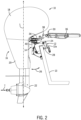
- FIGS 1 and 2 show an outboard motor 10 according to one example of the present disclosure.
- the outboard motor 10 comprises a transom clamp bracket 12 configured to be supported on a transom 13 of a marine vessel ( Figure 2 ) and a swivel bracket 14 configured to be supported by the transom clamp bracket 12.
- a propulsion unit 16 is configured to be supported by the swivel bracket 14, the propulsion unit 16 comprising a head unit 18, a midsection 20 below the head unit 18, and a lower unit 22 below the midsection 20.
- a propeller may be provided on the aft end of the lower unit 22, which propeller is powered to propel the marine vessel through water.
- outboard propulsion unit 16 may vary, and in other examples, the propulsion unit 16 may be a jet drive that utilizes an impeller instead of a propeller, or a forward-facing drive having a propeller on the fore side of the lower unit 22.
- the propulsion unit 16 may be powered by an internal combustion engine located in the head unit 18, or by an electric motor located in the head unit 18 or the lower unit 22.
- the head unit 18, midsection 20, and lower unit 22 are generally vertically aligned with one another when the outboard motor 10 is in a neutral tilt/trim position, as shown in Figures 1 and 2 .
- the propulsion unit 16 is tiltable and trimmable about a tilt tube 24, which defines a tilt/trim axis, as shown by arrow 26.
- the tilt tube 24 is connected between a pair of arms 12a, 12b of the transom clamp bracket 12, such as by the opposite ends of the tilt tube 24 extending through apertures in the arms 12a, 12b and being secured on the outer sides of the arms 12a, 12b with washers and nuts.
- the swivel bracket 14 is pivotably connected to the tilt tube 24 at the fore end of the swivel bracket 14, such as by the tilt tube 24 extending through apertures in the swivel bracket 14.
- the swivel bracket 14 is manually pivotable with respect to the transom clamp bracket 12 so as to tilt and/or trim the propulsion unit 16 with respect to the transom 13 of the marine vessel. Trimming of the propulsion unit 16 allows the propeller to be angled differently with respect to the transom 13, while tilting of the propulsion unit 16 allows the propulsion unit 16 to be moved to a transport position while the marine vessel to which it is connected is trailered.
- the "neutral" tilt/trim position is the one shown in Figure 2 , in which the propeller or other propulsor on the lower unit 22 would produce thrust (see arrow T) generally horizontally, and the longitudinal axis L running through the head unit 18, midsection 20, and lower unit 22 is generally vertically aligned.
- the transom clamp bracket 12 is attachable to the transom 13 of the marine vessel by adjustable clamps 28 that extend through each of the respective arms 12a, 12b of the transom clamp bracket 12 and are configured to rest on an inside surface of the transom 13.
- the outside surface of the transom 13 supports the opposite portions of the arms 12a, 12b of the transom clamp bracket 12, which are both configured with an upside-down U-shape to fit over the upper edge of the transom 13.
- a steering assembly 30 is connected to the propulsion unit 16, the steering assembly 30 comprising a steering tube 32 (see Figures 3 , 5 , and 11 ) configured to be supported by the swivel bracket 14 and a steering arm 34 supported by the steering tube 32.
- the steering arm 34 is connected to the propulsion unit 16, such as by being bolted thereto or such as by being integral with a support structure that holds or supports components within the head unit 18 and/or midsection 20.
- the steering assembly 30 also includes a tiller 36, which is coupled to the steering arm 34 by way of a bolted bracket 38.
- an operator can use the tiller 36 to steer the propulsion unit 16, control a speed of the propulsion unit 16, and interact with the propulsion unit 16 in other known ways to affect the magnitude and direction of thrust produced by the propulsion unit 16.
- the tiller 36 is pivotable about the bracket 38 connecting the tiller 36 to the steering arm 34 so as to place the tiller 36 in a folded, transport position.
- the tiller 36 is a conventional item, and the type and configuration of the tiller 36 can vary from what is shown. Suitable examples are disclosed in U.S. Patent Nos. 10,246,173 ; 9,789,945 ; 9,783,278 ; and 9,764,813 .
- the propulsion unit 16 is detachable from the transom clamp bracket 12.
- the propulsion unit 16 is detachable from the transom clamp bracket 12 without the use of tools, such as wrenches, screw drivers, or other tools other than the operator's hands, as will now be described.
- the outboard motor 10 is provided with an anti-theft device, which may require the use of a key or other type of unique key-like tool for removal of the propulsion unit 16 from the transom clamp bracket 12.
- Such anti-theft devices are usually aftermarket assemblies, and it is here noted that such a key is not considered to be a "tool" as discussed herein.
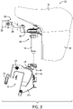
- FIG 3 illustrates the propulsion unit 16 detached from the transom clamp bracket 12.
- the steering assembly 30 (including steering tube 32 configured to be supported by the swivel bracket 14 and a steering arm 34 supported by the steering tube 32) is connected to the propulsion unit 16.
- the steering assembly 30 and the propulsion unit 16 are detachable together as a unit from the swivel bracket 14 and the transom clamp bracket 12. In other words, the steering assembly 30 and propulsion unit 16 remain connected together as they are separated from the swivel bracket 14.
- the steering tube 32, steering arm 34, and propulsion unit 16 are coupled in such a manner that the steering tube 32 can be lifted out of the swivel bracket 14, and with it the steering arm 34, tiller 36, and the propulsion unit 16.
- the swivel bracket 14 meanwhile remains coupled to the transom clamp bracket 12 way of the tilt tube 24.
- the transom clamp bracket 12 remains clamped with clamps 28 to the transom 13, while the propulsion unit 16 is be removed from the transom 13 and can be transported elsewhere.
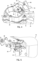
- Figures 4 shows a top starboard-side perspective view of a portion of the swivel bracket 14 without the steering tube 32 installed therein
- Figure 5 shows a port-side perspective view of the steering assembly 30 and propulsion unit 16 when the steering tube 32 is not installed in the swivel bracket 14.
- the swivel bracket 14 comprises a hollow tube 40 at the aft end thereof for receiving the steering tube 32 therein.
- the steering tube 32 is likewise tubular, and is sized and shaped to fit within the hollow tube 40 of the swivel bracket 14.
- the hollow tube 40 comprises a seat 42 therein.
- the seat 42 is located on the fore side of the hollow tube 40, but the seat 42 could be located elsewhere.
- the seat 42 is formed by a cup 43 that fits into the upper end of the hollow tube 40, but the seat 42 could instead be formed directly on the inner surface of the hollow tube 40.
- a housing 45 is supported on top of the cup 43, and the housing 45 and cup 43 have lugs 41 that allow them to be bolted to a flange on the upper end of the hollow tube 40.
- the housing 45 holds a pin 46 that extends through the swivel bracket 14, more specifically through the inner and outer walls of the housing 45.
- the pin 46 may be threaded along a portion of its length, as shown at 47, such that an operator can twist a handle 48 ( Figure 4 ), which is coupled to the pin 46 and provided outside the housing 45, so as to thread the pin 46 further into the swivel bracket 14 or further out of the swivel bracket 14.
- a nut 50 ( Figure 7 ) may be provided on the threaded portion 47, adjacent the inside wall of the housing 45, to secure the pin 46.
- the threaded portion 47 extends through the housing 45 so that the pin 46 cannot move on its own laterally within the housing 45. At least part of the end of the pin 46 that is within the hollow of the swivel bracket 14 is left unthreaded (as shown at 49), however, for reasons described below.
- the housing 45 and pin 46 are shown here as being on the port side of the outboard motor 10, in other examples, the housing 45 and pin 46 could be provided on the starboard side or the fore side of the swivel bracket 14.
- no housing is provided, and the pin 46 extends directly through the hollow tube 40 of the swivel bracket 14 and/or through the cup 43 therein.
- a housing for the pin 46 is formed integrally at the upper end of the hollow tube 40.
- the steering tube 32 comprises a fitting 52 provided on the outer surface of the steering tube 32.
- the outer diameter of the steering tube 32 where the fitting 52 is held can be reduced slightly in comparison to the outer diameter of the steering tube 32 above and below the fitting 52, so as to seat the fitting 52 at a particular location along the length of the steering tube 32. See Figure 11 .
- the fitting 52 on the steering tube 32 is configured to rest on the seat 42 within the hollow tube 40 of the swivel bracket 14 so as to support the steering tube 32 within the hollow tube 40 of the swivel bracket 14.
- the fitting 52 is sized and shaped to be seated directly against the seat 42.
- the fitting 52 has an upper, fore portion 54 that is configured to be seated in the upper, fore portion of the seat 42.
- the upper, fore portion 54 of the fitting 52 slopes downwardly to a lower, fore portion 56, which is cylindrical to match the cylindrical portion of the seat 42 in this location. Comparing Figures 9 and 7 , it can be seen that this taper or slope from the upper fore portion 54 to the lower fore portion 56 helps to guide the steering tube 32 into the hollow tube 40 of the swivel bracket 14 in the correct orientation.
- the cross-sectional shape of the fitting 52 is the same as the shape of the seat 42 and inside of the hollow tube 40.
- the steering tube 32 has a annular notch 60 provided in its outer surface, directly below where the steering tube 32 connects to the steering arm 34.
- the notch 60 extends around the outer surface of the steering tube 32 in the form of a band and has an upper surface 60a and lower surface 60b.
- the pin 46 that extends through the housing 45 of the swivel bracket 14 is configured to be received within the notch 60 in the steering tube 32.
- the diameter of the pin 46 at the non-threaded end 49 is configured to fit between the upper and lower surfaces 60a, 60b of the notch 60.
- the diameter of the pin 46 at the end 49 is shown as being just slightly smaller than the height of the notch 60 in the present example, the diameter of the pin 46 at the end 49 could be more significantly smaller than the height of the notch 60 in other examples.
- the pin 46 is configured to be moved between a locked position, shown in solid lines in Figure 11 , in which the pin 46 is received in the notch 60, and an unlocked position, shown in dashed lines in Figure 11 , in which the pin 46 is not received in the notch 60.
- a locked position shown in solid lines in Figure 11
- an unlocked position shown in dashed lines in Figure 11
- the pin 46 is not received in the notch 60.
- the handle 48 is twisted to unscrew the pin 46 and move it laterally outwardly away from the steering tube 32.
- the handle 48 is twisted to screw the pin 46 further laterally inwardly toward the steering tube 32.
- the steering tube 32 When the pin 46 is received in the notch 60, the steering tube 32 is prevented from being removed from the swivel bracket 14. Contact between the pin 46 and the lower surface 60b of the notch 60 prevents the steering tube 32 from being lifted out of the hollow tube 40 of the swivel bracket 14. With the pin 46 in the unlocked position, in which the pin 46 is not received in the notch 60, the steering tube 32 is able to be removed from the swivel bracket 14. The steering tube 32 is no longer prevented from being lifted upwardly by contact between the pin 46 and the lower surface 60b of the notch 60 after the pin 46 is withdrawn from the notch 60.
- the steering tube 32 comprises an outer tube 62 and an inner tube 64.
- the inner tube 64 rotates within the outer tube 62 when the operator steers the propulsion unit 16. This is because an upper end 64a of the inner tube 64 is connected to the steering arm 34 (at bolt 66), which is in turn connected to the bracket 38, which is in turn connected to the tiller 36.
- the inner tube 64 which extends upwardly above and out of the outer tube 62, which has the notch 60 formed in the outer surface thereof for receiving the pin 46.
- the inner end 49 of the pin 46 is not threaded, so that it can ride smoothly within the notch 60 in the inner tube 64 of the steering tube 32 as the inner tube 64 rotates within the swivel bracket 14.
- the outer tube 62 remains stationary as the tiller 36 is moved to steer the propulsion unit 16, because the fitting 52 seated around the outside of the outer tube 62 prevents rotation of the outer tube 62.
- An upper bearing 68 located concentrically with the fitting 52 and a lower bearing 70 at the lower end of the inner tube 64 facilitate smooth rotation of the inner tube 64 within the outer tube 62.
- a threaded end fitting 72 on the lower end of the outer tube 62 holds the lower bearing 70 in place.
- the operator turns the handle 48 of the pin 46 to move the pin 46 laterally outwardly away from the center of the hollow tube 40.
- the operator then lines up the fitting 52 on the steering tube 32 with the seat 42 within the hollow tube 40 of the swivel bracket 14, as shown in Figure 3 .
- the operator moves the propulsion unit 16 downwardly, inserting the steering tube 32 into the swivel bracket 14, until the fitting 52 is seated on the seat 42 within the hollow tube 40.
- the operator then twists the handle 48 on the pin 46 in the opposite direction, to move the pin 46 laterally inwardly until its non-threaded end 49 is located within the notch 60 in the steering tube 32.
- the operator turns the handle 48 of the pin 46 to move the pin 46 out of the notch 60, then lifts the propulsion unit 16 and steering assembly 30 connected thereto from the swivel bracket 14.
- a copilot 92 is held by the housing 45.
- the copilot 92 has a radially inwardly facing concave surface 94 that is configured to abut the outer circumferential surface 96 of the steering tube 32, more specifically of the inner tube 64 (see Figure 11 ).
- the copilot 92 is movable radially inwardly toward the steering tube 32 and radially outwardly away from the steering tube 32 by way of an actuator, here in the form of a bolt 97 connected to a handle 98 located outside the housing 45.
- actuators such as a ratcheting device, could be used.
- a spring 95 is provided about the bolt 97 and trapped between the inner surface of the housing 45 and the radially outward face of the copilot 92.
- the spring 95 biases the copilot 92 radially inwardly toward the steering tube 32.
- the bolt 97 is advanced inwardly toward the steering tube 32, thereby pressing the surface 94 of the copilot 92 against the outer surface 96 of the inner tube 64.
- a different amount of friction will be provided between the contacting surfaces 94 and 96.
- This friction can be great enough that the steering tube 32 is held in place despite attempted operator input to the tiller 36 or forces on the propulsion unit 16 as it moves through water, thus fixing the thrust direction of the propulsion unit 16.
- this friction can be adjusted to provide an operator-desired level of resistance to steering, while still allowing the tiller 36 to be moved to change the direction of thrust of the propulsion unit 16.
- the handle 98 is turned in the opposite direction.
- a plate 99 can be provided over the housing 45 to protect the copilot 92 and pin 46 from the elements. This plate 99 is removed in Figures 4 and 6 to better show the components within the housing 45.
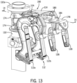
- FIGS 12-15 show portions of an outboard motor 110 according to another example of the present disclosure.
- the outboard motor 110 comprises a transom clamp bracket 112 configured to be supported on a transom of a marine vessel and a swivel bracket 114 configured to be supported by the transom clamp bracket 112.
- a propulsion unit 116 is configured to be supported by the swivel bracket 114, the propulsion unit 116 comprising a head unit, a midsection below the head unit, and a lower unit below the midsection.
- the propulsion unit 116 is shown generally in phantom, it being understood that the head unit, midsection, and lower unit are similar to those shown in Figure 1 .
- the head unit, midsection, and lower unit are generally vertically aligned with one another when the outboard motor 110 is in a neutral tilt/trim position (i.e., with the longitudinal axis of the propulsion unit 116 aligned generally vertically and the propulsor producing generally horizontal thrust).
- the propulsion unit 116 is detachable from the transom clamp bracket 112.
- the swivel bracket 114 is connected to the propulsion unit 116, such as being bolted thereto by bolts (not shown) extending through lugs 174 in the aft end of the swivel bracket 114 and into the propulsion unit 116, such as into a midsection housing thereof.
- the aft end of the swivel bracket 114 is curved such that the cylindrical steering tube 132 can be located therein.
- the flange at the upper end 132a of the steering tube 132 can be bolted to a steering arm (not shown), which is in turn coupled to a tiller (not shown).
- the swivel bracket 114 and propulsion unit 116 are detachable together as a unit from the transom clamp bracket 112. In other words, the swivel bracket 114 and propulsion unit 116 can remain connected together while they are both removed from the transom clamp bracket 112, which remains connected to the transom by way of the clamps 128.
- a tilt tube 124 is connected between a pair of arms 112a, 112b of the transom clamp bracket 112.
- the swivel bracket 114 can pivot about a pivot axis defined along the tilt tube 124, to manually tilt and trim the propulsion unit 116 with respect to the transom.
- the swivel bracket 114 comprises a notch 176 ( Figures 14B , 15 ) configured to receive and be supported by the tilt tube 124.
- a tab bracket 178 is provided on the swivel bracket 114.
- the tab bracket 178 is configured to be moved between a locked position ( Figure 14A ) in which the tilt tube 124 is trapped within the notch 176 by the tab bracket 178, and an unlocked position ( Figure 14B ) in which the tilt tube 124 is not trapped within the notch 176 by the tab bracket 178, and the swivel bracket 114 is able to be removed from the tilt tube 124.
- Figure 14B shows the swivel bracket 114 partially removed from the tilt tube 124 (or not yet fully installed on the tilt tube 124), with the tilt tube 124 not yet quite contacting the hollow of the notch 176, in order to show the notch 176 better.
- the tab bracket 178 is moved to the unlocked position of Figure 14B , i.e., pulled forward toward the transom.
- a pin 180 may be inserted into a hole 182 in the tab bracket 178 to maintain the tab bracket 178 in the unlocked position.
- no hole 182 is provided (see Figure 14A ), and the pin 180 simply rests on top of the tab bracket 178 when the tab bracket 178 is in the unlocked position.
- the operator positions the propulsion unit 116 and swivel bracket 114 so that the notch 176 in the underside of the swivel bracket 114 is aligned with the tilt tube 124, as shown in Figure 15 .
- the propulsion unit 116 and swivel bracket 114 are then lowered onto the transom clamp bracket 112, until the tilt tube 124 is fully inserted in the notch 176 ( Figure 14A ).
- the operator then pushes the tab bracket 178 aft (in the direction of arrow 186) until the aft end of the tab bracket 178 is located in a receiving space 188 in the lower surface of the swivel bracket 114.
- the pin 180 can then be inserted into a hole 184 to lock the tab bracket 178 in the locked position.
- the outboard motors 10, 110 comprise a transom clamp bracket 12, 112 configured to be supported on a transom 13 of a marine vessel and a propulsion unit 16, 116 configured to be supported by the transom clamp bracket 12, 112.
- the propulsion unit 16, 116 comprises a head unit 18, a midsection 20 below the head unit 18, and a lower unit 22 below the midsection 20, wherein the head unit 18, midsection 20, and lower unit 22 are generally vertically aligned with one another when the outboard motor 10, 110 is in a neutral tilt/trim position.
- the outboard motor 10, 110 has a support bracket assembly 90, 190 ( Figures 3 , 14A, B ) by way of which the propulsion unit 116 is suspended from the transom clamp bracket 12, 112, wherein the support bracket assembly 90, 190 and propulsion unit 16, 116 are detachable together as a unit from the transom clamp bracket 12, 112.
- the support bracket assembly 190 comprises a swivel bracket 114 supported by the transom clamp bracket 112, the swivel bracket 114 supporting the propulsion unit 116.
- the swivel bracket 114 is pivotable with respect to the transom clamp bracket 112 so as to tilt and/or trim the propulsion unit 116 with respect to the transom 13 of the marine vessel.
- the swivel bracket 114 is connected to the propulsion unit 116, and the swivel bracket 114 and propulsion unit 116 are detachable together as a unit from the transom clamp bracket 112.
- a tilt tube 124 is connected between a pair of arms 112a, 112b of the transom clamp bracket 112, wherein the swivel bracket 114 comprises a notch 176 configured to receive and be supported by the tilt tube 124.
- the support bracket assembly 190 further optionally comprises a tab bracket 178 on the swivel bracket 114, the tab bracket 178 configured to be moved between a locked position in which the tilt tube 124 is trapped within the notch 176 by the tab bracket 178, and an unlocked position in which the tilt tube 124 is not trapped within the notch 176 by the tab bracket 178 and the swivel bracket 114 is able to be removed from the tilt tube 124.
- a swivel bracket 14 is supported by the transom clamp bracket 12, and the support bracket assembly 90 comprises a steering tube 32 configured to be supported by the swivel bracket 14 and a steering arm 34 supported by the steering tube 32, wherein the steering arm 34 supports the propulsion unit 16.
- the steering arm 34 is connected to the propulsion unit 16, and the steering arm 34, steering tube 32, and propulsion unit 16 are detachable together as a unit from the swivel bracket 14 and the transom clamp bracket 12.
- a pin 46 extends through the swivel bracket 14 and is configured to be received within a notch 60 in the steering tube 32, the pin 46 being configured to be moved between a locked position in which the pin 46 is received in the notch 60 and the steering tube 32 is prevented from being removed from the swivel bracket 14, and an unlocked position in which the pin 46 is not received in the notch 60 and the steering tube 32 is able to be removed from the swivel bracket 14.
- the swivel bracket 14 comprises a hollow tube 40 for receiving the steering tube 32 therein.
- the hollow tube 40 comprises a seat 42 therein.
- the steering tube 32 comprises a fitting 52 configured to rest on the seat 42 so as to support the steering tube 32 within the hollow tube 40 of the swivel bracket 14.
- the support bracket assembly 90, 190 and propulsion unit 16, 116 are detachable together as a unit from the transom clamp bracket 12, 112 without the use of tools.
- the pin 46 can be screwed into and out of the swivel bracket 14 by hand via the handle 48.
- the tab bracket 178 can be pulled and pushed within the swivel bracket 114 by hand, and the pin 180 is also placeable by hand.
- the key or other type of unique key-like tool for removal of the propulsion unit 16, 116 from the transom clamp bracket 12, 112 is not considered to be a "tool" as referred to herein as not being required for such removal of the propulsion unit 16, 116.
- the propulsion units 16, 116 are steered remotely by input to a steering wheel, joystick, automatic steering algorithm, foot pedal, or other known steering device, which may be physically and/or electronically connected to the steering arm 34, 134 as appropriate.
- the transom clamp brackets 12, 112 are equipped with hydraulic, electric, or pneumatic tilt/trim systems, which may pivot the swivel bracket 14, 114 about the tilt tube 24, 124 so as to tilt and trim the propulsion unit 16, 116 with respect to the transom 13.
- the present inventors have solved the problem of needing to unclamp the clamps (e.g., 28, 128) that hold the transom clamp bracket to the transom every time an operator wants to remove the outboard motor for storage or transport.
- additional fasteners including screws, washers, and nuts, are recommended to add mounting security to the installation of the transom clamp bracket on the transom, but operators who want a portable outboard motor do not use these additional fasteners.
- Having a propulsion unit that can be removed from the transom clamp bracket allows an operator to safely and securely install the transom clamp bracket on the transom, while still providing the operator with the convenience of a transportable outboard motor.
Landscapes
- Chemical & Material Sciences (AREA)
- Engineering & Computer Science (AREA)
- Combustion & Propulsion (AREA)
- Mechanical Engineering (AREA)
- Ocean & Marine Engineering (AREA)
- Mutual Connection Of Rods And Tubes (AREA)
- Steering Controls (AREA)
Applications Claiming Priority (1)
| Application Number | Priority Date | Filing Date | Title |
|---|---|---|---|
| US17/487,116 US12377947B2 (en) | 2021-09-28 | 2021-09-28 | Outboard motor that is removable from transom clamp bracket |
Publications (1)
| Publication Number | Publication Date |
|---|---|
| EP4155191A1 true EP4155191A1 (de) | 2023-03-29 |
Family
ID=83283486
Family Applications (1)
| Application Number | Title | Priority Date | Filing Date |
|---|---|---|---|
| EP22195041.3A Pending EP4155191A1 (de) | 2021-09-28 | 2022-09-12 | Aussenbordmotor, der von einer riegelklammer abnehmbar ist |
Country Status (3)
| Country | Link |
|---|---|
| US (2) | US12377947B2 (de) |
| EP (1) | EP4155191A1 (de) |
| CN (1) | CN115871907A (de) |
Cited By (8)
| Publication number | Priority date | Publication date | Assignee | Title |
|---|---|---|---|---|
| US12162579B1 (en) | 2021-10-25 | 2024-12-10 | Brunswick Corporation | Integrated copilot and locking mechanism for marine drives |
| US12214851B1 (en) * | 2022-06-29 | 2025-02-04 | Brunswick Corporation | Copilot devices and apparatuses for supporting marine drives having a copilot device |
| EP4433357A4 (de) * | 2021-12-17 | 2025-03-05 | Brunswick Corporation | Transportable aussenbordmotoren |
| US12304605B2 (en) | 2022-08-09 | 2025-05-20 | Brunswick Corporation | Transom bracket assemblies for supporting a marine drive on a vessel |
| US12377947B2 (en) | 2021-09-28 | 2025-08-05 | Brunswick Corporation | Outboard motor that is removable from transom clamp bracket |
| US12403994B2 (en) | 2022-02-15 | 2025-09-02 | Brunswick Corporation | Tillers for marine drives having tilt mechanism |
| US12479552B1 (en) | 2022-10-05 | 2025-11-25 | Brunswick Corporation | Copilot devices and locking mechanisms for marine drives |
| US12570384B2 (en) | 2021-12-17 | 2026-03-10 | Brunswick Corporation | Transportable outboard motors |
Families Citing this family (10)
| Publication number | Priority date | Publication date | Assignee | Title |
|---|---|---|---|---|
| USD917565S1 (en) | 2017-07-13 | 2021-04-27 | Brunswick Corporation | Tiller for outboard motor |
| USD1043754S1 (en) | 2019-12-18 | 2024-09-24 | Brunswick Corporation | Outboard motor tiller |
| JP7350038B2 (ja) * | 2021-11-11 | 2023-09-25 | ヤマハ発動機株式会社 | 船外機の懸架構造、船外機 |
| US12391351B2 (en) | 2022-02-15 | 2025-08-19 | Brunswick Corporation | Tillers for marine drives having yaw adjustment device |
| US12545387B2 (en) | 2022-02-15 | 2026-02-10 | Brunswick Corporation | Tillers for marine drives having grip restraining device |
| US12528571B1 (en) | 2022-10-06 | 2026-01-20 | Brunswick Corporation | Tillers for marine drives having ambidextrous functionality |
| US12539953B1 (en) | 2022-10-18 | 2026-02-03 | Brunswick Corporation | Configurable shift and throttle mechanism for tiller of marine drive |
| EP4369561A3 (de) | 2022-11-11 | 2024-09-04 | Brunswick Corporation | Elektrische schiffsantriebssysteme und -verfahren |
| US12606288B1 (en) | 2022-11-11 | 2026-04-21 | Brunswick Corporation | Marine drive cowlings having access lid with hinge device |
| USD1098197S1 (en) | 2023-12-05 | 2025-10-14 | Brunswick Corporation | Tiller |
Citations (11)
| Publication number | Priority date | Publication date | Assignee | Title |
|---|---|---|---|---|
| US2808218A (en) * | 1955-07-29 | 1957-10-01 | John M Steller | Outboard motor mountings |
| JPS5654697U (de) * | 1979-10-05 | 1981-05-13 | ||
| JPS6479000A (en) * | 1987-05-06 | 1989-03-24 | Yanmar Diesel Engine Co | Outboard engine |
| US6053471A (en) * | 1997-07-29 | 2000-04-25 | Brown; Edward D. | Convertible, tilt-bracket assembly for mounting trolling motors |
| US6283806B1 (en) | 2000-05-22 | 2001-09-04 | Brunswick Corporation | Locking mechanism for an outboard motor |
| US6659817B1 (en) | 2002-10-15 | 2003-12-09 | Brunswick Corporation | Alignment system for an outboard motor |
| US9764813B1 (en) | 2016-08-15 | 2017-09-19 | Brunswick Corporation | Tillers, tiller systems and methods for controlling outboard motors with tillers |
| US9783278B1 (en) | 2016-08-15 | 2017-10-10 | Brunswick Corporation | Tiller having removable top cover |
| US9789945B1 (en) | 2016-08-15 | 2017-10-17 | Brunswick Corporation | Angularly adjustable tillers for outboard motors |
| US10246173B1 (en) | 2016-09-01 | 2019-04-02 | Brunswick Corporation | Tillers for outboard motors having neutral shift interlock mechanism |
| US11097824B1 (en) | 2020-02-06 | 2021-08-24 | Brunswick Corporation | Outboard motor having copilot device |
Family Cites Families (61)
| Publication number | Priority date | Publication date | Assignee | Title |
|---|---|---|---|---|
| US1451452A (en) * | 1920-11-22 | 1923-04-10 | Williams Hannah Totten | Tiller lock |
| US2549481A (en) | 1947-09-05 | 1951-04-17 | Elmer C Kiekhaefer | Reversible outboard motor |
| US2914020A (en) | 1958-06-04 | 1959-11-24 | Evert Van Raden | Outboard motor boat turn control means |
| US3961595A (en) | 1974-08-29 | 1976-06-08 | Brunswick Corporation | Steering apparatus for small outboard motors |
| US3922996A (en) | 1974-08-29 | 1975-12-02 | Brunswick Corp | Steering apparatus for outboard motors |
| US4018104A (en) | 1975-03-17 | 1977-04-19 | Caterpillar Tractor Co. | Frictionally held control linkage for engine throttle controls and the like |
| JPS58145596A (ja) | 1982-02-22 | 1983-08-30 | Sanshin Ind Co Ltd | 船外機の操舵装置 |
| JPS6133395A (ja) | 1984-07-25 | 1986-02-17 | Sanshin Ind Co Ltd | 船外機の操舵装置 |
| US4781634A (en) * | 1987-08-26 | 1988-11-01 | Brunswick Corporation | Water deflector for outboard motor |
| JP2905257B2 (ja) | 1990-04-25 | 1999-06-14 | 本田技研工業株式会社 | 船外機の弾性マウントを介した連結構造 |
| US5102357A (en) | 1991-01-08 | 1992-04-07 | Brunswick Corporation | Marine drive swivel bracket with tightened and retained clamp band |
| US5340342A (en) | 1993-06-02 | 1994-08-23 | Brunswick Corporation | Universal tiller handle with shift and throttle |
| JP3307754B2 (ja) | 1993-12-30 | 2002-07-24 | 三信工業株式会社 | 船外機におけるステアリング操作装置 |
| JP3957099B2 (ja) | 1997-10-01 | 2007-08-08 | ヤマハマリン株式会社 | 船外機のステアリングフリクション構造 |
| JP3976290B2 (ja) | 1998-08-05 | 2007-09-12 | ヤマハマリン株式会社 | 船外機の操舵角固定装置 |
| US6174211B1 (en) | 1998-05-29 | 2001-01-16 | Sanshin Kogyo Kabushiki Kaisha | Tiller lock for outboard motor |
| JP4297398B2 (ja) | 1999-11-19 | 2009-07-15 | ヤマハ発動機株式会社 | 船外機の格納構造 |
| US6402577B1 (en) | 2001-03-23 | 2002-06-11 | Brunswick Corporation | Integrated hydraulic steering system for a marine propulsion unit |
| US7048600B1 (en) | 2002-09-17 | 2006-05-23 | Kyle Broussard | Method and apparatus for air cooled outboard motor for small marine craft |
| CA2453466C (en) | 2002-12-25 | 2010-08-24 | Honda Motor Co., Ltd. | Outboard motor and tiller handle thereof |
| US7410397B2 (en) | 2004-05-10 | 2008-08-12 | Yamaha Marine Kabushiki Kaisha | Outboard motor with bracket assembly |
| US7090551B1 (en) | 2004-09-30 | 2006-08-15 | Brunswick Corporation | Outboard motor tiller handle with upward position locking device |
| US7303595B1 (en) | 2005-02-28 | 2007-12-04 | Brunswick Corporation | Impact absorbing isolator sleeve and assembly for mounting a trolling motor |
| CA2544069C (en) | 2005-04-26 | 2008-06-10 | Honda Motor Co., Ltd | Outboard motor |
| US7681513B1 (en) | 2005-05-27 | 2010-03-23 | Mark X Steering Systems Llc | Tiller operated marine steering system |
| US7244152B1 (en) | 2006-02-09 | 2007-07-17 | Brunswick Corporation | Support system for an outboard motor |
| US7311571B1 (en) | 2006-06-16 | 2007-12-25 | Brunswick Corporation | Hydraulic steering device for a marine propulsion system |
| US7758393B2 (en) | 2007-06-29 | 2010-07-20 | Brp Us Inc. | Engine mount system for a marine outboard engine |
| US20090170384A1 (en) | 2007-07-02 | 2009-07-02 | Brunswick Corporation | Support system for a marine propulsion device |
| US20110065340A1 (en) | 2007-10-29 | 2011-03-17 | Brunswick Corporation | Outboard motor steering structure |
| US7896304B1 (en) | 2008-08-19 | 2011-03-01 | Brunswick Corporation | Marine propulsion support mount system |
| US8069803B1 (en) | 2009-08-25 | 2011-12-06 | Peter James Crawford | Boat tiller restraining device |
| JP2012081900A (ja) | 2010-10-13 | 2012-04-26 | Yamaha Motor Co Ltd | 船舶推進装置 |
| US8795010B1 (en) | 2011-11-30 | 2014-08-05 | Brp Us Inc. | Drive unit mount for a marine outboard engine |
| JP2013244750A (ja) | 2012-05-23 | 2013-12-09 | Yamaha Motor Co Ltd | 船外機 |
| US8820701B1 (en) | 2012-11-28 | 2014-09-02 | Brunswick Corporation | Mounts, mounting arrangements, and methods of making mounting arrangements for supporting outboard motors with respect to marine vessels |
| US9643703B1 (en) | 2014-02-27 | 2017-05-09 | Brunswick Corporation | Vibration isolation mounting arrangement for outboard motor |
| US9376191B1 (en) | 2014-06-27 | 2016-06-28 | Brunswick Corporation | Outboard motor with lightweight midsection housing |
| US9623946B2 (en) | 2014-10-07 | 2017-04-18 | Stephen W. DeLise, SR. | Inboard/outboard with portable outdrive |
| US9481434B1 (en) | 2015-01-07 | 2016-11-01 | Brunswick Corporation | Midsection housing for an outboard motor with water-cooled mounts |
| US9463859B1 (en) | 2015-02-13 | 2016-10-11 | Brunswick Corporation | Adapter plate, heat shield, and method for thermally isolating a mount coupled to an adapter plate |
| US9616986B1 (en) | 2015-08-14 | 2017-04-11 | Arlon J. Gilk | Adjustable transom mount |
| US9701383B1 (en) | 2015-11-13 | 2017-07-11 | Brunswick Corporation | Outboard motor and marine propulsion support system |
| US9776699B1 (en) | 2015-12-10 | 2017-10-03 | Brunswick Corporation | Outboard motor with angled steering axis |
| JP2017213949A (ja) | 2016-05-30 | 2017-12-07 | スズキ株式会社 | 船外機 |
| US9963213B1 (en) | 2017-01-20 | 2018-05-08 | Brunswick Corporation | Mounting systems for outboard motors |
| US9969475B1 (en) | 2017-01-20 | 2018-05-15 | Brunswick Corporation | Mounting systems for outboard motors |
| CN206590092U (zh) | 2017-01-20 | 2017-10-27 | 水星海事技术(苏州)有限公司 | 船用舷外发动机转向手柄的抬升锁止机构 |
| US10124871B1 (en) | 2017-08-31 | 2018-11-13 | Brunswick Corporation | Shift systems that facilitate resilient mounting of an outboard motor with respect to a marine vessel |
| US10787236B1 (en) | 2018-02-01 | 2020-09-29 | Brunswick Corporation | Tiller tilt lock and automatic release system |
| US10464648B1 (en) * | 2018-03-15 | 2019-11-05 | Brunswick Corporation | Marine drives having sound blocking member |
| JP7081290B2 (ja) * | 2018-05-08 | 2022-06-07 | スズキ株式会社 | 電動式船外機 |
| US10696367B1 (en) | 2019-01-09 | 2020-06-30 | Brunswick Corporation | Tillers for outboard motors having reversible throttle grip direction |
| US11066140B1 (en) | 2019-12-13 | 2021-07-20 | Brunswick Corporation | Outboard motors having resilient mounting apparatuses |
| US11208190B1 (en) | 2020-06-23 | 2021-12-28 | Brunswick Corporation | Stern drives having breakaway lower gearcase |
| SI26066A (sl) | 2020-08-28 | 2022-03-31 | Remigo, Proizvodnja In Trgovina, D.O.O. | Integriran električni izvenkrmni motor |
| US12377947B2 (en) | 2021-09-28 | 2025-08-05 | Brunswick Corporation | Outboard motor that is removable from transom clamp bracket |
| US12214852B2 (en) | 2021-12-17 | 2025-02-04 | Brunswick Corporation | Outboard motors having side and rear laydown capability |
| US12275511B2 (en) | 2022-02-14 | 2025-04-15 | Brunswick Corporation | Marine drive having vented lower unit |
| US11866137B1 (en) | 2022-07-15 | 2024-01-09 | Brunswick Corporation | Marine drives having noise and vibration isolating joint |
| US12304605B2 (en) | 2022-08-09 | 2025-05-20 | Brunswick Corporation | Transom bracket assemblies for supporting a marine drive on a vessel |
-
2021
- 2021-09-28 US US17/487,116 patent/US12377947B2/en active Active
-
2022
- 2022-09-12 EP EP22195041.3A patent/EP4155191A1/de active Pending
- 2022-09-15 CN CN202211121547.8A patent/CN115871907A/zh active Pending
-
2025
- 2025-06-18 US US19/241,723 patent/US20250313322A1/en active Pending
Patent Citations (11)
| Publication number | Priority date | Publication date | Assignee | Title |
|---|---|---|---|---|
| US2808218A (en) * | 1955-07-29 | 1957-10-01 | John M Steller | Outboard motor mountings |
| JPS5654697U (de) * | 1979-10-05 | 1981-05-13 | ||
| JPS6479000A (en) * | 1987-05-06 | 1989-03-24 | Yanmar Diesel Engine Co | Outboard engine |
| US6053471A (en) * | 1997-07-29 | 2000-04-25 | Brown; Edward D. | Convertible, tilt-bracket assembly for mounting trolling motors |
| US6283806B1 (en) | 2000-05-22 | 2001-09-04 | Brunswick Corporation | Locking mechanism for an outboard motor |
| US6659817B1 (en) | 2002-10-15 | 2003-12-09 | Brunswick Corporation | Alignment system for an outboard motor |
| US9764813B1 (en) | 2016-08-15 | 2017-09-19 | Brunswick Corporation | Tillers, tiller systems and methods for controlling outboard motors with tillers |
| US9783278B1 (en) | 2016-08-15 | 2017-10-10 | Brunswick Corporation | Tiller having removable top cover |
| US9789945B1 (en) | 2016-08-15 | 2017-10-17 | Brunswick Corporation | Angularly adjustable tillers for outboard motors |
| US10246173B1 (en) | 2016-09-01 | 2019-04-02 | Brunswick Corporation | Tillers for outboard motors having neutral shift interlock mechanism |
| US11097824B1 (en) | 2020-02-06 | 2021-08-24 | Brunswick Corporation | Outboard motor having copilot device |
Cited By (9)
| Publication number | Priority date | Publication date | Assignee | Title |
|---|---|---|---|---|
| US12377947B2 (en) | 2021-09-28 | 2025-08-05 | Brunswick Corporation | Outboard motor that is removable from transom clamp bracket |
| US12162579B1 (en) | 2021-10-25 | 2024-12-10 | Brunswick Corporation | Integrated copilot and locking mechanism for marine drives |
| EP4433357A4 (de) * | 2021-12-17 | 2025-03-05 | Brunswick Corporation | Transportable aussenbordmotoren |
| US12545385B2 (en) | 2021-12-17 | 2026-02-10 | Brunswick Corporation | Transportable outboard motors |
| US12570384B2 (en) | 2021-12-17 | 2026-03-10 | Brunswick Corporation | Transportable outboard motors |
| US12403994B2 (en) | 2022-02-15 | 2025-09-02 | Brunswick Corporation | Tillers for marine drives having tilt mechanism |
| US12214851B1 (en) * | 2022-06-29 | 2025-02-04 | Brunswick Corporation | Copilot devices and apparatuses for supporting marine drives having a copilot device |
| US12304605B2 (en) | 2022-08-09 | 2025-05-20 | Brunswick Corporation | Transom bracket assemblies for supporting a marine drive on a vessel |
| US12479552B1 (en) | 2022-10-05 | 2025-11-25 | Brunswick Corporation | Copilot devices and locking mechanisms for marine drives |
Also Published As
| Publication number | Publication date |
|---|---|
| US20230102741A1 (en) | 2023-03-30 |
| US20250313322A1 (en) | 2025-10-09 |
| CN115871907A (zh) | 2023-03-31 |
| US12377947B2 (en) | 2025-08-05 |
Similar Documents
| Publication | Publication Date | Title |
|---|---|---|
| EP4155191A1 (de) | Aussenbordmotor, der von einer riegelklammer abnehmbar ist | |
| US11097824B1 (en) | Outboard motor having copilot device | |
| US11066140B1 (en) | Outboard motors having resilient mounting apparatuses | |
| US9764813B1 (en) | Tillers, tiller systems and methods for controlling outboard motors with tillers | |
| US9789945B1 (en) | Angularly adjustable tillers for outboard motors | |
| EP0200375B1 (de) | Steuervorrichtungsträger für Motorboot | |
| US11046411B2 (en) | Tiller assembly for a marine outboard engine | |
| US12304605B2 (en) | Transom bracket assemblies for supporting a marine drive on a vessel | |
| CA2960098C (en) | Steering mechanism for a boat having a planing hull | |
| EP3569488B1 (de) | Aussenbordmotor | |
| US6913497B1 (en) | Tandem connection system for two or more marine propulsion devices | |
| JP4836652B2 (ja) | 船外機 | |
| JP2001073313A (ja) | コンクリート仕上げトロエル及びその操縦方法 | |
| US12570384B2 (en) | Transportable outboard motors | |
| US6283806B1 (en) | Locking mechanism for an outboard motor | |
| US20110065340A1 (en) | Outboard motor steering structure | |
| EP0847367B1 (de) | Montageanordnung für den steuerzylinder eines aussenbordmotors | |
| JPH07196092A (ja) | 船外機におけるステアリング操作装置 | |
| US20220185402A1 (en) | Personal mobility device | |
| US4731035A (en) | Steering mechanism for outboard motors | |
| US6776671B2 (en) | Trolling motor steering linkage system | |
| US5358434A (en) | Mounting apparatus for trolling motor | |
| JPH0438294A (ja) | 船舶推進機の操縦装置 | |
| US7056169B1 (en) | Connection device for a marine propulsion system | |
| US20110113920A1 (en) | Steering Wheel Control Arm |
Legal Events
| Date | Code | Title | Description |
|---|---|---|---|
| PUAI | Public reference made under article 153(3) epc to a published international application that has entered the european phase |
Free format text: ORIGINAL CODE: 0009012 |
|
| STAA | Information on the status of an ep patent application or granted ep patent |
Free format text: STATUS: THE APPLICATION HAS BEEN PUBLISHED |
|
| AK | Designated contracting states |
Kind code of ref document: A1 Designated state(s): AL AT BE BG CH CY CZ DE DK EE ES FI FR GB GR HR HU IE IS IT LI LT LU LV MC MK MT NL NO PL PT RO RS SE SI SK SM TR |
|
| P01 | Opt-out of the competence of the unified patent court (upc) registered |
Effective date: 20230330 |
|
| STAA | Information on the status of an ep patent application or granted ep patent |
Free format text: STATUS: REQUEST FOR EXAMINATION WAS MADE |
|
| 17P | Request for examination filed |
Effective date: 20230918 |
|
| RBV | Designated contracting states (corrected) |
Designated state(s): AL AT BE BG CH CY CZ DE DK EE ES FI FR GB GR HR HU IE IS IT LI LT LU LV MC MK MT NL NO PL PT RO RS SE SI SK SM TR |
|
| STAA | Information on the status of an ep patent application or granted ep patent |
Free format text: STATUS: EXAMINATION IS IN PROGRESS |
|
| 17Q | First examination report despatched |
Effective date: 20240318 |
|
| GRAP | Despatch of communication of intention to grant a patent |
Free format text: ORIGINAL CODE: EPIDOSNIGR1 |
|
| STAA | Information on the status of an ep patent application or granted ep patent |
Free format text: STATUS: GRANT OF PATENT IS INTENDED |
|
| RIC1 | Information provided on ipc code assigned before grant |
Ipc: B63H 20/02 20060101AFI20260325BHEP Ipc: B63H 20/08 20060101ALN20260325BHEP Ipc: B63H 20/06 20060101ALN20260325BHEP Ipc: B63H 20/12 20060101ALN20260325BHEP |