EP4155192B1 - Profil pour un bord de fuite d'un profil aérodynamique et son procédé de réparation - Google Patents
Profil pour un bord de fuite d'un profil aérodynamique et son procédé de réparation Download PDFInfo
- Publication number
- EP4155192B1 EP4155192B1 EP21382870.0A EP21382870A EP4155192B1 EP 4155192 B1 EP4155192 B1 EP 4155192B1 EP 21382870 A EP21382870 A EP 21382870A EP 4155192 B1 EP4155192 B1 EP 4155192B1
- Authority
- EP
- European Patent Office
- Prior art keywords
- profile
- trailing edge
- airfoil
- sections
- recesses
- Prior art date
- Legal status (The legal status is an assumption and is not a legal conclusion. Google has not performed a legal analysis and makes no representation as to the accuracy of the status listed.)
- Active
Links
Images




Classifications
-
- B—PERFORMING OPERATIONS; TRANSPORTING
- B64—AIRCRAFT; AVIATION; COSMONAUTICS
- B64F—GROUND OR AIRCRAFT-CARRIER-DECK INSTALLATIONS SPECIALLY ADAPTED FOR USE IN CONNECTION WITH AIRCRAFT; DESIGNING, MANUFACTURING, ASSEMBLING, CLEANING, MAINTAINING OR REPAIRING AIRCRAFT, NOT OTHERWISE PROVIDED FOR; HANDLING, TRANSPORTING, TESTING OR INSPECTING AIRCRAFT COMPONENTS, NOT OTHERWISE PROVIDED FOR
- B64F5/00—Designing, manufacturing, assembling, cleaning, maintaining or repairing aircraft, not otherwise provided for; Handling, transporting, testing or inspecting aircraft components, not otherwise provided for
- B64F5/40—Maintaining or repairing aircraft
-
- F—MECHANICAL ENGINEERING; LIGHTING; HEATING; WEAPONS; BLASTING
- F01—MACHINES OR ENGINES IN GENERAL; ENGINE PLANTS IN GENERAL; STEAM ENGINES
- F01D—NON-POSITIVE DISPLACEMENT MACHINES OR ENGINES, e.g. STEAM TURBINES
- F01D5/00—Blades; Blade-carrying members; Heating, heat-insulating, cooling or antivibration means on the blades or the members
- F01D5/12—Blades
- F01D5/28—Selecting particular materials; Particular measures relating thereto; Measures against erosion or corrosion
- F01D5/282—Selecting composite materials, e.g. blades with reinforcing filaments
-
- B—PERFORMING OPERATIONS; TRANSPORTING
- B64—AIRCRAFT; AVIATION; COSMONAUTICS
- B64C—AEROPLANES; HELICOPTERS
- B64C3/00—Wings
- B64C3/28—Leading or trailing edges attached to primary structures, e.g. forming fixed slots
-
- B—PERFORMING OPERATIONS; TRANSPORTING
- B64—AIRCRAFT; AVIATION; COSMONAUTICS
- B64C—AEROPLANES; HELICOPTERS
- B64C9/00—Adjustable control surfaces or members, e.g. rudders
- B64C9/14—Adjustable control surfaces or members, e.g. rudders forming slots
- B64C9/16—Adjustable control surfaces or members, e.g. rudders forming slots at the rear of the wing
-
- F—MECHANICAL ENGINEERING; LIGHTING; HEATING; WEAPONS; BLASTING
- F05—INDEXING SCHEMES RELATING TO ENGINES OR PUMPS IN VARIOUS SUBCLASSES OF CLASSES F01-F04
- F05D—INDEXING SCHEME FOR ASPECTS RELATING TO NON-POSITIVE-DISPLACEMENT MACHINES OR ENGINES, GAS-TURBINES OR JET-PROPULSION PLANTS
- F05D2230/00—Manufacture
- F05D2230/80—Repairing, retrofitting or upgrading methods
-
- F—MECHANICAL ENGINEERING; LIGHTING; HEATING; WEAPONS; BLASTING
- F05—INDEXING SCHEMES RELATING TO ENGINES OR PUMPS IN VARIOUS SUBCLASSES OF CLASSES F01-F04
- F05D—INDEXING SCHEME FOR ASPECTS RELATING TO NON-POSITIVE-DISPLACEMENT MACHINES OR ENGINES, GAS-TURBINES OR JET-PROPULSION PLANTS
- F05D2240/00—Components
- F05D2240/20—Rotors
- F05D2240/30—Characteristics of rotor blades, i.e. of any element transforming dynamic fluid energy to or from rotational energy and being attached to a rotor
- F05D2240/304—Characteristics of rotor blades, i.e. of any element transforming dynamic fluid energy to or from rotational energy and being attached to a rotor related to the trailing edge of a rotor blade
Definitions
- the present invention belongs to the field of aeronautical structures such as an aircraft airfoil, and in particular to the profiles that are coupled to a trailing edge of an airfoil.
- the present invention provides a method to repair the trailing edge of an aircraft airfoil.
- the aircraft airfoils such as horizontal tail plane (HTP), vertical tail plane (VTP), flaps, wings or ailerons, are normally manufactured in two pieces, a lower piece and an upper piece which are both joined with a U or V shaped profile at the trailing edge of the airfoil by rivets or sometimes by glue. That is, to avoid leave a space between these two pieces at the trailing edge of the airfoil, currently it is closed the trailing edge with a folded sheet of aluminum or steel of a small thickness and with a U or V shape. This folded sheet is drilled to the two pieces of the airfoil at the trailing edge and later is riveted with through rivets that join such two pieces. By means of this joint, the two pieces being protected against leaks and lightning.
- HTP horizontal tail plane
- VTP vertical tail plane
- flaps flaps
- wings or ailerons are normally manufactured in two pieces, a lower piece and an upper piece which are both joined with a U or V shaped profile at the trailing edge of the airf
- this profile that attach the two pieces is a metallic profile parallel to a flange of the trailing edge that joins two skins with rivets.
- a filler i.e., epoxy
- the provision of a filler increases weight and the cost on hand labor hours.
- Another drawback of using the filler is that the filler takes approximately 24 hours to cure, and then it is needed to sand and polish the filler in order to ensure that the profile follows the aerodynamic contour of the airfoil. This means the lead time of the piece is very long and many hours of operators, which affects the total cost of the completed airfoil.
- due to the great changes in the atmosphere to which the filler is subjected usually subject this filler a stress that leads to the appearance of cracks that gives a bad appearance for the airfoil.
- the present invention proposes a new profile configuration that solves the drawbacks indicated above, and also proposes an improved method to repair these new profiles in an aircraft airfoil.
- Document EP3683139A1 describes a flight control surface for an aircraft and method for manufacturing said flight control surface.
- the present invention provides a solution for the aforementioned problems, by a profile for a trailing edge according to claim 1, a trailing edge according to claim 7, a method to repair a trailing edge according to claim 9, and an aircraft according to claim 11.
- the present invention provides a profile for a trailing edge of an airfoil, the trailing edge comprising two flanges, the profile is U or V shaped and is made of composite material.
- An aircraft airfoil usually comprises a leading edge and a trailing edge opposed to the leading edge.
- the leading edge from an airfoil is the front part of the airfoil, which is the portion that meets the external airflow first when it is airflowing outside the airfoil in operating mode, whereas the trailing edge is the back part of the airfoil that is located axially downstream from the leading edge according to an airflow direction.
- the "airflow direction" will be understood as the airflow direction that corresponds to the direction of the external airflow surrounding the airfoil when it is in operating mode, that is, a direction from the leading edge to the trailing edge of the airfoil.
- the airfoil is formed by two pieces joined at the leading edge and ending at the trailing edge in the form of two flanges.
- the profile has a U or V shaped configuration which allows to hug or cover the trailing edge, and in particular the flanges, so that this profile is configured to be coupled to these flanges. That is, the profile is designed to be mounted as a clamp on the trailing edge flanges to be coupled to them.
- a profile made of composite material is now proposed for the present invention.
- the profile comprises:
- the profile will be understood as a one-piece structural component formed by two sections that meet at one end of the profile, the first profile end, thus giving rise to the U or V shaped configuration.
- the profile further comprises for each section a second profile end opposed to the first profile end, this second profile end being configured to be complementary to a surface of the trailing edge. That is, the first profile end is common for both sections while each section comprises a second profile end.
- These two sections defines an inner space between them and the first profile end. In particular, the inner space is further delimited by the second profile ends of the sections.
- the profile further comprises a plurality of recesses located at both sections along a transversal direction that is transverse to the airflow direction. These recesses projects towards the inside of the profile, that is, towards the inner space.
- the recesses of one section are complementary with the recesses of the other sections, this means that each recess of a section is coincident with another recess of the other section according to a direction perpendicular to the airflow direction and the transversal direction.
- the profile is configured to follow the theoretical aerodynamic contour of the airfoil so that when the profile is mounted on the trailing edge the two sections partially cover the trailing edge and the flanges are housed inside the inner space.
- this profile follows the theoretical aerodynamic contour of the aircraft airfoil means that when the profile is coupled to the airfoil in an operative mode, there is a superficial continuity between the surfaces of each profile section and the surfaces of the aircraft airfoil. When this superficial continuity is achieved, it is understood that the theoretical aerodynamic contour of the airfoil is extended to the included profile.
- the theoretical aerodynamic contour will be understood as the theoretical surface that surrounds an aerodynamic profile or airfoil.
- the flanges of the trailing edge are covered by the profiled and housed in the inner space of this profile, and the second ends of the profile are complementary to the surface of the trailing edge in order that there is surface transition between the profile and the trailing edge but rather a superficial continuity is achieved between them.
- Each recess of the plurality of recesses defines at least two joining points through which the two flange of the trailing edge and the two sections are configured to be joined each other. In an operative mode, both trailing edge flanges and the two sections of the profile are joined together at these joining points by means of rivets.
- joining points are to be understood as a reference in the external surface of the profile and not as an additional structural component in the profile.
- these joining points could be marked on the surface of the profile sections so that during the assembly of the profile to the airfoil, these points are taken as references to provide the rivets for the joining.
- the present profile provides an improved profile that reduces parasitic drag and weight when is assembled to a trailing edge of an airfoil.
- the parasitic drag and weight reduction in turn leads to a cost and time of production reduction and operations and repairs reductions.
- the present profile reduces the joining points between the profile and the trailing edge of an airfoil only to the joining points arranges at the recesses of the profile.
- the fact that these joining points are located at the recesses hides the rivet heads from the aerodynamic contour of the profile and consequently of the entire airfoil.
- the recesses also provide stability to the profile which leads in reducing the use of filler or sealant between the profile and the wedged of the airfoil to which the profile is to be coupled.
- the present profile provides a weight reduction by itself and when it is coupled to an airfoil, the flutter effect is therefore also reduced.
- Flutter is an aerodynamic vibration induced from a control surface that can lead to total structural failure in the airfoil.
- weight is eliminated from the rear area (trailing edge) of the airfoils, which entails a remove of floating masses in the trailing edge of the airfoils, and therefore this improves the behavior against flutter effect, thus reducing the provision of this phenomenon comparing to the prior art solution.
- composite material for the manufacturing of the profile provides a thermal loads reduction compared with the metallic profile of the prior art. This is due to the material of the profile is the same material (composite material) as that of the airfoil and its trailing edge, and therefore the dilatation of both components profile and airfoil will be the same since both would behave the same way.
- the present profile reduce or eliminate the use of filler or sealant and this leads in a cost savings and in reduction of application time.
- the provision of filler or sealant requires approximately 24 hours to cure and then needs to be sand and polished in order to ensure the aerodynamic contour. Therefore, the reductions of filler or sealant is an advantages over time, costs and operators work. Additionally, this also provides a weight decrease for the airfoil and thus a fuel and environmental cost reduction.
- each section comprises a support section configured to rest on the trailing edge.
- This support section corresponds to the second profile end that is opposed to the first profile end. That is, the support section of the profile will be understood as the portion of the profile that rests on the trailing edge of the airfoil when the profile is in an operative mode coupled to the airfoil.
- the support section comprises at least a projection that projects towards the inner space and is configured to couple and sealant the profile to the trailing edge.
- the projection protrudes beyond the thickness of the profile and is intended to rest on the trailing edge of the airfoil.
- the profile with such projections at the support section are provided for a better sealant and attachment between the profile and the airfoil.
- the support section comprises a plurality of projections.
- the projection has a triangular and / or circular shape according to a cross sectional view of the profile.
- This cross sectional view of the profile corresponds to a cross sectional plane of the profile that comprises que airflow direction and is transversal to the first profile end.
- the projections are located at a second profile end opposed to the first profile end and / or before the second profile end of the sections. That is, the projection can be arranged close to the edge of the profile at its second profile end or slightly away from this profile edge. By having the projections at the second profile end or very close to it, these projections help sealing the profile to the trailing edge or act as a stop on the trailing edge.
- the profile is machined at its end or close to it to provide space for the projection and thus guarantee a better coupling and closure of the profile to the trailing edge.
- the recesses are boxed swaging recesses. This particular configuration of recesses provides to the profile more stability thus avoiding the excessive use of filler or sealant between the profile and the airfoil and the drawbacks that this present.
- the recesses comprises a rest surface that is parallel to the surface of the trailing edge flanges.
- the profile is made of reused or scrap composite materials.
- the reused or scrap material can be the same material that is used for the manufacture of the same components as other parts or other aircraft programs. This supposes a reuse of a material very expensive as carbon fiber can be and a great impact on the environment. In this sense, a great advantage is provided since it is reused a material with very good mechanical properties that was going to be wastes, which entails a very low cost of material for the production of the present profile.
- the distance between the joining points of recesses are predefined distances according to the airfoil on which the profile is configured to be coupled, so that each distance defines at least a predefined pattern of a profile portion.
- the present profile is configured to advantageously fit in any part of the airfoil to be attached, the dimensions of the profile change according to each airfoil. For example, the pitch of joining points or the distance between joining points are determined for each airfoil to which the profile is coupled. Therefore, a distance between two joining points of the recesses represents a predefined patter that corresponds to a portion of the profile. That is, it is understood that the profile is conform by several portions defined by a parameter that corresponds to the distance between two joining points.
- the present invention provides a trailing edge of an airfoil, the trailing edge comprising:
- the trailing edge comprises another joining points where the flanges are attached together by means of second rivets.
- the length of the first rivets is greater than the length of the second rivets.
- the trailing edge further comprising a filler or sealant where the second profile ends touch the trailing edge.
- the filler or sealant is provided along the completed second profile end between this end and the trailing edge. The provision of the filler or sealant guarantees good sealing and water tightness between the profile and the trailing edge.
- the invention provides filler or sealant between the profile and the recesses also for improve the sealing and the water tightness between them.
- the present invention provides a method to repair a trailing edge according to the second inventive aspect, the method comprising the following steps:
- a portion of the profile including the damage is cut from the rest of the profile.
- This profile portion is already predefined for the manufacture of the profile. That is, depending on where the damage is found in the profile, this region of the profile will corresponds to a profile portion that follows a predefined pattern. Since the dimension of the profile portion to be cut is predetermined, another profile portion without damage is provided that will replace the damaged profile portion.
- This predefined pattern refers to the dimension of a profile portion according to a predefined distance between joining points of recesses. Therefore, the damaged portion of the profile is replaced by another one without damage and with the same size as the damaged portions.
- the present method allows a faster and easier profile repairs compared to the prior art solution since fewer rivets are needed to be removed and riveted from the profile. Therefore, this method is faster and more efficient to the previous and provides a reduction of the number of operator hours and time on ground of the aircraft.
- each spare portion may comprise several subportions that also follows a predefined pattern.
- the spare portion can be cut before be installed in order to be adjusted to the dimension of the damaged portion to be replaced.
- the present method reduce repair time by more than 80% thanks to the new profile configuration that facilitates the reparation of the same.
- the step (b) is performed cutting the profile from a recess to another recess including at least one joining point and the first rivet of each recess.
- the profile portion to be cut extends from one recess to another including at least one first rivet for each recess.
- the method only needs to remove at least two first rivets corresponding to the portion to be cut.
- the step (e) is performed by riveting the first rivets on the joining points of the profile. Furthermore, the method comprises applying a sealant or filler on the edge of the new profile portion.
- the invention provides an aircraft comprising an airfoil with a trailing edge according to the second inventive aspect.
- the airfoil is a horizontal tail plane, a vertical tail plane, flap, wing, elevator, rudder or aileron.
- Figure 1 shows a schematically cross sectional view of a profile (10) attached to the trailing edge (11) of an airfoil (12).
- the trailing edge (11) comprises two flanges (13, 14) one arranged on top of the other according to the airflow direction.
- the profile (10) has a U-shaped configuration and comprises two sections (1, 2) that are joined or connected at the first profile end (1.1). This profile (10) defines an inner space (3) between the sections (1, 2) in which the flanges (13, 14) of the trailing edge are housed.
- the profile (10) shown in this figure comprises for each section (1, 2) a recess (4) that projects towards the inner space (3), that is towards the inside of the profile (10) with the aim to rest on the flange (13, 14) surfaces.
- both recesses (4) are complementary between sections (1, 2), and this means that both are aligned.
- Each recess (4) comprises two joining points (5) at the surface of the recess (4). Through this joining points the profile (10) surface and the two flanges (13, 14) are attached together by means of first rivets (not shown in this figure). Since this first rivets cross from one section (1) of the profile to another section (2), crossing the flanges (13, 14) of the trailing edge in turn, it is understood that both recesses (4) need to be coincident or complementary between them.
- the profile (10) further comprises a second profile ends (1.2) in each section (1, 2), being these second profile ends (1.2) the area of the profile (10) that contacts with the trailing edge (11).
- the trailing edge (11) also comprises a variable thickness portion (6) with a ramp-shaped surface that comprises two sections, a first surface section (6.1) having a greater inclination than the second surface section (6.2).
- the second profile end (1.2) rest on the first surface section (6.1) of the trailing edge (11), ,in particular, it is a support structure (8) of the profile (10) which rest on the trailing edge (11).
- the rest of the profile (10) on the trailing edge (11) provides a surface continuity between the second surface section (6.2) of the trailing edge (11) and the surface of the profile (10) at each section (1, 2), and therefore the profile (10) partially covers the trailing edge (11).
- the second profile ends (1.2) comprise a configuration that is complementary to the surface of the trailing edge (11), thus achieving the profile (10) to follow the theoretical aerodynamic contour of the airfoil (12).
- each recess (4) support on a surface of the flanges (13, 14) that is parallel to the airflow direction, and therefore, each recess (4) has a base surface intended to be parallel to the airflow direction.
- the profile (10) is made of composite materials, and preferably, reused or scrap composite materials.
- FIGs 2, 3-3A and 4-4A show a schematically profile (10) as shown in figure 1 with different embodiments for the configuration at its support sections (8).
- the support section (8) has the same thickness as the rest of the profile (10) or the respective section (1, 2). That is, in this case the support section (8) is a continuation of the profile sections (1, 2).
- figures 3-3A and 4-4A shows a profile (10) where the support section (8) comprises at least one projection (8.1) projecting towards inside the profile (10), that is, towards the inner space (3).
- This projections (8.1) coupled and optionally sealant the profile (10) to the trailing edge (11).
- the projections (8.1) is in contact with the surface of the trailing edge (11) when the profile (10) is in an operative mode coupled to the trailing edge (11).
- the projection has a triangular and/or circular shape.
- figures 3, 3A and 4 show a projection (8.1) each with a different triangular shape.
- figure 4A shows a projection (8.1) with a circular shape.
- the projection can be understood as an independent protrusion for each section or that can be repeated along the profile for each section, or as a continuous protruding element along the profile for each section.
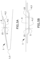
- Figures 5A-5B show two different cross sectional views of one section (1) of a profile (10) as the previous ones with a boxed swaging recess (4).
- the recess (4) comprises a base surface (4.1) and a ramp surface (4.2), both surfaces (4.1, 4.2) of the recess (4) are a continuation of the surface of a section (1).
- the base surface (4.1) is intended to rest on a flange (13, 14) surface of a trailing edge (11), therefore the base surface (4.1) is parallel to the flange (13, 14) surface.
- This recess (4) shows a hole (15) located on a joining point (5) of the recess (4) for allowing to rivet the profile (10) to the trailing edge (11) by means of first rivets.
- Figure 5B shows a recess (4) comprising two holes (15) on the base surface (4.1), each hole (15) arranged at a joining point (5) of the profile (10). Additionally, as it can be observed on figure 5B , this recess (4) comprises two ramp lateral surfaces (4.3).
- Figure 6 shows a profile (10) portion according to a plan view where it can be observed three recess (4), one of these recesses (4) comprises two joining points, another recess (4) comprises three joining points (5), and the last one comprises four joining points (5) but only two are represented on the figure.
- These joining points (5) represent the location where the profile (10) is attached to the trailing edge (11) by riveting first rivets.
- the flanges (13, 14) of the trailing edge (11) are attached together by means of second rivets in joining points distributed along the surface of the flanges (13, 14) so that being located between the recesses (4) when the profile (10) is assembled to the trailing edge (11).
- this figure 6 shows these joining points between flanges where the second rivets would be riveted just for the purpose of showing where they would be arranged, clarifying that these are not on the profile (10).
- Figure 7 shows a perspective view of a profile (10) made of composite material and comprises a first (1) and second (2) section joined at a first profile end (1.1) which configure a U-shaped profile (10).
- This profile (10) shows two recesses (4) for each section (1, 2) being coincident between sections (1, 2) according to a vertical direction through which the first rivets attach the profile (10) to the trailing edge (11).
- Figure 9 shows an aircraft (16) comprising airfoils or lifting surfaces (12) such as wings, horizontal tail plane or vertical tail plane. These airfoils or lifting surfaces (12) comprising a profile (10) as already described above attached to the trailing edge (11) of such airfoils (12).
- the present invention further discloses a method to repair a profile (10) once it is assembled to a trailing edge (11) as described above. This method comprises the following steps:
- a profile portion (9) including the damage (7) is cut according to step (b).
- This profile portion (9) corresponds to a predefined pattern. Specifically, this predefined pattern is provided by the distance between joining points (5) of the recesses (4). That is, the dimension of the profile portion (9) to be cut has already predefined according to the airfoil (12) which the profile (10) is to be coupled.
- the profile portion (9) with the damage (7) is cut between two adjacent recesses (4) including a joining point (5) for each recess (4).
- the cutting lines (18) are also shown in this figure 8 .
- the method comprises the step (c) of removing such damaged profile portion (9) already cut and replacing this damaged profile portion (9) by a new profile portion (9) with the same predefined patterns as the damaged portion. That is, in step (d) another profile portion (9) with the same dimensions as the profile portion (9) already removed is provided (as it shown on figure 8A ) to be attached according to the last step (e) of the method.
- the replacement profile portion (9) is attached to the trailing edge (11) to an airfoil (12) with a repair profile (10) according to step (e).
- This attachment only requires riveting a first rivet in each joining point (5) of each recess (4) of the replacement profile portion (9) to the trailing edge (11) of an airfoil (12).
- a filler or sealant can be also applied between the second profile ends (1.2) of the profile portion (9) and the trailing edge (11).
Landscapes
- Engineering & Computer Science (AREA)
- Aviation & Aerospace Engineering (AREA)
- Chemical & Material Sciences (AREA)
- Materials Engineering (AREA)
- Mechanical Engineering (AREA)
- Composite Materials (AREA)
- General Engineering & Computer Science (AREA)
- Manufacturing & Machinery (AREA)
- Transportation (AREA)
- Structures Of Non-Positive Displacement Pumps (AREA)
Claims (12)
- Profil (10) pour un bord de fuite (11) d'un profil aérodynamique (12), le bord de fuite (11) comprenant deux brides (13, 14), dans lequelle profil (10) est en forme de U ou de V et constitué de matériau composite,le profil (10) comprenant :- deux sections (1, 2) jointes au niveau d'une première extrémité de profil (1.1) et définissant un espace interne (3), et- une pluralité d'évidements (4) agencés le long des deux sections (1, 2) vers l'espace interne (3) et étant complémentaires l'un de l'autre entre les deux sections (1, 2) ;dans lequelle profil (10) est configuré pour suivre le contour aérodynamique théorique du profil aérodynamique (12) de sorte que lorsque le profil (10) est monté sur le bord de fuite (11), les deux sections (1, 2) recouvrent partiellement le bord de fuite (11) et les brides (13, 14) soient logées à l'intérieur de l'espace interne (3) ;chaque évidement de la pluralité d'évidements (4) définit au moins deux points de jonction (5) par le biais desquels les deux brides (13, 14) du bord de fuite (11) et les deux sections (1, 2) sont configurées pour être jointes les unes aux autres ; etchaque section (1, 2) comprend une section de support (8) configurée pour reposer sur le bord de fuite (11) ;dans lequella section de support (8) comprend au moins une saillie (8.1) qui fait saillie vers l'espace interne (3) et est configurée pour coupler et facultativement sceller le profil (10) au bord de fuite (11) ; etla saillie (8.1) a une forme triangulaire et/ou circulaire selon une vue en coupe transversale du profil (10).
- Profil (10) selon la revendication précédente, dans lequel la saillie (8.1) est située au niveau d'une deuxième extrémité de profil (1.2) opposée à la première extrémité de profil (1.1) et/ou avant la deuxième extrémité de profil (1.2) des sections (1, 2).
- Profil (10) selon l'une quelconque des revendications précédentes, dans lequel les évidements (4) sont des évidements par emboutissage en boîte.
- Profil (10) selon l'une quelconque des revendications précédentes, comprenant en outre pour chaque section (1, 2) une deuxième extrémité de profil (1.2) opposée à la première extrémité de profil (1.1), la deuxième extrémité de profil (1.2) étant configurée pour être complémentaire d'une surface du bord de fuite (11).
- Profil (10) selon l'une quelconque des revendications précédentes, dans lequel le profil (10) est constitué de matériaux composites réutilisés ou mis au rebut.
- Profil (10) selon l'une quelconque des revendications précédentes, dans lequel les distances entre les points de jonction (5) d'évidements (4) sont des distances prédéfinies selon le profil aérodynamique (12) sur lequel le profil (10) est configuré pour être couplé, de sorte que chaque distance définisse au moins un motif prédéfini d'une partie de profil (9).
- Bord de fuite (11) d'un profil aérodynamique (12), le bord de fuite (11) comprenant :- deux brides (13, 14) agencées au niveau d'une extrémité du bord de fuite (11),- un profil (10) selon l'une quelconque des revendications précédentes,- une pluralité de premiers rivets agencés au niveau des points de jonction (5) du profil (10) pour attacher les deux brides (13, 14) aux sections (1, 2) du profil (10), et- une pluralité de deuxièmes rivets agencés entre les évidements (4) du profil (10) pour attacher des brides (13, 14) du bord de fuite (11) entre elles.
- Bord de fuite (11) selon la revendication 7, comprenant en outre une charge ou un matériau scellement où les deuxièmes extrémités de profil (1.2) touchent le bord de fuite (11).
- Procédé pour réparer un bord de fuite (11) selon l'une quelconque des revendications 7 à 8, le procédé comprenant les étapes suivantes :(a) identification d'au moins un endommagement (7) sur le profil (10) du bord de fuite (11),(b) découpe du profil (10) selon un motif prédéfini d'une partie de profil (9) où l'endommagement (7) est fourni,(c) retrait de la partie de profil (9) découpée avec l'endommagement (7),(d) fourniture d'une autre partie de profil (9) qui suit le même motif prédéfini que la partie de profil (9) qui a été retirée, et(e) attache de la nouvelle partie de profil (9) au bord de fuite (11) pour obtenir un bord de fuite (11) avec profil (10) réparé.
- Procédé selon la revendication 9, dans lequel l'étape (b) est réalisée en découpant le profil (10) d'un évidement (4) à un autre évidement (4) incluant au moins un point de jonction (5) et le premier rivet de chaque évidement (4).
- Aéronef (16) comprenant un profil aérodynamique (12) avec un bord de fuite (11) selon l'une quelconque des revendications 7 à 8.
- Aéronef (16) selon la revendication 11, dans lequel le profil aérodynamique (12) est un stabilisateur horizontal, un stabilisateur vertical, un volet, une aile, une gouverne de profondeur, une gouverne de direction ou un aileron.
Priority Applications (2)
| Application Number | Priority Date | Filing Date | Title |
|---|---|---|---|
| EP21382870.0A EP4155192B1 (fr) | 2021-09-28 | 2021-09-28 | Profil pour un bord de fuite d'un profil aérodynamique et son procédé de réparation |
| US17/954,127 US11952914B2 (en) | 2021-09-28 | 2022-09-27 | Profile for a trailing edge of an airfoil and method to repair thereof |
Applications Claiming Priority (1)
| Application Number | Priority Date | Filing Date | Title |
|---|---|---|---|
| EP21382870.0A EP4155192B1 (fr) | 2021-09-28 | 2021-09-28 | Profil pour un bord de fuite d'un profil aérodynamique et son procédé de réparation |
Publications (2)
| Publication Number | Publication Date |
|---|---|
| EP4155192A1 EP4155192A1 (fr) | 2023-03-29 |
| EP4155192B1 true EP4155192B1 (fr) | 2025-02-12 |
Family
ID=78413916
Family Applications (1)
| Application Number | Title | Priority Date | Filing Date |
|---|---|---|---|
| EP21382870.0A Active EP4155192B1 (fr) | 2021-09-28 | 2021-09-28 | Profil pour un bord de fuite d'un profil aérodynamique et son procédé de réparation |
Country Status (2)
| Country | Link |
|---|---|
| US (1) | US11952914B2 (fr) |
| EP (1) | EP4155192B1 (fr) |
Family Cites Families (6)
| Publication number | Priority date | Publication date | Assignee | Title |
|---|---|---|---|---|
| US2613893A (en) * | 1948-04-01 | 1952-10-14 | Curtiss Wright Corp | Airfoil construction |
| ES2367935B1 (es) * | 2008-12-18 | 2012-09-18 | Airbus Operations, S.L. | Borde de salida de superficie estabilizadora de aeronave. |
| ES2421410B1 (es) * | 2012-02-29 | 2014-10-28 | Airbus Operations, S.L. | Borde de salida de una superficie aerodinamica de una aeronave |
| WO2016060734A1 (fr) * | 2014-10-17 | 2016-04-21 | COLBURN II, Philmore H. | Pièce de réparation pour pale de rotor |
| EP3683139B1 (fr) * | 2019-01-18 | 2021-07-28 | Airbus Operations, S.L.U. | Surface de commande de vol pour aéronef et procédé de fabrication dudit de surface de commande de vol |
| US11312507B2 (en) * | 2019-09-03 | 2022-04-26 | The Boeing Company | Repair assembly to repair an area on a member of a vehicle |
-
2021
- 2021-09-28 EP EP21382870.0A patent/EP4155192B1/fr active Active
-
2022
- 2022-09-27 US US17/954,127 patent/US11952914B2/en active Active
Also Published As
| Publication number | Publication date |
|---|---|
| EP4155192A1 (fr) | 2023-03-29 |
| US20230102672A1 (en) | 2023-03-30 |
| US11952914B2 (en) | 2024-04-09 |
Similar Documents
| Publication | Publication Date | Title |
|---|---|---|
| CN102300770B (zh) | 飞行器稳定装置表面后缘 | |
| CA2652661C (fr) | Lisse destinee a une aile d'avion et procede de formation de celle-ci | |
| EP3683139B1 (fr) | Surface de commande de vol pour aéronef et procédé de fabrication dudit de surface de commande de vol | |
| EP2804811B1 (fr) | Bande à logements de dispositifs de fixation | |
| EP2046639B1 (fr) | Lisse d'aile d'avion et son procédé de formation | |
| US8371537B2 (en) | Aircraft structure with hinge rib assembly | |
| US8286911B2 (en) | Fitting for pivotally connecting aerodynamic control element to aircraft structure | |
| US3429023A (en) | Manufacture of aerodynamic structures | |
| US10435133B2 (en) | Low stress stiffener runout in Pi bonded structure | |
| EP4155192B1 (fr) | Profil pour un bord de fuite d'un profil aérodynamique et son procédé de réparation | |
| US20220119093A1 (en) | Flow body for an aircraft having a solid trailing-edge component | |
| US7216429B2 (en) | Methods for replacement of a slotted tail rotor blade pitch horn | |
| US20080042011A1 (en) | Cover panel for an aircraft wing and a method of forming thereof | |
| US7677496B2 (en) | Stringer for an aircraft wing and a method of reinforcing thereof | |
| US10906629B2 (en) | Leading edge skin structure | |
| EP3031712B1 (fr) | Empennage horizontal et procédé de fabrication dudit empennage | |
| CN106737275B (zh) | 737cl型飞机大翼后梁上缘条修理切割定位工具及方法 | |
| US10392132B2 (en) | Curved aircraft substructure repair systems and methods | |
| US12006064B2 (en) | Manufacturing method of a control surface of an aircraft and aircraft control surface | |
| CN106828879A (zh) | 一种复合材料连接接头 | |
| US12466539B2 (en) | Leading edge device for an aerodynamic component and method for manufacturing a leading-edge device for an aerodynamic component | |
| EP4371872A1 (fr) | Dispositif de bord d'attaque pour un composant aérodynamique et procédé de fabrication d'un dispositif de bord d'attaque pour un composant aérodynamique | |
| CN211442730U (zh) | 一种机翼梁间肋 | |
| CN119749839A (zh) | 一种支撑肋、舵面及方法 |
Legal Events
| Date | Code | Title | Description |
|---|---|---|---|
| PUAI | Public reference made under article 153(3) epc to a published international application that has entered the european phase |
Free format text: ORIGINAL CODE: 0009012 |
|
| STAA | Information on the status of an ep patent application or granted ep patent |
Free format text: STATUS: THE APPLICATION HAS BEEN PUBLISHED |
|
| AK | Designated contracting states |
Kind code of ref document: A1 Designated state(s): AL AT BE BG CH CY CZ DE DK EE ES FI FR GB GR HR HU IE IS IT LI LT LU LV MC MK MT NL NO PL PT RO RS SE SI SK SM TR |
|
| STAA | Information on the status of an ep patent application or granted ep patent |
Free format text: STATUS: REQUEST FOR EXAMINATION WAS MADE |
|
| 17P | Request for examination filed |
Effective date: 20230928 |
|
| RBV | Designated contracting states (corrected) |
Designated state(s): AL AT BE BG CH CY CZ DE DK EE ES FI FR GB GR HR HU IE IS IT LI LT LU LV MC MK MT NL NO PL PT RO RS SE SI SK SM TR |
|
| GRAP | Despatch of communication of intention to grant a patent |
Free format text: ORIGINAL CODE: EPIDOSNIGR1 |
|
| STAA | Information on the status of an ep patent application or granted ep patent |
Free format text: STATUS: GRANT OF PATENT IS INTENDED |
|
| INTG | Intention to grant announced |
Effective date: 20240904 |
|
| GRAS | Grant fee paid |
Free format text: ORIGINAL CODE: EPIDOSNIGR3 |
|
| GRAA | (expected) grant |
Free format text: ORIGINAL CODE: 0009210 |
|
| STAA | Information on the status of an ep patent application or granted ep patent |
Free format text: STATUS: THE PATENT HAS BEEN GRANTED |
|
| AK | Designated contracting states |
Kind code of ref document: B1 Designated state(s): AL AT BE BG CH CY CZ DE DK EE ES FI FR GB GR HR HU IE IS IT LI LT LU LV MC MK MT NL NO PL PT RO RS SE SI SK SM TR |
|
| REG | Reference to a national code |
Ref country code: GB Ref legal event code: FG4D |
|
| REG | Reference to a national code |
Ref country code: CH Ref legal event code: EP |
|
| REG | Reference to a national code |
Ref country code: DE Ref legal event code: R096 Ref document number: 602021025970 Country of ref document: DE |
|
| REG | Reference to a national code |
Ref country code: IE Ref legal event code: FG4D |
|
| REG | Reference to a national code |
Ref country code: NL Ref legal event code: MP Effective date: 20250212 |
|
| PG25 | Lapsed in a contracting state [announced via postgrant information from national office to epo] |
Ref country code: RS Free format text: LAPSE BECAUSE OF FAILURE TO SUBMIT A TRANSLATION OF THE DESCRIPTION OR TO PAY THE FEE WITHIN THE PRESCRIBED TIME-LIMIT Effective date: 20250512 |
|
| PG25 | Lapsed in a contracting state [announced via postgrant information from national office to epo] |
Ref country code: FI Free format text: LAPSE BECAUSE OF FAILURE TO SUBMIT A TRANSLATION OF THE DESCRIPTION OR TO PAY THE FEE WITHIN THE PRESCRIBED TIME-LIMIT Effective date: 20250212 |
|
| PG25 | Lapsed in a contracting state [announced via postgrant information from national office to epo] |
Ref country code: PL Free format text: LAPSE BECAUSE OF FAILURE TO SUBMIT A TRANSLATION OF THE DESCRIPTION OR TO PAY THE FEE WITHIN THE PRESCRIBED TIME-LIMIT Effective date: 20250212 |
|
| PG25 | Lapsed in a contracting state [announced via postgrant information from national office to epo] |
Ref country code: ES Free format text: LAPSE BECAUSE OF FAILURE TO SUBMIT A TRANSLATION OF THE DESCRIPTION OR TO PAY THE FEE WITHIN THE PRESCRIBED TIME-LIMIT Effective date: 20250212 |
|
| REG | Reference to a national code |
Ref country code: LT Ref legal event code: MG9D |
|
| PG25 | Lapsed in a contracting state [announced via postgrant information from national office to epo] |
Ref country code: NO Free format text: LAPSE BECAUSE OF FAILURE TO SUBMIT A TRANSLATION OF THE DESCRIPTION OR TO PAY THE FEE WITHIN THE PRESCRIBED TIME-LIMIT Effective date: 20250512 Ref country code: IS Free format text: LAPSE BECAUSE OF FAILURE TO SUBMIT A TRANSLATION OF THE DESCRIPTION OR TO PAY THE FEE WITHIN THE PRESCRIBED TIME-LIMIT Effective date: 20250612 |
|
| PG25 | Lapsed in a contracting state [announced via postgrant information from national office to epo] |
Ref country code: NL Free format text: LAPSE BECAUSE OF FAILURE TO SUBMIT A TRANSLATION OF THE DESCRIPTION OR TO PAY THE FEE WITHIN THE PRESCRIBED TIME-LIMIT Effective date: 20250212 |
|
| PG25 | Lapsed in a contracting state [announced via postgrant information from national office to epo] |
Ref country code: HR Free format text: LAPSE BECAUSE OF FAILURE TO SUBMIT A TRANSLATION OF THE DESCRIPTION OR TO PAY THE FEE WITHIN THE PRESCRIBED TIME-LIMIT Effective date: 20250212 |
|
| PG25 | Lapsed in a contracting state [announced via postgrant information from national office to epo] |
Ref country code: LV Free format text: LAPSE BECAUSE OF FAILURE TO SUBMIT A TRANSLATION OF THE DESCRIPTION OR TO PAY THE FEE WITHIN THE PRESCRIBED TIME-LIMIT Effective date: 20250212 Ref country code: PT Free format text: LAPSE BECAUSE OF FAILURE TO SUBMIT A TRANSLATION OF THE DESCRIPTION OR TO PAY THE FEE WITHIN THE PRESCRIBED TIME-LIMIT Effective date: 20250612 |
|
| PG25 | Lapsed in a contracting state [announced via postgrant information from national office to epo] |
Ref country code: BG Free format text: LAPSE BECAUSE OF FAILURE TO SUBMIT A TRANSLATION OF THE DESCRIPTION OR TO PAY THE FEE WITHIN THE PRESCRIBED TIME-LIMIT Effective date: 20250212 Ref country code: GR Free format text: LAPSE BECAUSE OF FAILURE TO SUBMIT A TRANSLATION OF THE DESCRIPTION OR TO PAY THE FEE WITHIN THE PRESCRIBED TIME-LIMIT Effective date: 20250513 |
|
| REG | Reference to a national code |
Ref country code: AT Ref legal event code: MK05 Ref document number: 1765849 Country of ref document: AT Kind code of ref document: T Effective date: 20250212 |
|
| PG25 | Lapsed in a contracting state [announced via postgrant information from national office to epo] |
Ref country code: SE Free format text: LAPSE BECAUSE OF FAILURE TO SUBMIT A TRANSLATION OF THE DESCRIPTION OR TO PAY THE FEE WITHIN THE PRESCRIBED TIME-LIMIT Effective date: 20250212 |
|
| PG25 | Lapsed in a contracting state [announced via postgrant information from national office to epo] |
Ref country code: SM Free format text: LAPSE BECAUSE OF FAILURE TO SUBMIT A TRANSLATION OF THE DESCRIPTION OR TO PAY THE FEE WITHIN THE PRESCRIBED TIME-LIMIT Effective date: 20250212 |
|
| PG25 | Lapsed in a contracting state [announced via postgrant information from national office to epo] |
Ref country code: DK Free format text: LAPSE BECAUSE OF FAILURE TO SUBMIT A TRANSLATION OF THE DESCRIPTION OR TO PAY THE FEE WITHIN THE PRESCRIBED TIME-LIMIT Effective date: 20250212 |
|
| PGFP | Annual fee paid to national office [announced via postgrant information from national office to epo] |
Ref country code: DE Payment date: 20250919 Year of fee payment: 5 |
|
| PG25 | Lapsed in a contracting state [announced via postgrant information from national office to epo] |
Ref country code: IT Free format text: LAPSE BECAUSE OF FAILURE TO SUBMIT A TRANSLATION OF THE DESCRIPTION OR TO PAY THE FEE WITHIN THE PRESCRIBED TIME-LIMIT Effective date: 20250212 |
|
| PGFP | Annual fee paid to national office [announced via postgrant information from national office to epo] |
Ref country code: GB Payment date: 20250919 Year of fee payment: 5 |
|
| PG25 | Lapsed in a contracting state [announced via postgrant information from national office to epo] |
Ref country code: AT Free format text: LAPSE BECAUSE OF FAILURE TO SUBMIT A TRANSLATION OF THE DESCRIPTION OR TO PAY THE FEE WITHIN THE PRESCRIBED TIME-LIMIT Effective date: 20250212 |
|
| PGFP | Annual fee paid to national office [announced via postgrant information from national office to epo] |
Ref country code: FR Payment date: 20250922 Year of fee payment: 5 |
|
| PG25 | Lapsed in a contracting state [announced via postgrant information from national office to epo] |
Ref country code: EE Free format text: LAPSE BECAUSE OF FAILURE TO SUBMIT A TRANSLATION OF THE DESCRIPTION OR TO PAY THE FEE WITHIN THE PRESCRIBED TIME-LIMIT Effective date: 20250212 Ref country code: CZ Free format text: LAPSE BECAUSE OF FAILURE TO SUBMIT A TRANSLATION OF THE DESCRIPTION OR TO PAY THE FEE WITHIN THE PRESCRIBED TIME-LIMIT Effective date: 20250212 |
|
| PG25 | Lapsed in a contracting state [announced via postgrant information from national office to epo] |
Ref country code: RO Free format text: LAPSE BECAUSE OF FAILURE TO SUBMIT A TRANSLATION OF THE DESCRIPTION OR TO PAY THE FEE WITHIN THE PRESCRIBED TIME-LIMIT Effective date: 20250212 |
|
| PG25 | Lapsed in a contracting state [announced via postgrant information from national office to epo] |
Ref country code: SK Free format text: LAPSE BECAUSE OF FAILURE TO SUBMIT A TRANSLATION OF THE DESCRIPTION OR TO PAY THE FEE WITHIN THE PRESCRIBED TIME-LIMIT Effective date: 20250212 |
|
| REG | Reference to a national code |
Ref country code: DE Ref legal event code: R097 Ref document number: 602021025970 Country of ref document: DE |
|
| PLBE | No opposition filed within time limit |
Free format text: ORIGINAL CODE: 0009261 |
|
| STAA | Information on the status of an ep patent application or granted ep patent |
Free format text: STATUS: NO OPPOSITION FILED WITHIN TIME LIMIT |
|
| 26N | No opposition filed |
Effective date: 20251113 |