EP4155202B1 - Schwerkraft- und/oder pneumatischer rückhalte- und freigabemechanismus für eine externe, in der luft schwebende last - Google Patents
Schwerkraft- und/oder pneumatischer rückhalte- und freigabemechanismus für eine externe, in der luft schwebende last Download PDFInfo
- Publication number
- EP4155202B1 EP4155202B1 EP22188721.9A EP22188721A EP4155202B1 EP 4155202 B1 EP4155202 B1 EP 4155202B1 EP 22188721 A EP22188721 A EP 22188721A EP 4155202 B1 EP4155202 B1 EP 4155202B1
- Authority
- EP
- European Patent Office
- Prior art keywords
- load
- mechanism according
- supports
- release
- restrain
- Prior art date
- Legal status (The legal status is an assumption and is not a legal conclusion. Google has not performed a legal analysis and makes no representation as to the accuracy of the status listed.)
- Active
Links
Images


Classifications
-
- B—PERFORMING OPERATIONS; TRANSPORTING
- B64—AIRCRAFT; AVIATION; COSMONAUTICS
- B64D—EQUIPMENT FOR FITTING IN OR TO AIRCRAFT; FLIGHT SUITS; PARACHUTES; ARRANGEMENT OR MOUNTING OF POWER PLANTS OR PROPULSION TRANSMISSIONS IN AIRCRAFT
- B64D1/00—Dropping, ejecting, releasing or receiving articles, liquids, or the like, in flight
- B64D1/02—Dropping, ejecting, or releasing articles
- B64D1/04—Dropping, ejecting, or releasing articles the articles being explosive, e.g. bombs
- B64D1/06—Bomb releasing; Bomb doors
-
- B—PERFORMING OPERATIONS; TRANSPORTING
- B64—AIRCRAFT; AVIATION; COSMONAUTICS
- B64D—EQUIPMENT FOR FITTING IN OR TO AIRCRAFT; FLIGHT SUITS; PARACHUTES; ARRANGEMENT OR MOUNTING OF POWER PLANTS OR PROPULSION TRANSMISSIONS IN AIRCRAFT
- B64D1/00—Dropping, ejecting, releasing or receiving articles, liquids, or the like, in flight
- B64D1/02—Dropping, ejecting, or releasing articles
- B64D1/08—Dropping, ejecting, or releasing articles the articles being load-carrying devices
- B64D1/12—Releasing
-
- B—PERFORMING OPERATIONS; TRANSPORTING
- B64—AIRCRAFT; AVIATION; COSMONAUTICS
- B64D—EQUIPMENT FOR FITTING IN OR TO AIRCRAFT; FLIGHT SUITS; PARACHUTES; ARRANGEMENT OR MOUNTING OF POWER PLANTS OR PROPULSION TRANSMISSIONS IN AIRCRAFT
- B64D7/00—Arrangement of military equipment, e.g. armaments, armament accessories or military shielding, in aircraft; Adaptations of armament mountings for aircraft
- B64D7/08—Arrangement of rocket launchers
-
- B—PERFORMING OPERATIONS; TRANSPORTING
- B33—ADDITIVE MANUFACTURING TECHNOLOGY
- B33Y—ADDITIVE MANUFACTURING, i.e. MANUFACTURING OF THREE-DIMENSIONAL [3D] OBJECTS BY ADDITIVE DEPOSITION, ADDITIVE AGGLOMERATION OR ADDITIVE LAYERING, e.g. BY 3D PRINTING, STEREOLITHOGRAPHY OR SELECTIVE LASER SINTERING
- B33Y80/00—Products made by additive manufacturing
Definitions
- the present invention generally relates to restrain and release systems for airborne loads (BRU, Bomb Rack Unit) which are used in the aeronautical and aerospace industries for constraining an external load to the structure of the aircraft (carriage), releasing it and thus safely separating it upon the pilot's command (release or jettison). More particularly, the invention relates to ejection release mechanisms (ERU, Ejector Release Unit).
- BRU Airborne loads
- ERU Ejector Release Unit
- ERU Ejector Release Unit
- the stems may be operated through a high-pressure gas obtained by activating explosive cartridges (Pyro ERU), or through air stored under high pressure (Cold Gas ERU) .
- Gravity Release Unit the load is released but it is separated only through gravity.
- the systems for releasing the load by ejection are typical of high-performance aircraft, in which the safe separation is strongly affected by the velocity with which the load is released (end of stroke velocity); the systems for releasing the load by gravity are applied on helicopters or low performance aircraft, wherein the sole dropping by gravity is sufficient to guarantee the correct separation of the load.
- the European patent EP2750970 B1 discloses a system for releasing the load by ejection in which, in order to separate a load from an aircraft, there is provided for a pair of telescopic stems with several stages, which can be extended pneumatically.
- the high-pressure air is provided by a pneumatic system installed on board the aircraft comprising a pair of smaller gas cylinders and a larger cylinder connected to the telescopic stems by means of a complex rotary turntable valve system.
- Document US2021237886 discloses an aeronautical conveying and release device comprising a frame, an actuator releasing a device, a first and second hook holding the device, first and second locking toggles having a locking and unlocking position, first and second cams in contact with the first or second toggle in a first direction.
- the object of the present invention is to provide a mechanism for restraining and releasing an airborne load which combines the simplicity of embodiment on the aircraft characteristic of the gravity devices with the effectiveness of ejection of the load characteristic of devices provided with ejection means.
- the object of the invention is to provide a restrain and release mechanism provided with pneumatic ejection means that is compact and light, however without reducing the structural strength required to bear the loads generated in flight.
- this object is attained thanks to a mechanism for restraining and releasing an external airborne load of the type defined in the preamble of claim 1, whose primary characteristic lies in the fact that the load supports are made hollow so as to form the tank for the compressed air.
- the pneumatic system required to operate the telescopic stems is entirely embedded in the restrain and release mechanism according to the invention, making it ready and easy to install on the aircraft onto which it is designed to be installed.
- Such mechanism is therefore effectively capable of combining the simplicity of installation inherent of the solution with release of the load by gravity with the versatility of devices with the ejection of the load.
- each load support consists of a hollow monolithic metal body made by means of an additive manufacturing process.
- the structural characteristics of the monolithic metal body ensure that the arms have small overall dimensions and they are extremely light, while maintaining the strength appropriate to bear both the pressure of the compressed air therein and the external loads under all operating conditions of the aircraft. Furthermore, the additive manufacturing technique makes such arms manufacturable in a relatively simple, quick, reliable and cost-effective manner.
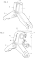
- each of the load supports consists of an inverted Y-shaped body, having an upper central section provided with an internal seat for housing the telescopic stem, and from which a pair of support arms branch out inferiorly.
- the body of the mechanism comprises a pneumatic connection which connects the hollow load supports together.
- each stem is held in the retracted position by the pressure exerted by the constrained load on an end plate of each stem.
- the invention also relates to a system for restraining an external load for use in the aeronautical and aerospace industries, comprising a restrain and release mechanism according to the invention, in which each load support consists of a swivelling pad arm.
- the systems designed to transport and release external loads for aircraft in flight have the task of ensuring the absence of relative motions between the loads and the support structure onto which they are suspended hence simultaneously ensuring the correct controlled separation of the load from the aircraft.
- the restrain and release mechanism according to the invention is of the conventional type. Therefore, only the essential components and those expressly referred to in the invention will be described herein.
- the release mechanism comprises a central body 1 with extended parallelepiped shape, from which there protrudes a pair of electric connections C which connect the on-board systems of the aircraft to a CPU for controlling the mechanism, not shown given that it is generally known.
- a releasable load locking device is indicated with 10; in this embodiment, such device comprises a hook 10 for each of the load supports 2,3.
- Each hook 10 is movable between a raised load restrain position, visible in figure 4 , and a lowered release position, visible in figure 5 .
- the mechanical system designed to operate the hooks 10, not shown, is based on a conventional articulated quadrilateral normally including a pair of solenoids operating in a parallel fashion by redundancy.
- the mechanism according to the invention comprises a pneumatic device for moving away the load during its release, including a pair of telescopic stems 11 operated by compressed air.
- Each stem 11 comprises two coaxially slidable shanks 12,13 in the respective cylinder 19 and subjected to the action of the pressurised air supplied to the thrust chamber 17 which acts on the shanks 12,13 moving the stem 11 from the retracted inoperative position within a respective of the aforementioned seats 19 of the central sections 4,5 of the bodies 15, visible in figure 4 , to a load thrust position, visible in figure 5 , in which the shanks 12,13 of the stems 11 protrude inferiorly with respect to the arms 6-7,8-9.
- the aforementioned load supports 2,3 are made hollow so as to form a tank for the compressed air.
- the arms 6-7,8-9 and an inner peripheral portion of each central section 4,5 of the supports 2,3 comprise airtight cavities 18 connected to each other so as to form the tank for storing the compressed air required for operating the pneumatic device for moving away the load.
- each load support 2,3 consists of an inverted Y-shaped hollow monolithic metal body 15, made by means of a per se known additive manufacturing process.
- each hollow monolithic metal body 15 is capable, in use, to store the pressurised air required to operate the stems 11 which move the load away, significantly reducing the overall dimensions of the mechanism according to the invention.
- Such advantage is further enhanced by the fact that besides the chambers 18 even the cylinders 19 of the telescopic stems 11 are integrated in the supports 2, 3 by means of the aforementioned additive manufacturing process.
- the mechanism according to the invention allows to drastically facilitate installation on the designated aircraft, while maintaining high effectiveness in moving away the load whenever there arises the need.
- each support 2,3 comprises a duct 16 which places the cavity 18 for storing the compressed air in communication with the internal thrust chamber 17 of the cylinder 19 of the respective thrust stem 11.
- the mechanism according to the invention comprises a pneumatic connection 23,24, partially embedded in the body 1, which connects the load supports 2,3 together, therefore ensuring a uniform pressure acting on the two telescopic stems 11: a condition required to have a thrust force which acts on the load in a balanced manner, allowing its release without pitch.
- an air inlet 21 so as to load/unload the compressed air
- a manometer 22 to display the pressure value in the mechanism.
- the mechanism according to the invention may provide for a safety device which, lying on the air inlet 21, prevents the manual opening of the system should pressurised air be present in the circuit.
- the thrust chambers 17 of the telescopic stems 11 When transporting the load, the thrust chambers 17 of the telescopic stems 11 are subjected to an initial pressure, given by the compressed air in the volume inside the supports 2,3. However, the shanks 11,12 are held in the retracted position by the pressure action exerted by the still constrained load on the end plate 25 of each stem 11.
- the movement for releasing the hooks 10 of the device for suspending the load allows to release the load from the supports 2,3 and, the action for extending the shanks 12,13 of the stems 11 free to move at this point, imparts a force for moving away the load by means of the plate 25.
- Such force is proportional to the pressure of the compressed air contained in the storage tank, formed by the cavities of the load supports 2,3, which are in turn pneumatically connected to the thrust chambers 18 of the stems 11.
- the action of the stems 11 of the mechanism according to the invention allows to move the load away from the aircraft with an acceleration greater than that of gravity, over the entire duration of their mechanical stroke.
- the load continues the separation step remaining subjected to the force of gravity alone.
- the pressure value used when loading the tanks determines the final load ejection velocity, proportional to its mass and inertia.
- this architecture offers the possibility to move the loads away with a greater velocity as compared to gravitational mechanisms hence resolving, for example, some criticalities on particularly high-performance helicopters or with particularly light loads, while not generating structural criticalities which are burdensome for the aircraft.
Landscapes
- Engineering & Computer Science (AREA)
- Aviation & Aerospace Engineering (AREA)
- Tires In General (AREA)
- Emergency Lowering Means (AREA)
- Buffer Packaging (AREA)
- Portable Nailing Machines And Staplers (AREA)
Claims (8)
- Rückhalte- und Freigabemechanismus für eine externe, in der Luft schwebende Last, umfassend- einen zentralen Körper (1), der an seinen Enden ein Paar von Lastträgern (2, 3), die jeweils mit einem Paar von vorstehenden Armen (6-7, 8-9) versehen sind, und mindestens eine freigebbare Lastsperrvorrichtung (10) aufweist,- eine pneumatische Vorrichtung zum Wegbewegen der Last während ihrer Freigabe, umfassend- ein Paar von Teleskopstangen (11), die in jeweils den Lastträgern (2, 3) zugeordneten Zylindern (19) bewegbar sind und durch Druckluft, die in einem Speichertank enthalten ist, aus einer ersten, eingezogenen Ruhestellung in eine zweite, ausgefahrene Schubstellung betätigt werden,dadurch gekennzeichnet, dass die Lastträger (2, 3) hohl ausgebildet sind, um den Tank für die Druckluft (18) zu bilden.
- Mechanismus nach Anspruch 1, dadurch gekennzeichnet, dass die Lastträger (2, 3) auch die Zylinder (19) verkörpern.
- Mechanismus nach Anspruch 1, dadurch gekennzeichnet, dass jeder der Lastträger (2, 3) aus einem hohlen einstückigen Metallkörper (15) besteht, der mittels eines additiven Fertigungsverfahrens hergestellt wurde.
- Mechanismus nach Anspruch 1 oder 2, dadurch gekennzeichnet, dass jeder der Lastträger (2, 3) aus einem umgedrehten Y-förmigen Körper (15) besteht, der einen oberen mittleren Abschnitt (4, 5) aufweist, der mit einem inneren Sitz versehen ist, der den Zylinder (19) bildet, um die Teleskopstange (11) aufzunehmen, und von dem ein Paar von Stützarmen (6-7, 8-9) nach unten abzweigen.
- Mechanismus nach einem der vorhergehenden Ansprüche, dadurch gekennzeichnet, dass der zentrale Körper (1) eine pneumatische Verbindung (23, 24) aufweist, die die hohlen Lastträger (2, 3) miteinander verbindet.
- Mechanismus nach einem der vorhergehenden Ansprüche, dadurch gekennzeichnet, dass jede der Stangen (11) eine untere Endplatte (25) aufweist und durch den Druck, der durch die Zwangslast auf die Platte (25) ausgeübt wird, in der eingezogenen Stellung gehalten wird.
- System zum Festklemmen einer externen Last zur Verwendung in der Luft- und Raumfahrtindustrie, dadurch gekennzeichnet, dass es einen Rückhalte- und Freigabemechanismus nach einem oder mehreren der Ansprüche 1 bis 5 umfasst.
- System nach Anspruch 6, dadurch gekennzeichnet, dass der Lastträger (2, 3) aus einem schwenkbaren Polsterarm besteht.
Applications Claiming Priority (1)
| Application Number | Priority Date | Filing Date | Title |
|---|---|---|---|
| IT102021000024590A IT202100024590A1 (it) | 2021-09-24 | 2021-09-24 | Meccanismo di vincolo e rilascio gravitazionale e/o pneumatico di un carico esterno aviotrasportato |
Publications (2)
| Publication Number | Publication Date |
|---|---|
| EP4155202A1 EP4155202A1 (de) | 2023-03-29 |
| EP4155202B1 true EP4155202B1 (de) | 2024-05-08 |
Family
ID=79019011
Family Applications (1)
| Application Number | Title | Priority Date | Filing Date |
|---|---|---|---|
| EP22188721.9A Active EP4155202B1 (de) | 2021-09-24 | 2022-08-04 | Schwerkraft- und/oder pneumatischer rückhalte- und freigabemechanismus für eine externe, in der luft schwebende last |
Country Status (6)
| Country | Link |
|---|---|
| US (1) | US20230106196A1 (de) |
| EP (1) | EP4155202B1 (de) |
| DK (1) | DK4155202T3 (de) |
| ES (1) | ES2985454T3 (de) |
| IT (1) | IT202100024590A1 (de) |
| PL (1) | PL4155202T3 (de) |
Family Cites Families (16)
| Publication number | Priority date | Publication date | Assignee | Title |
|---|---|---|---|---|
| US2491400A (en) * | 1945-02-14 | 1949-12-13 | I T E Circuit Breaker Corp | Bomb release rack |
| US2592577A (en) * | 1947-09-13 | 1952-04-15 | Knerem Elmer | Load releasing device |
| US3056623A (en) * | 1959-09-04 | 1962-10-02 | Bohanan Mfg Company | Store ejector rack |
| US3557550A (en) * | 1968-02-05 | 1971-01-26 | Whittaker Corp | Pressure-controlled bomb ejector for aircraft |
| FR2223236B1 (de) * | 1973-03-27 | 1975-08-22 | Rafaut & Cie | |
| US3923275A (en) * | 1974-11-27 | 1975-12-02 | Us Navy | Ejector foot restrainer for bomb ejector unit |
| GB2078912B (en) * | 1979-06-04 | 1983-02-16 | Nash Frazer Ltd | Missile launcher |
| US4347777A (en) * | 1980-10-06 | 1982-09-07 | Mcdonnell Douglas Corporation | Rack with compliant wedge actuated swaybraces |
| FR2645115A1 (fr) * | 1989-03-28 | 1990-10-05 | Dassault Avions | Dispositif d'accrochage d'une charge sur un aeronef |
| US5029776A (en) * | 1990-03-05 | 1991-07-09 | Mcdonnell Douglas Corporation | Variable explosive source for an ejector system |
| US7083148B2 (en) * | 2004-11-23 | 2006-08-01 | Raytheon Company | Assembly for carrying and ejecting stores |
| US7648104B1 (en) * | 2006-06-15 | 2010-01-19 | The Boeing Company | Store ejector rack |
| US8708283B2 (en) | 2011-08-30 | 2014-04-29 | Marvin Engineering Co., Inc. | Pitch control valve in an aircraft store ejector system |
| IL239348A0 (en) * | 2015-06-11 | 2015-11-30 | Israel Aerospace Ind Ltd | rack |
| US10538330B2 (en) * | 2017-09-28 | 2020-01-21 | The Boeing Company | Store ejection system and method of discharging a store from a vehicle |
| FR3106812B1 (fr) * | 2020-02-04 | 2022-01-21 | Alkan | Dispositif de convoyage et de largage aeronautique |
-
2021
- 2021-09-24 IT IT102021000024590A patent/IT202100024590A1/it unknown
-
2022
- 2022-08-04 ES ES22188721T patent/ES2985454T3/es active Active
- 2022-08-04 EP EP22188721.9A patent/EP4155202B1/de active Active
- 2022-08-04 DK DK22188721.9T patent/DK4155202T3/da active
- 2022-08-04 PL PL22188721.9T patent/PL4155202T3/pl unknown
- 2022-09-20 US US17/933,596 patent/US20230106196A1/en active Pending
Also Published As
| Publication number | Publication date |
|---|---|
| DK4155202T3 (da) | 2024-07-29 |
| ES2985454T3 (es) | 2024-11-05 |
| US20230106196A1 (en) | 2023-04-06 |
| IT202100024590A1 (it) | 2023-03-24 |
| PL4155202T3 (pl) | 2024-09-16 |
| EP4155202A1 (de) | 2023-03-29 |
Similar Documents
| Publication | Publication Date | Title |
|---|---|---|
| EP0955236B1 (de) | Einzelhaken-Ausstossvorrichtung für Miniaturmunition | |
| US3268188A (en) | Store carrier with sway braced lug | |
| US4441674A (en) | Constrained store ejector | |
| US7648104B1 (en) | Store ejector rack | |
| US11505318B2 (en) | Container retention and release apparatus having integral swaybrace and retention features | |
| US4257639A (en) | Ejector device for stores | |
| US3883097A (en) | Device for picking up and ejecting loads under an airplane | |
| US11465744B2 (en) | Aeronautical conveying and release device | |
| US6481669B1 (en) | Pneumatic actuator for a stores carriage and ejection system | |
| US5932829A (en) | Suspension and release rack apparatus capable of carrying both bombs and missiles | |
| US4168046A (en) | Automatic wedging device for aircraft jettison loads | |
| US11459102B2 (en) | Container retention and release apparatus having integral swaybrace and retention features | |
| US6811123B1 (en) | Store ejection system with integral isolation valve and associated ejection method | |
| EP1025000B1 (de) | Vorrichtung zum abwerfen einer aussenlast | |
| WO2016064457A1 (en) | Aircraft store deployment system with improved safety of arming and releasing stores | |
| US8127655B1 (en) | Low force bomb rack release mechanism | |
| US6764048B2 (en) | Store ejection system with replaceable pressure vessel | |
| US4679751A (en) | Weapon dispensing system for an aircraft | |
| EP4155202B1 (de) | Schwerkraft- und/oder pneumatischer rückhalte- und freigabemechanismus für eine externe, in der luft schwebende last | |
| EP0673497B1 (de) | Trägheitbetätigte verriegelungsvorrichtung für schienengeführte flugkörper | |
| CN214493348U (zh) | 飞机锁制器锁定间隙消除装置 | |
| US2591834A (en) | Retractable rocket launcher | |
| US5887825A (en) | Multi-stage parachute release | |
| EP3061690B1 (de) | Frachtschloss und system | |
| CN212401563U (zh) | 一种投放装置和飞机 |
Legal Events
| Date | Code | Title | Description |
|---|---|---|---|
| PUAI | Public reference made under article 153(3) epc to a published international application that has entered the european phase |
Free format text: ORIGINAL CODE: 0009012 |
|
| STAA | Information on the status of an ep patent application or granted ep patent |
Free format text: STATUS: THE APPLICATION HAS BEEN PUBLISHED |
|
| AK | Designated contracting states |
Kind code of ref document: A1 Designated state(s): AL AT BE BG CH CY CZ DE DK EE ES FI FR GB GR HR HU IE IS IT LI LT LU LV MC MK MT NL NO PL PT RO RS SE SI SK SM TR |
|
| P01 | Opt-out of the competence of the unified patent court (upc) registered |
Effective date: 20230725 |
|
| STAA | Information on the status of an ep patent application or granted ep patent |
Free format text: STATUS: REQUEST FOR EXAMINATION WAS MADE |
|
| 17P | Request for examination filed |
Effective date: 20230904 |
|
| RBV | Designated contracting states (corrected) |
Designated state(s): AL AT BE BG CH CY CZ DE DK EE ES FI FR GB GR HR HU IE IS IT LI LT LU LV MC MK MT NL NO PL PT RO RS SE SI SK SM TR |
|
| GRAP | Despatch of communication of intention to grant a patent |
Free format text: ORIGINAL CODE: EPIDOSNIGR1 |
|
| STAA | Information on the status of an ep patent application or granted ep patent |
Free format text: STATUS: GRANT OF PATENT IS INTENDED |
|
| INTG | Intention to grant announced |
Effective date: 20240202 |
|
| RIN1 | Information on inventor provided before grant (corrected) |
Inventor name: PERNECHELE, LUCA ANDREA |
|
| GRAS | Grant fee paid |
Free format text: ORIGINAL CODE: EPIDOSNIGR3 |
|
| GRAA | (expected) grant |
Free format text: ORIGINAL CODE: 0009210 |
|
| STAA | Information on the status of an ep patent application or granted ep patent |
Free format text: STATUS: THE PATENT HAS BEEN GRANTED |
|
| AK | Designated contracting states |
Kind code of ref document: B1 Designated state(s): AL AT BE BG CH CY CZ DE DK EE ES FI FR GB GR HR HU IE IS IT LI LT LU LV MC MK MT NL NO PL PT RO RS SE SI SK SM TR |
|
| REG | Reference to a national code |
Ref country code: GB Ref legal event code: FG4D |
|
| REG | Reference to a national code |
Ref country code: CH Ref legal event code: EP |
|
| REG | Reference to a national code |
Ref country code: DE Ref legal event code: R096 Ref document number: 602022003331 Country of ref document: DE |
|
| REG | Reference to a national code |
Ref country code: IE Ref legal event code: FG4D |
|
| REG | Reference to a national code |
Ref country code: DK Ref legal event code: T3 Effective date: 20240726 |
|
| REG | Reference to a national code |
Ref country code: NL Ref legal event code: FP |
|
| REG | Reference to a national code |
Ref country code: SE Ref legal event code: TRGR |
|
| REG | Reference to a national code |
Ref country code: LT Ref legal event code: MG9D |
|
| PG25 | Lapsed in a contracting state [announced via postgrant information from national office to epo] |
Ref country code: IS Free format text: LAPSE BECAUSE OF FAILURE TO SUBMIT A TRANSLATION OF THE DESCRIPTION OR TO PAY THE FEE WITHIN THE PRESCRIBED TIME-LIMIT Effective date: 20240908 |
|
| PG25 | Lapsed in a contracting state [announced via postgrant information from national office to epo] |
Ref country code: BG Free format text: LAPSE BECAUSE OF FAILURE TO SUBMIT A TRANSLATION OF THE DESCRIPTION OR TO PAY THE FEE WITHIN THE PRESCRIBED TIME-LIMIT Effective date: 20240508 |
|
| PG25 | Lapsed in a contracting state [announced via postgrant information from national office to epo] |
Ref country code: FI Free format text: LAPSE BECAUSE OF FAILURE TO SUBMIT A TRANSLATION OF THE DESCRIPTION OR TO PAY THE FEE WITHIN THE PRESCRIBED TIME-LIMIT Effective date: 20240508 Ref country code: HR Free format text: LAPSE BECAUSE OF FAILURE TO SUBMIT A TRANSLATION OF THE DESCRIPTION OR TO PAY THE FEE WITHIN THE PRESCRIBED TIME-LIMIT Effective date: 20240508 |
|
| PG25 | Lapsed in a contracting state [announced via postgrant information from national office to epo] |
Ref country code: GR Free format text: LAPSE BECAUSE OF FAILURE TO SUBMIT A TRANSLATION OF THE DESCRIPTION OR TO PAY THE FEE WITHIN THE PRESCRIBED TIME-LIMIT Effective date: 20240809 |
|
| PG25 | Lapsed in a contracting state [announced via postgrant information from national office to epo] |
Ref country code: PT Free format text: LAPSE BECAUSE OF FAILURE TO SUBMIT A TRANSLATION OF THE DESCRIPTION OR TO PAY THE FEE WITHIN THE PRESCRIBED TIME-LIMIT Effective date: 20240909 |
|
| PG25 | Lapsed in a contracting state [announced via postgrant information from national office to epo] |
Ref country code: LV Free format text: LAPSE BECAUSE OF FAILURE TO SUBMIT A TRANSLATION OF THE DESCRIPTION OR TO PAY THE FEE WITHIN THE PRESCRIBED TIME-LIMIT Effective date: 20240508 |
|
| PG25 | Lapsed in a contracting state [announced via postgrant information from national office to epo] |
Ref country code: PT Free format text: LAPSE BECAUSE OF FAILURE TO SUBMIT A TRANSLATION OF THE DESCRIPTION OR TO PAY THE FEE WITHIN THE PRESCRIBED TIME-LIMIT Effective date: 20240909 Ref country code: LV Free format text: LAPSE BECAUSE OF FAILURE TO SUBMIT A TRANSLATION OF THE DESCRIPTION OR TO PAY THE FEE WITHIN THE PRESCRIBED TIME-LIMIT Effective date: 20240508 Ref country code: IS Free format text: LAPSE BECAUSE OF FAILURE TO SUBMIT A TRANSLATION OF THE DESCRIPTION OR TO PAY THE FEE WITHIN THE PRESCRIBED TIME-LIMIT Effective date: 20240908 Ref country code: HR Free format text: LAPSE BECAUSE OF FAILURE TO SUBMIT A TRANSLATION OF THE DESCRIPTION OR TO PAY THE FEE WITHIN THE PRESCRIBED TIME-LIMIT Effective date: 20240508 Ref country code: GR Free format text: LAPSE BECAUSE OF FAILURE TO SUBMIT A TRANSLATION OF THE DESCRIPTION OR TO PAY THE FEE WITHIN THE PRESCRIBED TIME-LIMIT Effective date: 20240809 Ref country code: FI Free format text: LAPSE BECAUSE OF FAILURE TO SUBMIT A TRANSLATION OF THE DESCRIPTION OR TO PAY THE FEE WITHIN THE PRESCRIBED TIME-LIMIT Effective date: 20240508 Ref country code: BG Free format text: LAPSE BECAUSE OF FAILURE TO SUBMIT A TRANSLATION OF THE DESCRIPTION OR TO PAY THE FEE WITHIN THE PRESCRIBED TIME-LIMIT Effective date: 20240508 Ref country code: RS Free format text: LAPSE BECAUSE OF FAILURE TO SUBMIT A TRANSLATION OF THE DESCRIPTION OR TO PAY THE FEE WITHIN THE PRESCRIBED TIME-LIMIT Effective date: 20240808 |
|
| REG | Reference to a national code |
Ref country code: ES Ref legal event code: FG2A Ref document number: 2985454 Country of ref document: ES Kind code of ref document: T3 Effective date: 20241105 |
|
| REG | Reference to a national code |
Ref country code: AT Ref legal event code: UEP Ref document number: 1684813 Country of ref document: AT Kind code of ref document: T Effective date: 20240508 |
|
| PG25 | Lapsed in a contracting state [announced via postgrant information from national office to epo] |
Ref country code: EE Free format text: LAPSE BECAUSE OF FAILURE TO SUBMIT A TRANSLATION OF THE DESCRIPTION OR TO PAY THE FEE WITHIN THE PRESCRIBED TIME-LIMIT Effective date: 20240508 |
|
| PG25 | Lapsed in a contracting state [announced via postgrant information from national office to epo] |
Ref country code: CZ Free format text: LAPSE BECAUSE OF FAILURE TO SUBMIT A TRANSLATION OF THE DESCRIPTION OR TO PAY THE FEE WITHIN THE PRESCRIBED TIME-LIMIT Effective date: 20240508 |
|
| PG25 | Lapsed in a contracting state [announced via postgrant information from national office to epo] |
Ref country code: SK Free format text: LAPSE BECAUSE OF FAILURE TO SUBMIT A TRANSLATION OF THE DESCRIPTION OR TO PAY THE FEE WITHIN THE PRESCRIBED TIME-LIMIT Effective date: 20240508 Ref country code: RO Free format text: LAPSE BECAUSE OF FAILURE TO SUBMIT A TRANSLATION OF THE DESCRIPTION OR TO PAY THE FEE WITHIN THE PRESCRIBED TIME-LIMIT Effective date: 20240508 |
|
| PG25 | Lapsed in a contracting state [announced via postgrant information from national office to epo] |
Ref country code: SM Free format text: LAPSE BECAUSE OF FAILURE TO SUBMIT A TRANSLATION OF THE DESCRIPTION OR TO PAY THE FEE WITHIN THE PRESCRIBED TIME-LIMIT Effective date: 20240508 |
|
| PG25 | Lapsed in a contracting state [announced via postgrant information from national office to epo] |
Ref country code: SM Free format text: LAPSE BECAUSE OF FAILURE TO SUBMIT A TRANSLATION OF THE DESCRIPTION OR TO PAY THE FEE WITHIN THE PRESCRIBED TIME-LIMIT Effective date: 20240508 Ref country code: SK Free format text: LAPSE BECAUSE OF FAILURE TO SUBMIT A TRANSLATION OF THE DESCRIPTION OR TO PAY THE FEE WITHIN THE PRESCRIBED TIME-LIMIT Effective date: 20240508 Ref country code: RO Free format text: LAPSE BECAUSE OF FAILURE TO SUBMIT A TRANSLATION OF THE DESCRIPTION OR TO PAY THE FEE WITHIN THE PRESCRIBED TIME-LIMIT Effective date: 20240508 Ref country code: EE Free format text: LAPSE BECAUSE OF FAILURE TO SUBMIT A TRANSLATION OF THE DESCRIPTION OR TO PAY THE FEE WITHIN THE PRESCRIBED TIME-LIMIT Effective date: 20240508 Ref country code: CZ Free format text: LAPSE BECAUSE OF FAILURE TO SUBMIT A TRANSLATION OF THE DESCRIPTION OR TO PAY THE FEE WITHIN THE PRESCRIBED TIME-LIMIT Effective date: 20240508 |
|
| PG25 | Lapsed in a contracting state [announced via postgrant information from national office to epo] |
Ref country code: IT Free format text: LAPSE BECAUSE OF FAILURE TO SUBMIT A TRANSLATION OF THE DESCRIPTION OR TO PAY THE FEE WITHIN THE PRESCRIBED TIME-LIMIT Effective date: 20240508 |
|
| REG | Reference to a national code |
Ref country code: DE Ref legal event code: R097 Ref document number: 602022003331 Country of ref document: DE |
|
| PLBE | No opposition filed within time limit |
Free format text: ORIGINAL CODE: 0009261 |
|
| STAA | Information on the status of an ep patent application or granted ep patent |
Free format text: STATUS: NO OPPOSITION FILED WITHIN TIME LIMIT |
|
| 26N | No opposition filed |
Effective date: 20250211 |
|
| PG25 | Lapsed in a contracting state [announced via postgrant information from national office to epo] |
Ref country code: LU Free format text: LAPSE BECAUSE OF NON-PAYMENT OF DUE FEES Effective date: 20240804 |
|
| PG25 | Lapsed in a contracting state [announced via postgrant information from national office to epo] |
Ref country code: MC Free format text: LAPSE BECAUSE OF FAILURE TO SUBMIT A TRANSLATION OF THE DESCRIPTION OR TO PAY THE FEE WITHIN THE PRESCRIBED TIME-LIMIT Effective date: 20240508 Ref country code: SI Free format text: LAPSE BECAUSE OF FAILURE TO SUBMIT A TRANSLATION OF THE DESCRIPTION OR TO PAY THE FEE WITHIN THE PRESCRIBED TIME-LIMIT Effective date: 20240508 |
|
| REG | Reference to a national code |
Ref country code: BE Ref legal event code: MM Effective date: 20240831 |
|
| PG25 | Lapsed in a contracting state [announced via postgrant information from national office to epo] |
Ref country code: BE Free format text: LAPSE BECAUSE OF NON-PAYMENT OF DUE FEES Effective date: 20240831 |
|
| PG25 | Lapsed in a contracting state [announced via postgrant information from national office to epo] |
Ref country code: IE Free format text: LAPSE BECAUSE OF NON-PAYMENT OF DUE FEES Effective date: 20240804 |
|
| PGFP | Annual fee paid to national office [announced via postgrant information from national office to epo] |
Ref country code: NL Payment date: 20250825 Year of fee payment: 4 |
|
| PGFP | Annual fee paid to national office [announced via postgrant information from national office to epo] |
Ref country code: ES Payment date: 20250916 Year of fee payment: 4 |
|
| PGFP | Annual fee paid to national office [announced via postgrant information from national office to epo] |
Ref country code: DE Payment date: 20250827 Year of fee payment: 4 Ref country code: DK Payment date: 20250825 Year of fee payment: 4 |
|
| PGFP | Annual fee paid to national office [announced via postgrant information from national office to epo] |
Ref country code: NO Payment date: 20250819 Year of fee payment: 4 |
|
| PGFP | Annual fee paid to national office [announced via postgrant information from national office to epo] |
Ref country code: TR Payment date: 20250716 Year of fee payment: 4 Ref country code: PL Payment date: 20250711 Year of fee payment: 4 |
|
| PGFP | Annual fee paid to national office [announced via postgrant information from national office to epo] |
Ref country code: AT Payment date: 20251020 Year of fee payment: 4 Ref country code: FR Payment date: 20250825 Year of fee payment: 4 |
|
| PGFP | Annual fee paid to national office [announced via postgrant information from national office to epo] |
Ref country code: CH Payment date: 20250901 Year of fee payment: 4 Ref country code: SE Payment date: 20250825 Year of fee payment: 4 |
|
| PG25 | Lapsed in a contracting state [announced via postgrant information from national office to epo] |
Ref country code: CY Free format text: LAPSE BECAUSE OF FAILURE TO SUBMIT A TRANSLATION OF THE DESCRIPTION OR TO PAY THE FEE WITHIN THE PRESCRIBED TIME-LIMIT; INVALID AB INITIO Effective date: 20220804 |
|
| PG25 | Lapsed in a contracting state [announced via postgrant information from national office to epo] |
Ref country code: HU Free format text: LAPSE BECAUSE OF FAILURE TO SUBMIT A TRANSLATION OF THE DESCRIPTION OR TO PAY THE FEE WITHIN THE PRESCRIBED TIME-LIMIT; INVALID AB INITIO Effective date: 20220804 |