EP4155212A1 - Flugzeughybridantriebssystem - Google Patents
Flugzeughybridantriebssystem Download PDFInfo
- Publication number
- EP4155212A1 EP4155212A1 EP22192722.1A EP22192722A EP4155212A1 EP 4155212 A1 EP4155212 A1 EP 4155212A1 EP 22192722 A EP22192722 A EP 22192722A EP 4155212 A1 EP4155212 A1 EP 4155212A1
- Authority
- EP
- European Patent Office
- Prior art keywords
- gas turbine
- turbine engine
- aircraft
- propulsion system
- outboard
- Prior art date
- Legal status (The legal status is an assumption and is not a legal conclusion. Google has not performed a legal analysis and makes no representation as to the accuracy of the status listed.)
- Granted
Links
Images


Classifications
-
- B—PERFORMING OPERATIONS; TRANSPORTING
- B64—AIRCRAFT; AVIATION; COSMONAUTICS
- B64D—EQUIPMENT FOR FITTING IN OR TO AIRCRAFT; FLIGHT SUITS; PARACHUTES; ARRANGEMENT OR MOUNTING OF POWER PLANTS OR PROPULSION TRANSMISSIONS IN AIRCRAFT
- B64D27/00—Arrangement or mounting of power plants in aircraft; Aircraft characterised by the type or position of power plants
- B64D27/02—Aircraft characterised by the type or position of power plants
- B64D27/10—Aircraft characterised by the type or position of power plants of gas-turbine type
- B64D27/12—Aircraft characterised by the type or position of power plants of gas-turbine type within, or attached to, wings
-
- B—PERFORMING OPERATIONS; TRANSPORTING
- B64—AIRCRAFT; AVIATION; COSMONAUTICS
- B64D—EQUIPMENT FOR FITTING IN OR TO AIRCRAFT; FLIGHT SUITS; PARACHUTES; ARRANGEMENT OR MOUNTING OF POWER PLANTS OR PROPULSION TRANSMISSIONS IN AIRCRAFT
- B64D27/00—Arrangement or mounting of power plants in aircraft; Aircraft characterised by the type or position of power plants
- B64D27/02—Aircraft characterised by the type or position of power plants
- B64D27/10—Aircraft characterised by the type or position of power plants of gas-turbine type
-
- B—PERFORMING OPERATIONS; TRANSPORTING
- B64—AIRCRAFT; AVIATION; COSMONAUTICS
- B64D—EQUIPMENT FOR FITTING IN OR TO AIRCRAFT; FLIGHT SUITS; PARACHUTES; ARRANGEMENT OR MOUNTING OF POWER PLANTS OR PROPULSION TRANSMISSIONS IN AIRCRAFT
- B64D27/00—Arrangement or mounting of power plants in aircraft; Aircraft characterised by the type or position of power plants
- B64D27/02—Aircraft characterised by the type or position of power plants
- B64D27/30—Aircraft characterised by electric power plants
- B64D27/33—Hybrid electric aircraft
-
- B—PERFORMING OPERATIONS; TRANSPORTING
- B64—AIRCRAFT; AVIATION; COSMONAUTICS
- B64D—EQUIPMENT FOR FITTING IN OR TO AIRCRAFT; FLIGHT SUITS; PARACHUTES; ARRANGEMENT OR MOUNTING OF POWER PLANTS OR PROPULSION TRANSMISSIONS IN AIRCRAFT
- B64D31/00—Power plant control systems; Arrangement of power plant control systems in aircraft
- B64D31/16—Power plant control systems; Arrangement of power plant control systems in aircraft for electric power plants
- B64D31/18—Power plant control systems; Arrangement of power plant control systems in aircraft for electric power plants for hybrid-electric power plants
-
- F—MECHANICAL ENGINEERING; LIGHTING; HEATING; WEAPONS; BLASTING
- F02—COMBUSTION ENGINES; HOT-GAS OR COMBUSTION-PRODUCT ENGINE PLANTS
- F02C—GAS-TURBINE PLANTS; AIR INTAKES FOR JET-PROPULSION PLANTS; CONTROLLING FUEL SUPPLY IN AIR-BREATHING JET-PROPULSION PLANTS
- F02C6/00—Plural gas-turbine plants; Combinations of gas-turbine plants with other apparatus; Adaptations of gas-turbine plants for special use
-
- B—PERFORMING OPERATIONS; TRANSPORTING
- B64—AIRCRAFT; AVIATION; COSMONAUTICS
- B64D—EQUIPMENT FOR FITTING IN OR TO AIRCRAFT; FLIGHT SUITS; PARACHUTES; ARRANGEMENT OR MOUNTING OF POWER PLANTS OR PROPULSION TRANSMISSIONS IN AIRCRAFT
- B64D27/00—Arrangement or mounting of power plants in aircraft; Aircraft characterised by the type or position of power plants
- B64D27/02—Aircraft characterised by the type or position of power plants
- B64D27/026—Aircraft characterised by the type or position of power plants comprising different types of power plants, e.g. combination of a piston engine and a gas-turbine
-
- Y—GENERAL TAGGING OF NEW TECHNOLOGICAL DEVELOPMENTS; GENERAL TAGGING OF CROSS-SECTIONAL TECHNOLOGIES SPANNING OVER SEVERAL SECTIONS OF THE IPC; TECHNICAL SUBJECTS COVERED BY FORMER USPC CROSS-REFERENCE ART COLLECTIONS [XRACs] AND DIGESTS
- Y02—TECHNOLOGIES OR APPLICATIONS FOR MITIGATION OR ADAPTATION AGAINST CLIMATE CHANGE
- Y02T—CLIMATE CHANGE MITIGATION TECHNOLOGIES RELATED TO TRANSPORTATION
- Y02T50/00—Aeronautics or air transport
- Y02T50/60—Efficient propulsion technologies, e.g. for aircraft
Definitions
- the present disclosure concerns a parallel hybrid propulsion system for an aircraft, an aircraft comprising the propulsion system, and a method of controlling an aircraft propulsion system.
- Parallel hybrid aircraft have been proposed, in which an internal combustion engine is combined with one or more electric motors to drive one or more propulsors.
- Parallel hybrid systems can be distinguished from so-called “serial hybrid” systems, in that in a parallel hybrid system, a mechanical connection is provided by the internal combustion engine and at least one propulsor, with at least one electric motor driving either the same propulsor as that driven by the internal combustion engine, or a further propulsor.
- an aircraft hybrid propulsion system comprising;
- the inventors have found that, by transferring power between the inboard engine and the outboard engine where an engine thrust change is commanded, cabin noise can be reduced in flight, while providing a desired thrust level.
- the aircraft propulsion system may comprise a port inboard gas turbine engine and a starboard inboard gas turbine engine, and may comprise a port outboard gas turbine engine and a starboard outboard gas turbine engine.
- the inboard gas turbine engine may be mounted substantially at a centreline of the aircraft, and the outboard gas turbine engines may comprise a pair of engines mounted on port and starboard sides respectively of the aircraft.
- At least one of the electric machines may be operable as an electric motor, which may be coupled to the propulsor.
- One or more gas turbine engine may comprise a high-pressure spool and a low-pressure spool, wherein the propulsor forms part of the low-pressure spool.
- the controller may be configured to transfer electrical power from the electric machine of the inboard gas turbine engine acting as a generator to the electric machine of the outboard gas turbine engine acting as a motor.
- increased thrust can be provided by the engines, while maintaining a relatively low shaft speed of the inboard engine, thereby reducing noise generated by that engine.
- noise perceived by passengers within the fuselage is reduced relative to conventional propulsion systems.
- the controller may be configured to transfer electric power from the electric machine of the inboard gas turbine engine to the electric machine of the outboard gas turbine engine when one or more of the following conditions are met:
- the controller may be configured to maintain a current overall propulsion system thrust for a predetermined period of time in advance of the changed thrust setting being selected.
- engines can be throttled relatively slowly in advance of a thrust increase or decrease, thereby reducing the rate of engine noise level change, and thereby reducing a perception of increased noise.
- the controller may be configured to transfer electrical power from the electric machine of the outboard gas turbine engine acting as a generator to the electric machine of the inboard gas turbine engine acting as a motor.
- engine thrust can be increased gradually on the inboard engine, while reducing thrust on the outboard engine, thereby maintaining thrust at a constant value.
- the controller may be configured to reduce electric power transfer from the outboard electric machine to the inboard electric machine where an increased thrust is selected.
- an aircraft comprising the hybrid propulsion system of the first aspect.
- a method of operating an aircraft hybrid propulsion system comprising:
- a controller configured to carry out the method of the third aspect of the disclosure.
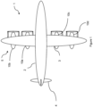
- an aircraft 1 is shown.
- the aircraft comprises a fuselage 2, wings 3, tail 4 and a propulsion system 5.
- the propulsion system comprises a plurality of propulsive gas turbine engines mounted to the wings 3 in pairs, with a first pair comprising an inboard gas turbine engine 10a and outboard gas turbine engine 10b provided on a port wing, and a second pair comprising an inboard gas turbine engine 10c and outboard gas turbine engine 10d provided on a starboard wing.
- Part of the propulsion system 5 is shown in detail in figure 2 .
- FIG. 2 shows the first gas turbine engine pair 10a, 10b schematically.
- the second pair of engines 10c, 10d are similar to the first pair.
- the gas turbine engine 10 works in the conventional manner so that air is accelerated by the respective fan 12a, 12b to produce two air flows: a first core air flow into the compressor 14a, 14b and a second air flow which bypasses the compressor 14a, 14b to provide propulsive thrust.
- the core air flows through the compressor 14a, 14b where it is compressed, before delivering that air to the combustion equipment 16a, 16b, where it is mixed with fuel and the mixture combusted.
- the resultant hot combustion products then expand through, and thereby drive, the turbines 18a, 18b, 20a, 20b before being exhausted through a nozzle to provide additional propulsive thrust.
- the high 18a, 18b and low-pressure turbines 20a, 20b, 20a, 20b drive respectively the compressor 14a, 14b and fan 12a, 12b, each by suitable high and low pressure interconnecting shaft 22a, 22b, 24a, 24b. Together, the low pressure turbine 20a, 20b, fan 12a, 12b and shaft 24a, 24b make up a low pressure spool, and the high pressure turbine 18a, 18b, compressor 14a, 14b and shaft 22a, 22b make up a high pressure spool.
- gas turbine engines to which the present disclosure may be applied may have alternative configurations.
- such engines may have an alternative number of interconnecting shafts (e.g. three) and/or an alternative number of compressors and/or turbines.
- a booster compressor may be coupled to the low pressure shaft 24a, 24b.
- the engine may comprise a gearbox provided in the drive train from a turbine to a compressor and/or fan.
- the ducted fan may be replaced by a propeller or unducted fan.
- the propulsion system 5 further comprises a plurality of electrical machines 32a, 32b.
- the inboard gas turbine engine 10a comprises an electrical machine 32a capable of operating at least as an electric generator
- the outboard gas turbine engine 10b comprises an electrical machine 32b capable of operating at least as an electric motor.
- Each electric machine 32a, 32b is of a conventional type, such as an induction or permanent magnet electric machine, and is coupled to a respective low-pressure shaft 24a, 24b.
- Each machine 32a, 32b comprises a stator comprising electrical windings (not shown), which can be energised to produce a rotating magnetic field (when used as a motor) and interact with a rotating magnetic field generated by a rotor to be energised to produce electric current (when operated as a generator). Consequently, the fan 12b may be powered by either or both of the gas turbine engine 10b via the low-pressure turbine 20b, and the motor 32b, while the turbine 20a of the gas turbine 10a drives the electric machine 32a to operate it as a generator.
- An electrical interconnector 34 is provided, which electrically couples the electric machines 32a, 32b to one another, to allow for power transfer at least from the inboard gas turbine engine 10a low pressure shaft 24a via the electric generator 32a, to the outboard gas turbine engine 10b low pressure shaft 24b via the electric motor 32b.
- each of the electric machines 32a, 32b may comprise motor / generators, capable of being operated as either motors or generators, such that power can be transferred between engines 10a, 10b in either direction.
- the controller 36 may comprise power electronics configured to accept AC electrical power generated by one of the electric machines at a first frequency, and convert this to AC power at a second frequency, to control both electric motor power, and rotational speed.
- the controller 36 may comprise power electronics configured to accept AC electrical power generated by one of the electric machines at a first frequency, and convert this to AC power at a second frequency, to control both electric motor power, and rotational speed.
- separate inverters and rectifiers may be provided.
- each of the machines 32a, 32b may comprise a DC machine, and the controller 36 may comprise a DC controller.
- the controller 36 is configured to modulate transfer of power in accordance with a signal received from an aircraft thrust controller 38.
- the aircraft thrust controller is operable to control a thrust generated from the engines 10a, 10b, and may comprise an aircraft throttle lever, autopilot, or auto-throttle.
- the controller 36 is operable to control the electric machines 32a, 32b to modulate power transfer between the engines 10a, 10b in accordance with a first operational method, as shown diagrammatically in figure 3 .
- aircraft and engine conditions are monitored.
- the aircraft conditions may comprise one or more of aircraft speed and altitude, and the engine conditions may comprise engine rotational speed or thrust setting.
- the controller 36 may only provide power transfer where the aircraft is determined to be in a cruise mode, i.e. is flying greater than a predetermined minimum altitude, and at greater than a predetermined speed, and between a maximum and minimum throttle setting.
- the controller 36 enables a power transfer mode.
- power transfer mode power transfer is adjusted where a thrust change demand is received from the thrust controller 38.
- power transfer mode may be selected by the pilot.
- a thrust increase is demanded from the thrust controller 38, for example, from a cruise thrust setting to a climb thrust setting
- power transfer is modulated.
- the electric machines 32a, 32b are controlled such that the electric machine 32a is operated as a generator, and the electric machine 32b is operated as an electric motor, such that increased power is transferred from the inboard gas turbine engine 10a low pressure shaft 24a to the outboard gas turbine 10b low pressure shaft 24b.
- both the engines 10a, 10b are controlled (by either the controllers 36 or 38) to increase power. Typically, this translates to an increased fuel flow demand. In response to the increased fuel flow, power of each engine 10a, 10b is increased.
- the response from each of the engines 10a, 10b to this increased fuel flow however differs, in view of the power transfer.
- the high-pressure spool (comprising compressor 14a, turbine 18a and shaft 22a) increases in speed.
- the low-pressure shaft 24a does not accelerate, accelerates to a relatively small degree, or may even decelerate.
- the controller 36 may be configured such that the low-pressure shaft 24 speed stays substantially constant with increasing thrust demand over a predetermined range of rotational speeds.
- the gas turbine engine 10a may comprise a low-pressure shaft speed sensor 40.
- the low-pressure shaft speed sensor 40 is coupled to the controller 36 as part of a closed loop control system, such as a PID controller. Power transfer between the engines 10a, 10b is then controlled on the basis of low-pressure shaft speed, such that generator 32a electrical output, and electric motor 32b power demand is controlled to maintain the low-pressure shaft speed of engine 10a at a predetermined set point, which may be a shaft speed prior to entering the power transfer mode, or may comprise a cruise thrust setting shaft speed. This speed may be maintained up to a predetermined power transfer limit.
- the power transfer limit may be set by one of an electric machine 32a, 32b maximum rating, or considerations of the gas turbine engine 10a, 10b operation. One such consideration may comprise minimum compressor 14a stall margin, or maximum fan 12b operating speed N1.
- the increased fuel flow results in increase high and low-pressure shaft 22b, 24b speed.
- low-pressure shaft speed increases to a greater degree than would be provided by the increased fuel flow alone, in view of the power injection to the low-pressure shaft 24b from the electric machine 32b operating as a motor. Consequently, fan 12b speed increases, resulting in increased thrust from the outboard engine 10b.
- Figure 4 illustrates the impact of this method on the overall thrust and the thrust contribution from the inboard and outboard engines.
- the increased thrust demand from the controller 38 results in increased thrust from the propulsion system 5 as a whole.
- the contribution to the thrust is not provided equally by all of the engines.
- the relatively unchanged rotational speed of the low-pressure spool of the inboard gas turbine engine 10a will result in relatively constant thrust from this engine, since the majority of thrust in high-bypass ratio gas turbine engines is generated by the fan flow, rather than core flow.
- the high-pressure spool may accelerate, but since core flow represents a relatively small proportion of overall thrust, the any net thrust increase will be small.
- the resultant increase in rotational speed of the low-pressure spool of the outboard engines 10b results in an increase in noise level generated by those engines, in view of the increased mass flow and bypass jet velocity produced by the fan.
- a majority of the noise generated in flight is generated by the fan flow, rather than core flow, since the core flow is shielded by the fan flow and to an extent by the nacelle.
- the resultant increase in rotational speed of the outboard engines 10b, 10d relative to the inboard engines 10a, 10c results in a relatively small increase in noise perceived by the passengers onboard the aircraft 1. This is because the outboard engines are located further from the fuselage 2 (and therefore further from the passengers) than the inboard engines. Consequently, the overall noise perceived by passengers is reduced relative to conventional propulsion systems.
- the system is also operable in accordance with further methods.
- Figure 6 illustrates a second method of operation of the propulsion system 5.
- power is to be transferred from the outboard engine 10b, 10d, to the inboard engines 10a, 10c. Consequently, the electric machine 32b is configured to operate as a generator, and the electric machine 32a is configured to operate as a motor.
- the aircraft determines whether aircraft and engine conditions are met to enable power transfer mode.
- the system may comprise a step to determine that a thrust increase is requested, but the application of increased thrust can be delayed.
- the aircraft autopilot may indicate that a flight level change is required.
- a "pre-acceleration" method of operating is then imposed.
- the level of power transferred between the engines is gradually increased in advance of the thrust change, while maintaining overall thrust levels.
- the controller 38 is configured to set a substantially constant fuel flow demand to the inboard and outboard engines 10a-d.
- the controller 36 controls the electric machine 32b to operate as a generator, and to operate the electric machine 32a as a motor, to thereby transfer power from the outboard engine 10b to the inboard engine 10a. Consequently, inboard engine thrust increases, while outboard engine thrust decreases, in view of the accelerating low-pressure spool on the inboard engines 10a, 10c, and decelerating low-pressure spool on the outboard engines 10b, 10d.
- Fuel flow may be slightly increased on some or all engines to maintain overall engine thrust, in view of inefficiencies of the power transfer system.
- the power transfer magnitude is increased gradually on the basis of a set schedule, which in turn results in gradually increasing inboard engine thrust, and gradually decreasing outboard engine thrust, as shown in figure 6 .
- the system may utilise respective low-pressure speed sensors 40a, 40b to control the rotational speed of each engine 10a, 10b. As the rotational speed setpoint is increased over time, power transfer is modulated by the controller 36 to maintain the low-pressure shaft speed at the set point.
- the engines are operated in the acceleration mode, as outlined previously. In this mode, fuel flow to all engines 10a-d is increased. Simultaneously, the direction of power transfer is reversed, with power being transferred from the inboard engines to the outboard engines. The result is a relatively constant or only slight increase in inboard engine speed, while the outboard engines accelerate rapidly. Again, this will result in reduced noise perceived by the passengers aboard the aircraft.
- the engines are operated in accordance with a deceleration mode, in which the engines power transfer direction is again reversed, such that the power is transferred from the outboard engines to the inboard engines.
- fuel is rapidly reduced to each engine, such that high-pressure spool speed falls rapidly.
- the magnitude of power transfer is gradually reduced, to slowly decelerate the inboard engines.
- a similar process can be operated in reverse, when decelerating the engines, such as when transitioning from top-of climb to cruise or from step-climb to cruise, or from cruise to top-of-descent.
- Such a method may reduce the rapid pitch change in noise level generated by the engines when transitioning from cruise to climb, and thereby reduce perceived noise and discomfort for passengers.
- the disclosed arrangement and method can also be applied to aircraft having different configurations.
- the aircraft may comprise a three-engine aircraft, such as the aircraft 101 shown in figure 7 .
- the aircraft 101 is similar to the aircraft 1, comprising a fuselage 102, wings 103 and a tail 104.
- the aircraft comprises a propulsion system 105 which differs from the system 5 in terms of the locations of the engines.
- the propulsion system comprises a pair of wing-mounted engines 110a, 110c. additionally, a third engine 110b is provided at a centreline of the aircraft in the tail 104. in this case, the tail mounted engine 110b forms the inboard engine, while the two wing-mounted engines form the outboard engines.
- Each engine 110a-c is similar to the engines 10a-c of the first embodiment, and each comprise respective electric machines (not shown).
- An electrical interconnector 134 is provided between the inboard engine 110b and outboard engines 110a,c.
- the propulsion system 105 is operated in a similar manner to the propulsion system 5 as described above, with transfer of electrical power being made during thrust setting changes.
- different numbers of engines could be used, such as five or six engines.
- Different engine configurations could be utilised, with generators and motors being provided coupled to different shafts.
- the engines could be provided in different locations on the aircraft. For instance, all engines could be located at the tail, or engines could be distributed about the aircraft.
- the engines could be in the form of turbofan engines, having a fan surrounded by a nacelle, or in the form of open rotor / turboprop engines, having propellers with no surrounding nacelle.
Landscapes
- Engineering & Computer Science (AREA)
- Aviation & Aerospace Engineering (AREA)
- Chemical & Material Sciences (AREA)
- Combustion & Propulsion (AREA)
- Mechanical Engineering (AREA)
- General Engineering & Computer Science (AREA)
- Engine Equipment That Uses Special Cycles (AREA)
Applications Claiming Priority (1)
| Application Number | Priority Date | Filing Date | Title |
|---|---|---|---|
| GBGB2113728.6A GB202113728D0 (en) | 2021-09-27 | 2021-09-27 | Aircraft hybrid propulsion system |
Publications (2)
| Publication Number | Publication Date |
|---|---|
| EP4155212A1 true EP4155212A1 (de) | 2023-03-29 |
| EP4155212B1 EP4155212B1 (de) | 2024-06-19 |
Family
ID=78399616
Family Applications (1)
| Application Number | Title | Priority Date | Filing Date |
|---|---|---|---|
| EP22192722.1A Active EP4155212B1 (de) | 2021-09-27 | 2022-08-30 | Flugzeughybridantriebssystem |
Country Status (3)
| Country | Link |
|---|---|
| US (1) | US12043395B2 (de) |
| EP (1) | EP4155212B1 (de) |
| GB (1) | GB202113728D0 (de) |
Citations (3)
| Publication number | Priority date | Publication date | Assignee | Title |
|---|---|---|---|---|
| US20100083632A1 (en) * | 2008-10-08 | 2010-04-08 | Searete Llc, A Limited Liability Corporation Of The State Of Delaware | Hybrid propulsive engine including at least one independently rotatable compressor rotor |
| EP3360783A1 (de) * | 2017-02-10 | 2018-08-15 | General Electric Company | Antriebssystem für ein flugzeug |
| EP3650351A1 (de) * | 2018-11-08 | 2020-05-13 | Rolls-Royce North American Technologies, Inc. | Elektrische architektur für hybridantrieb |
Family Cites Families (3)
| Publication number | Priority date | Publication date | Assignee | Title |
|---|---|---|---|---|
| US6880784B1 (en) * | 2003-05-08 | 2005-04-19 | Supersonic Aerospace International, Llc | Automatic takeoff thrust management system |
| US20100126178A1 (en) * | 2008-10-08 | 2010-05-27 | Searete Llc, A Limited Liability Corporation Of The State Of Delaware | Hybrid propulsive engine including at least one independently rotatable turbine stator |
| US20230150681A1 (en) * | 2021-11-15 | 2023-05-18 | General Electric Company | Gas turbine engine noise reduction |
-
2021
- 2021-09-27 GB GBGB2113728.6A patent/GB202113728D0/en not_active Ceased
-
2022
- 2022-08-30 EP EP22192722.1A patent/EP4155212B1/de active Active
- 2022-09-09 US US17/941,374 patent/US12043395B2/en active Active
Patent Citations (3)
| Publication number | Priority date | Publication date | Assignee | Title |
|---|---|---|---|---|
| US20100083632A1 (en) * | 2008-10-08 | 2010-04-08 | Searete Llc, A Limited Liability Corporation Of The State Of Delaware | Hybrid propulsive engine including at least one independently rotatable compressor rotor |
| EP3360783A1 (de) * | 2017-02-10 | 2018-08-15 | General Electric Company | Antriebssystem für ein flugzeug |
| EP3650351A1 (de) * | 2018-11-08 | 2020-05-13 | Rolls-Royce North American Technologies, Inc. | Elektrische architektur für hybridantrieb |
Also Published As
| Publication number | Publication date |
|---|---|
| GB202113728D0 (en) | 2021-11-10 |
| US20230101578A1 (en) | 2023-03-30 |
| US12043395B2 (en) | 2024-07-23 |
| EP4155212B1 (de) | 2024-06-19 |
Similar Documents
| Publication | Publication Date | Title |
|---|---|---|
| EP3556659B1 (de) | Hybridantriebsmotoren für flugzeuge | |
| CA3009019C (en) | Propulsion system for an aircraft | |
| US11174035B2 (en) | Hybrid flight vehicle | |
| CN102245878B (zh) | 包括至少一个可独立旋转的压缩机转子的混合推进发动机 | |
| US8857191B2 (en) | Hybrid propulsive engine including at least one independently rotatable propeller/fan | |
| CN113264194B (zh) | 飞机的额外推力控制 | |
| US10710734B2 (en) | Hybrid aircraft propulsors having electrically-driven augmentor fans | |
| US20100126178A1 (en) | Hybrid propulsive engine including at least one independently rotatable turbine stator | |
| EP3798129A1 (de) | Elektromotor für einen propellerantrieb | |
| GB2539756A (en) | Aircraft propulsion system | |
| US12577906B2 (en) | Electrical power system for a vehicle | |
| EP4155211B1 (de) | Flugzeugantriebssystem | |
| EP4155212A1 (de) | Flugzeughybridantriebssystem | |
| US12275313B2 (en) | Propulsion system of aircraft | |
| US12368359B2 (en) | Electrical energy system having active segments for variable voltage generation |
Legal Events
| Date | Code | Title | Description |
|---|---|---|---|
| PUAI | Public reference made under article 153(3) epc to a published international application that has entered the european phase |
Free format text: ORIGINAL CODE: 0009012 |
|
| STAA | Information on the status of an ep patent application or granted ep patent |
Free format text: STATUS: THE APPLICATION HAS BEEN PUBLISHED |
|
| AK | Designated contracting states |
Kind code of ref document: A1 Designated state(s): AL AT BE BG CH CY CZ DE DK EE ES FI FR GB GR HR HU IE IS IT LI LT LU LV MC MK MT NL NO PL PT RO RS SE SI SK SM TR |
|
| STAA | Information on the status of an ep patent application or granted ep patent |
Free format text: STATUS: REQUEST FOR EXAMINATION WAS MADE |
|
| 17P | Request for examination filed |
Effective date: 20230522 |
|
| RBV | Designated contracting states (corrected) |
Designated state(s): AL AT BE BG CH CY CZ DE DK EE ES FI FR GB GR HR HU IE IS IT LI LT LU LV MC MK MT NL NO PL PT RO RS SE SI SK SM TR |
|
| GRAP | Despatch of communication of intention to grant a patent |
Free format text: ORIGINAL CODE: EPIDOSNIGR1 |
|
| STAA | Information on the status of an ep patent application or granted ep patent |
Free format text: STATUS: GRANT OF PATENT IS INTENDED |
|
| GRAS | Grant fee paid |
Free format text: ORIGINAL CODE: EPIDOSNIGR3 |
|
| INTG | Intention to grant announced |
Effective date: 20240415 |
|
| GRAA | (expected) grant |
Free format text: ORIGINAL CODE: 0009210 |
|
| STAA | Information on the status of an ep patent application or granted ep patent |
Free format text: STATUS: THE PATENT HAS BEEN GRANTED |
|
| P01 | Opt-out of the competence of the unified patent court (upc) registered |
Effective date: 20240424 |
|
| AK | Designated contracting states |
Kind code of ref document: B1 Designated state(s): AL AT BE BG CH CY CZ DE DK EE ES FI FR GB GR HR HU IE IS IT LI LT LU LV MC MK MT NL NO PL PT RO RS SE SI SK SM TR |
|
| REG | Reference to a national code |
Ref country code: GB Ref legal event code: FG4D |
|
| REG | Reference to a national code |
Ref country code: CH Ref legal event code: EP |
|
| REG | Reference to a national code |
Ref country code: DE Ref legal event code: R096 Ref document number: 602022004015 Country of ref document: DE |
|
| PG25 | Lapsed in a contracting state [announced via postgrant information from national office to epo] |
Ref country code: BG Free format text: LAPSE BECAUSE OF FAILURE TO SUBMIT A TRANSLATION OF THE DESCRIPTION OR TO PAY THE FEE WITHIN THE PRESCRIBED TIME-LIMIT Effective date: 20240619 |
|
| PG25 | Lapsed in a contracting state [announced via postgrant information from national office to epo] |
Ref country code: FI Free format text: LAPSE BECAUSE OF FAILURE TO SUBMIT A TRANSLATION OF THE DESCRIPTION OR TO PAY THE FEE WITHIN THE PRESCRIBED TIME-LIMIT Effective date: 20240619 Ref country code: HR Free format text: LAPSE BECAUSE OF FAILURE TO SUBMIT A TRANSLATION OF THE DESCRIPTION OR TO PAY THE FEE WITHIN THE PRESCRIBED TIME-LIMIT Effective date: 20240619 |
|
| REG | Reference to a national code |
Ref country code: LT Ref legal event code: MG9D |
|
| PG25 | Lapsed in a contracting state [announced via postgrant information from national office to epo] |
Ref country code: GR Free format text: LAPSE BECAUSE OF FAILURE TO SUBMIT A TRANSLATION OF THE DESCRIPTION OR TO PAY THE FEE WITHIN THE PRESCRIBED TIME-LIMIT Effective date: 20240920 |
|
| REG | Reference to a national code |
Ref country code: NL Ref legal event code: MP Effective date: 20240619 |
|
| PG25 | Lapsed in a contracting state [announced via postgrant information from national office to epo] |
Ref country code: LV Free format text: LAPSE BECAUSE OF FAILURE TO SUBMIT A TRANSLATION OF THE DESCRIPTION OR TO PAY THE FEE WITHIN THE PRESCRIBED TIME-LIMIT Effective date: 20240619 |
|
| PG25 | Lapsed in a contracting state [announced via postgrant information from national office to epo] |
Ref country code: NO Free format text: LAPSE BECAUSE OF FAILURE TO SUBMIT A TRANSLATION OF THE DESCRIPTION OR TO PAY THE FEE WITHIN THE PRESCRIBED TIME-LIMIT Effective date: 20240919 Ref country code: LV Free format text: LAPSE BECAUSE OF FAILURE TO SUBMIT A TRANSLATION OF THE DESCRIPTION OR TO PAY THE FEE WITHIN THE PRESCRIBED TIME-LIMIT Effective date: 20240619 Ref country code: HR Free format text: LAPSE BECAUSE OF FAILURE TO SUBMIT A TRANSLATION OF THE DESCRIPTION OR TO PAY THE FEE WITHIN THE PRESCRIBED TIME-LIMIT Effective date: 20240619 Ref country code: GR Free format text: LAPSE BECAUSE OF FAILURE TO SUBMIT A TRANSLATION OF THE DESCRIPTION OR TO PAY THE FEE WITHIN THE PRESCRIBED TIME-LIMIT Effective date: 20240920 Ref country code: FI Free format text: LAPSE BECAUSE OF FAILURE TO SUBMIT A TRANSLATION OF THE DESCRIPTION OR TO PAY THE FEE WITHIN THE PRESCRIBED TIME-LIMIT Effective date: 20240619 Ref country code: BG Free format text: LAPSE BECAUSE OF FAILURE TO SUBMIT A TRANSLATION OF THE DESCRIPTION OR TO PAY THE FEE WITHIN THE PRESCRIBED TIME-LIMIT Effective date: 20240619 Ref country code: RS Free format text: LAPSE BECAUSE OF FAILURE TO SUBMIT A TRANSLATION OF THE DESCRIPTION OR TO PAY THE FEE WITHIN THE PRESCRIBED TIME-LIMIT Effective date: 20240919 |
|
| PG25 | Lapsed in a contracting state [announced via postgrant information from national office to epo] |
Ref country code: NL Free format text: LAPSE BECAUSE OF FAILURE TO SUBMIT A TRANSLATION OF THE DESCRIPTION OR TO PAY THE FEE WITHIN THE PRESCRIBED TIME-LIMIT Effective date: 20240619 |
|
| REG | Reference to a national code |
Ref country code: AT Ref legal event code: MK05 Ref document number: 1695787 Country of ref document: AT Kind code of ref document: T Effective date: 20240619 |
|
| PG25 | Lapsed in a contracting state [announced via postgrant information from national office to epo] |
Ref country code: NL Free format text: LAPSE BECAUSE OF FAILURE TO SUBMIT A TRANSLATION OF THE DESCRIPTION OR TO PAY THE FEE WITHIN THE PRESCRIBED TIME-LIMIT Effective date: 20240619 |
|
| PG25 | Lapsed in a contracting state [announced via postgrant information from national office to epo] |
Ref country code: PT Free format text: LAPSE BECAUSE OF FAILURE TO SUBMIT A TRANSLATION OF THE DESCRIPTION OR TO PAY THE FEE WITHIN THE PRESCRIBED TIME-LIMIT Effective date: 20241021 |
|
| PG25 | Lapsed in a contracting state [announced via postgrant information from national office to epo] |
Ref country code: PT Free format text: LAPSE BECAUSE OF FAILURE TO SUBMIT A TRANSLATION OF THE DESCRIPTION OR TO PAY THE FEE WITHIN THE PRESCRIBED TIME-LIMIT Effective date: 20241021 |
|
| PG25 | Lapsed in a contracting state [announced via postgrant information from national office to epo] |
Ref country code: PL Free format text: LAPSE BECAUSE OF FAILURE TO SUBMIT A TRANSLATION OF THE DESCRIPTION OR TO PAY THE FEE WITHIN THE PRESCRIBED TIME-LIMIT Effective date: 20240619 |
|
| PG25 | Lapsed in a contracting state [announced via postgrant information from national office to epo] |
Ref country code: EE Free format text: LAPSE BECAUSE OF FAILURE TO SUBMIT A TRANSLATION OF THE DESCRIPTION OR TO PAY THE FEE WITHIN THE PRESCRIBED TIME-LIMIT Effective date: 20240619 |
|
| PG25 | Lapsed in a contracting state [announced via postgrant information from national office to epo] |
Ref country code: IS Free format text: LAPSE BECAUSE OF FAILURE TO SUBMIT A TRANSLATION OF THE DESCRIPTION OR TO PAY THE FEE WITHIN THE PRESCRIBED TIME-LIMIT Effective date: 20241019 Ref country code: AT Free format text: LAPSE BECAUSE OF FAILURE TO SUBMIT A TRANSLATION OF THE DESCRIPTION OR TO PAY THE FEE WITHIN THE PRESCRIBED TIME-LIMIT Effective date: 20240619 |
|
| PG25 | Lapsed in a contracting state [announced via postgrant information from national office to epo] |
Ref country code: CZ Free format text: LAPSE BECAUSE OF FAILURE TO SUBMIT A TRANSLATION OF THE DESCRIPTION OR TO PAY THE FEE WITHIN THE PRESCRIBED TIME-LIMIT Effective date: 20240619 |
|
| PG25 | Lapsed in a contracting state [announced via postgrant information from national office to epo] |
Ref country code: RO Free format text: LAPSE BECAUSE OF FAILURE TO SUBMIT A TRANSLATION OF THE DESCRIPTION OR TO PAY THE FEE WITHIN THE PRESCRIBED TIME-LIMIT Effective date: 20240619 Ref country code: SK Free format text: LAPSE BECAUSE OF FAILURE TO SUBMIT A TRANSLATION OF THE DESCRIPTION OR TO PAY THE FEE WITHIN THE PRESCRIBED TIME-LIMIT Effective date: 20240619 |
|
| PG25 | Lapsed in a contracting state [announced via postgrant information from national office to epo] |
Ref country code: SM Free format text: LAPSE BECAUSE OF FAILURE TO SUBMIT A TRANSLATION OF THE DESCRIPTION OR TO PAY THE FEE WITHIN THE PRESCRIBED TIME-LIMIT Effective date: 20240619 Ref country code: ES Free format text: LAPSE BECAUSE OF FAILURE TO SUBMIT A TRANSLATION OF THE DESCRIPTION OR TO PAY THE FEE WITHIN THE PRESCRIBED TIME-LIMIT Effective date: 20240619 |
|
| PG25 | Lapsed in a contracting state [announced via postgrant information from national office to epo] |
Ref country code: SM Free format text: LAPSE BECAUSE OF FAILURE TO SUBMIT A TRANSLATION OF THE DESCRIPTION OR TO PAY THE FEE WITHIN THE PRESCRIBED TIME-LIMIT Effective date: 20240619 Ref country code: SK Free format text: LAPSE BECAUSE OF FAILURE TO SUBMIT A TRANSLATION OF THE DESCRIPTION OR TO PAY THE FEE WITHIN THE PRESCRIBED TIME-LIMIT Effective date: 20240619 Ref country code: RO Free format text: LAPSE BECAUSE OF FAILURE TO SUBMIT A TRANSLATION OF THE DESCRIPTION OR TO PAY THE FEE WITHIN THE PRESCRIBED TIME-LIMIT Effective date: 20240619 Ref country code: PL Free format text: LAPSE BECAUSE OF FAILURE TO SUBMIT A TRANSLATION OF THE DESCRIPTION OR TO PAY THE FEE WITHIN THE PRESCRIBED TIME-LIMIT Effective date: 20240619 Ref country code: IS Free format text: LAPSE BECAUSE OF FAILURE TO SUBMIT A TRANSLATION OF THE DESCRIPTION OR TO PAY THE FEE WITHIN THE PRESCRIBED TIME-LIMIT Effective date: 20241019 Ref country code: ES Free format text: LAPSE BECAUSE OF FAILURE TO SUBMIT A TRANSLATION OF THE DESCRIPTION OR TO PAY THE FEE WITHIN THE PRESCRIBED TIME-LIMIT Effective date: 20240619 Ref country code: EE Free format text: LAPSE BECAUSE OF FAILURE TO SUBMIT A TRANSLATION OF THE DESCRIPTION OR TO PAY THE FEE WITHIN THE PRESCRIBED TIME-LIMIT Effective date: 20240619 Ref country code: CZ Free format text: LAPSE BECAUSE OF FAILURE TO SUBMIT A TRANSLATION OF THE DESCRIPTION OR TO PAY THE FEE WITHIN THE PRESCRIBED TIME-LIMIT Effective date: 20240619 Ref country code: AT Free format text: LAPSE BECAUSE OF FAILURE TO SUBMIT A TRANSLATION OF THE DESCRIPTION OR TO PAY THE FEE WITHIN THE PRESCRIBED TIME-LIMIT Effective date: 20240619 |
|
| PG25 | Lapsed in a contracting state [announced via postgrant information from national office to epo] |
Ref country code: IT Free format text: LAPSE BECAUSE OF FAILURE TO SUBMIT A TRANSLATION OF THE DESCRIPTION OR TO PAY THE FEE WITHIN THE PRESCRIBED TIME-LIMIT Effective date: 20240619 |
|
| REG | Reference to a national code |
Ref country code: DE Ref legal event code: R097 Ref document number: 602022004015 Country of ref document: DE |
|
| PG25 | Lapsed in a contracting state [announced via postgrant information from national office to epo] |
Ref country code: DK Free format text: LAPSE BECAUSE OF FAILURE TO SUBMIT A TRANSLATION OF THE DESCRIPTION OR TO PAY THE FEE WITHIN THE PRESCRIBED TIME-LIMIT Effective date: 20240619 |
|
| PG25 | Lapsed in a contracting state [announced via postgrant information from national office to epo] |
Ref country code: LU Free format text: LAPSE BECAUSE OF NON-PAYMENT OF DUE FEES Effective date: 20240830 |
|
| PG25 | Lapsed in a contracting state [announced via postgrant information from national office to epo] |
Ref country code: MC Free format text: LAPSE BECAUSE OF FAILURE TO SUBMIT A TRANSLATION OF THE DESCRIPTION OR TO PAY THE FEE WITHIN THE PRESCRIBED TIME-LIMIT Effective date: 20240619 |
|
| PLBE | No opposition filed within time limit |
Free format text: ORIGINAL CODE: 0009261 |
|
| STAA | Information on the status of an ep patent application or granted ep patent |
Free format text: STATUS: NO OPPOSITION FILED WITHIN TIME LIMIT |
|
| 26N | No opposition filed |
Effective date: 20250320 |
|
| REG | Reference to a national code |
Ref country code: BE Ref legal event code: MM Effective date: 20240831 |
|
| PG25 | Lapsed in a contracting state [announced via postgrant information from national office to epo] |
Ref country code: BE Free format text: LAPSE BECAUSE OF NON-PAYMENT OF DUE FEES Effective date: 20240831 |
|
| PG25 | Lapsed in a contracting state [announced via postgrant information from national office to epo] |
Ref country code: IE Free format text: LAPSE BECAUSE OF NON-PAYMENT OF DUE FEES Effective date: 20240830 |
|
| PG25 | Lapsed in a contracting state [announced via postgrant information from national office to epo] |
Ref country code: SE Free format text: LAPSE BECAUSE OF FAILURE TO SUBMIT A TRANSLATION OF THE DESCRIPTION OR TO PAY THE FEE WITHIN THE PRESCRIBED TIME-LIMIT Effective date: 20240619 |
|
| PGFP | Annual fee paid to national office [announced via postgrant information from national office to epo] |
Ref country code: DE Payment date: 20250827 Year of fee payment: 4 |
|
| PGFP | Annual fee paid to national office [announced via postgrant information from national office to epo] |
Ref country code: FR Payment date: 20250825 Year of fee payment: 4 |
|
| PG25 | Lapsed in a contracting state [announced via postgrant information from national office to epo] |
Ref country code: CY Free format text: LAPSE BECAUSE OF FAILURE TO SUBMIT A TRANSLATION OF THE DESCRIPTION OR TO PAY THE FEE WITHIN THE PRESCRIBED TIME-LIMIT; INVALID AB INITIO Effective date: 20220830 |
|
| PG25 | Lapsed in a contracting state [announced via postgrant information from national office to epo] |
Ref country code: HU Free format text: LAPSE BECAUSE OF FAILURE TO SUBMIT A TRANSLATION OF THE DESCRIPTION OR TO PAY THE FEE WITHIN THE PRESCRIBED TIME-LIMIT; INVALID AB INITIO Effective date: 20220830 |
|
| REG | Reference to a national code |
Ref country code: CH Ref legal event code: H13 Free format text: ST27 STATUS EVENT CODE: U-0-0-H10-H13 (AS PROVIDED BY THE NATIONAL OFFICE) Effective date: 20260324 |
|
| PG25 | Lapsed in a contracting state [announced via postgrant information from national office to epo] |
Ref country code: CH Free format text: LAPSE BECAUSE OF NON-PAYMENT OF DUE FEES Effective date: 20250831 |