EP4155228A1 - Ensemble d'emballage - Google Patents
Ensemble d'emballage Download PDFInfo
- Publication number
- EP4155228A1 EP4155228A1 EP22197231.8A EP22197231A EP4155228A1 EP 4155228 A1 EP4155228 A1 EP 4155228A1 EP 22197231 A EP22197231 A EP 22197231A EP 4155228 A1 EP4155228 A1 EP 4155228A1
- Authority
- EP
- European Patent Office
- Prior art keywords
- cover
- base
- packaging assembly
- assembly according
- item
- Prior art date
- Legal status (The legal status is an assumption and is not a legal conclusion. Google has not performed a legal analysis and makes no representation as to the accuracy of the status listed.)
- Granted
Links
Images


Classifications
-
- B—PERFORMING OPERATIONS; TRANSPORTING
- B65—CONVEYING; PACKING; STORING; HANDLING THIN OR FILAMENTARY MATERIAL
- B65D—CONTAINERS FOR STORAGE OR TRANSPORT OF ARTICLES OR MATERIALS, e.g. BAGS, BARRELS, BOTTLES, BOXES, CANS, CARTONS, CRATES, DRUMS, JARS, TANKS, HOPPERS, FORWARDING CONTAINERS; ACCESSORIES, CLOSURES, OR FITTINGS THEREFOR; PACKAGING ELEMENTS; PACKAGES
- B65D81/00—Containers, packaging elements, or packages, for contents presenting particular transport or storage problems, or adapted to be used for non-packaging purposes after removal of contents
- B65D81/02—Containers, packaging elements, or packages, for contents presenting particular transport or storage problems, or adapted to be used for non-packaging purposes after removal of contents specially adapted to protect contents from mechanical damage
- B65D81/05—Containers, packaging elements, or packages, for contents presenting particular transport or storage problems, or adapted to be used for non-packaging purposes after removal of contents specially adapted to protect contents from mechanical damage maintaining contents at spaced relation from package walls, or from other contents
- B65D81/051—Containers, packaging elements, or packages, for contents presenting particular transport or storage problems, or adapted to be used for non-packaging purposes after removal of contents specially adapted to protect contents from mechanical damage maintaining contents at spaced relation from package walls, or from other contents using pillow-like elements filled with cushioning material, e.g. elastic foam, fabric
- B65D81/052—Containers, packaging elements, or packages, for contents presenting particular transport or storage problems, or adapted to be used for non-packaging purposes after removal of contents specially adapted to protect contents from mechanical damage maintaining contents at spaced relation from package walls, or from other contents using pillow-like elements filled with cushioning material, e.g. elastic foam, fabric filled with fluid, e.g. inflatable elements
-
- B—PERFORMING OPERATIONS; TRANSPORTING
- B65—CONVEYING; PACKING; STORING; HANDLING THIN OR FILAMENTARY MATERIAL
- B65D—CONTAINERS FOR STORAGE OR TRANSPORT OF ARTICLES OR MATERIALS, e.g. BAGS, BARRELS, BOTTLES, BOXES, CANS, CARTONS, CRATES, DRUMS, JARS, TANKS, HOPPERS, FORWARDING CONTAINERS; ACCESSORIES, CLOSURES, OR FITTINGS THEREFOR; PACKAGING ELEMENTS; PACKAGES
- B65D65/00—Wrappers or flexible covers; Packaging materials of special type or form
- B65D65/02—Wrappers or flexible covers
- B65D65/04—Wrappers or flexible covers non-rectangular
- B65D65/08—Wrappers or flexible covers non-rectangular with fastening elements, e.g. slide fasteners
-
- B—PERFORMING OPERATIONS; TRANSPORTING
- B65—CONVEYING; PACKING; STORING; HANDLING THIN OR FILAMENTARY MATERIAL
- B65D—CONTAINERS FOR STORAGE OR TRANSPORT OF ARTICLES OR MATERIALS, e.g. BAGS, BARRELS, BOTTLES, BOXES, CANS, CARTONS, CRATES, DRUMS, JARS, TANKS, HOPPERS, FORWARDING CONTAINERS; ACCESSORIES, CLOSURES, OR FITTINGS THEREFOR; PACKAGING ELEMENTS; PACKAGES
- B65D85/00—Containers, packaging elements or packages, specially adapted for particular articles or materials
- B65D85/64—Containers, packaging elements or packages, specially adapted for particular articles or materials for bulky articles
-
- B—PERFORMING OPERATIONS; TRANSPORTING
- B65—CONVEYING; PACKING; STORING; HANDLING THIN OR FILAMENTARY MATERIAL
- B65D—CONTAINERS FOR STORAGE OR TRANSPORT OF ARTICLES OR MATERIALS, e.g. BAGS, BARRELS, BOTTLES, BOXES, CANS, CARTONS, CRATES, DRUMS, JARS, TANKS, HOPPERS, FORWARDING CONTAINERS; ACCESSORIES, CLOSURES, OR FITTINGS THEREFOR; PACKAGING ELEMENTS; PACKAGES
- B65D2585/00—Containers, packaging elements or packages specially adapted for particular articles or materials
- B65D2585/64—Containers, packaging elements or packages specially adapted for particular articles or materials for bulky articles
- B65D2585/641—Containers, packaging elements or packages specially adapted for particular articles or materials for bulky articles specific articles
- B65D2585/647—Containers, packaging elements or packages specially adapted for particular articles or materials for bulky articles specific articles furniture
Definitions
- the present disclosure relates to a packaging assembly for protecting an item in transit.
- the packaging assembly may be particularly, but not exclusively, useful for the transport of large items, such as furniture.
- such packaging When transporting large items that are susceptible to damage, such as furniture, it is known to provide protective packaging around the item to prevent damage to the item.
- packaging includes one or more of plastic sheeting (or a plastic bag), cardboard (such as a cardboard box) and polystyrene foam.
- plastic sheeting or a plastic bag
- cardboard such as a cardboard box
- polystyrene foam For items that are a non-cuboid shape (i.e. that don't fit neatly into a box) a large number of complicated inserts may be required to limit movement of the item within the box (and to provide shock absorption). This can make such packaging relatively complex.
- the item On arrival at the destination, the item is typically removed from the packaging by e.g. cutting through the carboard and/or plastic and removing various polystyrene foam pieces positioned about the item.
- This unpacking process can take a significant amount of time and typically the packaging is left in a state that makes it unsuitable for further use (so that it must then be disposed).
- the inability to reuse the packaging has implications for both the environment and operational costs.
- carboard the limited durability of carboard means that it is susceptible to damage during transit. This can, in some cases, result in damage to the packaged item. It also means that even if the packaging is intended for reuse it will typically have a very limited life span.
- a packaging assembly for protecting an item in transit comprising:
- an inflatable cover can provide increased protection of an item in transit (e.g. when compared to the use of cardboard). Further, the cover is able to provide the dual functionality of absorbing shock (via the inflatable compartments) and preventing direct contact of the item with e.g. sharp objects (via the skin). This reduces the number of components required to package an item (for example, cardboard is often paired with polystyrene foam for shock absorption). This, in turn, reduces the complexity of the packaging assembly and makes packing/unpacking of items easier. One result of this is that the packaging assembly is less likely to experience damage during packing/unpacking, which means it is more suitable for reuse.
- the cover is also able to conform (due to the flexibility of the skin) to the shape of the item, which means that the packaging assembly can be used with a variety of items of different shape (again making it particularly suited for reuse). Moreover, by conforming to the item, the cover may help to retain an item within the item-receiving space in use.
- the base may be rigid.
- the base may have greater rigidity than the cover.
- the base may be self-supporting (i.e. may maintain its shape when carried).
- the base may comprise a rigid body (e.g. removably) received in a sleeve (to which the cover may be securable).
- the sleeve may be flexible (and may be formed of a plastic, such as PVC).
- the sleeve may for example, comprise a closable opening (e.g. closable by a zip or other fastening means) that allows insertion and removal of the rigid body.
- the provision of an openable sleeve means that the rigid body may be replaced as necessary (e.g. due to damage or deterioration during use).
- the rigid body may comprise cardboard (for example may comprise cardboard formed in a hexacomb structure).
- the base may comprise polystyrene.
- the base may be planar.
- a bottom surface of the base may be planar.
- a top surface of the base may be planar.
- the cover may comprise two edge portions secured to opposite edges of the base.
- the base may be rectangular.
- the cover may comprise two edge portions secured to opposing longitudinal edges (i.e. the long edges) of the base, e.g. when it is rectangular.
- the base may be other than rectangular, for example the base may be circular, elliptical, triangular, hexagonal, obround, etc.
- the base may comprise retaining means for retaining an item on the base.
- the retaining means may, for example, comprise one or more ties or straps for retaining the item. At least one end of each tie or strap may be secured to the base, such as to the sleeve of the base when present.
- the or each tie or strap may be formed of webbing.
- the packaging assembly may be configurable between a closed position and an open position. In the closed position the intermediate portion of the cover may extend over the base and in the open position the intermediate portion of the cover may not extend over the base (such that access is provided to the base).
- the open position may be enabled by configuring at least one of the edge portions so as to be releasably securable to the base.
- the at least one edge portion may be released from the base and moved away from the base (so as define a free edge of the cover) to configure the packaging assembly in the open position.
- the open position may be enabled by providing the cover with a plurality of cover portions that are separable from one another so as to be able to move between the closed and open position.
- the cover may comprise first and second cover portions that are secured to one another in the closed position and that are at least partly separated from one another in the open position.
- Each of the first and second cover portions may comprise one of the edge portions of the cover (securable to the base) and an opposite free edge that is releasably secured to the free edge of the other cover portion in the closed position (and at least partly separated therefrom in the open position).
- the first and second cover portions may join (separably) along a join line, which may extend parallel to an elongate axis of the cover.
- the join line may be equidistantly interposed between the edge portions (i.e. may extend centrally across the intermediate portion).
- the cover may have a clamshell form.
- the cover may only comprise two cover portions (the first and second cover portions). In other embodiments, the cover may comprise further cover portions, for example third and fourth cover portions (e.g. each may have an edge portion securable to the base and an opposite free edge that may be securable to one or more of the other cover portions).
- the cover may have a cuboid shape (in the closed position) and the cover portions may define sidewalls of the cuboidal shape (i.e. the sidewalls upstanding from the base). At least one of the cover portions may define a lid of the cover.
- one or more of the cover portions may be releasably secured to adjacent sidewalls along lateral edges of the cover portion (extending upwardly from the base in the closed position). This may be provided, for example, by tabs extending along the lateral edges.
- the cover may be configured so as to have at least one free edge that is movable away from the base when in the open position (e.g. the free edge being releasably securable to the base in embodiments where the cover is single piece or to another cover portion in embodiments where the cover is formed of at least two cover portions).
- the free edge may be releasably securable (e.g. to the other cover portion or to the base, depending on the embodiment) by way of a releasable fastening arrangement such as e.g. a hook and loop fastener, buttons, magnets, zips, clamps, etc.
- the releasable fastening arrangement may extend along or be spaced along (in the form of a discontinuous fastening means) an elongate axis of the free edge.
- the releasable fastening arrangement may be adjustable.
- the releasable fastening arrangement may comprise a pair of straps connectable by an adjustment mechanism (e.g. provided on one of the straps) for adjusting the tension in the straps when connected.
- the adjustment mechanism may, for example, comprise a ratchet.
- the releasable fastening arrangement may comprise more than one fastening means (and more than one type of fastening means).
- the first cover portion may comprise a first strap and the second cover portion may comprise a second strap.
- the first and second straps may be connectable to one another.
- the first and second straps may be connectable to one another by an adjustable mechanism.
- the adjustment mechanism may be configured to provide adjustment of the tension in the straps when connected. Such adjustment may allow the cover to be tightened over an item in the item-receiving cavity (so as to help to secure the item within the item-receiving cavity).
- the cover may comprise a plurality of strap pairs spaced (e.g. spaced along a join line between the first and second cover portions). Each strap may be formed of webbing.
- the cover may comprise a plurality of inflatable compartments (e.g. hermetically sealed compartments). Each compartment may be isolated from each other compartment (i.e. may be sealed separately to the other compartments). In other embodiments, at least some of the compartments may be fluidly connected. Each compartment (or each group of fluidly connected compartments) may comprise an inlet for filling the compartment with a fluid (e.g. air). Each inlet may comprise a one-way valve.
- a fluid e.g. air
- Each compartment may be elongate.
- the compartments of the cover may be substantially parallel to one another.
- the compartments may be arranged side by side.
- the cover may comprise a plurality of side by side, substantially parallel, elongate compartments.
- the base has a long dimension (e.g. when it is a rectangular shape)
- the elongate axes of the compartments may be parallel to the long dimension of the base.
- the elongate axes of the compartments may be parallel to the edge portions (securable to the base).
- Each compartment may be tubular. Each compartment may alternatively be in the form of a panel. Each compartment may have a uniform cross-sectional shape for substantially the entire length of the compartment. Each compartment may have an elliptical cross-sectional shape. Each compartment may alternatively have a circular, rectangular, triangular, hexagonal, etc. cross-sectional shape.
- Each pair of adjacent compartments of the cover may be joined in a manner that permits relative rotation of the pair of compartments about an axis parallel to the elongate axes of the pair of compartments (e.g. may be rotatable about a line along which they are joined).
- Each compartment may comprise a longitudinally extending joining portion along which the compartment is joined to an adjacent compartment (i.e. the longitudinal direction being parallel to the elongate axis of the compartment).
- Each compartment may be pivotable about the joining portion.
- the cover may be bendable (or flexible), which may be facilitated by the pivotable joining of the compartments when present.
- the cover may bendable along a transverse axis extending between the opposite edge portions of the cover.
- the cover may be more bendable along the transverse axis than along a longitudinal axis perpendicular to the transverse axis (the longitudinal axis may be parallel to the elongate axes of the compartments when elongate).
- the cover may extend along an arcuate path between the opposite (securable) edge portions.
- the cover may define an arch over the base.
- the curved path may form a semi-circular shape.
- the cross-sectional shape of the cover may be uniform for substantially the entire length of the cover.
- the item-receiving cavity may have a substantially semi-cylindrical shape.
- the item-receiving cavity may comprise an opening.
- the item-receiving cavity may be open at opposing ends of the cavity.
- an item may be received through the opening into the cavity.
- the skin of the cover may be formed of plastic (e.g. PVC).
- the skin of the cover may be transparent (or translucent). This may allow an item packaged within the packaging assembly to be visible when the cover is in the closed position.
- the packaging assembly may comprise one or more handles for handling the packaging assembly.
- One or more handles may be provided on the base.
- One or more handles maybe provided on the cover.
- the or each handle may be plastic welded to the cover.
- the packaging assembly may comprise a sleeve for holding delivery information (e.g. on printed paper sheets).
- the sleeve may be provided on the cover.
- the sleeve may be transparent or translucent.
- the packaging assembly may be configured for (e.g. shaped and dimensioned for) packaging a large item, such as an item of furniture, e.g. a sofa.
- the base may have a length that is between 1 m and 3 m, or between 1.5 m and 2.5 m, or about 2 m.
- the base may have a width that is between 0.5 m and 2 m, or between 0.5 m and 1.5 m, or about 1 m.
- the package assembly (when in the closed position) may have a height of between 0.5 m and 2 m, or between 0.5 m and 1.5 m, or about 1 m.
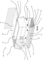
- FIGS 1A to 1C show a packaging assembly 100 for protecting an item 101, in this case a sofa (shown only in Figure 1A ), during transport of the item 101.
- the packing assembly 100 includes a rectangular planar base 102 upon which the item 101 is supported, and an inflatable cover 107.
- the base 102 includes two opposing longitudinally extending sides 103 connected at each end by two opposing (shorter) transversely extending sides 104.
- the base 102 has a length (i.e. dimension between the transverse sides 104) of about 2 m, and a width of about 1 m.
- the height of the packaging assembly is about 1 m.
- the base 102 comprises an outer sleeve 105 within which is received a rigid body (not shown) of cardboard having a hexacomb structure (a repeating hexagonal structure sandwiched between upper and lower planar layers).
- the base 102 may instead be formed of e.g. polystyrene or timber.
- the sleeve 105 comprises an opening that is closable by a fastener in the form of a zip 106. This allows the rigid body to be removed from the sleeve 105.
- the cover 107 is secured to the sleeve 105, which means the rigid body of the base 102 can be replaced (e.g. as required due to damage) without also needing to replace the cover 107.
- the inflatable cover 107 comprises opposite edge portions 108, each of which is secured to one of the longitudinal sides 103 of the base 102.
- the cover 107 also includes an intermediate portion 109 (between the edge portions) that extends over the base 102 so as to define an item-receiving cavity 110 in which the item 101 is received.
- the cover 107 extends between the edge portions 108 along an arcuate path so as to form an arch above the base 101. This results in the item-receiving cavity 110 having a semi-cylindrical shape, with two opposite semi-circular open ends 111.
- the cover 107 comprises a flexible outer skin 112 that defines a plurality of inflatable compartments 113 (only some of which are labelled for clarity). When inflated, each compartment 113 has a width of about 150 mm (i.e. the thickness of the cover 107 is about 150 mm). In use, such as during transportation and handling, these compartments 113 provide a protective barrier for the item 101 enclosed by the packaging assembly 100. To prevent piercing (and thus leakage of fluid from the compartment) the skin 112 of the cover 107 is formed of PVC.
- the cover 107 is transparent, which means that the item 101 packed in the packaging assembly 100 is visible through the cover 107 when the packaging assembly 100 is in the closed position (as shown in Figure 1A ).
- each compartment 113 is in the form of an elongate tube that is capped at both ends and that has an elliptical cross-sectional shape (as is apparent from Figure 1C ).
- the compartments 113 are parallel to one another and arranged side-by-side so as to extend in the longitudinal direction (parallel to the longitudinal sides 103 of the base 102).
- Each compartment 113 is joined to two adjacent compartments 113 by a joining portion 114 (except, of course, the two outermost compartments 113, which are each only joined to one adjacent compartment 113).
- Each joining portion 114 between two adjacent compartments 113 extends longitudinally along longitudinally extending sides of the compartments 113 (i.e. parallel to elongate axes of the compartments 113).
- each compartment 113 is joined to an adjacent compartment 113 on the major axis of the elliptical cross-section of the compartment 113 (i.e. the longer of two perpendicular axes extending through the elliptical cross-section).
- each compartment 113 is able to pivot/rotate relative to each adjacent compartment 113 to which it is joined.
- each compartment 113 can pivot about the respective joining portions 114 that join it to adjacent compartments 113.
- the cover 107 (as a whole) has flexibility (or bendability) along a transverse axis extending between the two edge portions 108 (i.e. extending in a direction across the elongate compartments 113).
- the cover 107 is more bendable (i.e. more easily bent) in this direction than in the longitudinal direction.
- This flexibility means that the shape the cover 107 (i.e. the shape of the arch) is able to conform (i.e. by flexing) to the items it covers. This allows the packaging assembly 100 to package items of various shapes while still maintaining a close fit. This close fit may help to retain the items on the base 102 (e.g. may help to restrict movement of items in transit).
- the flexibility of the cover 107 also (at least partly) facilitates the process of packing of an item in the packaging assembly 100. That is because it aids in moving the packaging assembly 100 from a closed position (as illustrated in Figure 1A ) to an open position (as illustrated in Figure 1B ).
- the cover 107 is divided into first 115 and second 116 cover portions that are releasably securable to one another.
- Each of the cover portions 115, 116 extends from a respective edge portion 108 (secured to the base 102) to a free edge 117 (i.e. being "free” in the open position) that is releasably securable to the free edge 117 of the other cover portion 115, 116.
- each free edge 117 comprises a releasable fastening arrangement 118 in the form of a hook and loop fastener that extends longitudinally along a side of the compartment 113 at the free edge 117.
- a releasable fastening arrangement 118 in the form of a hook and loop fastener that extends longitudinally along a side of the compartment 113 at the free edge 117.
- the cover 107 comprises six transverse straps 119, 120 arranged in three pairs.
- Each pair of straps 119, 120 includes a first strap 119 at the free edge 117 of the first cover portion 115 and a second strap 120 opposing the first strap 119 and provided at the free edge 117 of the second cover portion 116.
- the first 119 and second 120 straps of each pair can be engaged and tightened by way of an adjustable buckle.
- the cover 107 also includes eight end straps 121, 122 (only shown in Figure 1B ) arranged in four pairs (two pairs at each end of the packaging assembly 100).
- Each of the four pairs of end straps 121, 122 includes a first end strap 121 provided on the first cover portion 115 (so as to extend from an end of the first cover portion 115) and a second end strap 122 opposing the first end strap 121 and provided on the second cover portion 116.
- the first 121 and second 122 end straps of each pair are able to engage and be tightened by way of a buckle arrangement as described above (not shown). In this way, in the closed position, the end straps 121, 122 extend across the open semi-circular ends 111 of the item-receiving cavity 110 defined between the cover 107 and the base 102.
- Two item-securing ties 123 are secured to an upper surface of the base 102 of the packaging assembly 100. These can be secured about an item to retain the item on the base 102.
- the packaging assembly 100 is further provided with a plurality of handles 124 (shown in Figure 1A only) that facilitate handling of the packaging assembly 100.
- Two such handles 124 are provided on the cover 107, and four handles 124 are provided on the outer sleeve 105 of the base 102 (two on each of the transverse sides 104 of the base 102).
- Figures 2A and 2B illustrate a further embodiment in which the packaging assembly 100' has a cuboid, rather than semi-cylindrical, shape.
- the illustrated packaging assembly 100' includes many of the same features of the previously described embodiment, and those have been given the same reference numerals.
- the packaging assembly 100' includes a rectangular planar base 102 including an outer sleeve 105. Also provided is a cover 107 that includes two edge portions 108 secured to longitudinal sides 103 of the base 102. In this case, however, these edge portions 108 define a first pair of edge portions 108 and the cover further includes a second pair of edge portions 108 secured to the opposite transverse sides 104 of the base 102.
- the cover 107 includes four cover portions 115, 116, 126, 127, each cover portion 115, 116, 126, 127 extending from a respective side 103, 104 of the base 102 to a free edge 117.
- the cover 107 includes a first pair of cover portions 115, 116 secured to the longitudinal sides 103 of the base 102, and a second pair of cover portions 126, 127 secured to the transverse sides 104 of the base 102.
- the four cover portions 115, 116, 126, 127 are able to extend outwardly from the sides of the base 102 (so as to lie in the same plane as the base 102).
- the cover portions 115, 116, 126, 127 are upstanding from the base 102 and connect to one another so as to define walls of the cuboid packaging assembly 100' (as shown in Figure 2A ).
- the second pair of cover portions 126, 127 define end walls of the cover 107 when it is in the closed position.
- the first pair of cover portions 115, 116 define side walls of the cover 107.
- a first cover portion 115 of the first pair also defines a lid 128 that covers an opening to the (cuboid shaped) item-receiving cavity 110 of the packaging assembly 100' when in the closed position.
- Each wall of the cover 107 each comprises two (vertically stacked in the closed position) inflatable compartments 113 in the form of rectangular panels.
- the lid 128 also comprises an inflatable compartment in the form of a rectangular panel. These compartments 113 provide protection to an item stored within the cuboid cavity 110 defined by the cover 107 and the base 102 in the closed position.
- the cover 107 comprises a plurality of lateral tabs 129 (shown only in Figure 2B ).
- each of the pair of second cover portions 126, 127 is provided with two lateral tabs 129 that extend along lateral edges 130 of the cover portions 126, 127.
- these lateral edges 130 extend vertically and are positioned adjacent corresponding lateral edges 131 of the first 115 and second 116 cover portions at corners of the cover 107.
- Each lateral tab 129 connects with an adjacent cover portion 115, 116 (of the first pair of cover portions 115, 116) when the cover 107 is in the closed position.
- each lateral tab 129 includes a releasably fastening arrangement in the form of a hook and loop fastener.
- end tabs 132 are also provided on each of the second pair of cover portions 126, 127 (each end tab 132 projecting from the free edge 117 of the respective cover portion 126, 127). These end tabs 132 releasably connect with an upper surface of the lid 128 when in the closed position.
- a further end tab 132 is provided on the lid 128 (projecting from a free edge 117 of the first cover portion 115) which releasably connects with an external surface of the second cover portion 116.
- the present embodiment also includes handles 124 (not all of which are labelled for clarity) and a sleeve 125 (for displaying delivery information).
Landscapes
- Engineering & Computer Science (AREA)
- Mechanical Engineering (AREA)
- Buffer Packaging (AREA)
Applications Claiming Priority (1)
| Application Number | Priority Date | Filing Date | Title |
|---|---|---|---|
| GBGB2113848.2A GB202113848D0 (en) | 2021-09-28 | 2021-09-28 | Packaging assembly |
Publications (3)
| Publication Number | Publication Date |
|---|---|
| EP4155228A1 true EP4155228A1 (fr) | 2023-03-29 |
| EP4155228B1 EP4155228B1 (fr) | 2026-03-11 |
| EP4155228C0 EP4155228C0 (fr) | 2026-03-11 |
Family
ID=78399579
Family Applications (1)
| Application Number | Title | Priority Date | Filing Date |
|---|---|---|---|
| EP22197231.8A Active EP4155228B1 (fr) | 2021-09-28 | 2022-09-22 | Ensemble d'emballage |
Country Status (2)
| Country | Link |
|---|---|
| EP (1) | EP4155228B1 (fr) |
| GB (1) | GB202113848D0 (fr) |
Citations (4)
| Publication number | Priority date | Publication date | Assignee | Title |
|---|---|---|---|---|
| US2575784A (en) * | 1949-04-15 | 1951-11-20 | Int Paper Co | Shipping container |
| US20020064319A1 (en) * | 2000-11-30 | 2002-05-30 | Mikio Tanaka | Buffer packing bag |
| US20070221530A1 (en) * | 2006-03-21 | 2007-09-27 | Jihee Lee | Packing box equipped with airbag for shock-absorbing and manufacturing method thereof |
| US7584848B2 (en) * | 2005-12-09 | 2009-09-08 | Air-Paq, Inc. | Structure of air-packing device |
-
2021
- 2021-09-28 GB GBGB2113848.2A patent/GB202113848D0/en not_active Ceased
-
2022
- 2022-09-22 EP EP22197231.8A patent/EP4155228B1/fr active Active
Patent Citations (4)
| Publication number | Priority date | Publication date | Assignee | Title |
|---|---|---|---|---|
| US2575784A (en) * | 1949-04-15 | 1951-11-20 | Int Paper Co | Shipping container |
| US20020064319A1 (en) * | 2000-11-30 | 2002-05-30 | Mikio Tanaka | Buffer packing bag |
| US7584848B2 (en) * | 2005-12-09 | 2009-09-08 | Air-Paq, Inc. | Structure of air-packing device |
| US20070221530A1 (en) * | 2006-03-21 | 2007-09-27 | Jihee Lee | Packing box equipped with airbag for shock-absorbing and manufacturing method thereof |
Also Published As
| Publication number | Publication date |
|---|---|
| EP4155228B1 (fr) | 2026-03-11 |
| EP4155228C0 (fr) | 2026-03-11 |
| GB202113848D0 (en) | 2021-11-10 |
Similar Documents
| Publication | Publication Date | Title |
|---|---|---|
| US7757854B2 (en) | Protective carrier for fragile articles | |
| US4948154A (en) | Sterile cart cover | |
| US9637296B1 (en) | Packaging for use in the shipping of articles | |
| US6513658B1 (en) | Protective package | |
| US20080083629A1 (en) | Tote bag for carrying a plurality of wine bottles | |
| CN107148301A (zh) | 盒形运输容器 | |
| US20120118766A1 (en) | Encasement Protective Apparatus | |
| US11498740B2 (en) | Packaging material, packaging bag, and packaging method | |
| US10138045B2 (en) | Encasement protective apparatus | |
| US20030234201A1 (en) | Gift bag with protective liner | |
| US20190161232A1 (en) | Packing box | |
| GB2230509A (en) | Inflatable mail bag | |
| EP4155228A1 (fr) | Ensemble d'emballage | |
| US6948618B2 (en) | Protective packaging system | |
| CN103086079A (zh) | 自动调节夹持压力的缓冲气袋 | |
| US3437198A (en) | Cushioning package | |
| EP3746368A1 (fr) | Système, boîte et sac optimisés pour emballage, expédition, stockage et affichage de produits | |
| US20250368424A1 (en) | Shipping system for storing and/or transporting temperature-sensitive materials | |
| KR200371007Y1 (ko) | 화훼용 포장상자 | |
| ES2261029B1 (es) | Contenedor de muestras para diagnostico. | |
| JP3612820B2 (ja) | 宅配運送用スノーボード包装袋 | |
| AU2022246454A1 (en) | A transport system | |
| US11161666B2 (en) | Package for consumable products | |
| JPH055139Y2 (fr) | ||
| KR970003258Y1 (ko) | 포장용 상자 |
Legal Events
| Date | Code | Title | Description |
|---|---|---|---|
| PUAI | Public reference made under article 153(3) epc to a published international application that has entered the european phase |
Free format text: ORIGINAL CODE: 0009012 |
|
| STAA | Information on the status of an ep patent application or granted ep patent |
Free format text: STATUS: THE APPLICATION HAS BEEN PUBLISHED |
|
| AK | Designated contracting states |
Kind code of ref document: A1 Designated state(s): AL AT BE BG CH CY CZ DE DK EE ES FI FR GB GR HR HU IE IS IT LI LT LU LV MC MK MT NL NO PL PT RO RS SE SI SK SM TR |
|
| STAA | Information on the status of an ep patent application or granted ep patent |
Free format text: STATUS: REQUEST FOR EXAMINATION WAS MADE |
|
| 17P | Request for examination filed |
Effective date: 20230928 |
|
| RBV | Designated contracting states (corrected) |
Designated state(s): AL AT BE BG CH CY CZ DE DK EE ES FI FR GB GR HR HU IE IS IT LI LT LU LV MC MK MT NL NO PL PT RO RS SE SI SK SM TR |
|
| GRAP | Despatch of communication of intention to grant a patent |
Free format text: ORIGINAL CODE: EPIDOSNIGR1 |
|
| STAA | Information on the status of an ep patent application or granted ep patent |
Free format text: STATUS: GRANT OF PATENT IS INTENDED |
|
| INTG | Intention to grant announced |
Effective date: 20250520 |
|
| GRAJ | Information related to disapproval of communication of intention to grant by the applicant or resumption of examination proceedings by the epo deleted |
Free format text: ORIGINAL CODE: EPIDOSDIGR1 |
|
| STAA | Information on the status of an ep patent application or granted ep patent |
Free format text: STATUS: REQUEST FOR EXAMINATION WAS MADE |
|
| GRAP | Despatch of communication of intention to grant a patent |
Free format text: ORIGINAL CODE: EPIDOSNIGR1 |
|
| STAA | Information on the status of an ep patent application or granted ep patent |
Free format text: STATUS: GRANT OF PATENT IS INTENDED |
|
| INTC | Intention to grant announced (deleted) | ||
| INTG | Intention to grant announced |
Effective date: 20251008 |
|
| GRAS | Grant fee paid |
Free format text: ORIGINAL CODE: EPIDOSNIGR3 |
|
| GRAA | (expected) grant |
Free format text: ORIGINAL CODE: 0009210 |
|
| STAA | Information on the status of an ep patent application or granted ep patent |
Free format text: STATUS: THE PATENT HAS BEEN GRANTED |
|
| AK | Designated contracting states |
Kind code of ref document: B1 Designated state(s): AL AT BE BG CH CY CZ DE DK EE ES FI FR GB GR HR HU IE IS IT LI LT LU LV MC MK MT NL NO PL PT RO RS SE SI SK SM TR |
|
| REG | Reference to a national code |
Ref country code: CH Ref legal event code: F10 Free format text: ST27 STATUS EVENT CODE: U-0-0-F10-F00 (AS PROVIDED BY THE NATIONAL OFFICE) Effective date: 20260311 Ref country code: GB Ref legal event code: FG4D |
|
| REG | Reference to a national code |
Ref country code: DE Ref legal event code: R096 Ref document number: 602022032019 Country of ref document: DE |
|
| REG | Reference to a national code |
Ref country code: IE Ref legal event code: FG4D |
|
| U01 | Request for unitary effect filed |
Effective date: 20260325 |