EP4155244A1 - Dispositif d'épandage par soufflerie et installation d'épandage de matière à épandre - Google Patents
Dispositif d'épandage par soufflerie et installation d'épandage de matière à épandre Download PDFInfo
- Publication number
- EP4155244A1 EP4155244A1 EP22190455.0A EP22190455A EP4155244A1 EP 4155244 A1 EP4155244 A1 EP 4155244A1 EP 22190455 A EP22190455 A EP 22190455A EP 4155244 A1 EP4155244 A1 EP 4155244A1
- Authority
- EP
- European Patent Office
- Prior art keywords
- fans
- grit
- wind scattering
- scattering chamber
- wind
- Prior art date
- Legal status (The legal status is an assumption and is not a legal conclusion. Google has not performed a legal analysis and makes no representation as to the accuracy of the status listed.)
- Granted
Links
Images


Classifications
-
- B—PERFORMING OPERATIONS; TRANSPORTING
- B27—WORKING OR PRESERVING WOOD OR SIMILAR MATERIAL; NAILING OR STAPLING MACHINES IN GENERAL
- B27N—MANUFACTURE BY DRY PROCESSES OF ARTICLES, WITH OR WITHOUT ORGANIC BINDING AGENTS, MADE FROM PARTICLES OR FIBRES CONSISTING OF WOOD OR OTHER LIGNOCELLULOSIC OR LIKE ORGANIC MATERIAL
- B27N3/00—Manufacture of substantially flat articles, e.g. boards, from particles or fibres
- B27N3/08—Moulding or pressing
- B27N3/10—Moulding of mats
- B27N3/14—Distributing or orienting the particles or fibres
-
- B—PERFORMING OPERATIONS; TRANSPORTING
- B65—CONVEYING; PACKING; STORING; HANDLING THIN OR FILAMENTARY MATERIAL
- B65G—TRANSPORT OR STORAGE DEVICES, e.g. CONVEYORS FOR LOADING OR TIPPING, SHOP CONVEYOR SYSTEMS OR PNEUMATIC TUBE CONVEYORS
- B65G53/00—Conveying materials in bulk through troughs, pipes or tubes by floating the materials or by flow of gas, liquid or foam
- B65G53/04—Conveying materials in bulk pneumatically through pipes or tubes; Air slides
- B65G53/06—Gas pressure systems operating without fluidisation of the materials
- B65G53/10—Gas pressure systems operating without fluidisation of the materials with pneumatic injection of the materials by the propelling gas
-
- B—PERFORMING OPERATIONS; TRANSPORTING
- B27—WORKING OR PRESERVING WOOD OR SIMILAR MATERIAL; NAILING OR STAPLING MACHINES IN GENERAL
- B27N—MANUFACTURE BY DRY PROCESSES OF ARTICLES, WITH OR WITHOUT ORGANIC BINDING AGENTS, MADE FROM PARTICLES OR FIBRES CONSISTING OF WOOD OR OTHER LIGNOCELLULOSIC OR LIKE ORGANIC MATERIAL
- B27N3/00—Manufacture of substantially flat articles, e.g. boards, from particles or fibres
- B27N3/02—Manufacture of substantially flat articles, e.g. boards, from particles or fibres from particles
-
- B—PERFORMING OPERATIONS; TRANSPORTING
- B27—WORKING OR PRESERVING WOOD OR SIMILAR MATERIAL; NAILING OR STAPLING MACHINES IN GENERAL
- B27N—MANUFACTURE BY DRY PROCESSES OF ARTICLES, WITH OR WITHOUT ORGANIC BINDING AGENTS, MADE FROM PARTICLES OR FIBRES CONSISTING OF WOOD OR OTHER LIGNOCELLULOSIC OR LIKE ORGANIC MATERIAL
- B27N3/00—Manufacture of substantially flat articles, e.g. boards, from particles or fibres
- B27N3/04—Manufacture of substantially flat articles, e.g. boards, from particles or fibres from fibres
Definitions
- the invention relates to a wind scattering device for scattering grit or for scattering grit on a grit conveyor, with at least one wind scattering chamber which has an upper grit opening through which grit is introduced into the wind scattering chamber and with a plurality of fans for generating at least one air flow for the separation of the grit in the wind scattering chamber, the air flow generated by the fans entering the wind scattering chamber via an inflow opening which defines an inflow surface, the inflow surface extending along the height of the wind scattering chamber and being oriented, for example, vertically or substantially vertically.
- Such a (wind) scattering device is usually integrated into a grit system for the production of grit mats for the production of material panels, in particular wood-based panels.
- Wood-based panels mean in particular chipboard made from wood chips or alternatively fiberboard made from wood fibers. In principle, however, other material panels are also covered by the invention.
- the grit mats scattered onto the grit conveyor e.g. scattering belt conveyor
- the grit mats scattered onto the grit conveyor are pressed in a press, for example a continuously operating press or a cycle press, using pressure and/or heat to form material panels, e.g. wood-based panels.
- the quality of the panels produced, eg wood-based panels depends to a large extent on the quality or the properties of the mats of grit produced with the aid of the scattering device.
- the grit is usually glued to the grit, eg glued shavings or alternatively glued fibers, which can be fed to the scattering device from a
- a grit system can have several scattering devices, which are also referred to as scattering heads, e.g. if multi-layer grit mats of (two) top layers (e.g. made of fine material) and e.g. a middle layer (e.g. made of coarse material) are to be produced.
- the individual scattering devices are arranged one behind the other along the conveying direction of the spreading belt conveyor, so that first a first cover layer is spread onto the spreading belt conveyor, then one or more middle layers are spread onto this first covering layer and then a second covering layer is spread onto the middle layer or the middle classes.
- the wind scattering device according to the invention can be used, for example, to produce covering layers within such a grit system.
- the air flow generated in the wind scattering chamber separates the chips in the wind scattering chamber, with coarser chips falling near the inflow surface and finer chips falling in the rear area, i.e. in the area of the wind scattering chamber facing away from the inflow surface.
- layers e.g. cover layers
- One or more screens can optionally be arranged in the wind scattering chamber in order to optimize the separation.
- wind scattering devices of the type described above are used, in which the flow or air flow required for the air separation is generated by a common air generation system with one or more powerful fans.
- the flow generated by the fan(s) is directed into an antechamber, in which dynamic pressure is generated.
- dynamic pressure is generated from this dynamic pressure chamber.
- individual discharge pipes lead the flow into the actual wind scattering chamber.
- the drainage pipes can be regulated by apertures in their respective amount. This makes it possible to generate a distribution of the wind speeds that is as homogeneous as possible over the entire cross section of the wind scattering chamber.
- Such a wind scattering device is, for example, in DE 10 2015 112 013 A1 described.
- a nozzle unit In the area of the inflow surface into the wind scattering chamber, a nozzle unit is provided which has a large number of outlet nozzles arranged in columns and rows, with the outlet nozzles tapering in the direction of flow in a funnel shape from a rectangular inlet cross section to a round or oval outlet cross section.
- the nozzle unit can be followed by a register unit in the direction of flow, which has several register strips next to one another, which each have several openings assigned to the outlet nozzles distributed over the height and are height-adjustable for setting variable outlet cross sections of the nozzle unit.
- a few large-sized fans are provided, each generating vertically oriented air flows, the air supply housing being designed as a deflection housing with at least one vertical housing section, one horizontal housing section and a deflection section arranged in between.
- At least four fans can be provided, of which two fans are assigned to an upper area of the nozzle unit and two fans to a lower area of the nozzle unit--each with the interposition of a deflection path.
- a forming station for the production of Grit mats described in the course of the production of wood-based panels in which the scatter particles are transported to a discharge point via a conveyor belt and in the path of the scatter particles from this discharge point to the grit conveyor on which the mat is produced, either one or more vibrating frames or one or more Special throwing rollers or one or more whirlwind nozzles or a combination of these aggregates are provided, over or past which the scattering particles coming from the throwing point have to pass in substantially different directions for orientation.
- Wind nozzles can be provided to generate an air turbulence.
- the invention is based on the object of creating a wind scattering device and a grit system with such a wind scattering device with which grit mats of high quality can be produced in an economical manner and which is also characterized by a compact and economical structure.
- the invention teaches that the fans are arranged in a fan field and consequently form a fan field, which comprises several fans distributed over the height of the fan field and over the width of the fan field, which are parallel to one another generate oriented individual streams or individual air streams, the fan array being connected to the wind scattering chamber in such a way that the individual streams of the fans are oriented perpendicularly or essentially perpendicularly to the inflow surface of the wind scattering chamber.
- the fans of the fan array preferably all of the fans of the fan array, are arranged, for example, in a common fan plane, with this fan plane being perpendicular to the plane generated by the fans Individual flows is oriented and this fan plane is preferably oriented parallel or substantially parallel to the inflow surface of the wind scattering chamber. Consequently, a large number of individual fans are provided, which together form a fan field, with the individual fans each generating individual flows which together form the air flow within the wind scattering chamber.
- the fans are preferably positioned in such a way that the flow direction of the individual flows generated by the fans is parallel or essentially parallel to the inflow direction of the air flow entering the wind scattering chamber at the inflow surface. The individual flows generated by the fans consequently enter the inflow surface or the wind scattering chamber without direction deflection.
- the invention is based on the finding that a wind spreading device with a compact structure and excellent flow conditions can be designed very economically if the air flow is not generated with a few high-performance fans, but if a fan field with a large number of fans is used, which can each have a relatively small power and are therefore characterized by a particularly compact structure.
- the fans are no longer oriented in such a way that they generate vertical air currents, which are directed into the area of the inflow surface via a deflection chamber, but the fan field immediately generates a large number of individual currents with the individual fans, which are already in the direction of the air entering the wind scattering chamber Airflow are oriented, so that there is no direction deflection.
- the storage chamber used in the prior art can be omitted. The air is sucked in directly by the fans and pressed into the wind scattering chamber via the inflow surface without having to go from the generation of the individual streams to entering the inflow surface Wind scattering chamber a direction deflection of the air flow is required.
- the fan field has several, e.g. at least three, preferably at least four, fans distributed over the height and/or several, e.g. at least three, preferably at least four, fans distributed over the width, so that e.g. four fans over the height and six fans over the width can be distributed.
- the fan field has, for example, at least nine fans, preferably at least twelve fans, particularly preferably at least sixteen fans, for example twenty-four fans or more.
- the fans can be arranged in a checkerboard pattern and consequently in rows and columns. However, there is also the option of arranging the individual fans offset in relation to one another in terms of height and width. It is always useful if the fans are arranged in a common plane. Alternatively, however, the fans can also be arranged offset to one another in relation to the direction of flow forwards and backwards.
- the fan field particularly preferably extends over the entire height and/or over the entire width of the inflow surface.
- This inflow surface can be formed, for example, by an inflow opening in the wind scattering chamber or in the housing of the wind scattering chamber, with this opening having a predetermined height and a predetermined width.
- the height and width of the fan field preferably correspond essentially to the height and width of such a rectangular inflow opening, which can be arranged, for example, in a vertically or approximately vertically oriented housing wall of the wind scattering chamber.
- a major advantage of the embodiment of the invention is that not with a few high-performance fans large air flows are generated, but that a large number of inexpensive individual fans with relatively low power can be used, which are not only characterized by low acquisition and operating costs, but also by a compact design.
- individual fans can be used which have a maximum volume flow or a maximum delivery volume of up to 3000 m 3 /h, for example a maximum of 2000 m 3 /h, particularly preferably a maximum of 1500 m 3 /h.
- the individual fans or their fan housing can be dimensioned relatively small and have, for example, a housing width and/or a housing height of at most 400 mm, for example at most 300 mm.
- the depth of the fans or the fan housing along the direction of flow can be, for example, a maximum of 400 mm, preferably a maximum of 300 mm.
- the fans are preferably designed as axial fans, the axes of rotation of which are oriented perpendicular to the inflow surface of the wind scattering chamber and/or perpendicular to the grit flow of the grit entering the grit chamber.
- a diffuser unit which has a multiplicity of diffusers which are arranged in columns and rows, for example.
- the individual diffusers are each designed with a round or oval inlet cross-section and a rectangular outlet cross-section, with the fans being connected to the round or oval inlet cross-section and the outlet cross-sections of the diffusers forming a flat (uniform) diffuser exit surface that is parallel or essentially parallel is oriented to the inflow surface of the wind scattering chamber or forms this inflow surface. Consequently, such a diffuser unit is preferably connected to the fan field.
- fans e.g as axial fans, usually initially generate a flow with a round cross-section.
- the diffuser unit can distribute the individual flows over rectangular cross sections and thus over an overall uniform inflow area.
- the fans are preferably connected directly to the diffuser unit and without flow deflection, or alternatively they can also be integrated directly into the diffuser unit.
- a flow straightener can be arranged downstream of the fan field or the optionally provided diffuser unit, which generates a homogeneous air flow entering the wind scattering chamber.
- This flow straightener can be connected directly to the inflow opening of the wind scattering chamber, for example, so that the flow straightener forms the inflow surface of the wind scattering chamber or can be oriented parallel to the inflow surface of the wind scattering chamber.
- the flow straightener can be designed as a perforated plate or as a duct plate with a large number of individual ducts, the individual ducts having a smaller and preferably significantly smaller cross-section than the diameter of the fans and/or the diameter of the diffusers.
- the individual fans within the field of fans can be controlled individually, for example as a function of measured values that represent, for example, a scattering distribution of the grit on the scattering belt conveyor. It is consequently possible to analyze or monitor the scattering result with one or more measuring devices and to adapt the flow conditions depending on this scattering result by selectively controlling individual fans or also all fans of the fan array.
- the individual streams generated by the fans can preferably each be individually adjustable, for example by varying the speed of the rotating fan elements and/or by varying the speed of the drives driving the fan elements, eg electric motors.
- the fans or the speed of the fans or the speed of the drives can be controlled or regulated individually, preferably via a common control or regulating device for the fan field.
- a large number of individually speed-controlled drives are preferably provided so that the flow conditions in the area of the inflow opening can be varied in a targeted manner, also because the individual flows generated by the fans enter the wind scattering chamber essentially directly in the area of the inflow surface without direction deflection.
- the invention also relates to a grit system with a scattering device of the type described.
- the grit system consequently has at least the scattering device and a grit conveyor, eg a belt conveyor, arranged below the scattering device.
- the grit is sprinkled, for example, via an upper grit opening into the wind scattering chamber, with a grit bunker preferably being provided above this wind scattering chamber, with which the grit is supplied.
- other feed devices such as conveyor belts, screw conveyors or the like can also be provided in the area of the upper spreading material opening.
- the grit system has in the area of Spreader belt conveyor preferably has a measuring device for determining or monitoring the spread distribution of the spreading material on the spreader belt conveyor.
- the grit system can have a control or regulating device with which the fan field can be controlled or regulated, e.g. depending on measured values that are recorded with the measuring device, wherein - as described - preferably the individual fans of the fan field can be controlled or regulated individually.
- the critical wavelength of a disturbance in the generated mat in the transverse direction can be compensated for by the controllability and consequently feedback.
- In 1 shows a grit system for the production of grit mats for the production of wood-based panels, such as chipboard or fiberboard.
- This grit system has a grit bunker 1, which is designed as a dosing bunker and delivers the grit to a scattering device 3, for example via scattering rollers or metering rollers 2. With the scattering device 3, the grit is scattered on the scatter belt conveyor 4, on which a grit mat is formed, which is then in a press using Pressure and heat to form a wood-based panel, such as chipboard or fiberboard is pressed.
- Such a grit installation usually has a number of scattering devices for producing multi-layer grit mats or grit mats with a number of layers, with cover layers and one or more middle layers being spread, for example.
- a scattering device 3 for producing a layer for example a covering layer of relatively fine chips, is shown as an example.
- This scattering device 3 is designed as a wind scattering device. It has a wind scattering chamber 5, which has an upper grit opening 6, through which the grit enters the wind scattering chamber 5, for example from the grit bunker 1, specifically from top to bottom in the exemplary embodiment.
- the spreading device 3 has several fans 7 for generating an air flow L for separating the spreading material in the wind spreading chamber 5 .
- the wind scattering chamber 5 has an inflow opening 12 which forms a vertical or essentially vertical inflow surface F through which the air flow L generated by the fans 7 enters the wind scattering chamber 5 .
- the inflow surface F consequently extends in the vertical direction or along the height of the wind scattering chamber, ie, for example in the vertical direction.
- the air flow L which in the exemplary embodiment enters the wind scattering chamber 5 in a substantially horizontal direction via the inflow opening 12 and consequently through the inflow surface F, separates the particles, e.g. chips, with coarser particles entering the area of the wind scattering chamber facing the inflow opening 12 fall down and finer chips get into the rear region of the wind scattering chamber 5 facing away from the inflow surface 12 and fall down there.
- sieves 9 for example flying chip sieves
- sieves 9 can optionally be arranged in the wind scattering chamber 5, which are arranged transversely to the direction of flow and can be equipped with fans, for example to ensure optimal chip distribution and precise granulometric separation.
- a roller screen 10 be provided with discharge screw 11.
- a vibrating screen can also be provided instead of the roller screen. Clumps of glue, for example, can be retained via the roller screen 10 or a corresponding vibrating screen, which can then be discharged with a discharge screw 11 .
- the antechambers or dynamic pressure chambers provided in the prior art between the fans and the entry into the wind scattering chamber are dispensed with.
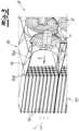
- the fans 7 are arranged according to the invention in a fan field 8, which comprises several fans 7 distributed over the height and width, which generate individual streams E oriented parallel to one another, namely in the horizontal direction in the exemplary embodiment.
- the fan field 8 is consequently connected to the wind scattering chamber 5 in such a way that the individual streams E of the fans 7 are oriented perpendicularly or essentially perpendicularly to the inflow surface F of the wind scattering chamber 5 .
- a very compact fan field 8 is realized, which is oriented overall transversely and consequently preferably perpendicular to the orientation of the air flow L, which is blown into the wind scattering chamber 5 via the inflow surface F.
- all the fans 7 of the fan field 8 are arranged in a common fan plane V, which is oriented parallel or essentially parallel to the inflow surface of the wind scattering chamber 5 . This results in the fans 7 being positioned in such a way that the flow direction of the individual flows E generated by the fans is parallel to the inflow direction of the air flow L entering the wind scattering chamber 5 at the inflow surface F.
- the individual streams E generated by the fans 7 consequently enter the wind scattering chamber 5 without a direction deflection.
- the fan field 8 is provided according to the invention, in which at least three fans 7 over are distributed over the height and at least three fans 7 are distributed over the width.
- a 4 ⁇ 6 arrangement is implemented, ie four fans 7 are distributed over the height and six fans 7 are distributed over the width, so that the fan field 8 is composed of twenty-four fans 7 in the exemplary embodiment. It is particularly advantageous if the fan field 8 extends over the entire height and the entire width of the inflow surface F, i.e.
- the fan field is arranged (matrix-like) over the entire inflow surface or inflow opening of the wind scattering chamber, so that in a very compact structure a large-area air flow L is generated and enters directly into the chamber 5 without a dynamic pressure chamber and/or directional deflections for the air flow being provided between the fans 7 and the inlet opening 12 .
- a diffuser unit 13 is additionally provided between the fan field 8 and the inlet opening 12, which diffuser unit has a multiplicity of diffusers 14 arranged in columns and rows.
- Each diffuser 14 has a round inlet cross section 14a and a rectangular outlet cross section 14b.
- the fans 7 are each connected to the round inlet cross-sections 14a, so that the individual streams E enter the diffuser 14 via the round inlet cross-sections 14a and exit via the rectangular outlet cross-section 14b, so that an essentially uniform, flat diffuser outlet surface is formed via the outlet cross-sections 14b , which is oriented parallel or essentially parallel to the inflow surface F of the wind scattering chamber 5 .
- the fans 7 are connected to this diffuser unit 13 directly and without flow deflection.
- the diffuser unit 13 and consequently also the fan field 8 can also have a flow straightener 15 for generating a homogeneous air flow entering the wind scattering chamber Be downstream of the air flow L, which forms the inflow surface F of the wind scattering chamber 5 or can also be oriented parallel to the inflow surface F of the wind scattering chamber 5 .
- this flow straightener 15 has a multiplicity of small flow channels 16 , a multiplicity of straightening channels 16 being arranged over the surface of a fan 7 and consequently also over a single outlet surface 14b of the diffuser 14 . The flow generated by the fans 7 is thus balanced, so that a laminarly directed air flow is produced, which enters the chamber 5 as an air flow L.
- the fan field 8 that is essential to the invention has a very compact design, because the individual fans 7 can be designed to be very compact and with relatively low power for generating or conveying a relatively low volume flow.
- fans with a nominal diameter D of about 100 mm to 400 mm, for example 200 mm to 300 mm and about 250 mm in the exemplary embodiment can be used.
- Each individual fan 7 can generate a relatively low (maximum) volume flow of, for example, less than 2000 m 3 /h, preferably less than 1500 m 3 /h, and can also only be designed for such volume flows.
- Each individual fan 7 can have a height h and width b of less than 300 mm, so that the fan field can be formed very compactly from a large number of fans. Due to the small overall depth t of the individual fans of, for example, less than 400 mm, preferably less than 300 mm, there is also a fan field with a very small depth and consequently thickness. Since no additional dynamic pressure chamber and no other components have to be provided on the back of the fans, a very compact design and at the same time a homogeneous air flow is guaranteed.
- the individual fans 7 are preferably designed as axial fans.
- the axes of rotation X of the axial fans 7 are oriented perpendicularly to the inflow surface F of the wind scattering chamber 5 .
- the axes of rotation X of the fans 7 are also oriented vertically or essentially vertically in relation to the flow of grit entering the wind scattering chamber 5, which flow is directed from top to bottom.
- the figures show that a very compact structure is realized. There is no voluminous dynamic pressure chamber. The air is sucked in directly by the fans 7 and pressed into the chamber 5.
- the individual fans 7 within the fan field 8 can preferably be controlled individually. It is possible, for example, to variably set the conveying capacity or the volume flow by controlling or regulating the speed of the fans 7, specifically for each individual fan 7 separately. In this way, there is the possibility of making the flow conditions over the inflow area F variable.
- the control can preferably take place as a function of measured values which represent, for example, a scattering distribution of the grit on the grit conveyor 4 .
- a measuring device 17 can be provided in the area of the spreading belt conveyor, with which the scattering distribution of the grit on the grit conveyor 4 can be analyzed, eg a thickness measuring device, with which the thickness of the grit mat can be analyzed across the width.
- the distribution of the individual streams E can be manipulated with the aid of a control or regulating device 18 in that the fans 7 are controlled in a targeted manner, for example via the speed of the drives for the fans.
- a control or regulating device 18 can be connected both to the measuring device 17 and to the fans 7 or their drives.
- the fan field 8 according to the invention is composed of a large number of individual fans 7, which are characterized by a compact design.
- Such compact axial fans 7 are used in industry in a wide variety of areas, so that known components can be used that are available at low cost.
Landscapes
- Engineering & Computer Science (AREA)
- Life Sciences & Earth Sciences (AREA)
- Mechanical Engineering (AREA)
- Manufacturing & Machinery (AREA)
- Wood Science & Technology (AREA)
- Forests & Forestry (AREA)
- Structures Of Non-Positive Displacement Pumps (AREA)
Applications Claiming Priority (1)
| Application Number | Priority Date | Filing Date | Title |
|---|---|---|---|
| DE102021124789.6A DE102021124789B3 (de) | 2021-09-24 | 2021-09-24 | Windstreuvorrichtung und Streugutanlage |
Publications (3)
| Publication Number | Publication Date |
|---|---|
| EP4155244A1 true EP4155244A1 (fr) | 2023-03-29 |
| EP4155244B1 EP4155244B1 (fr) | 2024-07-17 |
| EP4155244C0 EP4155244C0 (fr) | 2024-07-17 |
Family
ID=82939911
Family Applications (1)
| Application Number | Title | Priority Date | Filing Date |
|---|---|---|---|
| EP22190455.0A Active EP4155244B1 (fr) | 2021-09-24 | 2022-08-16 | Dispositif d'épandage par soufflerie et installation d'épandage de matière à épandre |
Country Status (3)
| Country | Link |
|---|---|
| EP (1) | EP4155244B1 (fr) |
| CN (1) | CN115849013A (fr) |
| DE (1) | DE102021124789B3 (fr) |
Cited By (2)
| Publication number | Priority date | Publication date | Assignee | Title |
|---|---|---|---|---|
| EP4603407A1 (fr) | 2024-02-19 | 2025-08-20 | Sika Technology AG | Récipient pour matériau visqueux et dispositif pour transporter un matériau visqueux comprenant un tel récipient |
| EP4603408A1 (fr) | 2024-02-19 | 2025-08-20 | Sika Technology AG | Récipient pour matériau visqueux et dispositif pour transporter un matériau visqueux comprenant un tel récipient |
Families Citing this family (1)
| Publication number | Priority date | Publication date | Assignee | Title |
|---|---|---|---|---|
| DE102024002581A1 (de) | 2024-08-08 | 2026-02-12 | Siempelkamp Maschinen- Und Anlagenbau Gmbh | Verfahren zur Herstellung einer Streugutmatte sowie Vorrichtung zur Durchführung des Verfahrens und Werkstoffplatte |
Citations (3)
| Publication number | Priority date | Publication date | Assignee | Title |
|---|---|---|---|---|
| DE1065164B (fr) * | 1957-10-09 | 1959-09-10 | ||
| DE1205274B (de) | 1961-03-01 | 1965-11-18 | Schenck Gmbh Carl | Vorrichtung zur Herstellung von Formkoerpern, insbesondere aus Holzspaenen |
| DE102015112013A1 (de) | 2015-07-23 | 2017-01-26 | Siempelkamp Maschinen- Und Anlagenbau Gmbh | Windstreuvorrichtung |
Family Cites Families (3)
| Publication number | Priority date | Publication date | Assignee | Title |
|---|---|---|---|---|
| CN105890145A (zh) * | 2016-06-03 | 2016-08-24 | 北京中矿博能节能科技有限公司 | 煤矿送风机组及使用该送风机组的井口空气加热机组 |
| DE102020005686B4 (de) | 2020-09-17 | 2022-05-05 | Siempelkamp Maschinen- Und Anlagenbau Gmbh | Windstreuvorrichtung |
| DE102020005687B4 (de) | 2020-09-17 | 2022-03-24 | Siempelkamp Maschinen- Und Anlagenbau Gmbh | Windstreuvorrichtung |
-
2021
- 2021-09-24 DE DE102021124789.6A patent/DE102021124789B3/de active Active
-
2022
- 2022-08-16 EP EP22190455.0A patent/EP4155244B1/fr active Active
- 2022-09-23 CN CN202211163395.8A patent/CN115849013A/zh active Pending
Patent Citations (3)
| Publication number | Priority date | Publication date | Assignee | Title |
|---|---|---|---|---|
| DE1065164B (fr) * | 1957-10-09 | 1959-09-10 | ||
| DE1205274B (de) | 1961-03-01 | 1965-11-18 | Schenck Gmbh Carl | Vorrichtung zur Herstellung von Formkoerpern, insbesondere aus Holzspaenen |
| DE102015112013A1 (de) | 2015-07-23 | 2017-01-26 | Siempelkamp Maschinen- Und Anlagenbau Gmbh | Windstreuvorrichtung |
Cited By (2)
| Publication number | Priority date | Publication date | Assignee | Title |
|---|---|---|---|---|
| EP4603407A1 (fr) | 2024-02-19 | 2025-08-20 | Sika Technology AG | Récipient pour matériau visqueux et dispositif pour transporter un matériau visqueux comprenant un tel récipient |
| EP4603408A1 (fr) | 2024-02-19 | 2025-08-20 | Sika Technology AG | Récipient pour matériau visqueux et dispositif pour transporter un matériau visqueux comprenant un tel récipient |
Also Published As
| Publication number | Publication date |
|---|---|
| EP4155244B1 (fr) | 2024-07-17 |
| EP4155244C0 (fr) | 2024-07-17 |
| CN115849013A (zh) | 2023-03-28 |
| DE102021124789B3 (de) | 2022-10-13 |
Similar Documents
| Publication | Publication Date | Title |
|---|---|---|
| EP4155244B1 (fr) | Dispositif d'épandage par soufflerie et installation d'épandage de matière à épandre | |
| EP3130436B1 (fr) | Dispositif de soufflerie | |
| EP0800901B1 (fr) | Procédé et appareil pour fabriquer un mat | |
| DE3507764C2 (fr) | ||
| DE19835419A1 (de) | Vorrichtung und Verfahren zur Windsichtung | |
| WO2018011430A1 (fr) | Système de dispersion et procédés de fabrication d'un mat de matière dispersée au cours de la fabrication de panneaux de matériau | |
| DE102020005687B4 (de) | Windstreuvorrichtung | |
| DE19846106A1 (de) | Streustation | |
| EP1442855B1 (fr) | Dispositif pour distribution des matériaux granulaires sur un support en mouvement continu | |
| DE4326148B4 (de) | Einrichtung zur Streuung von Fasern, insbesondere von Spänen | |
| EP2504135B1 (fr) | Installation et procédé de formage d'une nappe de matériau de dispersion sur une bande de formage lors de la fabrication de plaques de matériau | |
| DE102020005686B4 (de) | Windstreuvorrichtung | |
| DE102024003636B3 (de) | Windstreuvorrichtung und Verfahren zum Streuen | |
| DE102016117383B4 (de) | Sichter | |
| EP3970867B1 (fr) | Dispositif d'épandage au moyen du vent | |
| DE102006030122A1 (de) | Streugutanlage | |
| EP2347874B1 (fr) | Procédé et dispositif de mélange d'un mélange de particules avec une colle | |
| EP3976333A1 (fr) | Dispositif et procédé de fabrication d'un non-tissé | |
| EP4100223A1 (fr) | Chambre de dispersion par soufflage pour disperser et façonner un matériau apte à l'écoulement sur une bande de formage | |
| EP3976334B1 (fr) | Dispositif et procédé de fabrication d'une nappe de fibres | |
| DE102007056109A1 (de) | Vorrichtung zur Windsichtung von Streugut im Zuge der Streuung einer Pressgutmatte oder einer Schicht derselben | |
| DE102024002581A1 (de) | Verfahren zur Herstellung einer Streugutmatte sowie Vorrichtung zur Durchführung des Verfahrens und Werkstoffplatte | |
| DE2211879C2 (de) | Verfahren und Vorrichtung zum Konditionieren von Tabak | |
| DE2325508A1 (de) | Vorrichtung zum herstellen von plattenfoermigen werkstuecken | |
| DE102017110600B4 (de) | Sichter |
Legal Events
| Date | Code | Title | Description |
|---|---|---|---|
| PUAI | Public reference made under article 153(3) epc to a published international application that has entered the european phase |
Free format text: ORIGINAL CODE: 0009012 |
|
| STAA | Information on the status of an ep patent application or granted ep patent |
Free format text: STATUS: THE APPLICATION HAS BEEN PUBLISHED |
|
| STAA | Information on the status of an ep patent application or granted ep patent |
Free format text: STATUS: REQUEST FOR EXAMINATION WAS MADE |
|
| AK | Designated contracting states |
Kind code of ref document: A1 Designated state(s): AL AT BE BG CH CY CZ DE DK EE ES FI FR GB GR HR HU IE IS IT LI LT LU LV MC MK MT NL NO PL PT RO RS SE SI SK SM TR |
|
| 17P | Request for examination filed |
Effective date: 20230303 |
|
| RBV | Designated contracting states (corrected) |
Designated state(s): AL AT BE BG CH CY CZ DE DK EE ES FI FR GB GR HR HU IE IS IT LI LT LU LV MC MK MT NL NO PL PT RO RS SE SI SK SM TR |
|
| GRAP | Despatch of communication of intention to grant a patent |
Free format text: ORIGINAL CODE: EPIDOSNIGR1 |
|
| STAA | Information on the status of an ep patent application or granted ep patent |
Free format text: STATUS: GRANT OF PATENT IS INTENDED |
|
| GRAJ | Information related to disapproval of communication of intention to grant by the applicant or resumption of examination proceedings by the epo deleted |
Free format text: ORIGINAL CODE: EPIDOSDIGR1 |
|
| STAA | Information on the status of an ep patent application or granted ep patent |
Free format text: STATUS: REQUEST FOR EXAMINATION WAS MADE |
|
| INTG | Intention to grant announced |
Effective date: 20240124 |
|
| INTC | Intention to grant announced (deleted) | ||
| GRAP | Despatch of communication of intention to grant a patent |
Free format text: ORIGINAL CODE: EPIDOSNIGR1 |
|
| STAA | Information on the status of an ep patent application or granted ep patent |
Free format text: STATUS: GRANT OF PATENT IS INTENDED |
|
| GRAS | Grant fee paid |
Free format text: ORIGINAL CODE: EPIDOSNIGR3 |
|
| INTG | Intention to grant announced |
Effective date: 20240314 |
|
| GRAA | (expected) grant |
Free format text: ORIGINAL CODE: 0009210 |
|
| STAA | Information on the status of an ep patent application or granted ep patent |
Free format text: STATUS: THE PATENT HAS BEEN GRANTED |
|
| AK | Designated contracting states |
Kind code of ref document: B1 Designated state(s): AL AT BE BG CH CY CZ DE DK EE ES FI FR GB GR HR HU IE IS IT LI LT LU LV MC MK MT NL NO PL PT RO RS SE SI SK SM TR |
|
| REG | Reference to a national code |
Ref country code: CH Ref legal event code: EP |
|
| REG | Reference to a national code |
Ref country code: DE Ref legal event code: R096 Ref document number: 502022001246 Country of ref document: DE |
|
| REG | Reference to a national code |
Ref country code: IE Ref legal event code: FG4D Free format text: LANGUAGE OF EP DOCUMENT: GERMAN |
|
| U01 | Request for unitary effect filed |
Effective date: 20240730 |
|
| U07 | Unitary effect registered |
Designated state(s): AT BE BG DE DK EE FI FR IT LT LU LV MT NL PT SE SI Effective date: 20240816 |
|
| U20 | Renewal fee for the european patent with unitary effect paid |
Year of fee payment: 3 Effective date: 20240820 |
|
| PG25 | Lapsed in a contracting state [announced via postgrant information from national office to epo] |
Ref country code: NO Free format text: LAPSE BECAUSE OF FAILURE TO SUBMIT A TRANSLATION OF THE DESCRIPTION OR TO PAY THE FEE WITHIN THE PRESCRIBED TIME-LIMIT Effective date: 20241017 |
|
| PG25 | Lapsed in a contracting state [announced via postgrant information from national office to epo] |
Ref country code: GR Free format text: LAPSE BECAUSE OF FAILURE TO SUBMIT A TRANSLATION OF THE DESCRIPTION OR TO PAY THE FEE WITHIN THE PRESCRIBED TIME-LIMIT Effective date: 20241018 Ref country code: PL Free format text: LAPSE BECAUSE OF FAILURE TO SUBMIT A TRANSLATION OF THE DESCRIPTION OR TO PAY THE FEE WITHIN THE PRESCRIBED TIME-LIMIT Effective date: 20240717 |
|
| PG25 | Lapsed in a contracting state [announced via postgrant information from national office to epo] |
Ref country code: IS Free format text: LAPSE BECAUSE OF FAILURE TO SUBMIT A TRANSLATION OF THE DESCRIPTION OR TO PAY THE FEE WITHIN THE PRESCRIBED TIME-LIMIT Effective date: 20241117 |
|
| PG25 | Lapsed in a contracting state [announced via postgrant information from national office to epo] |
Ref country code: HR Free format text: LAPSE BECAUSE OF FAILURE TO SUBMIT A TRANSLATION OF THE DESCRIPTION OR TO PAY THE FEE WITHIN THE PRESCRIBED TIME-LIMIT Effective date: 20240717 |
|
| PG25 | Lapsed in a contracting state [announced via postgrant information from national office to epo] |
Ref country code: ES Free format text: LAPSE BECAUSE OF FAILURE TO SUBMIT A TRANSLATION OF THE DESCRIPTION OR TO PAY THE FEE WITHIN THE PRESCRIBED TIME-LIMIT Effective date: 20240717 Ref country code: RS Free format text: LAPSE BECAUSE OF FAILURE TO SUBMIT A TRANSLATION OF THE DESCRIPTION OR TO PAY THE FEE WITHIN THE PRESCRIBED TIME-LIMIT Effective date: 20241017 |
|
| PG25 | Lapsed in a contracting state [announced via postgrant information from national office to epo] |
Ref country code: RS Free format text: LAPSE BECAUSE OF FAILURE TO SUBMIT A TRANSLATION OF THE DESCRIPTION OR TO PAY THE FEE WITHIN THE PRESCRIBED TIME-LIMIT Effective date: 20241017 Ref country code: PL Free format text: LAPSE BECAUSE OF FAILURE TO SUBMIT A TRANSLATION OF THE DESCRIPTION OR TO PAY THE FEE WITHIN THE PRESCRIBED TIME-LIMIT Effective date: 20240717 Ref country code: NO Free format text: LAPSE BECAUSE OF FAILURE TO SUBMIT A TRANSLATION OF THE DESCRIPTION OR TO PAY THE FEE WITHIN THE PRESCRIBED TIME-LIMIT Effective date: 20241017 Ref country code: IS Free format text: LAPSE BECAUSE OF FAILURE TO SUBMIT A TRANSLATION OF THE DESCRIPTION OR TO PAY THE FEE WITHIN THE PRESCRIBED TIME-LIMIT Effective date: 20241117 Ref country code: HR Free format text: LAPSE BECAUSE OF FAILURE TO SUBMIT A TRANSLATION OF THE DESCRIPTION OR TO PAY THE FEE WITHIN THE PRESCRIBED TIME-LIMIT Effective date: 20240717 Ref country code: GR Free format text: LAPSE BECAUSE OF FAILURE TO SUBMIT A TRANSLATION OF THE DESCRIPTION OR TO PAY THE FEE WITHIN THE PRESCRIBED TIME-LIMIT Effective date: 20241018 Ref country code: ES Free format text: LAPSE BECAUSE OF FAILURE TO SUBMIT A TRANSLATION OF THE DESCRIPTION OR TO PAY THE FEE WITHIN THE PRESCRIBED TIME-LIMIT Effective date: 20240717 |
|
| PG25 | Lapsed in a contracting state [announced via postgrant information from national office to epo] |
Ref country code: SM Free format text: LAPSE BECAUSE OF FAILURE TO SUBMIT A TRANSLATION OF THE DESCRIPTION OR TO PAY THE FEE WITHIN THE PRESCRIBED TIME-LIMIT Effective date: 20240717 |
|
| PG25 | Lapsed in a contracting state [announced via postgrant information from national office to epo] |
Ref country code: MC Free format text: LAPSE BECAUSE OF FAILURE TO SUBMIT A TRANSLATION OF THE DESCRIPTION OR TO PAY THE FEE WITHIN THE PRESCRIBED TIME-LIMIT Effective date: 20240717 |
|
| PG25 | Lapsed in a contracting state [announced via postgrant information from national office to epo] |
Ref country code: CZ Free format text: LAPSE BECAUSE OF FAILURE TO SUBMIT A TRANSLATION OF THE DESCRIPTION OR TO PAY THE FEE WITHIN THE PRESCRIBED TIME-LIMIT Effective date: 20240717 |
|
| PG25 | Lapsed in a contracting state [announced via postgrant information from national office to epo] |
Ref country code: SK Free format text: LAPSE BECAUSE OF FAILURE TO SUBMIT A TRANSLATION OF THE DESCRIPTION OR TO PAY THE FEE WITHIN THE PRESCRIBED TIME-LIMIT Effective date: 20240717 |
|
| PLBE | No opposition filed within time limit |
Free format text: ORIGINAL CODE: 0009261 |
|
| STAA | Information on the status of an ep patent application or granted ep patent |
Free format text: STATUS: NO OPPOSITION FILED WITHIN TIME LIMIT |
|
| 26N | No opposition filed |
Effective date: 20250422 |
|
| PG25 | Lapsed in a contracting state [announced via postgrant information from national office to epo] |
Ref country code: IE Free format text: LAPSE BECAUSE OF NON-PAYMENT OF DUE FEES Effective date: 20240816 |
|
| U20 | Renewal fee for the european patent with unitary effect paid |
Year of fee payment: 4 Effective date: 20250826 |
|
| PG25 | Lapsed in a contracting state [announced via postgrant information from national office to epo] |
Ref country code: RO Free format text: LAPSE BECAUSE OF FAILURE TO SUBMIT A TRANSLATION OF THE DESCRIPTION OR TO PAY THE FEE WITHIN THE PRESCRIBED TIME-LIMIT Effective date: 20240717 |
|
| PG25 | Lapsed in a contracting state [announced via postgrant information from national office to epo] |
Ref country code: CY Free format text: LAPSE BECAUSE OF FAILURE TO SUBMIT A TRANSLATION OF THE DESCRIPTION OR TO PAY THE FEE WITHIN THE PRESCRIBED TIME-LIMIT; INVALID AB INITIO Effective date: 20220816 |
|
| PG25 | Lapsed in a contracting state [announced via postgrant information from national office to epo] |
Ref country code: HU Free format text: LAPSE BECAUSE OF FAILURE TO SUBMIT A TRANSLATION OF THE DESCRIPTION OR TO PAY THE FEE WITHIN THE PRESCRIBED TIME-LIMIT; INVALID AB INITIO Effective date: 20220816 |
|
| REG | Reference to a national code |
Ref country code: CH Ref legal event code: H13 Free format text: ST27 STATUS EVENT CODE: U-0-0-H10-H13 (AS PROVIDED BY THE NATIONAL OFFICE) Effective date: 20260324 |
|
| PG25 | Lapsed in a contracting state [announced via postgrant information from national office to epo] |
Ref country code: CH Free format text: LAPSE BECAUSE OF NON-PAYMENT OF DUE FEES Effective date: 20250831 |