EP4155351A1 - Korrosionsschutzbeschichtungen - Google Patents
Korrosionsschutzbeschichtungen Download PDFInfo
- Publication number
- EP4155351A1 EP4155351A1 EP22193784.0A EP22193784A EP4155351A1 EP 4155351 A1 EP4155351 A1 EP 4155351A1 EP 22193784 A EP22193784 A EP 22193784A EP 4155351 A1 EP4155351 A1 EP 4155351A1
- Authority
- EP
- European Patent Office
- Prior art keywords
- particles
- coating
- corrosion resistant
- matrix
- glass
- Prior art date
- Legal status (The legal status is an assumption and is not a legal conclusion. Google has not performed a legal analysis and makes no representation as to the accuracy of the status listed.)
- Pending
Links
- 238000000576 coating method Methods 0.000 title claims abstract description 91
- 239000011248 coating agent Substances 0.000 title claims abstract description 86
- 238000005260 corrosion Methods 0.000 title claims abstract description 80
- 239000002245 particle Substances 0.000 claims abstract description 118
- 230000007797 corrosion Effects 0.000 claims abstract description 76
- 239000011159 matrix material Substances 0.000 claims abstract description 54
- 238000007496 glass forming Methods 0.000 claims abstract description 43
- 239000000654 additive Substances 0.000 claims abstract description 41
- 230000000996 additive effect Effects 0.000 claims abstract description 40
- 239000000463 material Substances 0.000 claims abstract description 23
- PXHVJJICTQNCMI-UHFFFAOYSA-N Nickel Chemical compound [Ni] PXHVJJICTQNCMI-UHFFFAOYSA-N 0.000 claims description 28
- 229910052751 metal Inorganic materials 0.000 claims description 28
- 239000002184 metal Substances 0.000 claims description 28
- XEEYBQQBJWHFJM-UHFFFAOYSA-N Iron Chemical compound [Fe] XEEYBQQBJWHFJM-UHFFFAOYSA-N 0.000 claims description 26
- 150000002739 metals Chemical class 0.000 claims description 17
- 229910052796 boron Inorganic materials 0.000 claims description 14
- 229910052759 nickel Inorganic materials 0.000 claims description 14
- 229910052742 iron Inorganic materials 0.000 claims description 13
- 229910052710 silicon Inorganic materials 0.000 claims description 11
- GWEVSGVZZGPLCZ-UHFFFAOYSA-N Titan oxide Chemical compound O=[Ti]=O GWEVSGVZZGPLCZ-UHFFFAOYSA-N 0.000 claims description 10
- ZOXJGFHDIHLPTG-UHFFFAOYSA-N Boron Chemical compound [B] ZOXJGFHDIHLPTG-UHFFFAOYSA-N 0.000 claims description 9
- 229920001296 polysiloxane Polymers 0.000 claims description 9
- MCMNRKCIXSYSNV-UHFFFAOYSA-N Zirconium dioxide Chemical compound O=[Zr]=O MCMNRKCIXSYSNV-UHFFFAOYSA-N 0.000 claims description 8
- PNEYBMLMFCGWSK-UHFFFAOYSA-N aluminium oxide Inorganic materials [O-2].[O-2].[O-2].[Al+3].[Al+3] PNEYBMLMFCGWSK-UHFFFAOYSA-N 0.000 claims description 8
- JOPOVCBBYLSVDA-UHFFFAOYSA-N chromium(6+) Chemical compound [Cr+6] JOPOVCBBYLSVDA-UHFFFAOYSA-N 0.000 claims description 8
- 229910017052 cobalt Inorganic materials 0.000 claims description 8
- 239000010941 cobalt Substances 0.000 claims description 8
- GUTLYIVDDKVIGB-UHFFFAOYSA-N cobalt atom Chemical compound [Co] GUTLYIVDDKVIGB-UHFFFAOYSA-N 0.000 claims description 8
- 239000002667 nucleating agent Substances 0.000 claims description 8
- XUIMIQQOPSSXEZ-UHFFFAOYSA-N Silicon Chemical compound [Si] XUIMIQQOPSSXEZ-UHFFFAOYSA-N 0.000 claims description 6
- 229910052702 rhenium Inorganic materials 0.000 claims description 6
- 239000010703 silicon Substances 0.000 claims description 6
- 229910052782 aluminium Inorganic materials 0.000 claims description 5
- XAGFODPZIPBFFR-UHFFFAOYSA-N aluminium Chemical compound [Al] XAGFODPZIPBFFR-UHFFFAOYSA-N 0.000 claims description 5
- 229910052593 corundum Inorganic materials 0.000 claims description 5
- 229910052735 hafnium Inorganic materials 0.000 claims description 5
- 239000000565 sealant Substances 0.000 claims description 5
- 229910001845 yogo sapphire Inorganic materials 0.000 claims description 5
- 229910052727 yttrium Inorganic materials 0.000 claims description 5
- 229910052726 zirconium Inorganic materials 0.000 claims description 5
- RUDFQVOCFDJEEF-UHFFFAOYSA-N yttrium(III) oxide Inorganic materials [O-2].[O-2].[O-2].[Y+3].[Y+3] RUDFQVOCFDJEEF-UHFFFAOYSA-N 0.000 claims 2
- 239000007789 gas Substances 0.000 description 22
- 239000002002 slurry Substances 0.000 description 19
- 238000000034 method Methods 0.000 description 18
- VYPSYNLAJGMNEJ-UHFFFAOYSA-N Silicium dioxide Chemical compound O=[Si]=O VYPSYNLAJGMNEJ-UHFFFAOYSA-N 0.000 description 10
- 239000008199 coating composition Substances 0.000 description 9
- 239000011521 glass Substances 0.000 description 9
- 230000015572 biosynthetic process Effects 0.000 description 7
- 239000000203 mixture Substances 0.000 description 7
- 229920005989 resin Polymers 0.000 description 6
- 239000011347 resin Substances 0.000 description 6
- 238000007789 sealing Methods 0.000 description 6
- 229910000601 superalloy Inorganic materials 0.000 description 6
- 229910045601 alloy Inorganic materials 0.000 description 5
- 239000000956 alloy Substances 0.000 description 5
- 238000005422 blasting Methods 0.000 description 5
- ZCDOYSPFYFSLEW-UHFFFAOYSA-N chromate(2-) Chemical compound [O-][Cr]([O-])(=O)=O ZCDOYSPFYFSLEW-UHFFFAOYSA-N 0.000 description 5
- 238000001816 cooling Methods 0.000 description 5
- -1 for example Inorganic materials 0.000 description 5
- 238000010438 heat treatment Methods 0.000 description 5
- 239000000377 silicon dioxide Substances 0.000 description 5
- 239000000758 substrate Substances 0.000 description 5
- 229910019142 PO4 Inorganic materials 0.000 description 4
- 230000008901 benefit Effects 0.000 description 4
- 239000011230 binding agent Substances 0.000 description 4
- 239000006255 coating slurry Substances 0.000 description 4
- 238000002485 combustion reaction Methods 0.000 description 4
- 238000013461 design Methods 0.000 description 4
- 238000001035 drying Methods 0.000 description 4
- 229910001026 inconel Inorganic materials 0.000 description 4
- 239000010410 layer Substances 0.000 description 4
- SIWVEOZUMHYXCS-UHFFFAOYSA-N oxo(oxoyttriooxy)yttrium Chemical compound O=[Y]O[Y]=O SIWVEOZUMHYXCS-UHFFFAOYSA-N 0.000 description 4
- RVTZCBVAJQQJTK-UHFFFAOYSA-N oxygen(2-);zirconium(4+) Chemical compound [O-2].[O-2].[Zr+4] RVTZCBVAJQQJTK-UHFFFAOYSA-N 0.000 description 4
- 239000010452 phosphate Substances 0.000 description 4
- 239000000126 substance Substances 0.000 description 4
- 238000011282 treatment Methods 0.000 description 4
- XLYOFNOQVPJJNP-UHFFFAOYSA-N water Substances O XLYOFNOQVPJJNP-UHFFFAOYSA-N 0.000 description 4
- 229910001928 zirconium oxide Inorganic materials 0.000 description 4
- VYZAMTAEIAYCRO-UHFFFAOYSA-N Chromium Chemical compound [Cr] VYZAMTAEIAYCRO-UHFFFAOYSA-N 0.000 description 3
- KDLHZDBZIXYQEI-UHFFFAOYSA-N Palladium Chemical compound [Pd] KDLHZDBZIXYQEI-UHFFFAOYSA-N 0.000 description 3
- 229910052804 chromium Inorganic materials 0.000 description 3
- 239000011651 chromium Substances 0.000 description 3
- 239000000428 dust Substances 0.000 description 3
- 230000009477 glass transition Effects 0.000 description 3
- 239000007788 liquid Substances 0.000 description 3
- BASFCYQUMIYNBI-UHFFFAOYSA-N platinum Chemical compound [Pt] BASFCYQUMIYNBI-UHFFFAOYSA-N 0.000 description 3
- 238000002203 pretreatment Methods 0.000 description 3
- 238000005480 shot peening Methods 0.000 description 3
- OGIDPMRJRNCKJF-UHFFFAOYSA-N titanium oxide Inorganic materials [Ti]=O OGIDPMRJRNCKJF-UHFFFAOYSA-N 0.000 description 3
- KRHYYFGTRYWZRS-UHFFFAOYSA-N Fluorane Chemical compound F KRHYYFGTRYWZRS-UHFFFAOYSA-N 0.000 description 2
- PEDCQBHIVMGVHV-UHFFFAOYSA-N Glycerine Chemical compound OCC(O)CO PEDCQBHIVMGVHV-UHFFFAOYSA-N 0.000 description 2
- VEXZGXHMUGYJMC-UHFFFAOYSA-N Hydrochloric acid Chemical compound Cl VEXZGXHMUGYJMC-UHFFFAOYSA-N 0.000 description 2
- UQSXHKLRYXJYBZ-UHFFFAOYSA-N Iron oxide Chemical compound [Fe]=O UQSXHKLRYXJYBZ-UHFFFAOYSA-N 0.000 description 2
- NBIIXXVUZAFLBC-UHFFFAOYSA-N Phosphoric acid Chemical compound OP(O)(O)=O NBIIXXVUZAFLBC-UHFFFAOYSA-N 0.000 description 2
- 239000002202 Polyethylene glycol Substances 0.000 description 2
- 150000001875 compounds Chemical class 0.000 description 2
- 239000000470 constituent Substances 0.000 description 2
- QDOXWKRWXJOMAK-UHFFFAOYSA-N dichromium trioxide Chemical compound O=[Cr]O[Cr]=O QDOXWKRWXJOMAK-UHFFFAOYSA-N 0.000 description 2
- 238000009826 distribution Methods 0.000 description 2
- 230000037406 food intake Effects 0.000 description 2
- 239000010931 gold Substances 0.000 description 2
- 229910000856 hastalloy Inorganic materials 0.000 description 2
- AMWRITDGCCNYAT-UHFFFAOYSA-L hydroxy(oxo)manganese;manganese Chemical compound [Mn].O[Mn]=O.O[Mn]=O AMWRITDGCCNYAT-UHFFFAOYSA-L 0.000 description 2
- 238000002844 melting Methods 0.000 description 2
- 230000008018 melting Effects 0.000 description 2
- 238000012986 modification Methods 0.000 description 2
- 230000004048 modification Effects 0.000 description 2
- 230000003647 oxidation Effects 0.000 description 2
- 238000007254 oxidation reaction Methods 0.000 description 2
- NBIIXXVUZAFLBC-UHFFFAOYSA-K phosphate Chemical compound [O-]P([O-])([O-])=O NBIIXXVUZAFLBC-UHFFFAOYSA-K 0.000 description 2
- 229920001223 polyethylene glycol Polymers 0.000 description 2
- 238000012545 processing Methods 0.000 description 2
- 239000010948 rhodium Substances 0.000 description 2
- 239000002210 silicon-based material Substances 0.000 description 2
- 238000005245 sintering Methods 0.000 description 2
- 239000007921 spray Substances 0.000 description 2
- 238000005507 spraying Methods 0.000 description 2
- 150000003464 sulfur compounds Chemical class 0.000 description 2
- DLYUQMMRRRQYAE-UHFFFAOYSA-N tetraphosphorus decaoxide Chemical compound O1P(O2)(=O)OP3(=O)OP1(=O)OP2(=O)O3 DLYUQMMRRRQYAE-UHFFFAOYSA-N 0.000 description 2
- 239000004034 viscosity adjusting agent Substances 0.000 description 2
- QGZKDVFQNNGYKY-UHFFFAOYSA-O Ammonium Chemical compound [NH4+] QGZKDVFQNNGYKY-UHFFFAOYSA-O 0.000 description 1
- 229910000521 B alloy Inorganic materials 0.000 description 1
- 239000004135 Bone phosphate Substances 0.000 description 1
- 229910000531 Co alloy Inorganic materials 0.000 description 1
- 239000013523 DOWSIL™ Substances 0.000 description 1
- GRYLNZFGIOXLOG-UHFFFAOYSA-N Nitric acid Chemical compound O[N+]([O-])=O GRYLNZFGIOXLOG-UHFFFAOYSA-N 0.000 description 1
- KJTLSVCANCCWHF-UHFFFAOYSA-N Ruthenium Chemical compound [Ru] KJTLSVCANCCWHF-UHFFFAOYSA-N 0.000 description 1
- BQCADISMDOOEFD-UHFFFAOYSA-N Silver Chemical compound [Ag] BQCADISMDOOEFD-UHFFFAOYSA-N 0.000 description 1
- 229910000831 Steel Inorganic materials 0.000 description 1
- 230000009471 action Effects 0.000 description 1
- WNLRTRBMVRJNCN-UHFFFAOYSA-N adipic acid Chemical class OC(=O)CCCCC(O)=O WNLRTRBMVRJNCN-UHFFFAOYSA-N 0.000 description 1
- 238000013019 agitation Methods 0.000 description 1
- 229910000287 alkaline earth metal oxide Inorganic materials 0.000 description 1
- 229910000147 aluminium phosphate Inorganic materials 0.000 description 1
- 238000013475 authorization Methods 0.000 description 1
- 229910052810 boron oxide Inorganic materials 0.000 description 1
- 230000001680 brushing effect Effects 0.000 description 1
- 239000000919 ceramic Substances 0.000 description 1
- 230000008859 change Effects 0.000 description 1
- 239000011247 coating layer Substances 0.000 description 1
- 239000000356 contaminant Substances 0.000 description 1
- 238000011109 contamination Methods 0.000 description 1
- 230000001419 dependent effect Effects 0.000 description 1
- JKWMSGQKBLHBQQ-UHFFFAOYSA-N diboron trioxide Chemical compound O=BOB=O JKWMSGQKBLHBQQ-UHFFFAOYSA-N 0.000 description 1
- 229940077449 dichromate ion Drugs 0.000 description 1
- SOCTUWSJJQCPFX-UHFFFAOYSA-N dichromate(2-) Chemical compound [O-][Cr](=O)(=O)O[Cr]([O-])(=O)=O SOCTUWSJJQCPFX-UHFFFAOYSA-N 0.000 description 1
- AJNVQOSZGJRYEI-UHFFFAOYSA-N digallium;oxygen(2-) Chemical compound [O-2].[O-2].[O-2].[Ga+3].[Ga+3] AJNVQOSZGJRYEI-UHFFFAOYSA-N 0.000 description 1
- 235000011180 diphosphates Nutrition 0.000 description 1
- 238000007598 dipping method Methods 0.000 description 1
- 239000002270 dispersing agent Substances 0.000 description 1
- 230000000694 effects Effects 0.000 description 1
- 238000005516 engineering process Methods 0.000 description 1
- 230000007613 environmental effect Effects 0.000 description 1
- 238000011156 evaluation Methods 0.000 description 1
- 239000012530 fluid Substances 0.000 description 1
- 150000002222 fluorine compounds Chemical class 0.000 description 1
- 239000000446 fuel Substances 0.000 description 1
- 230000006870 function Effects 0.000 description 1
- 229910001195 gallium oxide Inorganic materials 0.000 description 1
- 235000011187 glycerol Nutrition 0.000 description 1
- PCHJSUWPFVWCPO-UHFFFAOYSA-N gold Chemical compound [Au] PCHJSUWPFVWCPO-UHFFFAOYSA-N 0.000 description 1
- 229910052737 gold Inorganic materials 0.000 description 1
- 238000011065 in-situ storage Methods 0.000 description 1
- 230000002401 inhibitory effect Effects 0.000 description 1
- 238000011221 initial treatment Methods 0.000 description 1
- 230000003993 interaction Effects 0.000 description 1
- 229910052741 iridium Inorganic materials 0.000 description 1
- GKOZUEZYRPOHIO-UHFFFAOYSA-N iridium atom Chemical compound [Ir] GKOZUEZYRPOHIO-UHFFFAOYSA-N 0.000 description 1
- 238000010329 laser etching Methods 0.000 description 1
- 238000011068 loading method Methods 0.000 description 1
- 238000004519 manufacturing process Methods 0.000 description 1
- 230000000873 masking effect Effects 0.000 description 1
- 238000005459 micromachining Methods 0.000 description 1
- 238000002156 mixing Methods 0.000 description 1
- 229910000480 nickel oxide Inorganic materials 0.000 description 1
- 229910001235 nimonic Inorganic materials 0.000 description 1
- 229910017604 nitric acid Inorganic materials 0.000 description 1
- 229910000510 noble metal Inorganic materials 0.000 description 1
- 229910052762 osmium Inorganic materials 0.000 description 1
- SYQBFIAQOQZEGI-UHFFFAOYSA-N osmium atom Chemical compound [Os] SYQBFIAQOQZEGI-UHFFFAOYSA-N 0.000 description 1
- 230000001590 oxidative effect Effects 0.000 description 1
- TWNQGVIAIRXVLR-UHFFFAOYSA-N oxo(oxoalumanyloxy)alumane Chemical compound O=[Al]O[Al]=O TWNQGVIAIRXVLR-UHFFFAOYSA-N 0.000 description 1
- GNRSAWUEBMWBQH-UHFFFAOYSA-N oxonickel Chemical compound [Ni]=O GNRSAWUEBMWBQH-UHFFFAOYSA-N 0.000 description 1
- 229910052763 palladium Inorganic materials 0.000 description 1
- 239000011238 particulate composite Substances 0.000 description 1
- 239000002694 phosphate binding agent Substances 0.000 description 1
- 150000003013 phosphoric acid derivatives Chemical class 0.000 description 1
- 125000005498 phthalate group Chemical class 0.000 description 1
- 229910052697 platinum Inorganic materials 0.000 description 1
- 229920000548 poly(silane) polymer Polymers 0.000 description 1
- 229920003257 polycarbosilane Polymers 0.000 description 1
- 229920001709 polysilazane Polymers 0.000 description 1
- 239000000843 powder Substances 0.000 description 1
- 230000008569 process Effects 0.000 description 1
- 230000008439 repair process Effects 0.000 description 1
- WUAPFZMCVAUBPE-UHFFFAOYSA-N rhenium atom Chemical compound [Re] WUAPFZMCVAUBPE-UHFFFAOYSA-N 0.000 description 1
- 229910052703 rhodium Inorganic materials 0.000 description 1
- MHOVAHRLVXNVSD-UHFFFAOYSA-N rhodium atom Chemical compound [Rh] MHOVAHRLVXNVSD-UHFFFAOYSA-N 0.000 description 1
- 238000005096 rolling process Methods 0.000 description 1
- 229910052707 ruthenium Inorganic materials 0.000 description 1
- 230000035939 shock Effects 0.000 description 1
- HBMJWWWQQXIZIP-UHFFFAOYSA-N silicon carbide Chemical compound [Si+]#[C-] HBMJWWWQQXIZIP-UHFFFAOYSA-N 0.000 description 1
- 229910010271 silicon carbide Inorganic materials 0.000 description 1
- 229920002545 silicone oil Polymers 0.000 description 1
- 229920002050 silicone resin Polymers 0.000 description 1
- 229910052709 silver Inorganic materials 0.000 description 1
- 239000004332 silver Substances 0.000 description 1
- 239000002356 single layer Substances 0.000 description 1
- 238000007581 slurry coating method Methods 0.000 description 1
- 238000000935 solvent evaporation Methods 0.000 description 1
- 229910001220 stainless steel Inorganic materials 0.000 description 1
- 239000010959 steel Substances 0.000 description 1
- 239000004094 surface-active agent Substances 0.000 description 1
- 230000002459 sustained effect Effects 0.000 description 1
- 239000004408 titanium dioxide Substances 0.000 description 1
- 238000012546 transfer Methods 0.000 description 1
- WFKWXMTUELFFGS-UHFFFAOYSA-N tungsten Chemical compound [W] WFKWXMTUELFFGS-UHFFFAOYSA-N 0.000 description 1
- 229910052721 tungsten Inorganic materials 0.000 description 1
- 239000010937 tungsten Substances 0.000 description 1
Images


Classifications
-
- C—CHEMISTRY; METALLURGY
- C23—COATING METALLIC MATERIAL; COATING MATERIAL WITH METALLIC MATERIAL; CHEMICAL SURFACE TREATMENT; DIFFUSION TREATMENT OF METALLIC MATERIAL; COATING BY VACUUM EVAPORATION, BY SPUTTERING, BY ION IMPLANTATION OR BY CHEMICAL VAPOUR DEPOSITION, IN GENERAL; INHIBITING CORROSION OF METALLIC MATERIAL OR INCRUSTATION IN GENERAL
- C23C—COATING METALLIC MATERIAL; COATING MATERIAL WITH METALLIC MATERIAL; SURFACE TREATMENT OF METALLIC MATERIAL BY DIFFUSION INTO THE SURFACE, BY CHEMICAL CONVERSION OR SUBSTITUTION; COATING BY VACUUM EVAPORATION, BY SPUTTERING, BY ION IMPLANTATION OR BY CHEMICAL VAPOUR DEPOSITION, IN GENERAL
- C23C18/00—Chemical coating by decomposition of either liquid compounds or solutions of the coating forming compounds, without leaving reaction products of surface material in the coating; Contact plating
- C23C18/02—Chemical coating by decomposition of either liquid compounds or solutions of the coating forming compounds, without leaving reaction products of surface material in the coating; Contact plating by thermal decomposition
- C23C18/12—Chemical coating by decomposition of either liquid compounds or solutions of the coating forming compounds, without leaving reaction products of surface material in the coating; Contact plating by thermal decomposition characterised by the deposition of inorganic material other than metallic material
- C23C18/1204—Chemical coating by decomposition of either liquid compounds or solutions of the coating forming compounds, without leaving reaction products of surface material in the coating; Contact plating by thermal decomposition characterised by the deposition of inorganic material other than metallic material inorganic material, e.g. non-oxide and non-metallic such as sulfides, nitrides based compounds
- C23C18/1208—Oxides, e.g. ceramics
- C23C18/1216—Metal oxides
-
- C—CHEMISTRY; METALLURGY
- C09—DYES; PAINTS; POLISHES; NATURAL RESINS; ADHESIVES; COMPOSITIONS NOT OTHERWISE PROVIDED FOR; APPLICATIONS OF MATERIALS NOT OTHERWISE PROVIDED FOR
- C09D—COATING COMPOSITIONS, e.g. PAINTS, VARNISHES OR LACQUERS; FILLING PASTES; CHEMICAL PAINT OR INK REMOVERS; INKS; CORRECTING FLUIDS; WOODSTAINS; PASTES OR SOLIDS FOR COLOURING OR PRINTING; USE OF MATERIALS THEREFOR
- C09D5/00—Coating compositions, e.g. paints, varnishes or lacquers, characterised by their physical nature or the effects produced; Filling pastes
- C09D5/08—Anti-corrosive paints
-
- C—CHEMISTRY; METALLURGY
- C08—ORGANIC MACROMOLECULAR COMPOUNDS; THEIR PREPARATION OR CHEMICAL WORKING-UP; COMPOSITIONS BASED THEREON
- C08K—Use of inorganic or non-macromolecular organic substances as compounding ingredients
- C08K3/00—Use of inorganic substances as compounding ingredients
- C08K3/10—Metal compounds
-
- C—CHEMISTRY; METALLURGY
- C08—ORGANIC MACROMOLECULAR COMPOUNDS; THEIR PREPARATION OR CHEMICAL WORKING-UP; COMPOSITIONS BASED THEREON
- C08K—Use of inorganic or non-macromolecular organic substances as compounding ingredients
- C08K3/00—Use of inorganic substances as compounding ingredients
- C08K3/18—Oxygen-containing compounds, e.g. metal carbonyls
- C08K3/20—Oxides; Hydroxides
- C08K3/22—Oxides; Hydroxides of metals
-
- C—CHEMISTRY; METALLURGY
- C09—DYES; PAINTS; POLISHES; NATURAL RESINS; ADHESIVES; COMPOSITIONS NOT OTHERWISE PROVIDED FOR; APPLICATIONS OF MATERIALS NOT OTHERWISE PROVIDED FOR
- C09D—COATING COMPOSITIONS, e.g. PAINTS, VARNISHES OR LACQUERS; FILLING PASTES; CHEMICAL PAINT OR INK REMOVERS; INKS; CORRECTING FLUIDS; WOODSTAINS; PASTES OR SOLIDS FOR COLOURING OR PRINTING; USE OF MATERIALS THEREFOR
- C09D183/00—Coating compositions based on macromolecular compounds obtained by reactions forming in the main chain of the macromolecule a linkage containing silicon, with or without sulfur, nitrogen, oxygen, or carbon only; Coating compositions based on derivatives of such polymers
- C09D183/04—Polysiloxanes
-
- C—CHEMISTRY; METALLURGY
- C09—DYES; PAINTS; POLISHES; NATURAL RESINS; ADHESIVES; COMPOSITIONS NOT OTHERWISE PROVIDED FOR; APPLICATIONS OF MATERIALS NOT OTHERWISE PROVIDED FOR
- C09D—COATING COMPOSITIONS, e.g. PAINTS, VARNISHES OR LACQUERS; FILLING PASTES; CHEMICAL PAINT OR INK REMOVERS; INKS; CORRECTING FLUIDS; WOODSTAINS; PASTES OR SOLIDS FOR COLOURING OR PRINTING; USE OF MATERIALS THEREFOR
- C09D7/00—Features of coating compositions, not provided for in group C09D5/00; Processes for incorporating ingredients in coating compositions
- C09D7/40—Additives
- C09D7/60—Additives non-macromolecular
- C09D7/61—Additives non-macromolecular inorganic
-
- C—CHEMISTRY; METALLURGY
- C23—COATING METALLIC MATERIAL; COATING MATERIAL WITH METALLIC MATERIAL; CHEMICAL SURFACE TREATMENT; DIFFUSION TREATMENT OF METALLIC MATERIAL; COATING BY VACUUM EVAPORATION, BY SPUTTERING, BY ION IMPLANTATION OR BY CHEMICAL VAPOUR DEPOSITION, IN GENERAL; INHIBITING CORROSION OF METALLIC MATERIAL OR INCRUSTATION IN GENERAL
- C23C—COATING METALLIC MATERIAL; COATING MATERIAL WITH METALLIC MATERIAL; SURFACE TREATMENT OF METALLIC MATERIAL BY DIFFUSION INTO THE SURFACE, BY CHEMICAL CONVERSION OR SUBSTITUTION; COATING BY VACUUM EVAPORATION, BY SPUTTERING, BY ION IMPLANTATION OR BY CHEMICAL VAPOUR DEPOSITION, IN GENERAL
- C23C18/00—Chemical coating by decomposition of either liquid compounds or solutions of the coating forming compounds, without leaving reaction products of surface material in the coating; Contact plating
- C23C18/02—Chemical coating by decomposition of either liquid compounds or solutions of the coating forming compounds, without leaving reaction products of surface material in the coating; Contact plating by thermal decomposition
- C23C18/04—Pretreatment of the material to be coated
-
- C—CHEMISTRY; METALLURGY
- C23—COATING METALLIC MATERIAL; COATING MATERIAL WITH METALLIC MATERIAL; CHEMICAL SURFACE TREATMENT; DIFFUSION TREATMENT OF METALLIC MATERIAL; COATING BY VACUUM EVAPORATION, BY SPUTTERING, BY ION IMPLANTATION OR BY CHEMICAL VAPOUR DEPOSITION, IN GENERAL; INHIBITING CORROSION OF METALLIC MATERIAL OR INCRUSTATION IN GENERAL
- C23C—COATING METALLIC MATERIAL; COATING MATERIAL WITH METALLIC MATERIAL; SURFACE TREATMENT OF METALLIC MATERIAL BY DIFFUSION INTO THE SURFACE, BY CHEMICAL CONVERSION OR SUBSTITUTION; COATING BY VACUUM EVAPORATION, BY SPUTTERING, BY ION IMPLANTATION OR BY CHEMICAL VAPOUR DEPOSITION, IN GENERAL
- C23C18/00—Chemical coating by decomposition of either liquid compounds or solutions of the coating forming compounds, without leaving reaction products of surface material in the coating; Contact plating
- C23C18/02—Chemical coating by decomposition of either liquid compounds or solutions of the coating forming compounds, without leaving reaction products of surface material in the coating; Contact plating by thermal decomposition
- C23C18/12—Chemical coating by decomposition of either liquid compounds or solutions of the coating forming compounds, without leaving reaction products of surface material in the coating; Contact plating by thermal decomposition characterised by the deposition of inorganic material other than metallic material
- C23C18/1204—Chemical coating by decomposition of either liquid compounds or solutions of the coating forming compounds, without leaving reaction products of surface material in the coating; Contact plating by thermal decomposition characterised by the deposition of inorganic material other than metallic material inorganic material, e.g. non-oxide and non-metallic such as sulfides, nitrides based compounds
- C23C18/122—Inorganic polymers, e.g. silanes, polysilazanes, polysiloxanes
-
- C—CHEMISTRY; METALLURGY
- C23—COATING METALLIC MATERIAL; COATING MATERIAL WITH METALLIC MATERIAL; CHEMICAL SURFACE TREATMENT; DIFFUSION TREATMENT OF METALLIC MATERIAL; COATING BY VACUUM EVAPORATION, BY SPUTTERING, BY ION IMPLANTATION OR BY CHEMICAL VAPOUR DEPOSITION, IN GENERAL; INHIBITING CORROSION OF METALLIC MATERIAL OR INCRUSTATION IN GENERAL
- C23C—COATING METALLIC MATERIAL; COATING MATERIAL WITH METALLIC MATERIAL; SURFACE TREATMENT OF METALLIC MATERIAL BY DIFFUSION INTO THE SURFACE, BY CHEMICAL CONVERSION OR SUBSTITUTION; COATING BY VACUUM EVAPORATION, BY SPUTTERING, BY ION IMPLANTATION OR BY CHEMICAL VAPOUR DEPOSITION, IN GENERAL
- C23C18/00—Chemical coating by decomposition of either liquid compounds or solutions of the coating forming compounds, without leaving reaction products of surface material in the coating; Contact plating
- C23C18/02—Chemical coating by decomposition of either liquid compounds or solutions of the coating forming compounds, without leaving reaction products of surface material in the coating; Contact plating by thermal decomposition
- C23C18/12—Chemical coating by decomposition of either liquid compounds or solutions of the coating forming compounds, without leaving reaction products of surface material in the coating; Contact plating by thermal decomposition characterised by the deposition of inorganic material other than metallic material
- C23C18/1229—Composition of the substrate
- C23C18/1241—Metallic substrates
-
- C—CHEMISTRY; METALLURGY
- C08—ORGANIC MACROMOLECULAR COMPOUNDS; THEIR PREPARATION OR CHEMICAL WORKING-UP; COMPOSITIONS BASED THEREON
- C08G—MACROMOLECULAR COMPOUNDS OBTAINED OTHERWISE THAN BY REACTIONS ONLY INVOLVING UNSATURATED CARBON-TO-CARBON BONDS
- C08G77/00—Macromolecular compounds obtained by reactions forming a linkage containing silicon with or without sulfur, nitrogen, oxygen or carbon in the main chain of the macromolecule
- C08G77/04—Polysiloxanes
-
- C—CHEMISTRY; METALLURGY
- C08—ORGANIC MACROMOLECULAR COMPOUNDS; THEIR PREPARATION OR CHEMICAL WORKING-UP; COMPOSITIONS BASED THEREON
- C08K—Use of inorganic or non-macromolecular organic substances as compounding ingredients
- C08K3/00—Use of inorganic substances as compounding ingredients
- C08K3/18—Oxygen-containing compounds, e.g. metal carbonyls
- C08K3/20—Oxides; Hydroxides
- C08K3/22—Oxides; Hydroxides of metals
- C08K2003/2227—Oxides; Hydroxides of metals of aluminium
-
- C—CHEMISTRY; METALLURGY
- C08—ORGANIC MACROMOLECULAR COMPOUNDS; THEIR PREPARATION OR CHEMICAL WORKING-UP; COMPOSITIONS BASED THEREON
- C08K—Use of inorganic or non-macromolecular organic substances as compounding ingredients
- C08K3/00—Use of inorganic substances as compounding ingredients
- C08K3/18—Oxygen-containing compounds, e.g. metal carbonyls
- C08K3/20—Oxides; Hydroxides
- C08K3/22—Oxides; Hydroxides of metals
- C08K2003/2237—Oxides; Hydroxides of metals of titanium
- C08K2003/2241—Titanium dioxide
-
- C—CHEMISTRY; METALLURGY
- C08—ORGANIC MACROMOLECULAR COMPOUNDS; THEIR PREPARATION OR CHEMICAL WORKING-UP; COMPOSITIONS BASED THEREON
- C08K—Use of inorganic or non-macromolecular organic substances as compounding ingredients
- C08K3/00—Use of inorganic substances as compounding ingredients
- C08K3/18—Oxygen-containing compounds, e.g. metal carbonyls
- C08K3/20—Oxides; Hydroxides
- C08K3/22—Oxides; Hydroxides of metals
- C08K2003/2244—Oxides; Hydroxides of metals of zirconium
-
- C—CHEMISTRY; METALLURGY
- C23—COATING METALLIC MATERIAL; COATING MATERIAL WITH METALLIC MATERIAL; CHEMICAL SURFACE TREATMENT; DIFFUSION TREATMENT OF METALLIC MATERIAL; COATING BY VACUUM EVAPORATION, BY SPUTTERING, BY ION IMPLANTATION OR BY CHEMICAL VAPOUR DEPOSITION, IN GENERAL; INHIBITING CORROSION OF METALLIC MATERIAL OR INCRUSTATION IN GENERAL
- C23C—COATING METALLIC MATERIAL; COATING MATERIAL WITH METALLIC MATERIAL; SURFACE TREATMENT OF METALLIC MATERIAL BY DIFFUSION INTO THE SURFACE, BY CHEMICAL CONVERSION OR SUBSTITUTION; COATING BY VACUUM EVAPORATION, BY SPUTTERING, BY ION IMPLANTATION OR BY CHEMICAL VAPOUR DEPOSITION, IN GENERAL
- C23C2222/00—Aspects relating to chemical surface treatment of metallic material by reaction of the surface with a reactive medium
- C23C2222/10—Use of solutions containing trivalent chromium but free of hexavalent chromium
-
- C—CHEMISTRY; METALLURGY
- C23—COATING METALLIC MATERIAL; COATING MATERIAL WITH METALLIC MATERIAL; CHEMICAL SURFACE TREATMENT; DIFFUSION TREATMENT OF METALLIC MATERIAL; COATING BY VACUUM EVAPORATION, BY SPUTTERING, BY ION IMPLANTATION OR BY CHEMICAL VAPOUR DEPOSITION, IN GENERAL; INHIBITING CORROSION OF METALLIC MATERIAL OR INCRUSTATION IN GENERAL
- C23C—COATING METALLIC MATERIAL; COATING MATERIAL WITH METALLIC MATERIAL; SURFACE TREATMENT OF METALLIC MATERIAL BY DIFFUSION INTO THE SURFACE, BY CHEMICAL CONVERSION OR SUBSTITUTION; COATING BY VACUUM EVAPORATION, BY SPUTTERING, BY ION IMPLANTATION OR BY CHEMICAL VAPOUR DEPOSITION, IN GENERAL
- C23C2222/00—Aspects relating to chemical surface treatment of metallic material by reaction of the surface with a reactive medium
- C23C2222/20—Use of solutions containing silanes
Definitions
- the present disclosure relates generally to anti-corrosion coatings for substrates.
- certain aspects of the present disclosure are directed to coatings for inhibiting corrosion of high temperature components, such as gas turbine components.
- Hot corrosion of gas turbine engine components generally occurs when sulfur compounds and/or dust attacks the components' surfaces.
- Sources of sulfur compounds include fuel and ingestion from environment. Dust predominately comes from environment ingestion. The presence of corrosive compounds and/or dust is responsible for corrosion of hot section components like compressors or disks. Therefore, improved anti-corrosion coatings are needed.
- a corrosion resistant coating in one exemplary embodiment of the present subject matter, includes a matrix, corrosion resistant particles dispersed throughout the matrix, and a glass-forming additive.
- a glass-forming additive One or more materials in the matrix and the glass-forming additive form a glassy-phase when cured.
- a corrosion resistant gas turbine engine component in another exemplary embodiment of the present subject matter, has a corrosion resistant coating disposed thereon.
- the corrosion resistant coating includes a matrix, corrosion resistant particles dispersed throughout the matrix, and a glass-forming additive.
- One or more materials in the matrix and the glass-forming additive form a glassy-phase when cured.
- a method for coating a metal component includes disposing a coating composition on a surface of the metal component.
- the coating composition includes a matrix material; corrosion resistant particles; and a glass-forming additive.
- the method includes curing the coating composition to form a coated metal component. Upon curing, the glass-forming additive and one or more materials in the matrix material form a glassy-phase.
- first, second, and third may be used interchangeably to distinguish one component from another and are not intended to signify location or importance of the individual components.
- the term “substantially free” is understood to mean completely free of said constituent, or inclusive of trace amounts of same. “Trace amounts” are those quantitative levels of chemical constituent that are barely detectable and provide no benefit to the functional or aesthetic properties of the subject composition.
- chromate refers to chromate ion, dichromate ion, and any other form of hexavalent chromium.
- Approximating language is applied to modify any quantitative representation that could permissibly vary without resulting in a change in the basic function to which it is related. Accordingly, a value modified by a term or terms, such as “about”, “approximately”, and “substantially”, are not to be limited to the precise value specified.
- the approximating language may correspond to the precision of an instrument for measuring the value, or the precision of the methods or machines for constructing or manufacturing the components and/or systems.
- the approximating language may refer to being within a 1, 2, 4, 10, 15, or 20 percent margin. These approximating margins may apply to a single value, either or both endpoints defining numerical ranges, and/or the margin for ranges between endpoints.
- This disclosure relates to a corrosion resistant coating composition including a particulate corrosion resistant component, a glass-forming matrix component, and a glass-forming additive.
- This disclosure also broadly relates to a gas turbine engine component coated with at least one layer of the corrosion resistant coating composition.
- a method for coating the component with the corrosion resistant coating is also provided.
- Turbine engine components for use at the highest operating temperatures are typically made of superalloys of iron, nickel, cobalt or a combination thereof, or other corrosion resistant materials such as stainless steels selected for good, elevated temperature toughness and fatigue resistance.
- Illustrative superalloys are designated by such trade names as Inconel ® , for example, Inconel ® 600, Inconel ® 722 and Inconel ® 718, Nimonic ® , Rene ® , for example, Rene ® 65, Rene ® 88DT, Rene ® 104, Rene ® 95, Rene ® 100, Rene ® 80 and Rene ® 77, and Udimet ® , for example, Udimet ® 500, Hastelloy, for example, Hastelloy X, HS 188 and other similar alloys.
- Engine components such as disks and other rotor components, are made from newer generation alloys that contain lower levels of chromium, and can therefore be more susceptible to corrosion attack. These engine components include turbine disks, turbine seal elements, turbine shafts, airfoils categorized as either rotating blades or stationary vanes, turbine blade retainers, center bodies, engine liners, flaps, and spools. Engine components could also include spools (e.g., compressor spools) and other compressor components, especially those components in the high pressure turbine and/or compressor section. This list is exemplary and not meant to be inclusive.
- engine components such as the turbine disks, turbine seal elements and turbine shafts are not directly within the gas path of the products of combustion, and are not typically identified with corrosive products experienced as a result of exposure to these highly corrosive and oxidative gases. Nevertheless, these components have experienced higher operating temperatures and are experiencing greater corrosion effects as a result of these higher operating temperatures.
- the present disclosure is directed to a coating comprising a matrix, corrosion resistant particles, and a glass-forming additive.
- the inclusion of the glass-forming additive facilitates the formation of glass during curing of the applied coating or use of the coated component, which provides improved binding strength of the coating to components at high temperatures.
- Such improved binding strength of the present coating eliminates the need for additional sealant coats or top-coats.
- the present coating is free from harmful chromium-based materials, (e.g., hexavalent chromium) and is compliant with Registration, Evaluation, Authorisation, and Restriction of Chemicals "REACH" regulations.
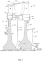
- FIG. 1 is a cross-sectional view depicting a portion of the turbine section of a gas turbine engine along the centerline of the engine.
- the turbine section 30, shown is a two stage turbine, although any number of stages may be employed depending on the turbine design. The present disclosure is not limited by the number of stages in the turbine shown.
- Turbine disks 32 are mounted on a shaft (not shown) extending through a bore in turbine disks 32 along the centerline of the engine, as shown.
- a first stage turbine blade 38 is attached to first stage disk 36, while second stage turbine blade 42 is attached to second stage disk 40.
- a vane 410 extends from a casing 420.
- the inner surface of casing 420 forms a liner 430 for the hot gases of combustion that flow in the gas flow path.
- the first stage turbine blade 38, the second stage turbine blade 42 and the vane 410 extend into the hot gas flow path.
- the vane 410 is stationary and serves to direct the hot gas flow while turbine blades 38, 42 mounted on disks 36, 40 rotate as the hot gases impinge on them, extracting energy to operate the engine.
- Sealing elements 34 include a forward seal 44, an aft seal 46, an interstage seal 48.
- the sealing elements 34 along with a stage 1 aft blade retainer 50 and a stage 2 aft blade retainer 52, serve to seal and complete the compressor air cooling circuits to the turbine blades and nozzles. These sealing elements 34 are in contact with the disks 36,40 and rotate with the disks 36,40.
- Interstage seal 48 is positioned inboard of vane 410 and between the first stage disk 36 and the second stage disk 40. Also shown are optional aft blade retainers 50, 52 that lock the blades 38,42 to the disks 36,40, respectively. The design of such retainers will vary dependent on engine design, with some engine designs not requiring them.
- sealing elements 34 and aft blade retainers 50,52 are heated to the temperatures of the cooling circuit air they direct.
- the parts closest to the combustion path are also heated by conductive heat transfer from the combustion path parts.
- the rim of the turbine disks 36,40 are conductively heated by the turbine blades 38, 42. Contaminants in the cooling air deposit on the surfaces of the disks 36,40, sealing elements 34, and aft blade retainers 50,52 that form the cooling cavities and are the source of contamination at elevated temperatures.
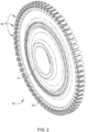
- FIG. 2 is a perspective view of a gas turbine engine disk 82, such as first stage disk 36 or second stage disk 40 of FIG. 1 , which is typically made of a superalloy material, such as one of the superalloy materials previously discussed.
- the disk 82 includes a hub 74 along typically the engine centerline that includes a bore through which a shaft (not shown) extends.
- the disk includes dovetail slots 86 along the disk outer periphery into which the turbine blades (e.g., turbine blades 38,42 from FIG. 1 ) are inserted.
- a web section 78 of the disk 82 extends between the outer periphery, where the dovetail slots are located, and the hub 74.
- the disclosed coating including the glass-forming matrix including silica, corrosion resistant particles, and glass-forming additive, may be utilized anywhere along disk 82, including the dovetail slots 86, it finds particular use along the surfaces of web section 78 and the dovetail slots 86, which unlike the bore in hub 74, are directly exposed to the high temperature cooling air.
- FIG. 3 depicts, in cross-section, the coating of the present disclosure deposited on an engine component.
- Corrosion resistant coating 64 is deposited on the surface 62 of substrate 60.
- the substrate 60 may be any component used in a gas turbine engine, such as a turbine engine disks, blades, and/or retainers as described hereinabove.
- the surface 62 can be any surface of an engine component, for example, the surface 62 can be a web section of a turbine disk (as shown in FIG. 2 ).
- the substrate 60 comprises a superalloy based on nickel, cobalt, iron or a combination thereof.
- the corrosion resistant coating 64 includes one or more corrosion resistant particles 65 dispersed throughout a matrix 63.
- Matrix forming materials preferably comprise a silicon-based material, silicone-based material, or a combination thereof.
- the matrix forming material contains silica.
- silicone resins can be used, such as those with high ceramic yield, including polycarbosilane-based resins, polysilazane-based resins, polysilane-based resins, poly siloxane based resins, or combinations thereof.
- Commercially available resins such as SR 350 TM available from Arkema ® S.A., and DOWSIL TM RSN-0249 Flake Resin available from Dow ® Chemical, can also be used.
- the phosphate binders can be in the form of phosphoric acid or more typically the respective phosphate compounds/compositions, including orthophosphates, pyrophosphates, and other phosphate compounds. These phosphate compounds/compositions can be monobasic, dibasic, tribasic or any combination thereof.
- the phosphate-containing binder component can optionally comprise other binder material, including one or more chromates, molybdates, or similar binder material.
- the matrix material is substantially free of chromates, including hexavalent chromium.
- Corrosion resistant particles are combined with the matrix forming material to form a coating composition.
- corrosion resistant particles can be combined with the matrix forming material and formed into a slurry, which will be discussed in more detail below.
- the corrosion resistant particles may include refractory oxide particles that can impart corrosion resistance to the coating, such as alumina (Al 2 O 3 ), yttrium oxide (Y 2 O 3 ), zirconium oxide (ZrO 2 ), titanium oxide (TiO 2 ) or a combination thereof. While oxides of other metals may be used, such as tungsten, chromium and rhenium, these are less preferred as they are not deemed to be as environmentally friendly as the refractory oxides.
- the corrosion resistant particles include MCrAlX, MCr, MAl, MCrX, or MAlX particles, where M is an element selected from nickel, iron, cobalt, or a combination thereof and X is an element selected from the group consisting of La, Ta, Re, Y, Zr, Hf, Si, B, C or a combination thereof.
- the corrosion resistant particles including MCrAlX, MCr, MAI, MCrX, or MAlX particles may be added to the coating, either alone or in combination with the refractory oxide particles.
- the coating includes CoNiCrAlY particles in combination with zirconia particles. The dispersed zirconia particles and the CoNiCrAlY particles provide the coating with corrosion resistance.
- the corrosion resistant particles can include a plurality of particles having a multimodal distribution.
- the corrosion resistant particles include a plurality of small particles having a median particle size of less than 1 micron, a plurality of medium particles having a particle size of between 2 microns and 8 microns, and a plurality of large particles having a particle size of between 9 microns and 60 microns.
- the plurality of small particles is present in an amount of from about 10 volume % to about 30 volume %
- the plurality of medium particles is present in an amount of from about 30 volume % to about 50 volume %
- the plurality of large particles is present in an amount of from about 30 volume % to about 50 volume%.
- a glass-forming additive is also combined with the matrix material and corrosion resistant particles.
- the glass-forming additive reacts with one or more of the matrix materials (e.g., silicon species such as silica) to facilitate glass formation during heat treatment of the component. Suitable heat treatments include curing, sintering, or use of the coated component.
- the matrix materials e.g., silicon species such as silica
- Suitable heat treatments include curing, sintering, or use of the coated component.
- facilitation and formation of a glassy-phase in the coating provides improved binding strength at high temperatures.
- use of one or more glass-forming additives to form a glassy-phase in the coating diminishes the need for additional sealing top-coats or other coating layers. Furthermore, formation of the glassy-phase improves adhesion strength of the coating.
- the glass-forming additive can include oxides such as iron oxide, gallium oxide, manganese oxide, aluminum oxide, nickel oxide, titanium oxide, boron oxide, alkaline earth oxides, or a combination thereof.
- the glass-forming additive can also include iron, aluminum, nickel, alloys thereof, or a combination thereof.
- the glass-forming additive includes boron, such as elemental boron, an unoxidized boron in a boron alloy or compound, or a combination thereof.
- boron and silicon species e.g., silica
- the glass-forming additive can include a powder having plurality of particles.
- the particles of the glass-forming additive are selected such that the overall particle size distribution of the glass-forming additive particles are much smaller than the corrosion resistant particles.
- the glass-forming additive can include a plurality of particles having particle sizes in the range of from about 50 nm to about 200 nm.
- the glass-forming additive is present in the slurry in an amount of from about 0.01wt.% to about 0.07wt.%, such as about 0.05wt.% based on the total weight of the slurry.
- the components e.g., the matrix, corrosion resistant particles, and glass-forming additive
- the components are substantially free from harmful chromates, such as hexavalent chromium.
- a nucleating agent may also be present in the coating slurry.
- Components coated with certain glass matrix particulate composite coatings can operate at temperatures lower than glass transition temperature.
- Glass transition temperature is the temperature where the macro-mobility of glass structure is observed. Normally, the glass transition temperature is lower than the glass melting (formation) temperature. Therefore, the operating temperature of the coated components is restricted well below the processing temperature of the coating. Interaction of nucleating agents with the glass matrix leads to the formation of nanocrystalline structures throughout the glass matrix. Formation of such nanocrystalline structures allows the coating to be used on components subjected to higher service temperatures, as the melting temperatures of these crystalline phases are higher than amorphous phases of similar compositions.
- nucleating agents include noble metals, such as ruthenium (Ru), rhodium (Rh), palladium (Pd), silver (Ag), osmium (Os), iridium (Ir), platinum (Pt) and gold (Au), fluorides, titanium dioxide, phosphorus pentoxide, chromium (III) oxide, or a combination thereof.
- Ru ruthenium
- Rh rhodium
- Pd palladium
- silver Ag
- Ir iridium
- platinum Pt
- Au gold
- fluorides titanium dioxide, phosphorus pentoxide, chromium (III) oxide, or a combination thereof.
- the matrix forming material, corrosion resistant particles, and glass-forming additive can be combined and dispersed in a carrier fluid to form a slurry.
- the slurry viscosity can then be adjusted by either adding liquid or adding additional particles to the mixture.
- one or more viscosity modifiers can be added to the slurry.
- Suitable viscosity modifiers include polyethylene glycol (PEG), dimethylsiloxane, silicone oil, phthalates, adipates, glycerin, or a combination thereof.
- PEG polyethylene glycol
- dimethylsiloxane silicone oil
- phthalates phthalates
- adipates glycerin
- glycerin glycerin
- the viscosity should be adjusted to be very low, whereas if the slurry is to be applied as a gel, using, for example, a doctor blade to adjust the thickness, then liquid should be removed so that the slurry does not flow readily. Even more liquid should be removed if the slurry is to be formed into a tape. In the last two examples, the final viscosity adjustment may be made after mixing is complete. Regardless of the intended method of application, the mixture is thoroughly agitated. Agitation can be accomplished by any convenient method. Optionally, surfactants and dispersants may also be added to the slurry depending on the method of application.
- FIG. 4 illustrates a flowchart for a method (200) of coating a metal component with the corrosion resistant coating disclosed herein.
- the method includes disposing a corrosion resistant coating on the surface of a metal component.
- the coating includes a matrix, corrosion resistant particles, and glass-forming additive.
- the coating may be applied by any known coating technique, including, but not limited to brushing, rolling, spraying, and dipping.
- the corrosion resistant coating is disposed by spraying.
- a coating slurry can be sprayed onto a surface of the component.
- the viscosity of the coating slurry can be adjusted so that the coating can easily be sprayed.
- the slurry is continuously agitated by placing it on a ball mill until it is ready for application.
- the slurry can be pneumatically agitated by using a pot on a spray gun.
- the slurry can be applied using a spray gun having an adjustable orifice. The orifice size should be larger than the largest particles in the slurry.
- the slurry is sprayed at a pressure of about 20-60 psi.
- the corrosion resistant coating is applied to a preselected thickness, with a larger orifice being selected when a thicker coating is desired.
- the corrosion resistant coating can be applied at a coating thickness of from about 50 ⁇ m to about 1,000 ⁇ m, such as from about 100 ⁇ m to about 950 ⁇ m, such as from about 150 ⁇ m to about 900 ⁇ m, such as from about 200 ⁇ m to about 850 ⁇ m, such as from about 250 ⁇ m to about 800 ⁇ m, such as from about 300 ⁇ m to about 750 ⁇ m, such as from about 350 ⁇ m to about 700 ⁇ m, such as from about 400 ⁇ m to about 650 ⁇ m, such as from about 450 ⁇ m to about 600 ⁇ m.
- the coating can be applied to such thicknesses as a single layer, or can be applied as a plurality of distinct layers to achieve an overall thickness in these ranges.
- the metal component prior to applying the corrosion resistant coating on the surface of the metal component, can be pretreated mechanically, chemically, or both to make the surface more receptive for the corrosion resistant coating.
- Suitable pretreatment methods include grit blasting, with or without masking of surfaces that are not to be subjected to grit blasting, micromachining, shot peening, laser etching, treatment with chemical etchants such as those containing hydrochloric acid, hydrofluoric acid, nitric acid, ammonium bifluorides and mixtures thereof, treatment with water under pressure (i.e., water jet treatment), with or without loading with abrasive particles, as well as various combinations of these methods.
- the surface of the metal component is pretreated by grit blasting where the surface is subjected to the abrasive action of silicon carbide particles, steel particles, alumina particles or other types of abrasive particles.
- These particles used in grit blasting are typically alumina particles and typically have a particle size from about 600 to about 35 mesh (from about 25 to about 500 micrometers), more typically from about 360 to about 35 mesh (from about 35 to about 500 micrometers).
- Other suitable pretreatment methods can include shot-peening and/or laser shock peening.
- One or more pretreatment methods can be utilized. For example, certain embodiments can include pretreating the surface via shot-peening followed by grit blasting.
- Drying can be accomplished via any suitable method. Drying can remove unbound water or provide solvent evaporation from the applied slurry coating. Drying can take place at ambient temperature or the article can be placed in an oven and dried at a temperature greater than ambient. In other embodiments, the environmental humidity may be adjusted to facility drying of the slurry. For example, in embodiments the coated component can be heated to a temperature of 100°C for about 60 minutes to dry the applied coating.
- the coating is heat treated. Suitable heat treatments include curing, sintering, or use of the coated component at an elevated temperature.
- the coating component can be heated to drive off unbound water and to cure the coating.
- heat can be applied to the surface of the coated component to cure the coating or facilitate curing of the coating.
- heat may be applied to the surface to decrease the time required to cure.
- the coated component can be heated to a temperature of about 800°C or greater for time period of from about 30 minutes to 90 minutes, such as about 60 minutes to cure the coating.
- the coated component can be subjected to more than one curing treatment or heat treatment.
- heating or curing the coated component can take place in situ, such as during operation of the part, facilitating on-wing repair.
- the coating can be subjected to an initial treatment prior to use to dry and/or partially cure the coating, and the curing process is completed while the component is in use in an elevated temperature environment.
- a component in the turbine section of a turbine engine may experience elevated temperatures sufficient to complete curing of the coating during the first engine cycle following engine service.
- a corrosion resistant coating comprising: a matrix; corrosion resistant particles dispersed throughout the matrix; and a glass-forming additive, wherein the glass-forming additive and one or more materials in the matrix form a glassy-phase when heat treated.
- the corrosion resistant particles comprise Al 2 O 3 , Y 2 O 3 , ZrO 2 , TiO 2 , or a combination thereof.
- the corrosion resistant particles comprise MAl particles, MAlX particles, MCr particles, MCrX particles, MCrAlX particles, or a combination thereof, where M is an element selected from nickel, iron, cobalt, or a combination thereof and X is an element selected from La, Ta, Re, Y, Zr, Hf, Si, B, C, or a combination thereof.
- the matrix comprises a silicon-based matrix, a silicone-based matrix, or a combination thereof.
- the glass-forming additive comprises one or more metals or oxides of iron, one or more metals or oxides of aluminum, one or more metals or oxides of boron, one or more metals or oxides of nickel, or a combination thereof.
- any preceding clause further comprising a silicone-based sealant layer, wherein the silicone-based sealant layer is substantially free of the corrosion resistant particles.
- the corrosion resistant particles comprise a plurality of small particles having a median particle size of less than 1 micron, a plurality of medium particles having a particle size of between 2 microns and 8 microns, and a plurality of large particles having a particle size of between 9 microns and 60 microns, wherein the plurality of small particles is present in an amount of from about 10 volume % to about 30 volume %, the plurality of medium particles is present in an amount of from about 30 volume % to about 50 volume %, and the plurality of large particles is present in an amount of from about 30 volume % to about 50 volume%.
- a corrosion resistant gas turbine engine component comprising a turbine engine component having a corrosion resistant coating disposed thereon, the corrosion resistant coating comprising: a matrix; corrosion resistant particles dispersed throughout the matrix; and a glass-forming additive, wherein the glass-forming additive reacts with one or more materials in the matrix to form a glassy-phase when heat treated.
- corrosion resistant particles comprise Al 2 O 3 , Y 2 O 3 , ZrO 2 , TiO 2 , or a combination thereof.
- the corrosion resistant particles comprise Mal particles, MAlX particles, MCr particles, MCrX particles, MCrAlX particles, or a combination thereof, where M is an element selected from nickel, iron, cobalt or a combination thereof and X is an element selected from La, Ta, Re, Y, Zr, Hf, Si, B, C, or a combination thereof.
- the matrix comprises a silicon-based matrix, a silicone-based matrix, or a combination thereof.
- the glass-forming additive comprises one or more metals or oxides of iron, one or more metals or oxides of aluminum, one or more metals or oxides of boron, one or more metals or oxides of nickel, or a combination thereof.
- the corrosion resistant coating further comprises a nucleating agent.
- the corrosion resistant particles comprise a plurality of small particles having a median particle size of less than 1 micron, a plurality of medium particles having a particle size of between 2 microns and 8 microns, and a plurality of large particles having a particle size of between 9 microns and 60 microns, wherein the plurality of small particles is present in an amount of from about 10 volume % to about 30 volume %, the plurality of medium particles is present in an amount of from about 30 volume % to about 50 volume %, and the plurality of large particles is present in an amount of from about 30 volume % to about 50 volume%.
- gas turbine engine component comprises a nickel-based alloy, a cobalt-based alloy, or a combination thereof.
- gas turbine engine component comprises a compressor spool, turbine disk, seal, or shaft.
- a method for coating a metal component comprising: disposing a coating composition on a surface of the metal component, the coating composition comprising: a matrix material; corrosion resistant particles; and a glass-forming additive; and heat treating the coating composition to form a coated metal component, wherein the glass-forming additive and one or more materials in the matrix material react during heat treating to form a glassy-phase.
Landscapes
- Chemical & Material Sciences (AREA)
- Organic Chemistry (AREA)
- Engineering & Computer Science (AREA)
- Chemical Kinetics & Catalysis (AREA)
- Materials Engineering (AREA)
- Physics & Mathematics (AREA)
- Thermal Sciences (AREA)
- General Chemical & Material Sciences (AREA)
- Mechanical Engineering (AREA)
- Metallurgy (AREA)
- Inorganic Chemistry (AREA)
- Wood Science & Technology (AREA)
- Life Sciences & Earth Sciences (AREA)
- Health & Medical Sciences (AREA)
- Medicinal Chemistry (AREA)
- Polymers & Plastics (AREA)
- Ceramic Engineering (AREA)
- Other Surface Treatments For Metallic Materials (AREA)
Applications Claiming Priority (1)
| Application Number | Priority Date | Filing Date | Title |
|---|---|---|---|
| US17/487,507 US20230101282A1 (en) | 2021-09-28 | 2021-09-28 | Anti-corrosion coatings |
Publications (1)
| Publication Number | Publication Date |
|---|---|
| EP4155351A1 true EP4155351A1 (de) | 2023-03-29 |
Family
ID=83192175
Family Applications (1)
| Application Number | Title | Priority Date | Filing Date |
|---|---|---|---|
| EP22193784.0A Pending EP4155351A1 (de) | 2021-09-28 | 2022-09-02 | Korrosionsschutzbeschichtungen |
Country Status (3)
| Country | Link |
|---|---|
| US (1) | US20230101282A1 (de) |
| EP (1) | EP4155351A1 (de) |
| CN (1) | CN115873498A (de) |
Families Citing this family (1)
| Publication number | Priority date | Publication date | Assignee | Title |
|---|---|---|---|---|
| US20250257694A1 (en) * | 2022-11-01 | 2025-08-14 | General Electric Company | Gas turbine engine |
Citations (5)
| Publication number | Priority date | Publication date | Assignee | Title |
|---|---|---|---|---|
| US20060127694A1 (en) * | 2004-12-15 | 2006-06-15 | Hazel Brian T | Corrosion resistant coating composition, coated turbine component and method for coating same |
| US20060204665A1 (en) * | 2005-03-10 | 2006-09-14 | Buczek Matthew B | Liquid electrostatic coating composition comprising corrosion resistant metal particulates and method for using same |
| US20070128447A1 (en) * | 2005-12-02 | 2007-06-07 | General Electric Company | Corrosion inhibiting ceramic coating and method of application |
| US20110076410A1 (en) * | 2009-09-30 | 2011-03-31 | Andrew Jay Skoog | Method for making strain tolerant corrosion protective coating compositions and coated articles |
| US20190119803A1 (en) * | 2017-10-20 | 2019-04-25 | United Technologies Corporation | Oxidation resistant bond coat layers, processes for coating articles, and their coated articles |
Family Cites Families (11)
| Publication number | Priority date | Publication date | Assignee | Title |
|---|---|---|---|---|
| US5938834A (en) * | 1996-12-20 | 1999-08-17 | Ford Motor Company | Water-based paint including glass particulate |
| US6497920B1 (en) * | 2000-09-06 | 2002-12-24 | General Electric Company | Process for applying an aluminum-containing coating using an inorganic slurry mix |
| EP1484427A3 (de) * | 2003-06-06 | 2005-10-26 | General Electric Company | Deckschicht für Turbinenleitschaufel und Verfahren zu ihrer Herstellung |
| US20070088111A1 (en) * | 2005-08-26 | 2007-04-19 | Ppg Industries Ohio, Inc. | Coating compositions exhibiting corrosion resistance properties, related coated substrates, and methods |
| US7955694B2 (en) * | 2006-06-21 | 2011-06-07 | General Electric Company | Strain tolerant coating for environmental protection |
| US7951459B2 (en) * | 2006-11-21 | 2011-05-31 | United Technologies Corporation | Oxidation resistant coatings, processes for coating articles, and their coated articles |
| US8916005B2 (en) * | 2007-11-15 | 2014-12-23 | General Electric Company | Slurry diffusion aluminide coating composition and process |
| GB201203529D0 (en) * | 2012-02-29 | 2012-04-11 | Pilkington Group Ltd | Fire resistant glazings |
| US9394448B2 (en) * | 2012-11-09 | 2016-07-19 | Praxair S.T. Technology, Inc. | Chromate-free ceramic coating compositions |
| US11155721B2 (en) * | 2017-07-06 | 2021-10-26 | General Electric Company | Articles for high temperature service and related method |
| US11149168B2 (en) * | 2019-07-02 | 2021-10-19 | The Boeing Company | Surface activation for sealant adhesion on surfaces |
-
2021
- 2021-09-28 US US17/487,507 patent/US20230101282A1/en active Pending
-
2022
- 2022-09-02 EP EP22193784.0A patent/EP4155351A1/de active Pending
- 2022-09-28 CN CN202211191087.6A patent/CN115873498A/zh active Pending
Patent Citations (5)
| Publication number | Priority date | Publication date | Assignee | Title |
|---|---|---|---|---|
| US20060127694A1 (en) * | 2004-12-15 | 2006-06-15 | Hazel Brian T | Corrosion resistant coating composition, coated turbine component and method for coating same |
| US20060204665A1 (en) * | 2005-03-10 | 2006-09-14 | Buczek Matthew B | Liquid electrostatic coating composition comprising corrosion resistant metal particulates and method for using same |
| US20070128447A1 (en) * | 2005-12-02 | 2007-06-07 | General Electric Company | Corrosion inhibiting ceramic coating and method of application |
| US20110076410A1 (en) * | 2009-09-30 | 2011-03-31 | Andrew Jay Skoog | Method for making strain tolerant corrosion protective coating compositions and coated articles |
| US20190119803A1 (en) * | 2017-10-20 | 2019-04-25 | United Technologies Corporation | Oxidation resistant bond coat layers, processes for coating articles, and their coated articles |
Also Published As
| Publication number | Publication date |
|---|---|
| US20230101282A1 (en) | 2023-03-30 |
| CN115873498A (zh) | 2023-03-31 |
Similar Documents
| Publication | Publication Date | Title |
|---|---|---|
| JP5160194B2 (ja) | 耐酸化性を得るためのセラミック耐食性コーティング | |
| EP1870493A2 (de) | Dehnungstolerante Beschichtung zu Umweltschutzzwecken | |
| EP1798311B1 (de) | Dehnungstolerante Korrosionschutzschicht | |
| US7749569B2 (en) | Methods for improving corrosion and oxidation resistance to the under platform region of a gas turbine blade | |
| US7776143B2 (en) | Particulate corrosion resistant coating composition | |
| US7666515B2 (en) | Turbine component other than airfoil having ceramic corrosion resistant coating and methods for making same | |
| US20090047135A1 (en) | Layered corrosion resistant coating for turbine blade environmental protection | |
| EP1793015A2 (de) | Keramische Korrosionsschutzbeschichtung und Verfahren zum Aufbringen | |
| EP2112253A2 (de) | Verfahren zur Wiederherstellung eines Artikels | |
| EP1939325A2 (de) | Dehnungstolerante Korrosionsschutzschicht und Bandverfahren zum Auftragen | |
| EP1700929A1 (de) | Flüssige elektrostatische Beschichtungszusammensetzung, die korrosionsbeständige beschichtete metallische winzige Partikeln umfasst, und seine Verwendungsvefahren | |
| US20230101282A1 (en) | Anti-corrosion coatings | |
| EP3406759B1 (de) | Grüne reparatur von oxidations- und korrosionsbeständigen beschichtungen | |
| WO2010134918A1 (en) | Methods for improving corrosion and oxidation resistance to the under platform region of a gas turbine blade | |
| WO2010134917A1 (en) | Corrosion resistant articles | |
| US20130230406A1 (en) | Corrosion Resistant Articles |
Legal Events
| Date | Code | Title | Description |
|---|---|---|---|
| PUAI | Public reference made under article 153(3) epc to a published international application that has entered the european phase |
Free format text: ORIGINAL CODE: 0009012 |
|
| STAA | Information on the status of an ep patent application or granted ep patent |
Free format text: STATUS: THE APPLICATION HAS BEEN PUBLISHED |
|
| AK | Designated contracting states |
Kind code of ref document: A1 Designated state(s): AL AT BE BG CH CY CZ DE DK EE ES FI FR GB GR HR HU IE IS IT LI LT LU LV MC MK MT NL NO PL PT RO RS SE SI SK SM TR |
|
| STAA | Information on the status of an ep patent application or granted ep patent |
Free format text: STATUS: REQUEST FOR EXAMINATION WAS MADE |
|
| 17P | Request for examination filed |
Effective date: 20230928 |
|
| RBV | Designated contracting states (corrected) |
Designated state(s): AL AT BE BG CH CY CZ DE DK EE ES FI FR GB GR HR HU IE IS IT LI LT LU LV MC MK MT NL NO PL PT RO RS SE SI SK SM TR |