EP4155503A1 - Procédés de détection acoustique de fonctionnement anormal d'infrastructures industrielles d'hydrocarbures et de puits d'hydrocarbures comprenant des contrôleurs qui exécutent les procédés - Google Patents
Procédés de détection acoustique de fonctionnement anormal d'infrastructures industrielles d'hydrocarbures et de puits d'hydrocarbures comprenant des contrôleurs qui exécutent les procédés Download PDFInfo
- Publication number
- EP4155503A1 EP4155503A1 EP22191210.8A EP22191210A EP4155503A1 EP 4155503 A1 EP4155503 A1 EP 4155503A1 EP 22191210 A EP22191210 A EP 22191210A EP 4155503 A1 EP4155503 A1 EP 4155503A1
- Authority
- EP
- European Patent Office
- Prior art keywords
- acoustic output
- anomalous
- hydrocarbon
- acoustic
- sounds
- Prior art date
- Legal status (The legal status is an assumption and is not a legal conclusion. Google has not performed a legal analysis and makes no representation as to the accuracy of the status listed.)
- Pending
Links
Images



Classifications
-
- E—FIXED CONSTRUCTIONS
- E21—EARTH OR ROCK DRILLING; MINING
- E21B—EARTH OR ROCK DRILLING; OBTAINING OIL, GAS, WATER, SOLUBLE OR MELTABLE MATERIALS OR A SLURRY OF MINERALS FROM WELLS
- E21B47/00—Survey of boreholes or wells
- E21B47/09—Locating or determining the position of objects in boreholes or wells, e.g. the position of an extending arm; Identifying the free or blocked portions of pipes
- E21B47/095—Locating or determining the position of objects in boreholes or wells, e.g. the position of an extending arm; Identifying the free or blocked portions of pipes by detecting an acoustic anomalies, e.g. using mud-pressure pulses
-
- E—FIXED CONSTRUCTIONS
- E21—EARTH OR ROCK DRILLING; MINING
- E21B—EARTH OR ROCK DRILLING; OBTAINING OIL, GAS, WATER, SOLUBLE OR MELTABLE MATERIALS OR A SLURRY OF MINERALS FROM WELLS
- E21B47/00—Survey of boreholes or wells
- E21B47/10—Locating fluid leaks, intrusions or movements
- E21B47/107—Locating fluid leaks, intrusions or movements using acoustic means
Definitions
- the present disclosure relates generally to methods of acoustically detecting anomalous operation of hydrocarbon industrial infrastructure and to hydrocarbon wells that include controllers that perform the methods.
- Acoustic monitoring may be utilized to detect sounds emitted from and/or by hydrocarbon industrial infrastructure, such as a hydrocarbon well. These sounds may be generated by various activities performed at, or within, the hydrocarbon industrial infrastructure. As examples, opening and closing of valves, operation of pumps, fluid flows, and the like each may generate corresponding sounds that may be detected at the hydrocarbon industrial infrastructure. Some sounds may be generated during normal operation of the hydrocarbon industrial infrastructure. However, other sounds may be generated by, or indicative of, undesired, changing, and/or anomalous operation of the hydrocarbon industrial infrastructure. A trained operator may, in some instances, hear these other sounds and respond appropriately. However, all operators may not have this ability.
- Methods of acoustically detecting anomalous operation of hydrocarbon industrial infrastructure and hydrocarbon wells that include controllers that perform the methods are disclosed herein.
- the detection is via analysis of an acoustic output from the hydrocarbon industrial infrastructure.
- the methods include receiving the acoustic output, which includes a plurality of sounds and a corresponding recording time for each sound of the plurality of sounds.
- the methods also include analyzing the acoustic output with an anomaly detection algorithm to identify an anomalous sound of the plurality of sounds.
- the anomalous sound is indicative of anomalous operation of the hydrocarbon industrial infrastructure.
- the methods further include responding to the anomalous operation of the hydrocarbon industrial infrastructure. The responding is performed responsive to the anomaly detection algorithm identifying the anomalous sound.
- the hydrocarbon wells include a wellbore that extends within a subsurface region.
- the hydrocarbon wells also include an acoustic monitoring system configured to monitor an acoustic output from the hydrocarbon well.
- the hydrocarbon wells further include the controller, which is programmed to characterize the acoustic output according to the methods.
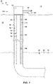
- FIG. 1 is a schematic illustration of examples of hydrocarbon industrial infrastructure, in the form of hydrocarbon wells 30, which include controllers 140 programmed to perform methods 200, according to the present disclosure.
- elements that are likely to be included in a particular embodiment are illustrated in solid lines, while elements that are optional are illustrated in dashed lines.
- elements that are shown in solid lines may not be essential to all embodiments and, in some embodiments, may be omitted without departing from the scope of the present disclosure.
- hydrocarbon wells 30 include a wellbore 40 that extends within a subsurface region 20.
- Wellbore 40 also may be referred to herein as extending between a surface region 10 and subsurface region 20.
- Subsurface region 20 may include a subterranean formation 22, which may include liquids 24 and/or gasses 26.
- Wellbore 40 may extend within the subterranean formation and may produce, or may be utilized to produce, a produced fluid stream 32, which may include liquids 24 and/or gasses 26, from the subterranean formation.
- Examples of hydrocarbon well 30 include a natural gas well and/or an oil well.
- Hydrocarbon wells 30 also include an acoustic monitoring system 130.
- Acoustic monitoring system 130 may be adapted, configured, designed, and/or constructed to monitor an acoustic output from, sounds produced from, noises produced by, and/or vibrations produced by hydrocarbon wells 30.
- the acoustic output may include and/or may be defined by a plurality of sounds, noises, and/or vibrations produced by the hydrocarbon wells, and the acoustic monitoring system may be configured to monitor, to detect, to quantify, and/or to record the plurality of sounds.
- the phrase "acoustic output” may refer to any suitable vibration that may be emitted from, produced from, propagated by, and/or generated by hydrocarbon well 30. Additionally or alternatively, the acoustic output may refer to any suitable vibration that may be received by, detected by, and/or quantified by acoustic monitoring system 130.
- the acoustic output may have any suitable frequency, frequency range, amplitude, and/or amplitude range.
- the acoustic output may be audible and/or may be detected by the human ear. Such audible acoustic output may, for example, have a frequency range of 10 Hertz (Hz) to 20 kilohertz (kHz).
- the acoustic output may have frequencies higher and/or lower than the audible frequency range.
- the acoustic output may have frequencies of at least 0.001 Hz, at least 0.005 Hz, at least 0.01 Hz, at least 0.05 Hz, at least 0.1 Hz, at least 1 Hz, at least 2 Hz, at least 4 Hz, at least 6 Hz, at least 8 Hz, at least 10 Hz, at least 25 Hz, at least 50 Hz, at least 100 Hz, at least 500 Hz, at least 1 kHz, at least 5 kHz, at least 10 kHz, at least 20 kHz, at least 30 kHz, at least 40 kHz, at least 50 kHz, at most 100 kHz, at most 90 kHz, at most 80 kHz, at most 70 kHz, at most 60 kHz, at most 50 kHz, at most 40 kHz, at most 30 k
- this may include monitoring the acoustic output, including an amplitude of the acoustic output and/or a frequency of the acoustic output, as a function of time, such as during production of produced fluid stream 32 from the hydrocarbon well.
- acoustic monitoring system 130 may be configured to detect the acoustic output from hydrocarbon wells 30 at least while the hydrocarbon wells produce produced fluid stream 32.
- acoustic monitoring system 130 includes a surface acoustic sensor 132, which may be configured to detect and/or to monitor the acoustic output.
- the surface acoustic sensor include a surface microphone and/or a surface vibration sensor.
- surface acoustic sensor 132 may include and/or be a point surface acoustic sensor, such as may be configured to detect the acoustic output at a given location.
- surface acoustic sensor 132 may include and/or be a distributed surface acoustic sensor, such as may be configured to detect the acoustic output along a length thereof.
- the acoustic monitoring system includes a downhole acoustic sensor 134, which may be positioned and/or may extend along a length of wellbore 40.
- An example of the downhole acoustic sensor includes a distributed acoustic sensor 136, such as a fiber optic cable, which may extend along at least a fraction of the length of the wellbore. This may include extending linearly along the length of the wellbore, extending within a given region of the wellbore, being attached to a structure, such as production tubing 70, which extends within the wellbore, and/or being wrapped around the structure that extends within the wellbore.
- the downhole acoustic sensor includes at least one discrete downhole acoustic sensor 138, or even a plurality of discrete downhole acoustic sensors 138.
- the discrete downhole acoustic sensor include a downhole microphone and/or a downhole vibration sensor.
- Hydrocarbon wells 30 further include a controller 140.
- Controller 140 may be adapted, configured, designed, constructed, and/or programmed to control the operation of hydrocarbon wells 30 and/or of at least one other component of hydrocarbon wells 30. This may include controlling the operation of, receiving one or more signals from, and/or providing one or more signals to acoustic monitoring system 130.
- controller 140 may be programmed to control the operation of hydrocarbon wells 30 according to, utilizing, and/or by performing any suitable step and/or steps of methods 200, which are discussed in more detail herein. Stated another way, controller 140 may be programmed to characterize the acoustic output from the hydrocarbon well by performing any suitable step and/or steps of methods 200.
- Controller 140 may include and/or be any suitable structure, device, and/or devices that may be adapted, configured, designed, constructed, and/or programmed to perform the functions discussed herein. This may include controlling the operation of the at least one other component of hydrocarbon wells 30, such as via performing one or more steps of methods 200.
- controller 140 may include one or more of an electronic controller, a dedicated controller, a special-purpose controller, a personal computer, a special-purpose computer, a display device, a touch screen display, a logic device, a memory device, and/or a memory device having computer-readable storage media.
- the computer-readable storage media when present, also may be referred to herein as non-transitory computer-readable storage media.
- This non-transitory computer-readable storage media may include, define, house, and/or store computer-executable instructions, programs, and/or code; and these computer-executable instructions may direct hydrocarbon wells 30 and/or controller 140 thereof to perform any suitable portion, or subset, of methods 200. Examples of such non-transitory computer-readable storage media include CD-ROMs, disks, hard drives, flash memory, etc.
- storage, or memory, devices and/or media having computer-executable instructions, as well as computer-implemented methods and other methods according to the present disclosure are considered to be within the scope of subject matter deemed patentable in accordance with Section 101 of Title 35 of the United States Code.
- hydrocarbon wells 30 may include production tubing 70, which may extend within wellbore 40 and/or may define a tubing conduit 72.
- hydrocarbon wells 30 also may include a casing string 50.
- Casing string 50 when present, may extend within wellbore 40 and/or may define a casing conduit 52.
- production tubing 70 may extend within casing conduit 52, and/or casing string 50 and production tubing 70 may define an annular space 60 therebetween.
- Downhole acoustic sensor 134 when present, may be positioned and/or may extend within casing conduit 52, within tubing conduit 72, and/or within annular space 60.
- FIG. 1 illustrates hydrocarbon industrial infrastructure 28 in the form of hydrocarbon wells 30, it is within the scope of the present disclosure that acoustic monitoring systems 130, controllers 140 and/or methods 200, which are disclosed herein, may be included in and/or utilized with any suitable hydrocarbon industrial infrastructure 28.
- suitable hydrocarbon industrial infrastructure 28 may, in some examples, be associated with, utilized with, and/or proximate hydrocarbon wells 30. Additionally or alternatively, such suitable hydrocarbon industrial infrastructure 28 may, in some examples, be distinct from, separate from, and/or not utilized with hydrocarbon wells 30.
- suitable hydrocarbon industrial infrastructure 28 include pipelines, flow lines, wellbores utilized for gas injection to maintain subsurface pressures, wellbores utilized for gas, such as carbon dioxide, sequestration, risers, storage vessels, and/or processing equipment.
- Such hydrocarbon industrial infrastructure 28 may contain, house, process, and/or convey hydrocarbons, liquid hydrocarbons, gaseous hydrocarbons, and/or solid hydrocarbons. Additionally or alternatively, such hydrocarbon industrial infrastructure 28 may contain, house, process, and/or convey other materials, which may be present within produced hydrocarbons and/or utilized during storage, conveyance, and/or processing of such hydrocarbons. Examples of such other materials include water, a gas, nitrogen, and/or carbon dioxide.
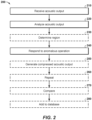
- FIG. 2 is a flowchart depicting examples of methods 200 of acoustically detecting anomalous operation of hydrocarbon industrial infrastructure, according to the present disclosure, such as hydrocarbon industrial infrastructure 28 of FIG. 1 .
- Methods 200 detect anomalous operation of the hydrocarbon industrial infrastructure via analysis of an acoustic output from the hydrocarbon industrial infrastructure.
- the acoustic output may be monitored, detected, quantified, and/or recorded by an acoustic monitoring system, such as acoustic monitoring system 130 of FIG. 1 .
- Methods 200 include receiving an acoustic output at 210 and analyzing the acoustic output at 220. Methods 200 may include determining a region at 230 and include responding to anomalous operation at 240. Methods 200 further may include generating compressed acoustic output at 250, repeating at 260, comparing at 270, and/or adding to a database at 280.
- Receiving the acoustic output at 210 may include receiving any suitable acoustic output from the hydrocarbon industrial infrastructure, detected at the hydrocarbon industrial infrastructure, generated by the hydrocarbon industrial infrastructure, and/or generated from the hydrocarbon industrial infrastructure.
- the acoustic output may include a plurality of sounds and a corresponding recording time for each sound of the plurality of sounds.
- the receiving at 210 may be performed in any suitable manner.
- the receiving at 210 may include receiving an acoustic data file that is representative of the acoustic output.
- the receiving at 210 may include receiving the acoustic output, such as via the acoustic data file, subsequent to detection of the acoustic output at the hydrocarbon industrial infrastructure.
- the receiving at 210 may include recording and/or detecting the acoustic output utilizing an acoustic monitoring system of the hydrocarbon industrial infrastructure.
- the receiving at 210 may include receiving the acoustic output in real-time, receiving the acoustic output during operation of the hydrocarbon industrial infrastructure, receiving the acoustic output at least partially concurrently with detection of the acoustic output at the hydrocarbon industrial infrastructure, and/or receiving the acoustic output at least partially responsive to detection of the acoustic output at the hydrocarbon industrial infrastructure.
- the acoustic monitoring system may include and/or be a surface acoustic sensor, and the recording and/or detecting may include recording and/or detecting with, via, and/or utilizing the surface acoustic sensor, examples of which are disclosed herein with reference to surface acoustic sensor 132 of FIG. 1 .
- the acoustic monitoring system may include and/or be a downhole acoustic sensor, which may be positioned within a wellbore of a hydrocarbon well that at least partially defines the hydrocarbon industrial infrastructure.
- the recording and/or detecting may include recording and/or detecting with, via, and/or utilizing the downhole acoustic sensor. Examples of the downhole acoustic sensor are disclosed herein with reference to downhole acoustic sensor 134 of FIG. 1 .
- the downhole acoustic sensor may be positioned along a length of the wellbore.
- the downhole acoustic sensor may include and/or be a distributed acoustic sensor that extends along at least a fraction of the length of the wellbore and the recording may include utilizing the distributed acoustic sensor to record and/or detect the acoustic output.
- acoustic monitoring system 130 may include a distributed acoustic sensor that extends along a length of the pipeline and/or flow line. Examples of the distributed acoustic sensor are disclosed herein with reference to distributed acoustic sensor 136 of FIG. 1 .
- the downhole acoustic sensor may include and/or be at least one discrete downhole acoustic sensor.
- the at least one discrete downhole acoustic sensor when utilized, may be positioned at a corresponding location along the length of the wellbore.
- the at least one discrete downhole acoustic sensor may include a plurality of discrete downhole acoustic sensors.
- the plurality of discrete downhole acoustic sensors may be positioned at a corresponding plurality of locations along the length of the wellbore, may be positioned at a plurality of spaced-apart corresponding locations along the length of the wellbore, and/or may be spaced apart along at least a fraction of the length of the wellbore.
- Examples of the at least one discrete downhole acoustic sensor are disclosed herein with reference to discrete downhole acoustic sensors 138.
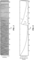
- FIG. 3 An example of the acoustic output, in the form of a spectrogram, is illustrated in FIG. 3 .
- frequency of the acoustic output is indicated on the ordinate, and time is indicated on the abscissa.
- an intensity at each frequency is indicated by color and/or shade, with relatively lighter colors and/or shades being indicative of relatively higher intensities.
- FIG. 3 illustrates a change in operation of the hydrocarbon industrial infrastructure (more specifically in operation of a compressor) between the time period from 0-50 seconds and the time period from 70-100 seconds. More specifically, and as may be qualitatively observed, the spectrogram of FIG.
- methods 200 may be utilized to more quantitatively detect the presence of the change in operation and/or initiation of the change in operation.
- Analyzing the acoustic output at 220 may include analyzing the acoustic output with, via, and/or utilizing an anomaly detection algorithm. This may include analyzing the acoustic output to identify an anomalous sound of the plurality of sounds. The anomalous sound may be indicative of anomalous, unexpected, and/or undesired operation of the hydrocarbon industrial infrastructure. In some examples, the analyzing at 220 may include utilizing the anomaly detection algorithm to identify a plurality of anomalous sounds indicative of a shift to anomalous, unexpected, and/or undesired operation of the hydrocarbon industrial infrastructure. In some examples, the analyzing at 220 may include analyzing the acoustic output utilizing windowed statistical analysis.
- the anomaly detection algorithm may, in some examples, include and/or utilize windowed statistical analysis.
- windowed statistical analysis examples of the anomaly detection algorithm and/or of windowed statistical analysis are disclosed in U.S. Patent No. 8,380,435 , the complete disclosure of which is hereby incorporated by reference.
- Anomaly detection algorithms may compare data within a memory window, which spans a memory window time period of a time-based dataset, to data within a pattern window, which spans a pattern window time period of the time-based dataset.
- the memory window may include a memory window subset of the plurality of sounds
- the pattern window may include a pattern window subset of the plurality of sounds. Examples of the memory window and the pattern window are illustrated in FIG. 4 . As illustrated in FIG. 4 , the memory window time period may be greater than the pattern window time period. As also illustrated in FIG.
- the memory window time period and the pattern window time period may begin at a common leading time, L, with the pattern window time period extending to a pattern window trailing time, P, and the memory window time period extending to a memory window trailing time, M, that predates pattern window trailing time, P.
- the anomaly detection algorithms may indicate anomalous regions of the time-based dataset. This is illustrated in FIG. 5 , which plots both anomaly intensity, A, and a dynamically computed threshold, T, as a function of time. Detection of the anomaly is triggered when the anomaly intensity, A, crosses the threshold, T, or at approximately 57 seconds.
- the acoustic output includes a plurality of sounds; and each sound of the plurality of sounds may be generated in, within, and/or by a corresponding region of the hydrocarbon industrial infrastructure, of the pipeline, of the flow line, and/or of the wellbore.
- the determining at 230 may include determining a corresponding position and/or a corresponding location, along the length of the hydrocarbon industrial infrastructure, for each sound of the plurality of sounds, such as at a given time. Additionally or alternatively, and in some examples, the determining at 230 may include determining a corresponding position and/or a corresponding location, along the length of the hydrocarbon industrial infrastructure, for the anomalous sound, or for at least the anomalous sound.
- the acoustic output may be detected by an acoustic monitoring system that includes a distributed acoustic sensor.
- the determining at 230 may include determining a region of the distributed acoustic sensor utilized to detect each sound of the plurality of sounds. The determined location may be based, at least in part, on the region of the distributed acoustic sensor utilized to detect each sound of the plurality of sounds.
- the distributed acoustic sensor may provide information regarding the time at which a given sound of the plurality of sounds was generated, a location at which the given sound was generated, and/or spectral information about the given sound.
- methods 200 may, in some such examples, be utilized to determine, ascertain, and/or pinpoint timing of the anomalous operation of the hydrocarbon industrial infrastructure, the location of the anomalous operation and/or the physical structure that is the source of the anomalous operation, and/or spectral information regarding the anomalous operation.
- FIG. 6 acoustic output, which is detected by a distributed acoustic sensor, is plotted on the ordinate, and position along the length of a wellbore of a hydrocarbon well is plotted on the abscissa.
- FIG. 7 plots anomaly intensity, as computed via the anomaly detection algorithm, on the ordinate and the position along the length of the wellbore on the abscissa.
- the anomaly detection algorithm indicates a significant increase in the anomaly intensity at positions between 390 and 440 along the length of the wellbore. This increased anomaly intensity may be indicative of, or may be utilized to indicate, anomalous sound generation, and thus anomalous operation of the hydrocarbon well, in this region of the wellbore.
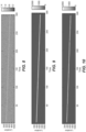
- the acoustic output and the anomaly intensity may be displayed in corresponding spectrograms, as illustrated in FIGs. 8-9 . More specifically, FIGs. 8-9 illustrate location along the length of the wellbore on the ordinate and time on the abscissa. In FIG. 8 , an intensity of acoustic output at a given location and for a given time is indicated by color and/or shade. In FIG. 9 , anomaly intensity of the acoustic output, as computed via the anomaly detection algorithm, is indicated by color and/or shade.
- sounds such as sounds generated by mechanical structures that are fixed in space
- Other sounds may have a variable location and/or may move with time.
- a fluid phase boundary and/or sand may move within the hydrocarbon industrial infrastructure.
- FIGs. 8-9 illustrate an example in which the generated sounds move with time. More specifically, and in the example of FIGs. 8-9 , the sounds move toward the surface (or well top) with time and may, for example, be indicative of a gas bubble that is traveling within the wellbore.
- FIGs. 11-12 illustrate an additional benefit of methods 200. More specifically, FIG. 11 is a spectrogram illustrating another example of position-based acoustic output as a function of time that may be utilized with methods 200, while FIG. 12 is a spectrogram illustrating an example of position-based output from an anomaly detection algorithm (e.g., anomaly intensity) as a function of time that may be generated via analysis of the spectrogram of FIG. 11 utilizing methods 200.
- an anomaly detection algorithm e.g., anomaly intensity
- FIG. 11 the acoustic output generally appears to be random noise.
- FIGs. 11 upon analysis of the spectrogram of FIG. 11 with an anomaly detection algorithm, it becomes clear that, for a specific range of times and within a specific location region, anomalous behavior is occurring.
- FIGs. 11 illustrates an additional benefit of methods 200. More specifically, FIG. 11 is a spectrogram illustrating another example of position-based acoustic output as a function of time that may be
- FIGs. 11-12 illustrate that methods 200 may be utilized to more reliably detect anomalous operation that may not necessarily be immediately visible to the naked eye and/or to less sensitive analysis techniques.
- FIGs. 11-12 also illustrate that methods 200 may be sensitive to anomalous acoustic data, where the anomaly is contained within spatial, temporal, and/or spectral aspects of the acoustic output.
- Responding to anomalous operation at 240 may include responding to the anomalous operation when, responsive to, and/or if the anomaly detection algorithm identifies the anomalous sound.
- the responding at 240 may include responding in any suitable manner.
- the responding at 240 may include responding in real-time, responding during operation of the hydrocarbon industrial infrastructure, and/or responding during, concurrently with, and/or at least partially concurrently with the receiving at 210 and/or the analyzing at 220.
- the responding at 240 may include notifying an operator of the hydrocarbon industrial infrastructure about the anomalous operation of the hydrocarbon industrial infrastructure.
- the responding at 240 may include displaying an anomalous operation indicator that is indicative of anomalous operation of the hydrocarbon industrial infrastructure.
- the responding at 240 may include initiating maintenance of the hydrocarbon industrial infrastructure, replacing a component of the hydrocarbon industrial infrastructure, and/or changing an operational parameter of the hydrocarbon industrial infrastructure.
- the responding at 240 may include initiating the repeating at 260.
- the responding at 240 additionally or alternatively may include changing and/or modifying methods 200, such as is discussed in more detail herein with reference to the repeating at 260. This may include changing a sampling rate of the acoustic output, such as via modification of the receiving at 210.
- methods 200 may include tracking the position and/or location, along the length of the hydrocarbon industrial infrastructure, such as along the length of the wellbore, at which a given sound of the plurality of sounds is generated and/or tracking the position and/or location of the given sound as a function of time. In some such examples, methods 200 further may include generating a compressed acoustic output at 250.
- the generating at 250 may include saving a portion of the acoustic output, storing the portion of the acoustic output, generating a compressed acoustic output file that includes the portion of the acoustic output, displaying the portion of the acoustic output, conveying the portion of the acoustic output to another step within methods 200, and/or utilizing the portion of the acoustic output for other analyses.
- the anomaly detection algorithm may indicate the location of the anomaly at a given point in time.
- the generating at 250 may include retaining, within the compressed acoustic output file, the anomalous sound and a corresponding anomaly position for each corresponding recording time and omit a remainder of the acoustic output. This is illustrated in FIG. 10 .
- Such a configuration may decrease overall storage requirements for acoustic data generated during and/or utilized with methods 200, may facilitate improved display and/or utilization of anomalous sounds, and/or may permit anomalous sounds to be clearly tracked, displayed, and/or stored.
- Repeating at 260 may include repeating any suitable step and/or steps of methods 200 in any suitable manner, in any suitable order, and/or for any suitable purpose.
- the repeating at 260 may include repeating the analyzing at 220 and/or repeating utilizing a modified version of the analyzing at 220.
- the memory window, which is utilized during the analyzing at 220 may be a first memory window that spans a first memory window time period that includes a first memory window subset of the plurality of sounds and the pattern window, which is utilized during the analyzing at 220, may be a first pattern window that spans a first pattern window time period that includes a first pattern window subset of the plurality of sounds.
- the repeating at 260 may include repeating the analyzing at 220 utilizing a second memory window that spans a second memory window time period that includes a second memory window subset of the plurality of sounds and a second pattern window that spans a second pattern window time period that includes a second pattern window subset of the plurality of sounds.
- the first memory window time period may differ from the second memory window time period. As an example, the first memory window time period may be greater than the second memory window time period. Such a configuration may cause methods 200 to be less sensitive to small changes in the acoustic output during the repeating the analyzing at 220 when compared to the analyzing at 220. As another example, the first memory window time period may be less than the second memory window time period. Such a configuration may cause methods 200 to be more sensitive to small changes in the acoustic output during the repeating the analyzing at 220 when compared to the analyzing at 220. As yet another example, the first pattern window time period may be greater than the second pattern window time period.
- Such a configuration may cause methods 200 to be more sensitive to global changes in the acoustic output during the repeating the analyzing at 220 when compared to the analyzing at 220.
- the first pattern window time period may be less than the second pattern window time period.
- Such a configuration may cause methods 200 to be more sensitive to location, time, and/or spectrum-specific changes in the acoustic output during the repeating the analyzing at 220 when compared to the analyzing at 220.
- the analyzing at 220 and the repeating the analyzing at 220 may be performed utilizing the same, or a single, acoustic output from the hydrocarbon industrial infrastructure.
- the analyzing at 220 may be performed utilizing a first acoustic output from the hydrocarbon industrial infrastructure, and the repeating the analyzing at 220 may be performed utilizing a second, or later detected, acoustic output from the hydrocarbon industrial infrastructure.
- the sampling rate, or resolution may differ between the first acoustic output from the hydrocarbon industrial infrastructure and the second acoustic output from the hydrocarbon industrial infrastructure. Such difference in sampling rate, or resolution, may, for example, be caused by and/or responsive to the responding at 240, as discussed in more detail herein.
- Comparing at 270 may include comparing the anomalous sound detected, or as detected, during the analyzing the acoustic output to the anomalous sound detected, or as detected, during the repeating the analyzing the acoustic output. Such a comparison may, for example, permit and/or facilitate improved identification of the anomalous sound and/or of a corresponding source of the anomalous sound.
- Comparing at 270 additionally or alternatively may include comparing the anomalous sound to an anomalous sound database, such as to identify the corresponding source of the anomalous sound.
- the responding at 240 additionally may include notifying the operator of the hydrocarbon industrial infrastructure of the corresponding source of the anomalous sound and/or identifying the corresponding source for the operator. Stated another way, methods 200 further may include identifying the corresponding source of the anomalous sound.
- Adding to the database at 280 may include adding any suitable information to the anomalous sound database.
- the adding at 280 may include adding the anomalous sound to the anomalous sound database.
- the adding at 280 may include adding the corresponding source of the anomalous sound to the anomalous sound database.
- the adding at 280 may include correlating the corresponding source of the anomalous sound to the anomalous sound in and/or within the anomalous sound database.
- hydrocarbon industrial infrastructure and methods which are disclosed herein, have been described in the context of analysis of acoustic output, which may be detected with, via, and/or utilizing an acoustic monitoring system. It is within the scope of the present disclosure that the disclosed hydrocarbon industrial infrastructure and/or methods additionally or alternatively may utilize, or may analyze, one or more other values and/or parameters that may be generated from, by, and/or within the hydrocarbon industrial infrastructure.
- the acoustic monitoring system may be, instead may be, or may more generally be referred to herein as a sensor system; and the acoustic output may be, instead may be, or may more generally be referred to herein as sensor output from the hydrocarbon industrial infrastructure.
- the sensor system may record and/or detect the sensor output in a manner that may be analogous to that disclosed herein with reference to recording and/or detecting the acoustic output utilizing the acoustic monitoring system.
- Examples of sensor output that may be detected and/or quantified by the sensor system and/or that may be analyzed utilizing methods disclosed herein include any suitable physical, mechanical, and/or chemical parameter.
- the sensor output include temperatures, pressures, and/or strains proximate and/or within the hydrocarbon industrial infrastructure.
- several of the illustrative, non-exclusive examples have been discussed and/or presented in the context of flow diagrams, or flow charts, in which the methods are shown and described as a series of blocks, or steps. Unless specifically set forth in the accompanying description, it is within the scope of the present disclosure that the order of the blocks may vary from the illustrated order in the flow diagram, including with two or more of the blocks (or steps) occurring in a different order and/or concurrently. It is also within the scope of the present disclosure that the blocks, or steps, may be implemented as logic, which also may be described as implementing the blocks, or steps, as logics.
- the blocks, or steps may represent expressions and/or actions to be performed by functionally equivalent circuits or other logic devices.
- the illustrated blocks may, but are not required to, represent executable instructions that cause a computer, processor, and/or other logic device to respond, to perform an action, to change states, to generate an output or display, and/or to make decisions.
- the term "and/or" placed between a first entity and a second entity means one of (1) the first entity, (2) the second entity, and (3) the first entity and the second entity.
- Multiple entities listed with “and/or” should be construed in the same manner, i.e., "one or more" of the entities so conjoined.
- Other entities may optionally be present other than the entities specifically identified by the "and/or” clause, whether related or unrelated to those entities specifically identified.
- a reference to "A and/or B,” when used in conjunction with open-ended language such as “comprising” may refer, in one embodiment, to A only (optionally including entities other than B); in another embodiment, to B only (optionally including entities other than A); in yet another embodiment, to both A and B (optionally including other entities).
- These entities may refer to elements, actions, structures, steps, operations, values, and the like.
- the phrase "at least one,” in reference to a list of one or more entities should be understood to mean at least one entity selected from any one or more of the entities in the list of entities, but not necessarily including at least one of each and every entity specifically listed within the list of entities and not excluding any combinations of entities in the list of entities.
- This definition also allows that entities may optionally be present other than the entities specifically identified within the list of entities to which the phrase "at least one" refers, whether related or unrelated to those entities specifically identified.
- At least one of A and B may refer, in one embodiment, to at least one, optionally including more than one, A, with no B present (and optionally including entities other than B); in another embodiment, to at least one, optionally including more than one, B, with no A present (and optionally including entities other than A); in yet another embodiment, to at least one, optionally including more than one, A, and at least one, optionally including more than one, B (and optionally including other entities).
- each of the expressions “at least one of A, B, and C,” “at least one of A, B, or C,” “one or more of A, B, and C,” “one or more of A, B, or C,” and “A, B, and/or C” may mean A alone, B alone, C alone, A and B together, A and C together, B and C together, A, B, and C together, and optionally any of the above in combination with at least one other entity.
- adapted and “configured” mean that the element, component, or other subject matter is designed and/or intended to perform a given function.
- the use of the terms “adapted” and “configured” should not be construed to mean that a given element, component, or other subject matter is simply “capable of' performing a given function but that the element, component, and/or other subject matter is specifically selected, created, implemented, utilized, programmed, and/or designed for the purpose of performing the function.
- elements, components, and/or other recited subject matter that is recited as being adapted to perform a particular function may additionally or alternatively be described as being configured to perform that function, and vice versa.
- the phrase, "for example,” the phrase, “as an example,” and/or simply the term “example,” when used with reference to one or more components, features, details, structures, embodiments, and/or methods according to the present disclosure, are intended to convey that the described component, feature, detail, structure, embodiment, and/or method is an illustrative, non-exclusive example of components, features, details, structures, embodiments, and/or methods according to the present disclosure.
- an object that is at least substantially formed from a material includes objects for which at least 75% of the objects are formed from the material and also includes objects that are completely formed from the material.
- a first length that is at least substantially as long as a second length includes first lengths that are within 75% of the second length and also includes first lengths that are as long as the second length.
- the systems and methods disclosed herein are applicable to the oil, gas, carbon sequestration, and carbon storage industries.
Landscapes
- Physics & Mathematics (AREA)
- Life Sciences & Earth Sciences (AREA)
- Engineering & Computer Science (AREA)
- Geology (AREA)
- Mining & Mineral Resources (AREA)
- Acoustics & Sound (AREA)
- Geophysics (AREA)
- Environmental & Geological Engineering (AREA)
- Fluid Mechanics (AREA)
- General Life Sciences & Earth Sciences (AREA)
- Geochemistry & Mineralogy (AREA)
- Investigating Or Analyzing Materials By The Use Of Ultrasonic Waves (AREA)
Applications Claiming Priority (1)
| Application Number | Priority Date | Filing Date | Title |
|---|---|---|---|
| US202163261478P | 2021-09-22 | 2021-09-22 |
Publications (1)
| Publication Number | Publication Date |
|---|---|
| EP4155503A1 true EP4155503A1 (fr) | 2023-03-29 |
Family
ID=83004791
Family Applications (1)
| Application Number | Title | Priority Date | Filing Date |
|---|---|---|---|
| EP22191210.8A Pending EP4155503A1 (fr) | 2021-09-22 | 2022-08-19 | Procédés de détection acoustique de fonctionnement anormal d'infrastructures industrielles d'hydrocarbures et de puits d'hydrocarbures comprenant des contrôleurs qui exécutent les procédés |
Country Status (1)
| Country | Link |
|---|---|
| EP (1) | EP4155503A1 (fr) |
Cited By (1)
| Publication number | Priority date | Publication date | Assignee | Title |
|---|---|---|---|---|
| GB2644009A (en) * | 2024-09-11 | 2026-03-18 | Ai Fluids Ltd | Monitoring a drilling rig |
Citations (4)
| Publication number | Priority date | Publication date | Assignee | Title |
|---|---|---|---|---|
| US20110272161A1 (en) * | 2010-05-06 | 2011-11-10 | Krishnan Kumaran | Windowed Statistical Analysis For Anomaly Detection In Geophysical Datasets |
| US20180087372A1 (en) * | 2015-05-29 | 2018-03-29 | Halliburton Energy Services, Inc. | Methods and systems employing a controlled acoustic source and distributed acoustic sensors to identify acoustic impedance boundary anomalies along a conduit |
| US20190302291A1 (en) * | 2018-03-29 | 2019-10-03 | Sri Venkata Tapovan Lolla | Enhanced Surveillance of Subsurface Operation Integrity Using Microseismic Data |
| US20200048999A1 (en) * | 2017-03-31 | 2020-02-13 | Bp Exploration Operating Company Limited | Well and Overburden Monitoring Using Distributed Acoustic Sensors |
-
2022
- 2022-08-19 EP EP22191210.8A patent/EP4155503A1/fr active Pending
Patent Citations (5)
| Publication number | Priority date | Publication date | Assignee | Title |
|---|---|---|---|---|
| US20110272161A1 (en) * | 2010-05-06 | 2011-11-10 | Krishnan Kumaran | Windowed Statistical Analysis For Anomaly Detection In Geophysical Datasets |
| US8380435B2 (en) | 2010-05-06 | 2013-02-19 | Exxonmobil Upstream Research Company | Windowed statistical analysis for anomaly detection in geophysical datasets |
| US20180087372A1 (en) * | 2015-05-29 | 2018-03-29 | Halliburton Energy Services, Inc. | Methods and systems employing a controlled acoustic source and distributed acoustic sensors to identify acoustic impedance boundary anomalies along a conduit |
| US20200048999A1 (en) * | 2017-03-31 | 2020-02-13 | Bp Exploration Operating Company Limited | Well and Overburden Monitoring Using Distributed Acoustic Sensors |
| US20190302291A1 (en) * | 2018-03-29 | 2019-10-03 | Sri Venkata Tapovan Lolla | Enhanced Surveillance of Subsurface Operation Integrity Using Microseismic Data |
Cited By (1)
| Publication number | Priority date | Publication date | Assignee | Title |
|---|---|---|---|---|
| GB2644009A (en) * | 2024-09-11 | 2026-03-18 | Ai Fluids Ltd | Monitoring a drilling rig |
Similar Documents
| Publication | Publication Date | Title |
|---|---|---|
| US10487648B2 (en) | Entropy based multiphase flow detection | |
| CN113330185A (zh) | 利用机器学习使用das特征的事件检测 | |
| CN104314552B (zh) | 压裂监测 | |
| CN111771042A (zh) | 使用声学频域特征来检测事件 | |
| CA2691462A1 (fr) | Methode de detection et de reperage de l'entree de fluide dans un puits | |
| US12546304B2 (en) | Methods of increasing efficiency of plunger lift operations | |
| EP4155503A1 (fr) | Procédés de détection acoustique de fonctionnement anormal d'infrastructures industrielles d'hydrocarbures et de puits d'hydrocarbures comprenant des contrôleurs qui exécutent les procédés | |
| US11795783B2 (en) | Method and system for acoustic monitoring and pattern recognition in hydrocarbon management activities | |
| CN112483074B (zh) | 一种用于预测钻井过程气侵现象的方法及系统 | |
| EP4141217A1 (fr) | Procédés de caractérisation de sortie acoustique à partir de puits d'hydrocarbures | |
| US12486747B1 (en) | Well plug integrity | |
| US12460958B2 (en) | Flowmeter with attenuating ribbed transducer housings | |
| WO2025114934A1 (fr) | Systèmes et procédés pour la détection d'usure de rainure de clavette dans un forage sous-marin | |
| Tseytlin | Methods and devices for determination of gas-kick parameters and prevention of well explosion |
Legal Events
| Date | Code | Title | Description |
|---|---|---|---|
| PUAI | Public reference made under article 153(3) epc to a published international application that has entered the european phase |
Free format text: ORIGINAL CODE: 0009012 |
|
| STAA | Information on the status of an ep patent application or granted ep patent |
Free format text: STATUS: THE APPLICATION HAS BEEN PUBLISHED |
|
| AK | Designated contracting states |
Kind code of ref document: A1 Designated state(s): AL AT BE BG CH CY CZ DE DK EE ES FI FR GB GR HR HU IE IS IT LI LT LU LV MC MK MT NL NO PL PT RO RS SE SI SK SM TR |
|
| STAA | Information on the status of an ep patent application or granted ep patent |
Free format text: STATUS: REQUEST FOR EXAMINATION WAS MADE |
|
| 17P | Request for examination filed |
Effective date: 20230912 |
|
| RBV | Designated contracting states (corrected) |
Designated state(s): AL AT BE BG CH CY CZ DE DK EE ES FI FR GB GR HR HU IE IS IT LI LT LU LV MC MK MT NL NO PL PT RO RS SE SI SK SM TR |
|
| STAA | Information on the status of an ep patent application or granted ep patent |
Free format text: STATUS: EXAMINATION IS IN PROGRESS |
|
| 17Q | First examination report despatched |
Effective date: 20251124 |