EP4155517A2 - Brennkraftmaschine - Google Patents
Brennkraftmaschine Download PDFInfo
- Publication number
- EP4155517A2 EP4155517A2 EP22197293.8A EP22197293A EP4155517A2 EP 4155517 A2 EP4155517 A2 EP 4155517A2 EP 22197293 A EP22197293 A EP 22197293A EP 4155517 A2 EP4155517 A2 EP 4155517A2
- Authority
- EP
- European Patent Office
- Prior art keywords
- fuel
- cylinder
- angle
- longitudinal axis
- combustion engine
- Prior art date
- Legal status (The legal status is an assumption and is not a legal conclusion. Google has not performed a legal analysis and makes no representation as to the accuracy of the status listed.)
- Granted
Links
Images








Classifications
-
- F—MECHANICAL ENGINEERING; LIGHTING; HEATING; WEAPONS; BLASTING
- F02—COMBUSTION ENGINES; HOT-GAS OR COMBUSTION-PRODUCT ENGINE PLANTS
- F02B—INTERNAL-COMBUSTION PISTON ENGINES; COMBUSTION ENGINES IN GENERAL
- F02B43/00—Engines characterised by operating on gaseous fuels; Plants including such engines
-
- F—MECHANICAL ENGINEERING; LIGHTING; HEATING; WEAPONS; BLASTING
- F02—COMBUSTION ENGINES; HOT-GAS OR COMBUSTION-PRODUCT ENGINE PLANTS
- F02B—INTERNAL-COMBUSTION PISTON ENGINES; COMBUSTION ENGINES IN GENERAL
- F02B29/00—Engines characterised by provision for charging or scavenging not provided for in groups F02B25/00, F02B27/00 or F02B33/00 - F02B39/00; Details thereof
- F02B29/02—Other fluid-dynamic features of induction systems for improving quantity of charge
-
- F—MECHANICAL ENGINEERING; LIGHTING; HEATING; WEAPONS; BLASTING
- F02—COMBUSTION ENGINES; HOT-GAS OR COMBUSTION-PRODUCT ENGINE PLANTS
- F02B—INTERNAL-COMBUSTION PISTON ENGINES; COMBUSTION ENGINES IN GENERAL
- F02B19/00—Engines characterised by precombustion chambers
-
- F—MECHANICAL ENGINEERING; LIGHTING; HEATING; WEAPONS; BLASTING
- F02—COMBUSTION ENGINES; HOT-GAS OR COMBUSTION-PRODUCT ENGINE PLANTS
- F02B—INTERNAL-COMBUSTION PISTON ENGINES; COMBUSTION ENGINES IN GENERAL
- F02B31/00—Modifying induction systems for imparting a rotation to the charge in the cylinder
- F02B31/04—Modifying induction systems for imparting a rotation to the charge in the cylinder by means within the induction channel, e.g. deflectors
-
- F—MECHANICAL ENGINEERING; LIGHTING; HEATING; WEAPONS; BLASTING
- F02—COMBUSTION ENGINES; HOT-GAS OR COMBUSTION-PRODUCT ENGINE PLANTS
- F02M—SUPPLYING COMBUSTION ENGINES IN GENERAL WITH COMBUSTIBLE MIXTURES OR CONSTITUENTS THEREOF
- F02M21/00—Apparatus for supplying engines with non-liquid fuels, e.g. gaseous fuels stored in liquid form
- F02M21/02—Apparatus for supplying engines with non-liquid fuels, e.g. gaseous fuels stored in liquid form for gaseous fuels
- F02M21/0203—Apparatus for supplying engines with non-liquid fuels, e.g. gaseous fuels stored in liquid form for gaseous fuels characterised by the type of gaseous fuel
- F02M21/0206—Non-hydrocarbon fuels, e.g. hydrogen, ammonia or carbon monoxide
-
- F—MECHANICAL ENGINEERING; LIGHTING; HEATING; WEAPONS; BLASTING
- F02—COMBUSTION ENGINES; HOT-GAS OR COMBUSTION-PRODUCT ENGINE PLANTS
- F02M—SUPPLYING COMBUSTION ENGINES IN GENERAL WITH COMBUSTIBLE MIXTURES OR CONSTITUENTS THEREOF
- F02M21/00—Apparatus for supplying engines with non-liquid fuels, e.g. gaseous fuels stored in liquid form
- F02M21/02—Apparatus for supplying engines with non-liquid fuels, e.g. gaseous fuels stored in liquid form for gaseous fuels
- F02M21/0218—Details on the gaseous fuel supply system, e.g. tanks, valves, pipes, pumps, rails, injectors or mixers
- F02M21/0248—Injectors
- F02M21/0275—Injectors for in-cylinder direct injection, e.g. injector combined with spark plug
-
- F—MECHANICAL ENGINEERING; LIGHTING; HEATING; WEAPONS; BLASTING
- F02—COMBUSTION ENGINES; HOT-GAS OR COMBUSTION-PRODUCT ENGINE PLANTS
- F02M—SUPPLYING COMBUSTION ENGINES IN GENERAL WITH COMBUSTIBLE MIXTURES OR CONSTITUENTS THEREOF
- F02M21/00—Apparatus for supplying engines with non-liquid fuels, e.g. gaseous fuels stored in liquid form
- F02M21/02—Apparatus for supplying engines with non-liquid fuels, e.g. gaseous fuels stored in liquid form for gaseous fuels
- F02M21/0218—Details on the gaseous fuel supply system, e.g. tanks, valves, pipes, pumps, rails, injectors or mixers
- F02M21/0248—Injectors
- F02M21/0281—Adapters, sockets or the like to mount injection valves onto engines; Fuel guiding passages between injectors and the air intake system or the combustion chamber
-
- F—MECHANICAL ENGINEERING; LIGHTING; HEATING; WEAPONS; BLASTING
- F02—COMBUSTION ENGINES; HOT-GAS OR COMBUSTION-PRODUCT ENGINE PLANTS
- F02M—SUPPLYING COMBUSTION ENGINES IN GENERAL WITH COMBUSTIBLE MIXTURES OR CONSTITUENTS THEREOF
- F02M61/00—Fuel-injectors not provided for in groups F02M39/00 - F02M57/00 or F02M67/00
- F02M61/14—Arrangements of injectors with respect to engines; Mounting of injectors
-
- F—MECHANICAL ENGINEERING; LIGHTING; HEATING; WEAPONS; BLASTING
- F02—COMBUSTION ENGINES; HOT-GAS OR COMBUSTION-PRODUCT ENGINE PLANTS
- F02B—INTERNAL-COMBUSTION PISTON ENGINES; COMBUSTION ENGINES IN GENERAL
- F02B43/00—Engines characterised by operating on gaseous fuels; Plants including such engines
- F02B43/10—Engines or plants characterised by use of other specific gases, e.g. acetylene, oxyhydrogen
- F02B2043/106—Hydrogen obtained by electrolysis
-
- F—MECHANICAL ENGINEERING; LIGHTING; HEATING; WEAPONS; BLASTING
- F02—COMBUSTION ENGINES; HOT-GAS OR COMBUSTION-PRODUCT ENGINE PLANTS
- F02B—INTERNAL-COMBUSTION PISTON ENGINES; COMBUSTION ENGINES IN GENERAL
- F02B43/00—Engines characterised by operating on gaseous fuels; Plants including such engines
- F02B43/10—Engines or plants characterised by use of other specific gases, e.g. acetylene, oxyhydrogen
-
- F—MECHANICAL ENGINEERING; LIGHTING; HEATING; WEAPONS; BLASTING
- F02—COMBUSTION ENGINES; HOT-GAS OR COMBUSTION-PRODUCT ENGINE PLANTS
- F02B—INTERNAL-COMBUSTION PISTON ENGINES; COMBUSTION ENGINES IN GENERAL
- F02B5/00—Engines characterised by positive ignition
-
- F—MECHANICAL ENGINEERING; LIGHTING; HEATING; WEAPONS; BLASTING
- F02—COMBUSTION ENGINES; HOT-GAS OR COMBUSTION-PRODUCT ENGINE PLANTS
- F02M—SUPPLYING COMBUSTION ENGINES IN GENERAL WITH COMBUSTIBLE MIXTURES OR CONSTITUENTS THEREOF
- F02M2200/00—Details of fuel-injection apparatus, not otherwise provided for
- F02M2200/85—Mounting of fuel injection apparatus
- F02M2200/852—Mounting of fuel injection apparatus provisions for mounting the fuel injection apparatus in a certain orientation, e.g. markings or notches
-
- Y—GENERAL TAGGING OF NEW TECHNOLOGICAL DEVELOPMENTS; GENERAL TAGGING OF CROSS-SECTIONAL TECHNOLOGIES SPANNING OVER SEVERAL SECTIONS OF THE IPC; TECHNICAL SUBJECTS COVERED BY FORMER USPC CROSS-REFERENCE ART COLLECTIONS [XRACs] AND DIGESTS
- Y02—TECHNOLOGIES OR APPLICATIONS FOR MITIGATION OR ADAPTATION AGAINST CLIMATE CHANGE
- Y02T—CLIMATE CHANGE MITIGATION TECHNOLOGIES RELATED TO TRANSPORTATION
- Y02T10/00—Road transport of goods or passengers
- Y02T10/10—Internal combustion engine [ICE] based vehicles
- Y02T10/30—Use of alternative fuels, e.g. biofuels
Definitions
- the present invention relates to an internal combustion engine for use with hydrogen fuel.
- Fuel is commonly introduced into the combustion chamber of an internal combustion engine, such as an internal combustion engine for hydrogen fuel, by means of a fuel injector.
- a fuel injector fuel is injected directly into the combustion chamber by the fuel injector.
- fuel mixes with air within the combustion chamber prior to combustion initiated by e.g. a spark plug. Combustion of the fuel/air mix and efficiency of the engine are affected by mixing of the fuel and the air. Better mixing of fuel and air leads to better combustion and so better efficiency.
- the space envelope into which the engine must fit may be dictated by other components of a machine or vehicle. For example, it may be desirable to fit an internal combustion engine for use with hydrogen fuel, where a spark plug is required, into the space envelope for a diesel internal combustion engine, where a spark plug was not required. It can therefore be difficult to position components within the cylinder head in an optimum position and/or at an optimum orientation.
- a fuel injector within a cylinder head as desired. This is of particular importance in a direct injection engine, as fuel is injected directly into the combustion chamber by the fuel injector.
- the fuel injector must be positioned around components such as inlet and exhaust ports. Such design restrictions can prevent orientation of the fuel injector to optimise the direction of fuel injection into the combustion chamber.
- the flow of fuel into the combustion chamber may be such that optimal mixing of fuel with air may not take place, so decreasing engine efficiency.
- an internal combustion engine for use with hydrogen fuel, the engine having at least one cylinder assembly, the or each cylinder assembly comprising a combustion chamber comprising a cylinder, a cylinder head and a reciprocating piston assembly, the cylinder defining a cylinder longitudinal axis; a fuel injector for injecting fuel into the combustion chamber, the fuel injector defining an injector longitudinal axis; and a fuel flow director, wherein the fuel flow director is located in the fuel flow path between an outlet of the fuel injector and the combustion chamber.
- the fuel injector is oriented such that the injector longitudinal axis extends at a first angle; and the fuel flow director is configured to direct fuel flow into the combustion chamber at a second angle, different to the first angle.
- Providing a fuel flow director for directing fuel flow into the combustion chamber at a different angle to the longitudinal axis of the fuel injector allows the direction of fuel injection into the combustion chamber to differ from the angle of orientation of the fuel injector. As the direction of fuel flow into the combustion chamber is not solely dictated by the orientation of the fuel injector, greater design freedom is provided. A particular advantage is provided where there is a desired angle of fuel injection, but design constraints prevent the orientation of the fuel injector at that angle.
- the first angle is a non-zero angle in relation to the cylinder longitudinal axis.
- the second angle is within 30° of the angle of the cylinder longitudinal axis.
- the second angle is within 15° of the angle of the cylinder longitudinal axis.
- the second angle is within 10° of the angle of the cylinder longitudinal axis.
- the second angle is within 5° of the angle of the cylinder longitudinal axis.
- the second angle is substantially parallel to the cylinder longitudinal axis.
- the second angle is parallel to the cylinder longitudinal axis.
- the fuel flow director comprises an aperture defined by an internal face, wherein, in use, fuel enters the combustion chamber through the aperture, and wherein the internal face is configured to direct fuel flow into the combustion chamber at the second angle.
- the internal face can be effectively used to direct fuel flow.
- Direction of fuel flow using the internal face of the aperture by which fuel enters the combustion chamber is a simple and effective means of adjusting fuel flow direction - the design of the aperture internal face can be adapted for a particular internal combustion engine layout, i.e. depending on the angle of the fuel injector longitudinal axis.
- the fuel flow director comprises only one aperture.
- Such a fuel flow director provides effective directing of fuel flow with, advantageously, low pressure drop across the aperture.
- At least a portion of the internal face is substantially parallel to the second angle.
- Such an aperture is an effective means of directing fuel flow in the required direction.
- the cylinder assembly further comprises a sleeve surrounding the fuel injector, wherein the sleeve comprises the fuel flow director.
- the sleeve has a first end that extends over the fuel injector, and a second end that extends beyond an outlet of the fuel injector, wherein the sleeve second end comprises the fuel flow director.
- the surrounding sleeve provides an effective means of locating the fuel flow director as required in relation to the fuel injector, such that the fuel flow director angle is as required in relation to the angle of the fuel injector longitudinal axis.
- the sleeve second end defines a chamber between the fuel injector outlet and the fuel flow director.
- the chamber volume is configured in proportion to the fuel flow director to optimise the flow of fuel into the combustion chamber.
- the cylinder assembly comprises a head adaptor for locating the fuel injector with respect to the cylinder head, and the head adaptor is integral to the sleeve.
- the head adaptor being integral to the sleeve advantageously reduces the number of individual components in the cylinder assembly, as well as serving to locate the fuel flow direction in relation to the cylinder head.
- the fuel flow director is integral to the cylinder head.
- the fuel flow director is defined by the cylinder head.
- the fuel flow director being integral to, or defined by, the cylinder head, advantageously reduces the number of individual components in the cylinder assembly, as well as serving to locate the fuel flow direction in relation to the cylinder head.
- the cylinder assembly comprises a sleeve location arrangement configured for the prevention of rotation of the sleeve about the fuel injector longitudinal axis, the sleeve location arrangement comprising a location feature defined by the sleeve and a corresponding location feature defined by the cylinder head.
- the sleeve location arrangement advantageously prevents or at least inhibits unwanted movement of the fuel flow director which could lead to the misdirection of fuel flow.
- the piston comprises a crown, and the crown defines an asymmetric depression.
- the crown has a plane extending through the cylinder longitudinal axis, and the depression is asymmetric along the plane.
- the asymmetric depression of the crown aids mixing of the fuel and air in the combustion chamber.
- the depression comprises a crown low point distal the cylinder head, wherein the crown low point is offset from the cylinder longitudinal axis.
- the fuel injector is offset from the cylinder longitudinal axis in a first radial direction, and the crown low point is offset from the cylinder longitudinal axis in the first radial direction.
- the combination of the location of the low point of the asymmetric depression and the offset location of the fuel injector towards the low point further improves mixing of fuel and air within the combustion chamber.
- an internal combustion engine for use with hydrogen fuel is generally indicated at 10.
- the internal combustion engine 10 has an engine block 12 and a cylinder head 14.
- the engine block 12 and the cylinder head 14 define a series of cylinders 16.
- Each cylinder 16 defines a cylinder longitudinal axis A, as shown in Figures 1 and 2 .
- Each cylinder 16 forms part of a cylinder assembly 23.
- Each cylinder assembly 23 has a piston assembly 20.
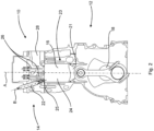
- Figures 1 to 4 show cross sectional views through a single cylinder assembly 23.
- the remaining cylinder assemblies (not shown) of the internal combustion engine 10 are substantially identical to the cylinder assembly 23 shown.
- the internal combustion engine 10 is a straight four cylinder engine, with four cylinders 16 arranged parallel to one another in a linear formation, and four piston assemblies 20 along a common crank shaft 18.
- the internal combustion engine has some other known cylinder arrangement, e.g. a straight six or V6.
- the internal combustion engine 10 is of the direct injection type described above.
- the cylinder assembly 23 includes a fuel injector 22 for injecting fuel directly into a combustion chamber 24 defined by the cylinder 16 and a piston 21 of the piston assembly 20.
- the fuel injector 22 is mounted to a fuel injection port 25.
- the fuel injector 22 has a longitudinal axis B. The fuel injector is supported within the cylinder head 14.
- the cylinder head 14 is formed within a cylinder head block 13.
- Each cylinder head 14 comprises two inlet ports 28 for air to be introduced into a combustion chamber 24 defined by the cylinder 16 and the piston assembly 20 and two outlet ports 33 for exhaust gases to be expelled. Through each cylinder head is arranged a spark plug 35 to ignite the hydrogen-air mixture.
- a single cylinder head block 13 is provided for all four cylinders heads 14 of the internal combustion engine 10, but in other embodiments a separate block may be provided for each cylinder head.
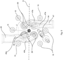
- Each cylinder head 14 is secured by six bolts 15 to the engine block 12, as best seen in Figure 5 .
- the bolts 15 are arranged symmetrically about a plane defined by an axis of rotation C of the crank shaft 18 and the axis A of the cylinder 16.
- the angle y between two of the adjacent bolts 15 is 46°, however, other angles in the range of 36° to 46° are also envisaged.
- So called "six bolt heads” are commonly found in compression ignition internal combustion engines - e.g. diesel engines - which operate at higher compression ratios and pressures than spark ignition engines - e.g. gasoline engines.
- Six bolts are typically required to maintain the integrity of the sealing between the engine block 12 and cylinder head 14 under these higher pressures, whereas gasoline engines typically utilise four bolts.
- the six bolts 15 restrict the space available to fit supply the combustion chamber with the required air, hydrogen fuel and spark, and allow exhaust gases to be outlet, whilst ensuring the engine runs efficiently and is compact.
- Compression ignition engines are commonly used in heavy duty applications where their high torque output at low rpm is beneficial for hauling of heavy loads, providing power to hydraulic pumps driving actuators of working arms of excavators or materials handling vehicles, or driving power take-offs to working implements such as agricultural machinery.
- Each inlet port 28 is selectably closable by a corresponding inlet valve 26, whilst each outlet port 33 is closable via a corresponding outlet valve 27 (see Figure 6 ).
- These inlet valves 26 and outlet valves 27 are part of a valve train.
- the inlet and outlet valves 26, 27 are located, when closed, in the corresponding port 28, 33 in a recessed position from an inner surface of the cylinder head 14.
- the inlet ports 28 have a larger diameter than that of the outlet ports 33 in order to optimise the airflow into the combustion chamber and achieve an optimised air-hydrogen mixture for lean combustion.
- inlet and outlet valves 26, 27 are arranged to be actuated parallel to axis A. This simplifies the construction of the valve train and cylinder head. In particular it may enable rocker arms (not shown) for the inlet and outlet valves to pivot about common axes, or at least parallel axes, potentially on a single rocker shaft (not shown) extending the length of the cylinders 16.
- the engine 10 further comprises inlet runners 45 arranged to feed into the inlet ports 28 of each cylinder head 14 from an inlet manifold (not shown).
- the inlet runners 45 bifurcate into a first section 45a and a second section 45b, the two sections 45a, 45b being connected to different inlet ports 28.
- the first and second sections 45a, 45b have non-equal lengths.
- the inlet runners 45 extend between two of the six bolts 15. In this way, the inlet runners 45 leave more space available to locate components such at the spark plug 35 and fuel injector 22.
- the inlet runners 45 are shaped such that air enters the combustion chamber 24 in such a direction such that swirl of air is generated about the combustion chamber 24, as indicated by arrow H and discussed in further detail below. The swirling motion is desirable for an efficient and low emission compression ignition combustion.
- outlet runners 47 connect the outlet ports 33 of each cylinder 16 with an exhaust manifold (not shown) and are bifurcated into a first section 47a and a second section 47b where they connect to each port and merge before connecting to the manifold, and extend between two of the six bolts 15 on the opposite side of the cylinder head 14 to the inlet ports 28.
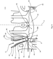
- the cylinder assembly 23 includes a fuel flow director 30.
- the fuel flow director 30 is situated in a fuel flow path D between an outlet 32 of the fuel injector 22 and the combustion chamber 24.
- the fuel injector 22 is oriented such that the injector longitudinal axis B extends at a first angle x in relation to the cylinder longitudinal axis A.
- the fuel flow director 30 directs fuel flow into the combustion chamber 24 at a second angle in relation to the cylinder longitudinal axis A, indicated in Figure 9 by arrow E.
- the second angle is different to the first angle x. That is, the angle at which fuel flow is directed into the combustion chamber 24 by the fuel flow director 30 is different to the angle of the longitudinal axis of the fuel injector 22.
- the fuel flow director 30 serves to change the direction of fuel flow between the fuel injector 22 and the combustion chamber 24.
- the fuel flow director 30 allows the direction of fuel injection into the combustion chamber 24 to be controlled, such that the angle of fuel flow E into the combustion chamber 24 is not solely dependent on the angle of orientation of the fuel injector 22.
- the fuel injector 22 is oriented at an angle of substantially 16° to the cylinder longitudinal axis A in a plane F within which the cylinder longitudinal axis A extends.
- the plane F is substantially perpendicular to the crank shaft axis G.
- the fuel injector is oriented at an angle of between 11° and 21° to the cylinder longitudinal axis A in the plane F.
- the fuel injector is oriented at some other non-zero angle.
- the fuel injector 22 is oriented at an angle of substantially 3° to the cylinder longitudinal axis A in a plane perpendicular to the plane F, and within which the cylinder longitudinal axis A extends. In alternative embodiments, the fuel injector is oriented at an angle of between 3° and 8° to the cylinder longitudinal axis A in the plane perpendicular to the plane F and within which the cylinder longitudinal axis A extends. In alternative embodiments, the fuel injector is oriented at some other non-zero angle.
- the direction E is substantially parallel to the cylinder longitudinal axis A, i.e. the second angle is substantially 0° in relation to the cylinder longitudinal axis A. It has been found that injecting fuel into the combustion chamber 24 at such an angle optimises fuel and air mixing.
- Circulation of fuel and air about the combustion chamber 24 is shown in Figures 10 and 11 .
- the swirling motion of air is further encouraged by offset chamfers 49 defined by the inlet ports 28, as shown in Figure 11 . That is, each inlet port 28 defines a chamfer 49 centred about a longitudinal axis that is offset from a longitudinal axis of the inlet port 28.
- the direction of fuel injection into the combustion chamber is indicated at arrow G.
- fuel is injected in a direction G substantially perpendicular to the direction of air swirl motion H.
- the difference in directions G and H results in greater disruption of the plume of the injected fuel, advantageously increasing homogeneity of the mixture.
- the second angle is within some other angle of the cylinder longitudinal axis A. In some embodiments, the second angle is within 5 degrees of the angle of the cylinder longitudinal axis A. In other embodiments, the second angle is within 10 degrees of the angle of the cylinder longitudinal axis A. In some embodiments, the second angle is within 15° of the angle of the cylinder longitudinal axis A. In other embodiments, the second angle is within 30° of the angle of the cylinder longitudinal axis A.
- the second angle is between 30° and 75° of the angle of the cylinder longitudinal axis A.
- the fuel flow director 30 has an aperture 34 defined by an internal face 36.
- the aperture 34 is at an outlet end 30a of the fuel flow director 30.
- the aperture 34 is on the fuel flow path D between the fuel injector 22 and the combustion chamber 24.
- the angle of the internal face 36 effects the direction of fuel flow into the combustion chamber 24. At least a portion of the internal face 36 is at an angle substantially parallel to the second angle, i.e. to the direction E. In this embodiment, the whole of the internal face 36 is at an angle substantially parallel to the second angle. In alternative embodiments, a portion or portions of the internal face 36 are substantially parallel to the second angle.
- Providing an aperture on the fuel flow path D having a side wall or internal face at a particular angle is a simple and effective means of directing fuel flow into the combustion chamber 24.
- the fuel flow director 30 has a single aperture 34. In alternative embodiments, the fuel flow director 30 has multiple such apertures 34 on the fuel flow path between the fuel injector 22 and the combustion chamber 24. For example, the fuel flow director has two or more apertures 34.
- the cylinder assembly 23 has a sleeve 38 that surrounds the fuel injector 22.
- the sleeve 38 extends over the outlet 32 of the fuel injector 22.
- the sleeve 38 of this embodiment includes the fuel flow director 30. That is, the sleeve 38 defines the aperture 34.
- the sleeve 38 has a first end 38a that extends over the fuel injector 22, and a second end 38b that defines the aperture 34.
- the sleeve second end 38a defines a chamber 40 beyond the fuel injector 22, i.e. between the fuel injector outlet 32 and the aperture 34 by which fuel leaves the sleeve 38.
- the chamber 40 aids the injection of fuel into the combustion chamber 24.
- the decrease in diameter between the chamber 40 walls and the aperture 34 leads to an acceleration of fuel as it leaves the fuel injector 22 and enters the combustion chamber 24, improving mixing of fuel and air within the combustion chamber 24.
- the smaller the cross-sectional area of the aperture 34 the greater the risk of fuel disadvantageously remaining within the chamber 40.
- the chamber 40 has a volume of 391mm 3 .
- the cross-sectional area of the aperture 34 is substantially 22.4mm 2 , so that the chamber volume to cross-sectional area ratio is substantially 17.5.
- Such a ratio has been found to provide optimal conditions for the injection of fuel into the combustion chamber 24, in particular when combined with the angle of the internal face 36.
- the chamber volume to cross-sectional area ratio is in the range of 16 to 21. In alternative embodiments, the chamber volume to cross-sectional area ratio is in the range of 17 to 19.
- a ratio in this range, in combination with the angle of the internal face 36, has been found to provide optimum introduction of fuel into the combustion chamber 24.
- the fuel injector 22 has a nozzle portion 22a and a wider body portion 22b.
- the nozzle portion 22a is at an outlet end of the fuel injector 22, proximal the combustion chamber 24.
- the sleeve 38 extends over the nozzle portion 22a, and does not extend over the wider body portion 22b.
- the cylinder assembly of this embodiment has a head adapter 42 for locating the fuel injector 22 with respect to the cylinder head 14.
- the sleeve 38 includes the head adapter 42, i.e. the head adapter 42 is integral to the sleeve 38.
- the head adapter 42 includes a lip 44 that abuts a shoulder 46 defined by the cylinder head 14 such that movement of the fuel injector 22 towards the combustion chamber 24 is inhibited.
- the sleeve 38 has a seal or seals 48 between the sleeve 38 and the cylinder head 14.
- the seal 48 is in this embodiment in the form of an O ring.
- the sleeve 38 has a further seal 50 in the form of an O ring, between the fuel injector 22 and the sleeve 38.
- the seal 50 prevents fuel escaping the chamber 40 other than through the aperture 34 to the combustion chamber 24.
- the fuel injector 22 and the sleeve 38 are shown in further detail in Figure 8 .
- the cylinder assembly 23 has a sleeve location arrangement 52.
- the sleeve location arrangement 52 prevents or at least inhibits the rotation of the sleeve 38 about the fuel injector longitudinal axis B.
- the sleeve location arrangement 52 has a location feature 54 defined by the sleeve and a corresponding location feature defined by the cylinder head 14 (not shown in this embodiment; shown in the embodiment of Figures 12 and 13 , described below).
- the location feature 54 defined by the sleeve 38 is in the form of a projection 54.
- the location feature defined by the cylinder head 14 is in the form of a bore for receiving the projection 54.
- the bore extends along the longitudinal axis B, such that the sleeve 38 can be fitted to the cylinder head 14 along the longitudinal axis B.
- the bore is drilled in a shape corresponding to that of the projection 54, in order to receive the projection 54.
- the sleeve location arrangement comprises some other suitable arrangement.
- the location feature defined by the sleeve is a recess, and the corresponding location feature defined by the cylinder head is in the form of a projection to be received in the recess.
- the piston 21 has a crown 60.
- the crown 60 defines an asymmetric depression 62.
- the asymmetric depression 62 further promotes mixing of fuel and air within the combustion chamber 24.
- the depression 62 is asymmetric within the plane F.
- the depression 62 has a crown low point 64, i.e. the point of the crown 60 furthest from the cylinder head 14.
- the crown low point 64 is offset from the cylinder longitudinal axis A within the plane F.
- the fuel injector 22 is offset from the cylinder longitudinal axis A in a first radial direction I.
- the crown low point 64 is offset from the cylinder longitudinal axis A in the first radial direction I. That is, the crown low point 64 is offset from the axis A in a direction towards the fuel injector 22. It has been found that the arrangement of the asymmetric depression 62 being offset with a low point 64 towards the fuel injector 22, in combination with direction of fuel flow in a direction substantially parallel to the cylinder longitudinal axis A, optimises mixing of fuel and air in a combustion chamber 24.
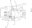
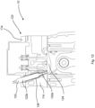
- FIG. 12 A second embodiment is shown in Figures 12 and 13 .
- similar parts are denoted by the same reference numerals to the first embodiment, but with the prefix "1". Only parts which differ from the first embodiment are discussed in detail.
- the sleeve 138 extends at least partway over the body portion 122b of the fuel injector 122 as well as over the nozzle portion 122a.
- the sleeve 138 serves to locate the fuel injector 122 in within the cylinder head 114.
- the cylinder assembly 123 includes a collar 166 for retention of the sleeve 138 and the fuel injector 122 within the cylinder head 114.
- the collar 166 of this embodiment has an outer threaded surface 168 for engagement with a corresponding threaded surface 170 of the cylinder head 114.
- the collar 166 defines a slot 172 for engagement with a tool (not shown) for the application of torque, in order to fit the collar 166 in the cylinder head 114.
- the slot 172 is milled. In an alternative embodiment, some other suitable machining method is used.
- the collar 166 extends beyond the cylinder head 114.
- a rocker cover 174 fitted to the cylinder head 114 defines a recess 176 into which the collar 166 extends.
- the recess 176 is shaped to allow vertical fitting of the rocker cover 174 to the cylinder head 114, to improve efficiency of assembly.
- the collar 166 serves to clamp the sleeve 138 in place and orient the sleeve 138 in a radial direction.
- the cylinder assembly 114 has a sleeve location arrangement 152 to prevent or at least inhibit the rotation of the sleeve 138 about the fuel injector longitudinal axis B.
- the location arrangement 152 is in the form of a projection (not shown) that extends into a corresponding bore 156.
- FIG. 14 A third embodiment is shown in Figure 14 .
- similar parts are denoted by the same reference numerals to the first embodiment, but with the prefix "2". Only parts which differ from the first embodiment are discussed in detail.
- the fuel flow director 230 is integral to the cylinder head 214.
- the aperture 234 is defined by the cylinder head 214. That is, the aperture 234 is machined into the cylinder head 214.
- a chamber 240 is defined by the cylinder head 214 between the fuel injector outlet 232 and the aperture 234.
- the fuel flow direction 230 being integral to the cylinder head 214 reduces the number of components required whilst providing the advantage of directing fuel into the combustion chamber 224.
Landscapes
- Engineering & Computer Science (AREA)
- Chemical & Material Sciences (AREA)
- Combustion & Propulsion (AREA)
- Mechanical Engineering (AREA)
- General Engineering & Computer Science (AREA)
- Chemical Kinetics & Catalysis (AREA)
- General Chemical & Material Sciences (AREA)
- Oil, Petroleum & Natural Gas (AREA)
- Fuel-Injection Apparatus (AREA)
- Cylinder Crankcases Of Internal Combustion Engines (AREA)
Applications Claiming Priority (1)
| Application Number | Priority Date | Filing Date | Title |
|---|---|---|---|
| GB2113870.6A GB2611101B (en) | 2021-09-28 | 2021-09-28 | An internal combustion engine |
Publications (4)
| Publication Number | Publication Date |
|---|---|
| EP4155517A2 true EP4155517A2 (de) | 2023-03-29 |
| EP4155517A3 EP4155517A3 (de) | 2023-04-05 |
| EP4155517B1 EP4155517B1 (de) | 2026-01-28 |
| EP4155517C0 EP4155517C0 (de) | 2026-01-28 |
Family
ID=78399545
Family Applications (1)
| Application Number | Title | Priority Date | Filing Date |
|---|---|---|---|
| EP22197293.8A Active EP4155517B1 (de) | 2021-09-28 | 2022-09-23 | Brennkraftmaschine |
Country Status (7)
| Country | Link |
|---|---|
| US (2) | US11713735B2 (de) |
| EP (1) | EP4155517B1 (de) |
| AU (1) | AU2022241461A1 (de) |
| BR (1) | BR102022019607A2 (de) |
| CA (1) | CA3175881A1 (de) |
| DE (1) | DE202022003367U1 (de) |
| GB (1) | GB2611101B (de) |
Cited By (1)
| Publication number | Priority date | Publication date | Assignee | Title |
|---|---|---|---|---|
| WO2024013632A1 (en) * | 2022-07-14 | 2024-01-18 | Punch Hydrocells S.R.L. | Internal combustion engine with hydrogen direct injection |
Families Citing this family (2)
| Publication number | Priority date | Publication date | Assignee | Title |
|---|---|---|---|---|
| CN116658294B (zh) * | 2023-06-21 | 2025-08-26 | 重庆长安汽车股份有限公司 | 一种适用于氢燃料发动机的超稀薄燃烧系统、分区燃烧控制方法及车辆 |
| US12540593B2 (en) | 2024-03-12 | 2026-02-03 | Caterpillar Inc. | Fuel injector assembly having sleeve with flow-directing cap and engine system using same |
Citations (1)
| Publication number | Priority date | Publication date | Assignee | Title |
|---|---|---|---|---|
| EP1931872B1 (de) * | 2005-09-28 | 2015-10-14 | Robert Bosch Gmbh | Ventil zum steuern eines fluids |
Family Cites Families (13)
| Publication number | Priority date | Publication date | Assignee | Title |
|---|---|---|---|---|
| GB470404A (en) * | 1936-02-13 | 1937-08-13 | Harry Ralph Ricardo | Improvements in or relating to internal combustion engines employing liquid fuel injection and compression ignition |
| US3062198A (en) * | 1961-11-17 | 1962-11-06 | Nickles Machine Corp | Gas engine fuel injection |
| DE1259634B (de) * | 1963-05-17 | 1968-01-25 | Hans List Dipl Ing Dr Techn | Gas-Ottomotor |
| US5293851A (en) * | 1992-04-16 | 1994-03-15 | Cooper Industries, Inc. | Combustion system for gas engine other than dual fuel engine |
| GB9821052D0 (en) * | 1998-09-28 | 1998-11-18 | Ricardo Consulting Eng | Direct injection gasoline engines |
| DE602005022061D1 (de) * | 2004-04-20 | 2010-08-12 | David Lange | System und verfahren zum betreiben eines verbrennuerkömmlichen fossilen brennstoffen |
| US7789047B2 (en) * | 2005-05-24 | 2010-09-07 | Toyota Jidosha Kabushiki Kaisha | Hydrogen-fueled internal combustion engine |
| US7270107B2 (en) * | 2006-01-20 | 2007-09-18 | Cameron International Corporation | Bolted pre-combustion chamber |
| US20080006713A1 (en) * | 2006-07-06 | 2008-01-10 | Parish James R | Fuel injector having an internally mounted cross-flow nozzle for enhanced compressed natural gas jet spray |
| US20080041343A1 (en) * | 2006-07-06 | 2008-02-21 | Parish James R Jr | Fuel injection system with cross-flow nozzle for enhanced compressed natural gas jet spray |
| DE102007040910A1 (de) * | 2007-08-30 | 2009-03-05 | Bayerische Motoren Werke Aktiengesellschaft | Kraftstoffeinbringungseinrichtung und Verfahren zum Betreiben derselben |
| WO2009114327A1 (en) * | 2008-03-12 | 2009-09-17 | Cameron International Corporation | Internal combustion engine with shrouded injection valve and precombustion chamber system |
| AT13172U1 (de) * | 2011-12-28 | 2013-07-15 | Ge Jenbacher Gmbh & Co Ohg | Vorkammersystem für eine Brennkraftmaschine |
-
2021
- 2021-09-28 GB GB2113870.6A patent/GB2611101B/en active Active
-
2022
- 2022-09-21 CA CA3175881A patent/CA3175881A1/en active Pending
- 2022-09-23 DE DE202022003367.2U patent/DE202022003367U1/de active Active
- 2022-09-23 EP EP22197293.8A patent/EP4155517B1/de active Active
- 2022-09-26 AU AU2022241461A patent/AU2022241461A1/en active Pending
- 2022-09-28 BR BR102022019607-9A patent/BR102022019607A2/pt unknown
- 2022-09-28 US US17/955,518 patent/US11713735B2/en active Active
-
2023
- 2023-06-14 US US18/210,071 patent/US12092056B2/en active Active
Patent Citations (1)
| Publication number | Priority date | Publication date | Assignee | Title |
|---|---|---|---|---|
| EP1931872B1 (de) * | 2005-09-28 | 2015-10-14 | Robert Bosch Gmbh | Ventil zum steuern eines fluids |
Cited By (1)
| Publication number | Priority date | Publication date | Assignee | Title |
|---|---|---|---|---|
| WO2024013632A1 (en) * | 2022-07-14 | 2024-01-18 | Punch Hydrocells S.R.L. | Internal combustion engine with hydrogen direct injection |
Also Published As
| Publication number | Publication date |
|---|---|
| US12092056B2 (en) | 2024-09-17 |
| US20230095893A1 (en) | 2023-03-30 |
| CA3175881A1 (en) | 2023-03-28 |
| US20230323842A1 (en) | 2023-10-12 |
| EP4155517B1 (de) | 2026-01-28 |
| GB2611101B (en) | 2026-03-25 |
| US11713735B2 (en) | 2023-08-01 |
| EP4155517A3 (de) | 2023-04-05 |
| AU2022241461A1 (en) | 2023-04-13 |
| GB2611101A (en) | 2023-03-29 |
| GB202113870D0 (en) | 2021-11-10 |
| EP4155517C0 (de) | 2026-01-28 |
| DE202022003367U1 (de) | 2026-04-30 |
| BR102022019607A2 (pt) | 2023-04-11 |
Similar Documents
| Publication | Publication Date | Title |
|---|---|---|
| US12092056B2 (en) | Internal combustion engine | |
| KR102156098B1 (ko) | 내연기관의 예연소실 및 그 작동 방법 | |
| CN105525982B (zh) | 用于内燃发动机的预燃室组件 | |
| US6644268B2 (en) | Method for the injection of fuel | |
| KR100336326B1 (ko) | 디젤형의왕복동피스톤내연기관 | |
| JP2017512277A (ja) | 内燃エンジン用の気体燃料燃焼装置 | |
| CN104295398A (zh) | 活塞的燃烧碗 | |
| US6035823A (en) | Spark-ignition type engine | |
| EP1151191B1 (de) | Vorrichtung für brennkraftmaschinen | |
| US12385446B2 (en) | Internal combustion engine with spark plug and prechamber spark plug | |
| EP0879943A3 (de) | Direkteinspritzbrennkraftmaschine mit Zündvorrichtung | |
| US20250052213A1 (en) | A nozzle cap, a fuel gas injection and a hydrogen internal combustion engine | |
| EP1111218A2 (de) | Luftbewegungssteuerklappe im oberen Einlasskrümmer | |
| US6170455B1 (en) | Internal combustion engine | |
| CN117927365A (zh) | 一种内燃发动机 | |
| US4693218A (en) | Internal combustion engine | |
| US20020017272A1 (en) | Internal combustion engine | |
| EP4448946B1 (de) | Kraftstoffeinspritzanordnung und wasserstoffverbrennungsmotor | |
| EP4295021B1 (de) | Vorkammeranordnung, zylinderkopf und kolbenmotor | |
| JP7854559B1 (ja) | 大型ターボ過給式2ストロークユニフロー掃気内燃機関のシリンダ内に燃料を噴射するための燃料弁、及びそのような燃料弁を備えた機関 | |
| JP7726251B2 (ja) | 内燃機関 | |
| US12044160B2 (en) | Pre-chamber for an internal combustion engine and combustion engine | |
| WO2021066708A1 (en) | Compression ignition engine with improved fuel distribution and vehicle comprising the engine | |
| US20250059940A1 (en) | A fuel gas injection arrangement and a hydrogen internal combustion engine | |
| US20250116241A1 (en) | Cylinder head offset chamfer design |
Legal Events
| Date | Code | Title | Description |
|---|---|---|---|
| PUAI | Public reference made under article 153(3) epc to a published international application that has entered the european phase |
Free format text: ORIGINAL CODE: 0009012 |
|
| STAA | Information on the status of an ep patent application or granted ep patent |
Free format text: STATUS: REQUEST FOR EXAMINATION WAS MADE |
|
| PUAL | Search report despatched |
Free format text: ORIGINAL CODE: 0009013 |
|
| 17P | Request for examination filed |
Effective date: 20220926 |
|
| AK | Designated contracting states |
Kind code of ref document: A2 Designated state(s): AL AT BE BG CH CY CZ DE DK EE ES FI FR GB GR HR HU IE IS IT LI LT LU LV MC MK MT NL NO PL PT RO RS SE SI SK SM TR |
|
| AK | Designated contracting states |
Kind code of ref document: A3 Designated state(s): AL AT BE BG CH CY CZ DE DK EE ES FI FR GB GR HR HU IE IS IT LI LT LU LV MC MK MT NL NO PL PT RO RS SE SI SK SM TR |
|
| RIC1 | Information provided on ipc code assigned before grant |
Ipc: F02B 43/10 20060101ALI20230302BHEP Ipc: F02M 39/00 20060101ALI20230302BHEP Ipc: F02B 31/04 20060101ALI20230302BHEP Ipc: F02B 29/02 20060101AFI20230302BHEP |
|
| STAA | Information on the status of an ep patent application or granted ep patent |
Free format text: STATUS: EXAMINATION IS IN PROGRESS |
|
| 17Q | First examination report despatched |
Effective date: 20240702 |
|
| P01 | Opt-out of the competence of the unified patent court (upc) registered |
Free format text: CASE NUMBER: APP_46/2025 Effective date: 20250102 |
|
| REG | Reference to a national code |
Ref country code: DE Ref legal event code: R079 Ref document number: 602022029171 Country of ref document: DE Free format text: PREVIOUS MAIN CLASS: F02B0029020000 Ipc: F02M0061140000 |
|
| RIC1 | Information provided on ipc code assigned before grant |
Ipc: F02M 61/14 20060101AFI20250714BHEP Ipc: F02B 29/02 20060101ALI20250714BHEP Ipc: F02B 31/04 20060101ALI20250714BHEP Ipc: F02B 43/10 20060101ALI20250714BHEP |
|
| GRAP | Despatch of communication of intention to grant a patent |
Free format text: ORIGINAL CODE: EPIDOSNIGR1 |
|
| STAA | Information on the status of an ep patent application or granted ep patent |
Free format text: STATUS: GRANT OF PATENT IS INTENDED |
|
| INTG | Intention to grant announced |
Effective date: 20250826 |
|
| GRAS | Grant fee paid |
Free format text: ORIGINAL CODE: EPIDOSNIGR3 |
|
| GRAA | (expected) grant |
Free format text: ORIGINAL CODE: 0009210 |
|
| STAA | Information on the status of an ep patent application or granted ep patent |
Free format text: STATUS: THE PATENT HAS BEEN GRANTED |
|
| AK | Designated contracting states |
Kind code of ref document: B1 Designated state(s): AL AT BE BG CH CY CZ DE DK EE ES FI FR GB GR HR HU IE IS IT LI LT LU LV MC MK MT NL NO PL PT RO RS SE SI SK SM TR |
|
| REG | Reference to a national code |
Ref country code: CH Ref legal event code: F10 Free format text: ST27 STATUS EVENT CODE: U-0-0-F10-F00 (AS PROVIDED BY THE NATIONAL OFFICE) Effective date: 20260128 Ref country code: GB Ref legal event code: FG4D |
|
| REG | Reference to a national code |
Ref country code: DE Ref legal event code: R096 Ref document number: 602022029171 Country of ref document: DE |
|
| REG | Reference to a national code |
Ref country code: IE Ref legal event code: FG4D |
|
| U01 | Request for unitary effect filed |
Effective date: 20260225 |
|
| U07 | Unitary effect registered |
Designated state(s): AT BE BG DE DK EE FI FR IT LT LU LV MT NL PT RO SE SI Effective date: 20260303 |
|
| P04 | Withdrawal of opt-out of the competence of the unified patent court (upc) registered |
Free format text: CASE NUMBER: APP_46_1/2025 Effective date: 20260303 |