EP4155647A1 - Wärmetauscher mit mindestens einer wärmeaustauschstruktur mit einer gestreiften oberfläche - Google Patents
Wärmetauscher mit mindestens einer wärmeaustauschstruktur mit einer gestreiften oberfläche Download PDFInfo
- Publication number
- EP4155647A1 EP4155647A1 EP22196629.4A EP22196629A EP4155647A1 EP 4155647 A1 EP4155647 A1 EP 4155647A1 EP 22196629 A EP22196629 A EP 22196629A EP 4155647 A1 EP4155647 A1 EP 4155647A1
- Authority
- EP
- European Patent Office
- Prior art keywords
- heat exchange
- fins
- longitudinal direction
- passages
- exchanger
- Prior art date
- Legal status (The legal status is an assumption and is not a legal conclusion. Google has not performed a legal analysis and makes no representation as to the accuracy of the status listed.)
- Granted
Links
Images


Classifications
-
- F—MECHANICAL ENGINEERING; LIGHTING; HEATING; WEAPONS; BLASTING
- F28—HEAT EXCHANGE IN GENERAL
- F28D—HEAT-EXCHANGE APPARATUS, NOT PROVIDED FOR IN ANOTHER SUBCLASS, IN WHICH THE HEAT-EXCHANGE MEDIA DO NOT COME INTO DIRECT CONTACT
- F28D9/00—Heat-exchange apparatus having stationary plate-like or laminated conduit assemblies for both heat-exchange media, the media being in contact with different sides of a conduit wall
- F28D9/0062—Heat-exchange apparatus having stationary plate-like or laminated conduit assemblies for both heat-exchange media, the media being in contact with different sides of a conduit wall the conduits for one heat-exchange medium being formed by spaced plates with inserted elements
-
- F—MECHANICAL ENGINEERING; LIGHTING; HEATING; WEAPONS; BLASTING
- F28—HEAT EXCHANGE IN GENERAL
- F28F—DETAILS OF HEAT-EXCHANGE AND HEAT-TRANSFER APPARATUS, OF GENERAL APPLICATION
- F28F13/00—Arrangements for modifying heat-transfer, e.g. increasing, decreasing
- F28F13/18—Arrangements for modifying heat-transfer, e.g. increasing, decreasing by applying coatings, e.g. radiation-absorbing, radiation-reflecting; by surface treatment, e.g. polishing
- F28F13/185—Heat-exchange surfaces provided with microstructures or with porous coatings
-
- F—MECHANICAL ENGINEERING; LIGHTING; HEATING; WEAPONS; BLASTING
- F28—HEAT EXCHANGE IN GENERAL
- F28F—DETAILS OF HEAT-EXCHANGE AND HEAT-TRANSFER APPARATUS, OF GENERAL APPLICATION
- F28F3/00—Plate-like or laminated elements; Assemblies of plate-like or laminated elements
- F28F3/02—Elements or assemblies thereof with means for increasing heat-transfer area, e.g. with fins, with recesses, with corrugations
- F28F3/025—Elements or assemblies thereof with means for increasing heat-transfer area, e.g. with fins, with recesses, with corrugations the means being corrugated, plate-like elements
-
- F—MECHANICAL ENGINEERING; LIGHTING; HEATING; WEAPONS; BLASTING
- F28—HEAT EXCHANGE IN GENERAL
- F28D—HEAT-EXCHANGE APPARATUS, NOT PROVIDED FOR IN ANOTHER SUBCLASS, IN WHICH THE HEAT-EXCHANGE MEDIA DO NOT COME INTO DIRECT CONTACT
- F28D21/00—Heat-exchange apparatus not covered by any of the groups F28D1/00 - F28D20/00
- F28D2021/0019—Other heat exchangers for particular applications; Heat exchange systems not otherwise provided for
- F28D2021/0033—Other heat exchangers for particular applications; Heat exchange systems not otherwise provided for for cryogenic applications
-
- F—MECHANICAL ENGINEERING; LIGHTING; HEATING; WEAPONS; BLASTING
- F28—HEAT EXCHANGE IN GENERAL
- F28D—HEAT-EXCHANGE APPARATUS, NOT PROVIDED FOR IN ANOTHER SUBCLASS, IN WHICH THE HEAT-EXCHANGE MEDIA DO NOT COME INTO DIRECT CONTACT
- F28D9/00—Heat-exchange apparatus having stationary plate-like or laminated conduit assemblies for both heat-exchange media, the media being in contact with different sides of a conduit wall
- F28D9/0062—Heat-exchange apparatus having stationary plate-like or laminated conduit assemblies for both heat-exchange media, the media being in contact with different sides of a conduit wall the conduits for one heat-exchange medium being formed by spaced plates with inserted elements
- F28D9/0068—Heat-exchange apparatus having stationary plate-like or laminated conduit assemblies for both heat-exchange media, the media being in contact with different sides of a conduit wall the conduits for one heat-exchange medium being formed by spaced plates with inserted elements with means for changing flow direction of one heat exchange medium, e.g. using deflecting zones
-
- F—MECHANICAL ENGINEERING; LIGHTING; HEATING; WEAPONS; BLASTING
- F28—HEAT EXCHANGE IN GENERAL
- F28F—DETAILS OF HEAT-EXCHANGE AND HEAT-TRANSFER APPARATUS, OF GENERAL APPLICATION
- F28F2215/00—Fins
- F28F2215/10—Secondary fins, e.g. projections or recesses on main fins
Definitions
- the present invention relates to a heat exchanger of the plate and fin type comprising at least at least one heat exchange structure with a ribbed surface.
- the present invention finds particular application in the field of cryogenic gas separation, in particular cryogenic air separation (known by the acronym "ASU" for air separation unit) used for the production of oxygen gas under pressure.
- cryogenic air separation known by the acronym "ASU” for air separation unit
- the present invention can be applied to a heat exchanger which vaporizes a refrigerant fluid, for example liquid oxygen, by heat exchange with a calorigenic fluid, for example gaseous nitrogen.
- the heat exchanger is located in the bottom of a distillation column, it can constitute a vaporizer-condenser operating as a thermosiphon for which the exchanger is immersed in a bath of liquid oxygen descending the column or a vaporizer operating in falling film vaporization fed directly by the liquid falling from the column and/or by a recirculation pump.
- the present invention can also be applied to a heat exchanger which vaporizes at least one flow of liquid-gas mixture, in particular a flow of mixture with several constituents, for example a mixture of hydrocarbons, by heat exchange with at least another fluid, for example natural gas.
- the present invention can also find application in the field of hydrogen liquefaction.
- the invention can be applied to a heat exchanger, in particular a catalytic exchanger, in which a flow of gaseous hydrogen is cooled, or even liquefied in whole or in part, by heat exchange with a flow of refrigerant as well as the cooling and/or liquefaction process implementing said exchanger.
- exchangers The technology commonly used for an exchanger is that of aluminum exchangers with plates and brazed fins or waves, which make it possible to obtain very compact devices offering a large exchange surface.
- These exchangers comprise separator plates, a stack of passages for the different fluids to be placed in a heat exchange relationship.
- Heat exchange structures generally corrugated structures or waves formed by a succession of fins or wave legs, are inserted between the plates, delimiting in the passages of the channels in which the fluids flow and forming surfaces additional heat exchange.
- part of the apparatus is devoted to the distribution of the liquid refrigerant in the vaporization passages.
- the liquid passes through holes ensuring a primary distribution of the liquid over the entire width of the passage.
- the liquid thus pre-distributed then flows through waves with a horizontal generator which ensures a finer distribution called secondary in order to distribute the liquid between the channels formed by heat exchange waves with a horizontal generator arranged downstream.
- the liquid thus approaches these structures by streaming as evenly as possible over all the walls of the passage which is assigned to it, that is to say by forming on these walls a continuous descending film.
- the gaseous refrigerant enters the exchanger through a supply box and then flows downwards along the condensation passages.
- the circulating fluid gradually gives up heat to the refrigerant in the adjacent passages, so that the refrigerant vaporizes and the circulating fluid condenses. Consequently, a film of liquid circulating fluid is established on the surface of the exchange structures lining the condensation passages and flows downwards. The flow is said to be in trickling film.
- the liquid oxygen enters through the bottom of the exchanger body into the vaporization passages and flows there in an upward direction, the gaseous nitrogen entering from the top into the condensation passages and flowing downwards in a dripping film.
- the performance of an exchanger is linked to the heat exchange coefficient of the heat exchange structures in contact with the fluids.
- the heat exchange coefficient of a structure depends in particular on the nature of the material constituting it, the porosity of this material, its surface condition and the fluid flow regime.
- the resistance to heat transfer is substantially proportional to the thickness of the liquid film. According to Nusselt's theory, the resistance to heat transfer varies in power 1/3 of the flow, which leads to a rapid increase in resistance at the locations of the heat exchange structures where the fluid condenses. This results in a reduction in the heat transfer capacity between the fluid to be condensed and the heat exchange structure.
- the resistance to heat transfer in trickling film vaporization is substantially proportional to the thickness of the liquid film. It is therefore advantageous to drain the maximum liquid flow rate falling towards a reduced part of the exchange surface in order to minimize the thickness of the liquid film on the other part of the exchange surface.
- corrugated heat exchange structure making it possible to regularly drain the liquid in the corners of the channels formed by the waves.
- the structure comprises perforations, slots or reliefs arranged on the height of the wave legs in order to dry out part of their surface.
- the object of the present invention is to solve all or part of the problems mentioned above, in particular to propose a heat exchanger of the plate and fin type in which the heat exchange coefficient of the heat exchange structures is increased.
- the solution according to the invention is then a heat exchanger of the plate and fin type for placing in heat exchange relationship at least one refrigerant fluid and one circulating fluid, said exchanger comprising a plurality of plates arranged parallel to each other and to a longitudinal direction so as to define between said plates a plurality of passages, at least one passage being formed between two adjacent plates and comprising at least one heat exchange structure provided with at least one series of fins, said fins extending parallel to the longitudinal direction and succeeding each other in a lateral direction which is orthogonal to the longitudinal direction and parallel to the plates, so that the fins define within the passage channels adapted for the flow of the refrigerant fluid or of the circulating fluid parallel to the longitudinal direction, characterized in that at least one fin has on at least part of its surface a surface texturing under the form of streaks arranged parallel to the longitudinal direction.
- the exchanger according to the invention may comprise one or more of the technical characteristics given below.
- the ridges are arranged periodically with a period between 0.1 and 2 mm, preferably between 0.4 and 1 mm.
- the ridges are straight and continuous.
- the ridges are arranged such that a ridge is separated from an adjacent ridge by a ridge and has an amplitude, defined as the maximum distance between the bottom of a ridge and the top of a ridge measured orthogonally to the surface of the fin, between 0.1 and 1 mm, preferably between 0.3 and 0.6 mm.
- the surface texturing is configured so that the heat exchange structure has a heat exchange coefficient increased by a multiplying factor between 2 and 7, preferably between 2 and 5, relative to the heat exchange coefficient d an identical structure free of surface texturing.
- Said at least one fin has a first surface and a second opposite surface, each forming a side wall of a respective channel, one and/or the other of said first and second surface having a surface texturing on its whole or its almost all.
- the heat exchange structure is in the form of a corrugated product comprising at least one corrugation with wave crests and wave bases arranged against the plates and alternately connected by fins, said fins thus forming legs of wave and the lateral direction defining a direction of undulation of the heat exchange structure.
- Said wave crests and/or said wave bases have surface texturing over at least part of their surface.
- the exchanger comprises an inlet manifold configured to distribute the refrigerant or the circulating fluid in the passages and an outlet manifold configured to evacuate the refrigerant or the circulating fluid from the passages, the inlet manifold being arranged at a level higher than the level of the outlet manifold in the longitudinal direction, so that the refrigerant or the circulating fluid flows in the passages in a downward direction opposite to the direction of the longitudinal direction.
- the invention relates to a heat exchange structure for a heat exchanger of the plate and fin type, said structure being in the form of a corrugated product comprising a succession of fins alternately connected by wave tops and wave bases, characterized in that said corrugated product is formed from a flat product comprising two opposite faces and at least one surface texturing in the form of a porous structure or reliefs formed on a surface of the product flat, only one of said opposite faces having on all or almost all of said surface texturing.
- the invention relates to an installation for the separation of air by distillation comprising at least one heat exchanger according to the invention, the installation comprising supply means for distributing in the passages of the exchanger the liquid oxygen as refrigerant and nitrogen gas as circulating fluid.
- a heat exchanger As seen on [ Fig. 1 ], a heat exchanger according to the invention comprises a set of plates 2 arranged parallel to each other with spacing and thus forming several series of passages 17, 18 of parallelepiped and flat shape for the flow of at least one refrigerant and at least one circulating fluid to be placed in indirect heat exchange relationship via the plates 2.
- the plates 2 follow one another in a stacking direction y.
- FIG.1 illustrates one embodiment of a heat exchanger suitable for use in a double column type air distillation plant.
- a heat exchange takes place between liquid oxygen as refrigerant and gaseous nitrogen as circulating fluid.
- the exchanger comprises a sealed casing 40 containing a body formed from a set of rectangular plates 2, generally formed from aluminum, which are stacked parallel to each other and parallel to a longitudinal direction z.
- the plates 4 thus define a plurality of vaporization passages 17 intended for the flow of oxygen and of condensation passages 18 intended for the flow of nitrogen.
- the fluids flow parallel to the longitudinal direction z.
- the passages 17, 18 each contain heat exchange structures 1 comprising in this example corrugated aluminum sheets, also exchange waves. These waves can be perforated or not.
- These exchange structures 1 are preferably of the vertical generatrix type, or so-called “easyway” arrangement.
- the corrugated exchange structures 1 have, in operation, an overall corrugation direction which is orthogonal to the longitudinal direction z and parallel to the lateral direction x on [ Fig.1 ].
- the exchange structures 1 can be extended respectively by so-called distribution waves 20, 24 serving to distribute the fluids in the respective passages.
- distribution waves 20, 24 serving to distribute the fluids in the respective passages.
- the passages 17 and 18 are closed respectively by horizontal bars 28 and 21.
- the space located above the plates 2 contains a bath of liquid oxygen 15.
- the liquid oxygen from the bath 15 flows through orifices 29 drilled along the bars 28 ensuring a primary distribution of the liquid oxygen between all passages 17 for the oxygen and over the entire width of each passage 17, in the direction of the waves 24.
- the wave strips 24 are generally formed from non-perforated corrugated aluminum sheets of the type with a horizontal generatrix, or so-called “hardway” arrangement. In this case, the wavebands 24 have, in operation, an overall direction of undulation parallel to the longitudinal direction z.
- the nitrogen gas enters the exchanger through a supply box (not shown) and the distribution waves 20, then flows downwards along the passages 18.
- the plates 2 are spaced apart by sealing bars which do not completely block the passages 17, 18 but leave inlet and outlet openings.
- the inlets and outlets of each passage serving for the circulation of the same fluid are joined by manifolds serving for the introduction and the evacuation of the fluid.
- the longitudinal direction z is vertical when the exchanger is in operation.
- the refrigerants and calorigens generally flow vertically and in co-current, in the downward direction, that is to say opposite to the direction of the longitudinal direction z on [ Fig. 1 ].
- the exchanger comprises at least one inlet manifold configured to distribute the refrigerant or the circulating fluid in the passages (17, 18) of the body and at least one outlet manifold configured to evacuate the refrigerant or the circulating fluid passages 17.18.
- the inlet manifold is arranged at a level higher than the level of the outlet manifold in the longitudinal direction z, so that the refrigerant or the circulating fluid flows in the passages 17, 18 in a downward direction opposite to the direction of the longitudinal direction z.
- such an arrangement is implemented for the refrigerant and for the circulating fluid.
- the exchanger according to the invention can be of the vaporizer-condenser type whose vaporization passages are supplied with liquid oxygen under low pressure (typically slightly above atmospheric pressure) collected at the bottom of a column.
- the oxygen is vaporized by medium pressure nitrogen condensation (typically 5 to 6 bar absolute) circulating in adjacent passages.
- the medium pressure nitrogen is most often withdrawn in the gaseous state at the top of a medium pressure air distillation column to which the low pressure column mentioned above is connected. After its passage and its at least partial condensation in the vaporizer-condenser, this nitrogen is returned to the medium-pressure column.
- all or part of the passages of the exchanger 1 are provided with at least one heat exchange structure 1 defining, within the passages, channels 4 for the circulation of the refrigerant or the fluid calorigenic and can take different forms.
- At least one passage 17 formed between two adjacent plates 2 comprises a heat exchange structure 1 provided with at least one series of fins 123 extending parallel to the longitudinal direction z and succeeding one another in the lateral direction x which is orthogonal to the longitudinal direction z and parallel to the plates 2.
- the fluid circulating in the passage 17 is in indirect heat exchange relation via a plate 2 which forms a primary exchange surface.
- the fins 123 form secondary exchange surfaces which make it possible to intensify the exchanges of heat between the fluids, as well as to stiffen the passages of the exchange by playing the role of spacers.
- the exchange structures 1 of the exchanger are connected by brazing to the plates 2.
- Structure 1 can have a wavy shape, as shown in [ Fig. 2 ], and comprise wave legs 123 alternately connected by wave tops 121 and wave bases 122. In this case, the wave legs which connect the successive tops and bases of the wave.
- the structure 1 can also take other particular shapes defined according to the desired fluid flow characteristics. More generally, the term “fins” covers blades or other secondary exchange surfaces thermal, which extend between the primary heat exchange surfaces, that is to say the plates of the exchanger, in the passages of the exchanger.
- the channels 4 defined between each pair of consecutive fins 123 have a cross section of generally rectangular shape, the fins extending generally parallel to the longitudinal direction z and parallel to the stacking direction y. It is also possible for the fins 123 to form an angle of inclination with the direction y. Note that in the case of channels formed between the wave legs of a corrugated structure, the fins 123 form the side walls of the channels, the upper walls of the channels being formed by wave crests 121 or a plate portion 2 according to the corrugation zone considered and the lower walls of the channels being formed by wave bases 121 or a plate portion 2 according to the corrugation zone considered.
- heat exchange structure 1 of the corrugated product type it is possible to use the different types of waves usually implemented in exchangers of the plate and fin type, namely straight waves, offset waves partial (of the "serrated” type in English), waves with waves or herringbones (of the "herringbone” type in English), perforated or not.
- the heat exchange structure 1 has a height h, corresponding substantially to the height of the passage in which it is arranged, of between 3 and 10 mm.
- the heat exchange structure 1 can have a thickness e of between 0.2 and 0.6 mm.
- the fins 123 follow one another periodically with a pitch p between two successive fins.
- the phenomenon of drainage of the liquid 5 flowing in the channels 4 of the vaporization or condensation passages takes place naturally by capillarity.
- the drainage capacity of the corners is relatively large because the radius r of the menisci varies in power 1/4 of the liquid flow.
- the channel 4 comprises relatively little liquid.
- the liquid is mainly located in the corners by capillarity but wets the entire surface.
- ridges furrows, or grooves, parallel to each other which mark a surface. It being understood that a surface texturing 23 according to the invention can just as easily be produced in the surfaces of the material constituting the exchange structures as it can be deposited there, that is to say result from an addition of additional material on structural surfaces. In particular, the ridges may result from removal of material from the surface of the structure.
- the grooves can be produced by laser machining, by mechanical machining and/or by chemical machining.
- the ridges of the texturing 23 make it possible to reduce the thickness of the liquid film on the surface of the fin 123, and consequently the resistance to heat transfer.
- the ridges consequently lead to an increase in the heat exchange efficiency of the structure.
- the arrangement of the grooves parallel to the longitudinal direction z that is to say with the same orientation as that of the channels 4, facilitates the flow of the liquid towards the bottom of the exchange structure 1.
- the streaks form hollows, or valleys, which have the function of draining the liquid by capillarity and locally reducing the thickness of the liquid on the areas of the fin located between the streaks, thus promoting heat transfer at the level of these areas. .
- [ Fig. 4 ] schematizes a heat exchange structure 1 made in the form of a corrugated product.
- the ribbed texturing 23 can be performed on a flat product 10 which is subsequently shaped. The production of the grooves is thus facilitated and their arrangement and dimensioning are controlled more precisely.
- Texturing 23 is formed on at least one of the two faces 10a, 10b of the flat product.
- the texturing is arranged on the two opposite faces 10a, 10b of the flat product, which makes it possible to maximize the surface of the walls of the channels 4, the heat transfer efficiency of which is increased.
- the streaks of the texturing zone 23 are rectilinear and continuous, that is to say formed in an uninterrupted manner.
- the fins 123 have the surface texturing 23 on their two opposite surfaces 123a, 123b, preferably on all or almost all of said surfaces 123a, 123b.
- the fins 123 between them delimit channels 4 whose side walls, formed by the two fins 123, have surfaces with improved heat exchange performance. It is in fact these zones of the channels 4 which have the main function of ensuring the exchange of heat, the upper and lower walls of the channels having the main function of ensuring the flow of the liquid parallel to the longitudinal direction z.
- almost all of a surface, a face or an element means a portion representing at least 90%, preferably at least 95%, of more preferably at least 98% of the area of this surface or face or of the total area of this element.
- At least one structure according to the invention is arranged in several passages, even all or almost all of the passages of the exchanger, in the passages for the circulating fluid and/or in the passages for the fluid refrigerant.
- the ridges extend vertically in operation.
- the wave crests 121 and/or the wave bases 122 also have two opposite surfaces, one oriented on the side of the adjacent plate 2 and the other on the side of the inside of the channel 4 delimited between the two fins 123 linked to the wave crest or to the wave base as the case may be.
- At least the wave base or wave top surface oriented towards the channel 4 has a texturing 23.
- the fins or wave legs 123 delimit between them a channel 4 whose bottom or top, formed by the surfaces of a wave base or a wave top have internal surfaces with improved heat transfer.
- the surfaces of the wave bases and/or of the wave crests have the surface texturing 23 on all or almost all of them. It is also possible for the wave base or wave top surfaces oriented towards an adjacent plate 2 to have a texturing 23. This facilitates the preparation of the surface of the exchange structure 1 since it is not necessary to differentiate areas with or without texturing.
- structure 1 is in the form of a single undulation straight wave. It should be noted that the structure 1 can be in the form of a partially offset wave, that is to say comprising a series of undulations which follow one another in the longitudinal direction z and are arranged offset from each other. relative to others in the lateral direction x. According to one possibility, the serration length, that is to say the length of a corrugation measured parallel to the longitudinal direction z, can be between 3 and 10 mm.
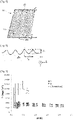
- FIG. 6 schematizes an example of texturing profile 23 in cross section in a plane orthogonal to the longitudinal direction z.
- the texturing is carried out on at least one surface portion of the material constituting the exchange structure 1.
- the stripes of texturing 23 are arranged periodically with a period L comprised between 0.1 and 2 mm, preferably comprised between 0.4 and 1 mm.
- the surface texturing is such that the ratio between the height h of the fin and the period L of the grooves is between 5 and 20, preferably between 5 and 10.
- Said period is in particular in line with the height of the fins or wave legs. Said period must also ensure good thermal performance: streaks that are too far apart only impact a portion of the heat exchange surface, because the liquid drainage effect only extends over a certain distance on both sides. away from the ridge, while ridges that are too close together do not drain the fluid effectively enough.
- the streaks must be manufacturable and economically viable.
- the ridges can be arranged so that a ridge is separated from an adjacent ridge by a ridge and has an amplitude A, defined as the maximum distance between the bottom of a ridge and the top of a ridge, measured orthogonally to the surface of the structure 1, between 0.1 and 1 mm and preferably between 0.3 mm and 0.6 mm.
- A defined as the maximum distance between the bottom of a ridge and the top of a ridge, measured orthogonally to the surface of the structure 1, between 0.1 and 1 mm and preferably between 0.3 mm and 0.6 mm.
- the preferential amplitude results from various factors: geometric adequacy with the shape of the exchange structures considered, the thermal performance and the constraints of manufacturing and shaping of the waves.
- the inventors of the present invention have demonstrated that it was advantageous, in terms of liquid drainage, for the ridges to have an amplitude of the same order of magnitude as the thickness of the film of condensate conventionally forming on a heat exchange structure without implementing the invention.
- film thicknesses ranging in particular from 50 to 300 ⁇ m could be observed. Making streaks with an amplitude of the same order of magnitude or greater makes it possible to effectively dry the tops of the streaks.
- period and amplitude values of the value streaks mean values averaged over the texturing surface considered, in particular over the surface of the fin comprising the texturing.
- the projected surface means the surface projected in a plane parallel to said surface.
- the surface texturing 23 is configured so that the heat exchange structure has a heat exchange coefficient increased by a multiplying factor between 2 and 7, preferably between 2 and 5, relative to the coefficient of heat exchange of an identical structure free of surface texturing 23.
- a heat exchange structure 1 according to the invention may have a heat exchange coefficient of between 5 and 30 kW/m2/K. It should be noted that by heat exchange coefficient, or heat transfer coefficient, is meant a coefficient quantifying the flow of energy passing through the heat exchange structure, per unit of surface, volume or length and for a given temperature difference. .
- the heat transfer coefficient between a fluid and a structure depends on intrinsic parameters, that is to say specific to the exchange structure itself, in particular the density of the wave forming the structure, the thickness of the wave, as well as extrinsic parameters, that is to say specific to the process implemented, in particular the flow rate of the fluids and the temperature difference between the fluids.
- the heat exchange coefficient can be determined using correlation methods known per se.
- the heat exchange coefficients of the heat exchange structure with and without texturing 23 are compared with an identical or almost identical method of measurement or theoretical determination, the specific conditions to the exchange process (ie extrinsic parameters) being identical or almost identical.
- texturing 23 was carried out on an initially flat and relatively smooth plate, the surface of the plate having an arithmetic roughness of 8 ⁇ m, 200 mm long and 100 mm wide.
- the streaks were formed using a mechanical tool.
- the streaks had an average period of 1 mm and an average amplitude A of 280 ⁇ m (area called C).
- the structure presented a developed surface increased by 25% compared to its projected surface.
- the structure was tested in condensation in a passage where nitrogen gas was introduced at atmospheric pressure (hot condensing fluid) in indirect heat exchange with liquid nitrogen at a lower pressure circulating in an adjacent passage (fluid boiling cold).
- the pressure of "cold” liquid nitrogen was controlled in order to vary its boiling temperature, and therefore the temperature difference between fluids (the "hot” gaseous nitrogen condensing at its condensation temperature at atmospheric pressure ).
- the surface heat flux was measured using two independent techniques, the results of which are identical to within 10%.
- the first technique local, consisted in measuring the transverse temperature gradient established in the plate separating the two fluids to deduce the surface heat flux (knowing the conductivity of the material). The measurement was carried out at different positions, the mean surface flux being calculated from these different measurements.
- the second technique global, consisted in measuring the flow of condensed nitrogen. To do this, the condensates flowing on the tested plate were collected, for a determined time, in a container graduated in volume in order to determine the volume flow rate, and therefore the heat flux used for condensation (assuming losses negligible thermals).
- FIG. 7 shows a comparison of the heat exchange coefficients obtained with the grooved exchange structure according to the invention and other exchange structures without grooves, all intrinsic characteristics being otherwise identical.
- the surface called A is a so-called raw flat surface, with an arithmetic roughness of 8 micrometers. This surface represents the current state of the art, being made of a material typically used for the manufacture of brazed plate and fin heat exchangers, typically aluminum or an aluminum alloy.
- Surface C is the ribbed surface according to the invention described above. We observe that the performance, in terms of heat exchange coefficient, is approximately three times greater than that of surface A.
- Curve B is illustrative: surface B presents the same data as surface A, but multiplied by a coefficient equal to the increase in developed surface generated by the grooves of surface C.
- the comparison of the results obtained with surface C and surface B demonstrates that the increase in performance is not solely due to the increase in developed surface but above all to the realization of the ridges parallel to the longitudinal direction, effectively channeling the liquid.
Landscapes
- Engineering & Computer Science (AREA)
- Physics & Mathematics (AREA)
- Thermal Sciences (AREA)
- Mechanical Engineering (AREA)
- General Engineering & Computer Science (AREA)
- Chemical & Material Sciences (AREA)
- Crystallography & Structural Chemistry (AREA)
- Heat-Exchange Devices With Radiators And Conduit Assemblies (AREA)
Applications Claiming Priority (1)
| Application Number | Priority Date | Filing Date | Title |
|---|---|---|---|
| FR2110123A FR3127561B1 (fr) | 2021-09-27 | 2021-09-27 | Echangeur comprenant au moins une structure d’échange thermique à surface striée |
Publications (2)
| Publication Number | Publication Date |
|---|---|
| EP4155647A1 true EP4155647A1 (de) | 2023-03-29 |
| EP4155647B1 EP4155647B1 (de) | 2024-08-21 |
Family
ID=79018500
Family Applications (1)
| Application Number | Title | Priority Date | Filing Date |
|---|---|---|---|
| EP22196629.4A Active EP4155647B1 (de) | 2021-09-27 | 2022-09-20 | Wärmetauscher mit mindestens einer wärmeaustauschstruktur mit einer gestreiften oberfläche |
Country Status (4)
| Country | Link |
|---|---|
| US (1) | US12196503B2 (de) |
| EP (1) | EP4155647B1 (de) |
| CN (1) | CN115876007A (de) |
| FR (1) | FR3127561B1 (de) |
Citations (6)
| Publication number | Priority date | Publication date | Assignee | Title |
|---|---|---|---|---|
| FR2834783A1 (fr) | 2002-01-17 | 2003-07-18 | Air Liquide | Ailette d'echange thermique, son procede de fabrication et echangeur de chaleur correspondant |
| EP1748270A1 (de) * | 2005-07-27 | 2007-01-31 | Behr GmbH & Co. KG | Wärmetauscher |
| DE102010019369A1 (de) * | 2010-05-05 | 2011-11-10 | Mahle International Gmbh | Kühleinrichtung |
| US20120318485A1 (en) * | 2010-02-25 | 2012-12-20 | Mitsuo Yabe | Corrugated fin and heat exchanger including the same |
| JP2018132283A (ja) * | 2017-02-17 | 2018-08-23 | 株式会社ティラド | 熱交換器用コルゲートフィン |
| FR3075340A1 (fr) * | 2017-12-19 | 2019-06-21 | L'air Liquide, Societe Anonyme Pour L'etude Et L'exploitation Des Procedes Georges Claude | Element intercalaire a texturation de surface, echangeur de chaleur et procede de fabrication associes |
Family Cites Families (6)
| Publication number | Priority date | Publication date | Assignee | Title |
|---|---|---|---|---|
| USD254506S (en) * | 1977-04-01 | 1980-03-18 | Aktiebolaget Svenska Flaktfabriken | Corrugated metal sheet contact body for humidifiers |
| CH618006A5 (de) * | 1977-05-12 | 1980-06-30 | Sulzer Ag | |
| US5514248A (en) * | 1990-08-20 | 1996-05-07 | Showa Aluminum Corporation | Stack type evaporator |
| US5876638A (en) * | 1996-05-14 | 1999-03-02 | Air Products And Chemicals, Inc. | Structured packing element with bi-directional surface texture and a mass and heat transfer process using such packing element |
| US6834515B2 (en) * | 2002-09-13 | 2004-12-28 | Air Products And Chemicals, Inc. | Plate-fin exchangers with textured surfaces |
| JP6225042B2 (ja) * | 2014-02-14 | 2017-11-01 | 住友精密工業株式会社 | プレートフィン熱交換器、及び、熱交換器用コルゲートフィンの製造方法 |
-
2021
- 2021-09-27 FR FR2110123A patent/FR3127561B1/fr active Active
-
2022
- 2022-09-20 EP EP22196629.4A patent/EP4155647B1/de active Active
- 2022-09-26 CN CN202211175775.3A patent/CN115876007A/zh active Pending
- 2022-09-27 US US17/953,843 patent/US12196503B2/en active Active
Patent Citations (6)
| Publication number | Priority date | Publication date | Assignee | Title |
|---|---|---|---|---|
| FR2834783A1 (fr) | 2002-01-17 | 2003-07-18 | Air Liquide | Ailette d'echange thermique, son procede de fabrication et echangeur de chaleur correspondant |
| EP1748270A1 (de) * | 2005-07-27 | 2007-01-31 | Behr GmbH & Co. KG | Wärmetauscher |
| US20120318485A1 (en) * | 2010-02-25 | 2012-12-20 | Mitsuo Yabe | Corrugated fin and heat exchanger including the same |
| DE102010019369A1 (de) * | 2010-05-05 | 2011-11-10 | Mahle International Gmbh | Kühleinrichtung |
| JP2018132283A (ja) * | 2017-02-17 | 2018-08-23 | 株式会社ティラド | 熱交換器用コルゲートフィン |
| FR3075340A1 (fr) * | 2017-12-19 | 2019-06-21 | L'air Liquide, Societe Anonyme Pour L'etude Et L'exploitation Des Procedes Georges Claude | Element intercalaire a texturation de surface, echangeur de chaleur et procede de fabrication associes |
Also Published As
| Publication number | Publication date |
|---|---|
| CN115876007A (zh) | 2023-03-31 |
| US12196503B2 (en) | 2025-01-14 |
| EP4155647B1 (de) | 2024-08-21 |
| FR3127561B1 (fr) | 2023-10-27 |
| FR3127561A1 (fr) | 2023-03-31 |
| US20230100214A1 (en) | 2023-03-30 |
Similar Documents
| Publication | Publication Date | Title |
|---|---|---|
| EP1008826B1 (de) | Fallstrom-Verdampfer und Luftzerlegungsvorrichtung | |
| EP3479044B1 (de) | Wärmetauscher mit einer vorrichtung zur verteilung eines flüssigkeits-gas-gemisches | |
| EP0130122B1 (de) | Apparat zum Verdampfen einer Flüssigkeit durch Wärmeaustausch mit einem zweiten Fluid und Luftdestillationsanlage mit einem solchen Apparat | |
| JP3561175B2 (ja) | 2塔式空気分離プラントのダウンフローリボイラーにおけるプレート−フィン熱交換器、その組立方法及びそれを有する低温空気分離装置 | |
| FR2865027A1 (fr) | Ailette pour echangeur de chaleur et echangeur de chaleur muni de telles ailettes | |
| EP1709380A1 (de) | Wärmetauscher und entsprechendes austauschmodul | |
| WO2003060413A1 (fr) | Ailette d'echange thermique, et son procede de fabrication | |
| EP3615877B1 (de) | Wärmetauscher mit verbesserter verbindung der wellenförmigen packungselemente, anlage zur luftzerlegung und herstellungsverfahren des wärmetauschers | |
| EP3728976A1 (de) | Abstandselement mit oberflächentexturierung sowie zugehöriger wärmetauscher und herstellungsverfahren | |
| EP4155647B1 (de) | Wärmetauscher mit mindestens einer wärmeaustauschstruktur mit einer gestreiften oberfläche | |
| FR2812935A1 (fr) | Echangeur thermique a blocs echangeurs multiples a ligne d'alimentation en fluide a distribution uniforme, et vaporiseur-condenseur comportant un tel echangeur | |
| FR3075339B1 (fr) | Echangeur de chaleur avec elements et plaques a texturation de surface | |
| WO2011110782A1 (fr) | Echangeur de chaleur | |
| FR3140420A1 (fr) | Echangeur de chaleur à structure d’échange thermique améliorée | |
| WO2021019160A1 (fr) | Échangeur de chaleur avec configuration de passages et structures d'échange thermique ameliorées et procédé de refroidissement en utilisant au moins un tel échangeur | |
| WO2010058142A2 (fr) | Echangeur de chaleur | |
| EP3728979A1 (de) | Abstandselement mit oberflächentexturierung, wärmetauscher mit einem solchen element | |
| FR3075335B1 (fr) | Echangeur de chaleur avec elements intercalaires superposes | |
| FR3164278A1 (fr) | Echangeur de chaleur à résistance à la corrosion améliorée | |
| FR3133077A3 (fr) | Echangeur de chaleur à structure d’échange thermique améliorée | |
| FR3157923A3 (fr) | Procédé de fabrication d’un élément intercalaire pour un échangeur de chaleur | |
| FR3154795A1 (fr) | Echangeur de chaleur en titane ou en alliage de titane | |
| FR2809805A1 (fr) | Procede d'echange de chaleur dans un echangeur de chaleur a plaques brassees et echangeur de chaleur correspondant | |
| WO2002046669A1 (fr) | Vaporisateur-condenseur et installation de distillation d'air comportant un tel vaporisateur-condenseur | |
| FR3132851A3 (fr) | Appareil de distillation |
Legal Events
| Date | Code | Title | Description |
|---|---|---|---|
| PUAI | Public reference made under article 153(3) epc to a published international application that has entered the european phase |
Free format text: ORIGINAL CODE: 0009012 |
|
| STAA | Information on the status of an ep patent application or granted ep patent |
Free format text: STATUS: THE APPLICATION HAS BEEN PUBLISHED |
|
| AK | Designated contracting states |
Kind code of ref document: A1 Designated state(s): AL AT BE BG CH CY CZ DE DK EE ES FI FR GB GR HR HU IE IS IT LI LT LU LV MC MK MT NL NO PL PT RO RS SE SI SK SM TR |
|
| STAA | Information on the status of an ep patent application or granted ep patent |
Free format text: STATUS: REQUEST FOR EXAMINATION WAS MADE |
|
| 17P | Request for examination filed |
Effective date: 20230929 |
|
| RBV | Designated contracting states (corrected) |
Designated state(s): AL AT BE BG CH CY CZ DE DK EE ES FI FR GB GR HR HU IE IS IT LI LT LU LV MC MK MT NL NO PL PT RO RS SE SI SK SM TR |
|
| GRAP | Despatch of communication of intention to grant a patent |
Free format text: ORIGINAL CODE: EPIDOSNIGR1 |
|
| STAA | Information on the status of an ep patent application or granted ep patent |
Free format text: STATUS: GRANT OF PATENT IS INTENDED |
|
| RIC1 | Information provided on ipc code assigned before grant |
Ipc: F28F 3/02 20060101ALI20240312BHEP Ipc: F28D 9/00 20060101AFI20240312BHEP |
|
| INTG | Intention to grant announced |
Effective date: 20240327 |
|
| GRAS | Grant fee paid |
Free format text: ORIGINAL CODE: EPIDOSNIGR3 |
|
| GRAA | (expected) grant |
Free format text: ORIGINAL CODE: 0009210 |
|
| STAA | Information on the status of an ep patent application or granted ep patent |
Free format text: STATUS: THE PATENT HAS BEEN GRANTED |
|
| AK | Designated contracting states |
Kind code of ref document: B1 Designated state(s): AL AT BE BG CH CY CZ DE DK EE ES FI FR GB GR HR HU IE IS IT LI LT LU LV MC MK MT NL NO PL PT RO RS SE SI SK SM TR |
|
| REG | Reference to a national code |
Ref country code: GB Ref legal event code: FG4D Free format text: NOT ENGLISH |
|
| REG | Reference to a national code |
Ref country code: CH Ref legal event code: EP |
|
| REG | Reference to a national code |
Ref country code: IE Ref legal event code: FG4D Free format text: LANGUAGE OF EP DOCUMENT: FRENCH |
|
| REG | Reference to a national code |
Ref country code: DE Ref legal event code: R096 Ref document number: 602022005454 Country of ref document: DE |
|
| REG | Reference to a national code |
Ref country code: LT Ref legal event code: MG9D |
|
| REG | Reference to a national code |
Ref country code: NL Ref legal event code: MP Effective date: 20240821 |
|
| PG25 | Lapsed in a contracting state [announced via postgrant information from national office to epo] |
Ref country code: NO Free format text: LAPSE BECAUSE OF FAILURE TO SUBMIT A TRANSLATION OF THE DESCRIPTION OR TO PAY THE FEE WITHIN THE PRESCRIBED TIME-LIMIT Effective date: 20241121 |
|
| REG | Reference to a national code |
Ref country code: AT Ref legal event code: MK05 Ref document number: 1715863 Country of ref document: AT Kind code of ref document: T Effective date: 20240821 |
|
| PG25 | Lapsed in a contracting state [announced via postgrant information from national office to epo] |
Ref country code: NL Free format text: LAPSE BECAUSE OF FAILURE TO SUBMIT A TRANSLATION OF THE DESCRIPTION OR TO PAY THE FEE WITHIN THE PRESCRIBED TIME-LIMIT Effective date: 20240821 Ref country code: FI Free format text: LAPSE BECAUSE OF FAILURE TO SUBMIT A TRANSLATION OF THE DESCRIPTION OR TO PAY THE FEE WITHIN THE PRESCRIBED TIME-LIMIT Effective date: 20240821 Ref country code: GR Free format text: LAPSE BECAUSE OF FAILURE TO SUBMIT A TRANSLATION OF THE DESCRIPTION OR TO PAY THE FEE WITHIN THE PRESCRIBED TIME-LIMIT Effective date: 20241122 Ref country code: PT Free format text: LAPSE BECAUSE OF FAILURE TO SUBMIT A TRANSLATION OF THE DESCRIPTION OR TO PAY THE FEE WITHIN THE PRESCRIBED TIME-LIMIT Effective date: 20241223 Ref country code: PL Free format text: LAPSE BECAUSE OF FAILURE TO SUBMIT A TRANSLATION OF THE DESCRIPTION OR TO PAY THE FEE WITHIN THE PRESCRIBED TIME-LIMIT Effective date: 20240821 |
|
| PG25 | Lapsed in a contracting state [announced via postgrant information from national office to epo] |
Ref country code: BG Free format text: LAPSE BECAUSE OF FAILURE TO SUBMIT A TRANSLATION OF THE DESCRIPTION OR TO PAY THE FEE WITHIN THE PRESCRIBED TIME-LIMIT Effective date: 20240821 |
|
| PG25 | Lapsed in a contracting state [announced via postgrant information from national office to epo] |
Ref country code: LV Free format text: LAPSE BECAUSE OF FAILURE TO SUBMIT A TRANSLATION OF THE DESCRIPTION OR TO PAY THE FEE WITHIN THE PRESCRIBED TIME-LIMIT Effective date: 20240821 |
|
| PG25 | Lapsed in a contracting state [announced via postgrant information from national office to epo] |
Ref country code: IS Free format text: LAPSE BECAUSE OF FAILURE TO SUBMIT A TRANSLATION OF THE DESCRIPTION OR TO PAY THE FEE WITHIN THE PRESCRIBED TIME-LIMIT Effective date: 20241221 Ref country code: AT Free format text: LAPSE BECAUSE OF FAILURE TO SUBMIT A TRANSLATION OF THE DESCRIPTION OR TO PAY THE FEE WITHIN THE PRESCRIBED TIME-LIMIT Effective date: 20240821 |
|
| PG25 | Lapsed in a contracting state [announced via postgrant information from national office to epo] |
Ref country code: HR Free format text: LAPSE BECAUSE OF FAILURE TO SUBMIT A TRANSLATION OF THE DESCRIPTION OR TO PAY THE FEE WITHIN THE PRESCRIBED TIME-LIMIT Effective date: 20240821 |
|
| PG25 | Lapsed in a contracting state [announced via postgrant information from national office to epo] |
Ref country code: RS Free format text: LAPSE BECAUSE OF FAILURE TO SUBMIT A TRANSLATION OF THE DESCRIPTION OR TO PAY THE FEE WITHIN THE PRESCRIBED TIME-LIMIT Effective date: 20241121 Ref country code: ES Free format text: LAPSE BECAUSE OF FAILURE TO SUBMIT A TRANSLATION OF THE DESCRIPTION OR TO PAY THE FEE WITHIN THE PRESCRIBED TIME-LIMIT Effective date: 20240821 |
|
| PG25 | Lapsed in a contracting state [announced via postgrant information from national office to epo] |
Ref country code: RS Free format text: LAPSE BECAUSE OF FAILURE TO SUBMIT A TRANSLATION OF THE DESCRIPTION OR TO PAY THE FEE WITHIN THE PRESCRIBED TIME-LIMIT Effective date: 20241121 Ref country code: PT Free format text: LAPSE BECAUSE OF FAILURE TO SUBMIT A TRANSLATION OF THE DESCRIPTION OR TO PAY THE FEE WITHIN THE PRESCRIBED TIME-LIMIT Effective date: 20241223 Ref country code: PL Free format text: LAPSE BECAUSE OF FAILURE TO SUBMIT A TRANSLATION OF THE DESCRIPTION OR TO PAY THE FEE WITHIN THE PRESCRIBED TIME-LIMIT Effective date: 20240821 Ref country code: NO Free format text: LAPSE BECAUSE OF FAILURE TO SUBMIT A TRANSLATION OF THE DESCRIPTION OR TO PAY THE FEE WITHIN THE PRESCRIBED TIME-LIMIT Effective date: 20241121 Ref country code: NL Free format text: LAPSE BECAUSE OF FAILURE TO SUBMIT A TRANSLATION OF THE DESCRIPTION OR TO PAY THE FEE WITHIN THE PRESCRIBED TIME-LIMIT Effective date: 20240821 Ref country code: LV Free format text: LAPSE BECAUSE OF FAILURE TO SUBMIT A TRANSLATION OF THE DESCRIPTION OR TO PAY THE FEE WITHIN THE PRESCRIBED TIME-LIMIT Effective date: 20240821 Ref country code: IS Free format text: LAPSE BECAUSE OF FAILURE TO SUBMIT A TRANSLATION OF THE DESCRIPTION OR TO PAY THE FEE WITHIN THE PRESCRIBED TIME-LIMIT Effective date: 20241221 Ref country code: HR Free format text: LAPSE BECAUSE OF FAILURE TO SUBMIT A TRANSLATION OF THE DESCRIPTION OR TO PAY THE FEE WITHIN THE PRESCRIBED TIME-LIMIT Effective date: 20240821 Ref country code: GR Free format text: LAPSE BECAUSE OF FAILURE TO SUBMIT A TRANSLATION OF THE DESCRIPTION OR TO PAY THE FEE WITHIN THE PRESCRIBED TIME-LIMIT Effective date: 20241122 Ref country code: FI Free format text: LAPSE BECAUSE OF FAILURE TO SUBMIT A TRANSLATION OF THE DESCRIPTION OR TO PAY THE FEE WITHIN THE PRESCRIBED TIME-LIMIT Effective date: 20240821 Ref country code: ES Free format text: LAPSE BECAUSE OF FAILURE TO SUBMIT A TRANSLATION OF THE DESCRIPTION OR TO PAY THE FEE WITHIN THE PRESCRIBED TIME-LIMIT Effective date: 20240821 Ref country code: BG Free format text: LAPSE BECAUSE OF FAILURE TO SUBMIT A TRANSLATION OF THE DESCRIPTION OR TO PAY THE FEE WITHIN THE PRESCRIBED TIME-LIMIT Effective date: 20240821 Ref country code: AT Free format text: LAPSE BECAUSE OF FAILURE TO SUBMIT A TRANSLATION OF THE DESCRIPTION OR TO PAY THE FEE WITHIN THE PRESCRIBED TIME-LIMIT Effective date: 20240821 |
|
| PG25 | Lapsed in a contracting state [announced via postgrant information from national office to epo] |
Ref country code: SM Free format text: LAPSE BECAUSE OF FAILURE TO SUBMIT A TRANSLATION OF THE DESCRIPTION OR TO PAY THE FEE WITHIN THE PRESCRIBED TIME-LIMIT Effective date: 20240821 Ref country code: RO Free format text: LAPSE BECAUSE OF FAILURE TO SUBMIT A TRANSLATION OF THE DESCRIPTION OR TO PAY THE FEE WITHIN THE PRESCRIBED TIME-LIMIT Effective date: 20240821 Ref country code: DK Free format text: LAPSE BECAUSE OF FAILURE TO SUBMIT A TRANSLATION OF THE DESCRIPTION OR TO PAY THE FEE WITHIN THE PRESCRIBED TIME-LIMIT Effective date: 20240821 |
|
| PG25 | Lapsed in a contracting state [announced via postgrant information from national office to epo] |
Ref country code: EE Free format text: LAPSE BECAUSE OF FAILURE TO SUBMIT A TRANSLATION OF THE DESCRIPTION OR TO PAY THE FEE WITHIN THE PRESCRIBED TIME-LIMIT Effective date: 20240821 |
|
| PG25 | Lapsed in a contracting state [announced via postgrant information from national office to epo] |
Ref country code: CZ Free format text: LAPSE BECAUSE OF FAILURE TO SUBMIT A TRANSLATION OF THE DESCRIPTION OR TO PAY THE FEE WITHIN THE PRESCRIBED TIME-LIMIT Effective date: 20240821 |
|
| PG25 | Lapsed in a contracting state [announced via postgrant information from national office to epo] |
Ref country code: SK Free format text: LAPSE BECAUSE OF FAILURE TO SUBMIT A TRANSLATION OF THE DESCRIPTION OR TO PAY THE FEE WITHIN THE PRESCRIBED TIME-LIMIT Effective date: 20240821 Ref country code: IT Free format text: LAPSE BECAUSE OF FAILURE TO SUBMIT A TRANSLATION OF THE DESCRIPTION OR TO PAY THE FEE WITHIN THE PRESCRIBED TIME-LIMIT Effective date: 20240821 |
|
| PG25 | Lapsed in a contracting state [announced via postgrant information from national office to epo] |
Ref country code: LU Free format text: LAPSE BECAUSE OF NON-PAYMENT OF DUE FEES Effective date: 20240920 |
|
| REG | Reference to a national code |
Ref country code: DE Ref legal event code: R097 Ref document number: 602022005454 Country of ref document: DE |
|
| PLBE | No opposition filed within time limit |
Free format text: ORIGINAL CODE: 0009261 |
|
| STAA | Information on the status of an ep patent application or granted ep patent |
Free format text: STATUS: NO OPPOSITION FILED WITHIN TIME LIMIT |
|
| PG25 | Lapsed in a contracting state [announced via postgrant information from national office to epo] |
Ref country code: MC Free format text: LAPSE BECAUSE OF FAILURE TO SUBMIT A TRANSLATION OF THE DESCRIPTION OR TO PAY THE FEE WITHIN THE PRESCRIBED TIME-LIMIT Effective date: 20240821 |
|
| REG | Reference to a national code |
Ref country code: BE Ref legal event code: MM Effective date: 20240930 |
|
| PG25 | Lapsed in a contracting state [announced via postgrant information from national office to epo] |
Ref country code: BE Free format text: LAPSE BECAUSE OF NON-PAYMENT OF DUE FEES Effective date: 20240930 |
|
| PG25 | Lapsed in a contracting state [announced via postgrant information from national office to epo] |
Ref country code: IE Free format text: LAPSE BECAUSE OF NON-PAYMENT OF DUE FEES Effective date: 20240920 |
|
| 26N | No opposition filed |
Effective date: 20250522 |
|
| PG25 | Lapsed in a contracting state [announced via postgrant information from national office to epo] |
Ref country code: SE Free format text: LAPSE BECAUSE OF FAILURE TO SUBMIT A TRANSLATION OF THE DESCRIPTION OR TO PAY THE FEE WITHIN THE PRESCRIBED TIME-LIMIT Effective date: 20240821 |
|
| PGFP | Annual fee paid to national office [announced via postgrant information from national office to epo] |
Ref country code: DE Payment date: 20250919 Year of fee payment: 4 |
|
| PGFP | Annual fee paid to national office [announced via postgrant information from national office to epo] |
Ref country code: FR Payment date: 20250922 Year of fee payment: 4 |
|
| PG25 | Lapsed in a contracting state [announced via postgrant information from national office to epo] |
Ref country code: CY Free format text: LAPSE BECAUSE OF FAILURE TO SUBMIT A TRANSLATION OF THE DESCRIPTION OR TO PAY THE FEE WITHIN THE PRESCRIBED TIME-LIMIT; INVALID AB INITIO Effective date: 20220920 |
|
| PG25 | Lapsed in a contracting state [announced via postgrant information from national office to epo] |
Ref country code: HU Free format text: LAPSE BECAUSE OF FAILURE TO SUBMIT A TRANSLATION OF THE DESCRIPTION OR TO PAY THE FEE WITHIN THE PRESCRIBED TIME-LIMIT; INVALID AB INITIO Effective date: 20220920 |