EP4155651A1 - Flachröhre für einen wärmetauscher - Google Patents
Flachröhre für einen wärmetauscher Download PDFInfo
- Publication number
- EP4155651A1 EP4155651A1 EP21199440.5A EP21199440A EP4155651A1 EP 4155651 A1 EP4155651 A1 EP 4155651A1 EP 21199440 A EP21199440 A EP 21199440A EP 4155651 A1 EP4155651 A1 EP 4155651A1
- Authority
- EP
- European Patent Office
- Prior art keywords
- section
- flat tube
- wall
- seam
- tube
- Prior art date
- Legal status (The legal status is an assumption and is not a legal conclusion. Google has not performed a legal analysis and makes no representation as to the accuracy of the status listed.)
- Granted
Links
Images




Classifications
-
- F—MECHANICAL ENGINEERING; LIGHTING; HEATING; WEAPONS; BLASTING
- F28—HEAT EXCHANGE IN GENERAL
- F28F—DETAILS OF HEAT-EXCHANGE AND HEAT-TRANSFER APPARATUS, OF GENERAL APPLICATION
- F28F1/00—Tubular elements; Assemblies of tubular elements
- F28F1/02—Tubular elements of cross-section which is non-circular
-
- F—MECHANICAL ENGINEERING; LIGHTING; HEATING; WEAPONS; BLASTING
- F28—HEAT EXCHANGE IN GENERAL
- F28D—HEAT-EXCHANGE APPARATUS, NOT PROVIDED FOR IN ANOTHER SUBCLASS, IN WHICH THE HEAT-EXCHANGE MEDIA DO NOT COME INTO DIRECT CONTACT
- F28D1/00—Heat-exchange apparatus having stationary conduit assemblies for one heat-exchange medium only, the media being in contact with different sides of the conduit wall, in which the other heat-exchange medium is a large body of fluid, e.g. domestic or motor car radiators
- F28D1/02—Heat-exchange apparatus having stationary conduit assemblies for one heat-exchange medium only, the media being in contact with different sides of the conduit wall, in which the other heat-exchange medium is a large body of fluid, e.g. domestic or motor car radiators with heat-exchange conduits immersed in the body of fluid
- F28D1/04—Heat-exchange apparatus having stationary conduit assemblies for one heat-exchange medium only, the media being in contact with different sides of the conduit wall, in which the other heat-exchange medium is a large body of fluid, e.g. domestic or motor car radiators with heat-exchange conduits immersed in the body of fluid with tubular conduits
- F28D1/053—Heat-exchange apparatus having stationary conduit assemblies for one heat-exchange medium only, the media being in contact with different sides of the conduit wall, in which the other heat-exchange medium is a large body of fluid, e.g. domestic or motor car radiators with heat-exchange conduits immersed in the body of fluid with tubular conduits the conduits being straight
- F28D1/0535—Heat-exchange apparatus having stationary conduit assemblies for one heat-exchange medium only, the media being in contact with different sides of the conduit wall, in which the other heat-exchange medium is a large body of fluid, e.g. domestic or motor car radiators with heat-exchange conduits immersed in the body of fluid with tubular conduits the conduits being straight the conduits having a non-circular cross-section
- F28D1/05366—Assemblies of conduits connected to common headers, e.g. core type radiators
- F28D1/05383—Assemblies of conduits connected to common headers, e.g. core type radiators with multiple rows of conduits or with multi-channel conduits
-
- F—MECHANICAL ENGINEERING; LIGHTING; HEATING; WEAPONS; BLASTING
- F28—HEAT EXCHANGE IN GENERAL
- F28F—DETAILS OF HEAT-EXCHANGE AND HEAT-TRANSFER APPARATUS, OF GENERAL APPLICATION
- F28F1/00—Tubular elements; Assemblies of tubular elements
- F28F1/02—Tubular elements of cross-section which is non-circular
- F28F1/022—Tubular elements of cross-section which is non-circular with multiple channels
-
- F—MECHANICAL ENGINEERING; LIGHTING; HEATING; WEAPONS; BLASTING
- F28—HEAT EXCHANGE IN GENERAL
- F28D—HEAT-EXCHANGE APPARATUS, NOT PROVIDED FOR IN ANOTHER SUBCLASS, IN WHICH THE HEAT-EXCHANGE MEDIA DO NOT COME INTO DIRECT CONTACT
- F28D1/00—Heat-exchange apparatus having stationary conduit assemblies for one heat-exchange medium only, the media being in contact with different sides of the conduit wall, in which the other heat-exchange medium is a large body of fluid, e.g. domestic or motor car radiators
- F28D1/02—Heat-exchange apparatus having stationary conduit assemblies for one heat-exchange medium only, the media being in contact with different sides of the conduit wall, in which the other heat-exchange medium is a large body of fluid, e.g. domestic or motor car radiators with heat-exchange conduits immersed in the body of fluid
- F28D1/03—Heat-exchange apparatus having stationary conduit assemblies for one heat-exchange medium only, the media being in contact with different sides of the conduit wall, in which the other heat-exchange medium is a large body of fluid, e.g. domestic or motor car radiators with heat-exchange conduits immersed in the body of fluid with plate-like or laminated conduits
- F28D1/0391—Heat-exchange apparatus having stationary conduit assemblies for one heat-exchange medium only, the media being in contact with different sides of the conduit wall, in which the other heat-exchange medium is a large body of fluid, e.g. domestic or motor car radiators with heat-exchange conduits immersed in the body of fluid with plate-like or laminated conduits a single plate being bent to form one or more conduits
-
- F—MECHANICAL ENGINEERING; LIGHTING; HEATING; WEAPONS; BLASTING
- F28—HEAT EXCHANGE IN GENERAL
- F28F—DETAILS OF HEAT-EXCHANGE AND HEAT-TRANSFER APPARATUS, OF GENERAL APPLICATION
- F28F2225/00—Reinforcing means
- F28F2225/04—Reinforcing means for conduits
-
- F—MECHANICAL ENGINEERING; LIGHTING; HEATING; WEAPONS; BLASTING
- F28—HEAT EXCHANGE IN GENERAL
- F28F—DETAILS OF HEAT-EXCHANGE AND HEAT-TRANSFER APPARATUS, OF GENERAL APPLICATION
- F28F2265/00—Safety or protection arrangements; Arrangements for preventing malfunction
- F28F2265/26—Safety or protection arrangements; Arrangements for preventing malfunction for allowing differential expansion between elements
Definitions
- the invention relates to a flat tube.
- the invention relates to a flat tube for a heat exchanger.
- heat exchangers conventionally comprise a core bundle of tubes and two collector tubes such as manifolds through which the ends of the tubes of the core bundle of tubes pass and which are capped by fluid distribution box covers. There may be inserts placed between the tubes of said core in order to improve the exchange of heat.
- Heat exchanger tubes may be subjected to numerous stresses such as high-speed impact with an object (for example a stone chipping) coming from the external environment. Heat exchanger tubes are therefore subjected to external stresses.
- the tubes are also stressed from the inside by the flow of the fluid. Specifically, during operation, the tubes are subjected to thermal, pressure, expansion stresses.
- One known solution is to allow the tube to withstand such an impact in order to avoid any leak of fluid, or to withstand the internal stresses, by locally increasing the thickness of the wall of the tube in the case of an extruded tube.
- the tube cannot be reinforced by simply increasing the thickness of material as it can in the case of an extruded tube.
- the object of the invention is, among others, a flat tube for a heat exchanger for a flow of a fluid therein, the tube being formed by bending a sheet metal strip along its length, the metal strip comprising longitudinal edges, the flat tube further comprising: a first wall, a second wall parallel to the first wall, said walls being substantially flat, two complementary side wall portions joining said first and second walls together, wherein the first fall comprises a seam extending along the longitudinal axis of the flat tube so that juxtaposed longitudinal edges of the metal strip join together in parallel manner towards the second wall to form a closed profile of the tube, wherein the seam comprises a first section fixed to the second wall and extending along the first portion of the seam along the longitudinal axis of the flat tube, characterized in that the seam further comprises a second section extending along the second portion of the seam arranged in series with respect to the first portion of the seam and along the longitudinal axis of the flat tube, wherein the second section is separated from the second wall.
- the longitudinal edges are inclined with respect to the first section towards either of the side walls portions.
- the longitudinal edges are on the same level with respect to the surface of the second wall.
- the seam comprises a third section extending along the third portion of the seam arranged in series between the first and the second portion of the seam and along the longitudinal axis of the flat tube.
- the third section gradually inclines from the first section towards the second section.
- the flat tube comprises a first open end and second open end, wherein the second section is located in the vicinity of at least one of the open ends.
- At least one second section is located between at least two first sections along the longitudinal axis of the flat tube.
- the seam comprises an incision separating at least the portion of the second section at least from the second wall.
- the incision is formed substantially in parallel with respect to the surface of the second wall.
- the longitudinal edges of the metal strip comprise at least one cutout.
- Another object of the invention is a heat exchanger comprising at least one flat tube.
- the heat exchanger further comprises: a first manifold, a second manifold, wherein the flat tube is configured to provide a fluidal communication between the manifolds.
- the heat exchanger further comprises at least one secondary tube wherein the secondary tube comprises only the first section extending between the open ends thereof.
- the manifolds comprise slots for receiving at least the flat tubes, wherein the second section extends through and beyond the outline of the slots on both of its sides.
- the heat exchanger comprises at least one fin interlaced between any of the flat tubes or secondary tubes, wherein the second section extends from the slot at least to the outline delimited by the terminal end of the fin.
- the flat tube allows to reduce the mechanical stress at desired location of the tube.
- the second section significantly increases the flexibility of the flat tube which allows it to withstand high pressure and temperature.
- the heat exchangers comprising such flat tube are advantageous with respect to prior art solution, because its flat tubes are easy to manufacture, they do not require using additional components, and thus they are also inexpensive to produce.
- the invention relates to a flat tube 1.
- the flat tube 1 may be adapted for operation in a heat exchanger 100 for a flow of a fluid therein.
- the heat exchanger 100 may be a radiator and the fluid circulating therein may be a coolant.
- Other heat exchangers in which the flat tube 1 may be applied are also envisaged.
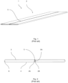
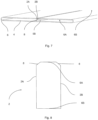
- FIGS. 1 and 2 show the prior art flat tube 1.
- the flat tube 1 may be formed by bending a sheet metal strip 2 along its length.
- Term “metal strip” refers to a metallic sheet comprising two longer sides which may be further referred to as “longitudinal edges” and two substantially shorter sides, substantially parallel to said longer sides.
- the metal strip may be made of, for example, aluminum, yet other materials are also envisaged.
- the metal strip 2 may be bent along its longitudinal edges 2A, 2B to form a closed profile.
- the flat tube 1 may extend along its longitudinal axis. In other words, the flat tube 1 may comprise its axis of elongation.
- the flat tube 1 may further comprise a first wall 3 and a second wall 4 parallel to the first wall 3, wherein said walls 3, 4 are formed after bending the metal strip 2. Said walls 3, 4 may be substantially flat. In order to form a closed profile, the flat tube 1 may further comprise two complementary side wall portions 6 joining said first and second walls 3, 4 together.
- the first fall 3 may comprise a seam 5.
- the seam 5 may extend along the longitudinal axis of the flat tube 1 so that juxtaposed longitudinal edges 2A, 2B of the metal strip 2 join together in parallel manner towards the second wall 4 to form the closed profile of the tube 1.
- the longitudinal edges 2A, 2B are bent inwardly at substantially right angle, so that they protrude towards the second wall 4 and they are in contact with each other substantially from the first wall 3 to the second wall 4.
- the terminal ends of the longitudinal edges 2A, 2B are fixed for example, by brazing to the second wall 4.
- the metal strip 2 may also be brazed along the portion extending between the first wall 3 and the second wall 4, wherein the longitudinal edges 2A and 2B are substantially parallel and in contact with each other. Consequently, the seam 5 may comprise a first section 5A fixed to the second wall 4 and extending along the first portion of the seam 5 along the longitudinal axis of the flat tube 1.
- the seam 5 may comprise the first section 5A fixed to the second wall 4 and extending along the first portion of the seam 5 along the longitudinal axis of the flat tube 1 allows the coolant to circulate within the heat exchanger 100 while providing efficient heat exchange between the coolant and different medium (e.g. air).
- different medium e.g. air
- known tubes tend to crack which may cause coolant leaks, especially in the vicinity of the terminal ends thereof. The cracks may be caused by lack of flexibility of the flat tube 1. Lack of flexibility combined with high pressure and temperature of the coolant may significantly reduce the robustness of the flat tube 1.
- Figures 3-10 show an exemplary solutions which would allow to avoid or mitigate negative aspects of prior art flat tubes 1.
- the seam 5 may comprise a second section 5B.
- the second section 5B may increase the flexibility of the flat tube 1 where needed.
- the second section 5B may extend along the second portion of the seam 5 arranged in series with respect to the first portion of the seam 5 and along the longitudinal axis of the flat tube 1.
- Term "arranged in series” means that the second section 5B is located directly and subsequently to the first section, or that second section 5B is located in the vicinity of the first section 5A whereas there may be another section between them which allows a transition from the first section 5A to the second section 5B.
- the second section 5B may be separated from the second wall 4. More precisely, the second section 5B protrudes from the first wall 3 substantially towards the second wall, yet it does contact the second wall 4. This allows the flat tube 1 to be more flexible during its operational mode. It allows to compensate differences between the pressure and the temperature, so that the flat tube 1 keeps its structural integrity and fluid tightness at all times.
- An exemplary ways of providing the flat tube 1 comprising the second section 5B are discussed in further paragraphs.
- the first way of providing the flat tube 1 comprising the second section 5B is, for example, punching the terminal end of the flat tube 1 with the special tool.
- the goal is to separate the first section 5A from the second wall 4, so that these elements form a gap.
- the first wall 3, the second wall 4 and the side wall portions 6 may remain intact.
- the second section 5B may thus comprise the longitudinal edges 2A, 2B being inclined with respect to the first section 5A towards either of the side walls portions 6.
- the inclination may vary depending on the shape of the tool which formed the second section 5B and it makes no significant difference between the flow of the coolant through the first section 5A of the flat tube 1 and the second section 5B of the flat tube 1.
- the longitudinal edges 2A, 2B forming the second section 5B may be on the same level with respect to the surface of the second wall 4.
- the second section 5B may comprise two portions, both being at the same distance from the second wall 4.
- the flat tube 1 may also comprise at least one dimple (not shown).
- the dimples are not shown for the sake of clarity of the drawings.
- the dimple may be in a form of an indent which is configured to change the flow pattern within the flat tube 1.
- the dimples may be formed on the first wall 3, the second wall 4 or on both walls 3, 4. Usually, the dimples are located along the first section 5A. However, the dimples formed along the second section 5B are also envisaged.
- the seam 5 may comprise a third section 5C extending along the third portion of the seam 5 arranged in series between the first and the second portion of the seam 5 and along the longitudinal axis of the flat tube 1.
- the second section may be located between the first section 5A and the second section 5B.
- the third section 5C may be regarded as the transition zone between the first section 5A and the second section 5B, it may exhibit traits and features of the first section 5A and/ or the second section 5B.
- the gap between the terminal ends of the longitudinal edges 2A, 2B and the second wall 4 may be same as in the first section 5A, wherein the portion of the third section 5C comprising such gap is in the vicinity of the respective, first section 5A.
- the gap between the terminal ends of the longitudinal edges 2A, 2B and the second wall 4 may be same as in the second section 5B, wherein the portion of the third section 5C comprising such gap is in the vicinity of the respective, second section 5B.
- the gap between the third section 5C and the second wall 4 may gradually increase from the first section 5A towards the second section 5B.
- the inclination of the third section 5C may also vary.
- the third section 5C may gradually incline from the first section 5A towards the second section 5B.
- the inclination of the terminal ends of the longitudinal edges 2A, 2B may be same as in the first section 5A, wherein the portion of the third section comprising such inclination is in the vicinity of the respective, first section 5A.
- the inclination of the terminal ends of the longitudinal edges 2A, 2B may be same as in the second section 5B, wherein the portion of the third section 5C comprising such inclination is in the vicinity of the respective, second section 5B.
- the inclination of the third section 5C may gradually increase from the first section 5A towards the second section 5B.
- the flat tube may comprise a first open end 6A and a second open end 6B located on the opposite side to the first open end 6A, with respect to the longitudinal axis of the flat tube 1. Consequently the second section 5B may located in the vicinity of at least one of the first open end 6A, the second open end 6A or both open ends 6A, 6B.
- the second section 5B may be located, for example, in the middle of the flat tube 1 In other words, at least one second section 5B is located between at least two first sections 5A along the longitudinal axis of the flat tube 1.
- this configuration applies only in exceptional cases, wherein the flexibility of the flat tube 1 needs to be increased in desired portion. Usually, the flexibility of the flat tube 1 needs to be increased in the vicinity of the open ends 6A, 6B thereof.
- the alternative way of providing the flat tube 1 comprising the second section 5B is, for example, cutting the longitudinal edges 2A, 2B, so that the seam 5 comprises an incision 7 separating at least the portion of the second section 5B at least from the second wall 4.
- the incision may 7 may be formed by a sharp tool which would be able to cut through the longitudinal edges 2A, 2B substantially in parallel to the surface of the second wall 4.
- the incision 7 may also be formed by a cut at an angle with respect to the surface of the second wall 4.
- the incision 7 may divide the seam 5 into an abscessed portion 7A which is unitary with the longitudinal edges 2A, 2B protruding from the first wall 3, and a remaining portion 7B which remains fixed (e.g. by brazing) with the second wall 4.
- the incision 7 is formed substantially in parallel with respect to the surface of the second wall 4 and along the longitudinal axis of the flat tube 1, yet the incisions of different shape and angle are also envisaged.
- Both aforementioned ways of providing the flat tube 1 comprising the second section 5B refer to a flat tube 1 already formed by a bended metal sheet 2.
- Another way refers to providing the flat tube 1 comprising the second section 5B before bending the metal sheet 2.
- the longitudinal edges 2A, 2B of the metal strip 2 may comprise at least one cutout 8.
- the cutout 8 refers to removal part of the material from the metal strip 2.
- the cutout 8 may be located either in the vicinity of the open ends 6A, 6B, or between them, i.e. at any portion of the metal strip 2 located between the open ends 6A, 6B.
- the cutout 8 may be formed in different shapes and sizes.
- the cutout 8 may comprise at least one right angle so that when the flat tube 1 is formed the second section 5B instantly transfers to the first section 5A.
- the cutout 8 may be formed at an angle, i.e. at an angle between 0 and 90 degrees between the short side of the metal strip 2 and the long side of the metal strip.
- the cutout 8 may gradually bring the longitudinal edge 2A, 2B towards the longitudinal axis of the metal strip 2, wherein the longitudinal axis of the metal strip 2 is located substantially in the middle thereof.
- the non-bended metal strip 2 may comprise at least one substantially trapezoidal portion.
- This form of a cutout 8 is shown in Figs 7 and 8 .
- the cutout 8 may be curved, i.e. it does not form a straight line, but a curved one. The exemplary configuration of such cutout is depicted in Figs 9 and 10 .
- the flat tube 1 may be suitable for a heat exchanger 100.
- the heat exchanger 100 may comprise at least one flat tube 1 comprising at least one second section 5B.
- the exemplary heat exchanger 100 is shown in Figs 11 and 12 .
- the heat exchanger 100 may comprise, inter alia, a first manifold 101 and a second manifold 102, wherein the flat tube 1 is configured to provide a fluidal communication between the manifolds 101, 102.
- the heat exchanger 100 may further comprise at least one secondary tube 103, wherein the secondary tube 103 comprises only the first section 5A extending between the open ends thereof.
- the secondary tube 103 is a known, standard tube.
- the heat exchanger 100 may comprise only flat tubes 1 stacked between the manifolds 101, 102.
- the heat exchanger may comprise at least one flat tube 1 and at least one secondary tube 103. Both flat tubes 1 and the secondary tubes 103 may form at least one first set and at least one second set, respectively.
- the first and the second sets may be arranged in one stack of tubes. In one of the examples, the first set is located at least the terminal end of the stack. Alternatively, at least one first set may be located in-between two adjacent second stacks.
- the manifolds 101, 102 may comprise slots 104 for receiving the tubes 1, 103.
- the second section 5B extends through and beyond the outline of the slots 104 on both of its sides.
- the second section 5B may extend from the open end 6A, 6B of the flat tube along the longitudinal axis of the flat tube 1 to the first section 5A which does not overlap the slot 104 in any case.
- the heat exchanger 100 may also comprise fins 105 interlaced between any of the flat tubes 1 or secondary tubes 103, depending on the presence of the latter.
- the outline of the fins 105 is depicted in Fig. 12 by a dashed line, for the sake of clarity of the drawing.
- the second section 5B extends from the open end 6A, 6B of the flat tube 1 at least to the outline delimited by the terminal end of the fin 105 at the adjacent terminal end thereof.
- the second section 5B extents from 5mm to 25mm form the open end 6A, 6B, along the longitudinal axis of the flat tube 1.
Landscapes
- Engineering & Computer Science (AREA)
- Physics & Mathematics (AREA)
- Thermal Sciences (AREA)
- Mechanical Engineering (AREA)
- General Engineering & Computer Science (AREA)
- Geometry (AREA)
- Heat-Exchange Devices With Radiators And Conduit Assemblies (AREA)
Priority Applications (4)
| Application Number | Priority Date | Filing Date | Title |
|---|---|---|---|
| EP21199440.5A EP4155651B1 (de) | 2021-09-28 | 2021-09-28 | Flachrohr für einen wärmetauscher |
| CN202280075941.4A CN118355243A (zh) | 2021-09-28 | 2022-09-01 | 用于热交换器的扁平管 |
| PCT/EP2022/074371 WO2023052032A1 (en) | 2021-09-28 | 2022-09-01 | A flat tube for a heat exchanger |
| US18/694,036 US20240393062A1 (en) | 2021-09-28 | 2022-09-01 | Flat tube for a heat exchanger |
Applications Claiming Priority (1)
| Application Number | Priority Date | Filing Date | Title |
|---|---|---|---|
| EP21199440.5A EP4155651B1 (de) | 2021-09-28 | 2021-09-28 | Flachrohr für einen wärmetauscher |
Publications (2)
| Publication Number | Publication Date |
|---|---|
| EP4155651A1 true EP4155651A1 (de) | 2023-03-29 |
| EP4155651B1 EP4155651B1 (de) | 2025-03-26 |
Family
ID=77998891
Family Applications (1)
| Application Number | Title | Priority Date | Filing Date |
|---|---|---|---|
| EP21199440.5A Active EP4155651B1 (de) | 2021-09-28 | 2021-09-28 | Flachrohr für einen wärmetauscher |
Country Status (4)
| Country | Link |
|---|---|
| US (1) | US20240393062A1 (de) |
| EP (1) | EP4155651B1 (de) |
| CN (1) | CN118355243A (de) |
| WO (1) | WO2023052032A1 (de) |
Citations (3)
| Publication number | Priority date | Publication date | Assignee | Title |
|---|---|---|---|---|
| US20090050306A1 (en) * | 2007-08-20 | 2009-02-26 | Behr Gmbh & Co. Kg | Multi chamber flat pipe, heat exchanger, and use of a heat exchanger |
| DE102008007597A1 (de) * | 2008-02-04 | 2009-08-06 | Behr Gmbh & Co. Kg | Herstellungsverfahren Mehrkammer-Flachrohr, Wärmetauscher und Verwendung eines Wärmetauschers |
| US20200011606A1 (en) * | 2018-07-03 | 2020-01-09 | Ford Global Technologies, Llc | Notched coolant tubes for a heat exchanger |
Family Cites Families (3)
| Publication number | Priority date | Publication date | Assignee | Title |
|---|---|---|---|---|
| ES2266331T3 (es) * | 2001-04-28 | 2007-03-01 | BEHR GMBH & CO. KG | Tubo plano multicamara plegado. |
| KR100826023B1 (ko) * | 2006-12-28 | 2008-04-28 | 엘지전자 주식회사 | 환기 장치의 열교환기 |
| US10508870B2 (en) * | 2016-10-14 | 2019-12-17 | Hanon Systems | B-tube reform for improved thermal cycle performance |
-
2021
- 2021-09-28 EP EP21199440.5A patent/EP4155651B1/de active Active
-
2022
- 2022-09-01 CN CN202280075941.4A patent/CN118355243A/zh active Pending
- 2022-09-01 US US18/694,036 patent/US20240393062A1/en active Pending
- 2022-09-01 WO PCT/EP2022/074371 patent/WO2023052032A1/en not_active Ceased
Patent Citations (3)
| Publication number | Priority date | Publication date | Assignee | Title |
|---|---|---|---|---|
| US20090050306A1 (en) * | 2007-08-20 | 2009-02-26 | Behr Gmbh & Co. Kg | Multi chamber flat pipe, heat exchanger, and use of a heat exchanger |
| DE102008007597A1 (de) * | 2008-02-04 | 2009-08-06 | Behr Gmbh & Co. Kg | Herstellungsverfahren Mehrkammer-Flachrohr, Wärmetauscher und Verwendung eines Wärmetauschers |
| US20200011606A1 (en) * | 2018-07-03 | 2020-01-09 | Ford Global Technologies, Llc | Notched coolant tubes for a heat exchanger |
Also Published As
| Publication number | Publication date |
|---|---|
| US20240393062A1 (en) | 2024-11-28 |
| WO2023052032A1 (en) | 2023-04-06 |
| CN118355243A (zh) | 2024-07-16 |
| EP4155651B1 (de) | 2025-03-26 |
Similar Documents
| Publication | Publication Date | Title |
|---|---|---|
| JP4175443B2 (ja) | 熱交換器 | |
| US8074708B2 (en) | Heat exchanger | |
| US5441106A (en) | Heat exchange tubes | |
| JP4171760B2 (ja) | 偏平管および偏平管の製造方法 | |
| MX2011004502A (es) | Aleta para un intercambiador de calor e intercambiador de calor que incluye tal aleta. | |
| CN103925826A (zh) | 热交换器用管 | |
| CN113544457B (zh) | 换热器 | |
| EP0838650B1 (de) | Wärmetauscher mit verbeulten Rippenplatten | |
| KR100336712B1 (ko) | 플레이트-핀 형 열교환기 및 그의 제조방법 | |
| EP4155651B1 (de) | Flachrohr für einen wärmetauscher | |
| JP2012137251A (ja) | 多管式熱交換器 | |
| US10888910B2 (en) | Machining method for burred flat holes in metal plates | |
| US20060249277A1 (en) | Method of producing a heat exchanger module | |
| US6971444B2 (en) | Heat exchanger construction and method | |
| US7413002B2 (en) | Corrugated fin and heat exchanger using the same | |
| EP3767217B1 (de) | Röhre für einen wärmetauscher | |
| EP4273489B1 (de) | Flachröhre für einen wärmetauscher | |
| EP4497984A1 (de) | Flachrohr für einen wärmetauscher | |
| CN105051480B (zh) | 热交换器 | |
| KR100666927B1 (ko) | 헤더형 열교환기 | |
| KR101006906B1 (ko) | 열교환기용 일체형 튜브 | |
| US10041742B2 (en) | Heat exchanger side plate with fin |
Legal Events
| Date | Code | Title | Description |
|---|---|---|---|
| PUAI | Public reference made under article 153(3) epc to a published international application that has entered the european phase |
Free format text: ORIGINAL CODE: 0009012 |
|
| STAA | Information on the status of an ep patent application or granted ep patent |
Free format text: STATUS: THE APPLICATION HAS BEEN PUBLISHED |
|
| AK | Designated contracting states |
Kind code of ref document: A1 Designated state(s): AL AT BE BG CH CY CZ DE DK EE ES FI FR GB GR HR HU IE IS IT LI LT LU LV MC MK MT NL NO PL PT RO RS SE SI SK SM TR |
|
| STAA | Information on the status of an ep patent application or granted ep patent |
Free format text: STATUS: REQUEST FOR EXAMINATION WAS MADE |
|
| 17P | Request for examination filed |
Effective date: 20230929 |
|
| RBV | Designated contracting states (corrected) |
Designated state(s): AL AT BE BG CH CY CZ DE DK EE ES FI FR GB GR HR HU IE IS IT LI LT LU LV MC MK MT NL NO PL PT RO RS SE SI SK SM TR |
|
| GRAP | Despatch of communication of intention to grant a patent |
Free format text: ORIGINAL CODE: EPIDOSNIGR1 |
|
| STAA | Information on the status of an ep patent application or granted ep patent |
Free format text: STATUS: GRANT OF PATENT IS INTENDED |
|
| INTG | Intention to grant announced |
Effective date: 20241025 |
|
| GRAS | Grant fee paid |
Free format text: ORIGINAL CODE: EPIDOSNIGR3 |
|
| GRAA | (expected) grant |
Free format text: ORIGINAL CODE: 0009210 |
|
| STAA | Information on the status of an ep patent application or granted ep patent |
Free format text: STATUS: THE PATENT HAS BEEN GRANTED |
|
| AK | Designated contracting states |
Kind code of ref document: B1 Designated state(s): AL AT BE BG CH CY CZ DE DK EE ES FI FR GB GR HR HU IE IS IT LI LT LU LV MC MK MT NL NO PL PT RO RS SE SI SK SM TR |
|
| REG | Reference to a national code |
Ref country code: GB Ref legal event code: FG4D |
|
| REG | Reference to a national code |
Ref country code: CH Ref legal event code: EP |
|
| REG | Reference to a national code |
Ref country code: DE Ref legal event code: R096 Ref document number: 602021028052 Country of ref document: DE |
|
| REG | Reference to a national code |
Ref country code: IE Ref legal event code: FG4D |
|
| PG25 | Lapsed in a contracting state [announced via postgrant information from national office to epo] |
Ref country code: RS Free format text: LAPSE BECAUSE OF FAILURE TO SUBMIT A TRANSLATION OF THE DESCRIPTION OR TO PAY THE FEE WITHIN THE PRESCRIBED TIME-LIMIT Effective date: 20250626 |
|
| PG25 | Lapsed in a contracting state [announced via postgrant information from national office to epo] |
Ref country code: FI Free format text: LAPSE BECAUSE OF FAILURE TO SUBMIT A TRANSLATION OF THE DESCRIPTION OR TO PAY THE FEE WITHIN THE PRESCRIBED TIME-LIMIT Effective date: 20250326 |
|
| REG | Reference to a national code |
Ref country code: LT Ref legal event code: MG9D |
|
| PG25 | Lapsed in a contracting state [announced via postgrant information from national office to epo] |
Ref country code: NO Free format text: LAPSE BECAUSE OF FAILURE TO SUBMIT A TRANSLATION OF THE DESCRIPTION OR TO PAY THE FEE WITHIN THE PRESCRIBED TIME-LIMIT Effective date: 20250626 |
|
| PG25 | Lapsed in a contracting state [announced via postgrant information from national office to epo] |
Ref country code: HR Free format text: LAPSE BECAUSE OF FAILURE TO SUBMIT A TRANSLATION OF THE DESCRIPTION OR TO PAY THE FEE WITHIN THE PRESCRIBED TIME-LIMIT Effective date: 20250326 |
|
| PG25 | Lapsed in a contracting state [announced via postgrant information from national office to epo] |
Ref country code: LV Free format text: LAPSE BECAUSE OF FAILURE TO SUBMIT A TRANSLATION OF THE DESCRIPTION OR TO PAY THE FEE WITHIN THE PRESCRIBED TIME-LIMIT Effective date: 20250326 |
|
| PG25 | Lapsed in a contracting state [announced via postgrant information from national office to epo] |
Ref country code: GR Free format text: LAPSE BECAUSE OF FAILURE TO SUBMIT A TRANSLATION OF THE DESCRIPTION OR TO PAY THE FEE WITHIN THE PRESCRIBED TIME-LIMIT Effective date: 20250627 Ref country code: BG Free format text: LAPSE BECAUSE OF FAILURE TO SUBMIT A TRANSLATION OF THE DESCRIPTION OR TO PAY THE FEE WITHIN THE PRESCRIBED TIME-LIMIT Effective date: 20250326 |
|
| REG | Reference to a national code |
Ref country code: NL Ref legal event code: MP Effective date: 20250326 |
|
| PG25 | Lapsed in a contracting state [announced via postgrant information from national office to epo] |
Ref country code: NL Free format text: LAPSE BECAUSE OF FAILURE TO SUBMIT A TRANSLATION OF THE DESCRIPTION OR TO PAY THE FEE WITHIN THE PRESCRIBED TIME-LIMIT Effective date: 20250326 |
|
| PG25 | Lapsed in a contracting state [announced via postgrant information from national office to epo] |
Ref country code: SE Free format text: LAPSE BECAUSE OF FAILURE TO SUBMIT A TRANSLATION OF THE DESCRIPTION OR TO PAY THE FEE WITHIN THE PRESCRIBED TIME-LIMIT Effective date: 20250326 |
|
| REG | Reference to a national code |
Ref country code: AT Ref legal event code: MK05 Ref document number: 1779332 Country of ref document: AT Kind code of ref document: T Effective date: 20250326 |
|
| PG25 | Lapsed in a contracting state [announced via postgrant information from national office to epo] |
Ref country code: SM Free format text: LAPSE BECAUSE OF FAILURE TO SUBMIT A TRANSLATION OF THE DESCRIPTION OR TO PAY THE FEE WITHIN THE PRESCRIBED TIME-LIMIT Effective date: 20250326 |
|
| PG25 | Lapsed in a contracting state [announced via postgrant information from national office to epo] |
Ref country code: ES Free format text: LAPSE BECAUSE OF FAILURE TO SUBMIT A TRANSLATION OF THE DESCRIPTION OR TO PAY THE FEE WITHIN THE PRESCRIBED TIME-LIMIT Effective date: 20250326 Ref country code: PT Free format text: LAPSE BECAUSE OF FAILURE TO SUBMIT A TRANSLATION OF THE DESCRIPTION OR TO PAY THE FEE WITHIN THE PRESCRIBED TIME-LIMIT Effective date: 20250728 |
|
| PGFP | Annual fee paid to national office [announced via postgrant information from national office to epo] |
Ref country code: DE Payment date: 20250916 Year of fee payment: 5 |
|
| PG25 | Lapsed in a contracting state [announced via postgrant information from national office to epo] |
Ref country code: IT Free format text: LAPSE BECAUSE OF FAILURE TO SUBMIT A TRANSLATION OF THE DESCRIPTION OR TO PAY THE FEE WITHIN THE PRESCRIBED TIME-LIMIT Effective date: 20250326 Ref country code: PL Free format text: LAPSE BECAUSE OF FAILURE TO SUBMIT A TRANSLATION OF THE DESCRIPTION OR TO PAY THE FEE WITHIN THE PRESCRIBED TIME-LIMIT Effective date: 20250326 |
|
| PG25 | Lapsed in a contracting state [announced via postgrant information from national office to epo] |
Ref country code: AT Free format text: LAPSE BECAUSE OF FAILURE TO SUBMIT A TRANSLATION OF THE DESCRIPTION OR TO PAY THE FEE WITHIN THE PRESCRIBED TIME-LIMIT Effective date: 20250326 |
|
| PGFP | Annual fee paid to national office [announced via postgrant information from national office to epo] |
Ref country code: FR Payment date: 20250929 Year of fee payment: 5 |
|
| PG25 | Lapsed in a contracting state [announced via postgrant information from national office to epo] |
Ref country code: EE Free format text: LAPSE BECAUSE OF FAILURE TO SUBMIT A TRANSLATION OF THE DESCRIPTION OR TO PAY THE FEE WITHIN THE PRESCRIBED TIME-LIMIT Effective date: 20250326 |
|
| PG25 | Lapsed in a contracting state [announced via postgrant information from national office to epo] |
Ref country code: RO Free format text: LAPSE BECAUSE OF FAILURE TO SUBMIT A TRANSLATION OF THE DESCRIPTION OR TO PAY THE FEE WITHIN THE PRESCRIBED TIME-LIMIT Effective date: 20250326 |
|
| PG25 | Lapsed in a contracting state [announced via postgrant information from national office to epo] |
Ref country code: SK Free format text: LAPSE BECAUSE OF FAILURE TO SUBMIT A TRANSLATION OF THE DESCRIPTION OR TO PAY THE FEE WITHIN THE PRESCRIBED TIME-LIMIT Effective date: 20250326 |
|
| PG25 | Lapsed in a contracting state [announced via postgrant information from national office to epo] |
Ref country code: IS Free format text: LAPSE BECAUSE OF FAILURE TO SUBMIT A TRANSLATION OF THE DESCRIPTION OR TO PAY THE FEE WITHIN THE PRESCRIBED TIME-LIMIT Effective date: 20250726 |
|
| REG | Reference to a national code |
Ref country code: DE Ref legal event code: R097 Ref document number: 602021028052 Country of ref document: DE |
|
| PG25 | Lapsed in a contracting state [announced via postgrant information from national office to epo] |
Ref country code: DK Free format text: LAPSE BECAUSE OF FAILURE TO SUBMIT A TRANSLATION OF THE DESCRIPTION OR TO PAY THE FEE WITHIN THE PRESCRIBED TIME-LIMIT Effective date: 20250326 |
|
| PG25 | Lapsed in a contracting state [announced via postgrant information from national office to epo] |
Ref country code: CZ Free format text: LAPSE BECAUSE OF FAILURE TO SUBMIT A TRANSLATION OF THE DESCRIPTION OR TO PAY THE FEE WITHIN THE PRESCRIBED TIME-LIMIT Effective date: 20250326 |
|
| PLBE | No opposition filed within time limit |
Free format text: ORIGINAL CODE: 0009261 |
|
| STAA | Information on the status of an ep patent application or granted ep patent |
Free format text: STATUS: NO OPPOSITION FILED WITHIN TIME LIMIT |
|
| REG | Reference to a national code |
Ref country code: CH Ref legal event code: L10 Free format text: ST27 STATUS EVENT CODE: U-0-0-L10-L00 (AS PROVIDED BY THE NATIONAL OFFICE) Effective date: 20260211 |
|
| 26N | No opposition filed |
Effective date: 20260105 |
|
| REG | Reference to a national code |
Ref country code: CH Ref legal event code: H13 Free format text: ST27 STATUS EVENT CODE: U-0-0-H10-H13 (AS PROVIDED BY THE NATIONAL OFFICE) Effective date: 20260425 |