EP4155657A1 - Liquid distribution system for cooling or fire-fighting installations - Google Patents
Liquid distribution system for cooling or fire-fighting installations Download PDFInfo
- Publication number
- EP4155657A1 EP4155657A1 EP22197541.0A EP22197541A EP4155657A1 EP 4155657 A1 EP4155657 A1 EP 4155657A1 EP 22197541 A EP22197541 A EP 22197541A EP 4155657 A1 EP4155657 A1 EP 4155657A1
- Authority
- EP
- European Patent Office
- Prior art keywords
- central axis
- liquid
- deflector
- central
- distribution system
- Prior art date
- Legal status (The legal status is an assumption and is not a legal conclusion. Google has not performed a legal analysis and makes no representation as to the accuracy of the status listed.)
- Granted
Links
Images

Classifications
-
- B—PERFORMING OPERATIONS; TRANSPORTING
- B05—SPRAYING OR ATOMISING IN GENERAL; APPLYING FLUENT MATERIALS TO SURFACES, IN GENERAL
- B05B—SPRAYING APPARATUS; ATOMISING APPARATUS; NOZZLES
- B05B3/00—Spraying or sprinkling apparatus with moving outlet elements or moving deflecting elements
- B05B3/02—Spraying or sprinkling apparatus with moving outlet elements or moving deflecting elements with rotating elements
- B05B3/04—Spraying or sprinkling apparatus with moving outlet elements or moving deflecting elements with rotating elements driven by the liquid or other fluent material discharged, e.g. the liquid actuating a motor before passing to the outlet
- B05B3/0417—Spraying or sprinkling apparatus with moving outlet elements or moving deflecting elements with rotating elements driven by the liquid or other fluent material discharged, e.g. the liquid actuating a motor before passing to the outlet comprising a liquid driven rotor, e.g. a turbine
- B05B3/0425—Spraying or sprinkling apparatus with moving outlet elements or moving deflecting elements with rotating elements driven by the liquid or other fluent material discharged, e.g. the liquid actuating a motor before passing to the outlet comprising a liquid driven rotor, e.g. a turbine actuated downstream of the outlet elements
- B05B3/0426—Spraying or sprinkling apparatus with moving outlet elements or moving deflecting elements with rotating elements driven by the liquid or other fluent material discharged, e.g. the liquid actuating a motor before passing to the outlet comprising a liquid driven rotor, e.g. a turbine actuated downstream of the outlet elements the liquid driven rotor being a deflecting rotating element
-
- A—HUMAN NECESSITIES
- A62—LIFE-SAVING; FIRE-FIGHTING
- A62C—FIRE-FIGHTING
- A62C35/00—Permanently-installed equipment
- A62C35/58—Pipe-line systems
- A62C35/68—Details, e.g. of pipes or valve systems
Definitions
- the present invention relates to a liquid distribution system for cooling or fire-fighting installations of the kind recited in the preamble of the first claim.
- the present invention relates to a distributor of a liquid such as water, suitable for being connected to pipes included in a network of external distribution.
- distributors Under the various kinds of distributors, atomisers and nebulizers are well known. These distributors are substantially configured to receive a fluid flow and convert it into a plurality of particles. Then, these particles are distributed rather uniformly on a surface.
- the sprinklers are indeed delivering a liquid rain, generally used to extinguish fires, comprising a body, a thermosensitive element, a plug, an orifice and a baffle.
- the baffle is generally installed on the body of the sprinkler, on the part opposite to the orifice.
- the baffle substantially divides the flow of water discharged from the orifice, so as to warrant a higher extinguishing power.
- Other distributors may instead comprise rotary baffle plates.
- These rotary baffle plates are active elements, controlled to rotate around its own axis, and configured to distribute water in view of the centrifugal force distributed thereon.
- the baffle plates comprise two opposed ducts connected to a central duct, wherefrom water flows to be discharged from the jointly rotating opposed ducts.
- the described prior art has some important drawbacks. More particularly, the devices provided with atomizers or nebulizers require pressurized liquid or additional components for pressurization of the liquid reaching the outlet nozzle.
- the devices provided with static baffle plates are generally not fully effective, while devices provided with rotary baffle plates comprise feeding means to control the rotary motion of the baffle plates, with obvious increase of both structural complexity and related costs.
- the basic technical problem of the present invention is to provide a distributor of liquids for cooling or fire-fighting installations, adapted to substantially get round at least part of the above mentioned drawbacks.
- Another important scope of the invention is to carry out a distributor of liquid for cooling or fire-fighting installations, which is simple and economic.
- measures, values, forms and geometrical references when associated with words like “about” or other similar terms like “almost” or “substantially”, should be understood as excluding measurement errors or inaccuracies due to manufacture and/or production errors, and above all excluding a slight deviation from the associated value, measure, form or geometric reference.
- these terms when associated with a value, preferably mean a deviation not higher than 10% of said value.
- treatment refers to the action and/or process of a computer or similar device of electronic calculation, treating and/or transforming data represented as physical ones, such as electronic quantities of registers of an information system and/or memory into other data likewise represented as physical quantities inside information systems, registers or other devices to store, transmit or show information.
- liquid distributor for cooling or fire-fighting installations is globally indicated with reference number 1.
- the distributor 1 may also be equally used inside a cooling plant or inside a fire-fighting installation.
- the distributor 1 is fitted for supplying water in the form of jets and/or droplets made by acting on the water flow hitting the distributor 1.
- the distributor 1 is suitable for being connected to pipes included in an external hydraulic distribution network, so as to supply continuously the water conveyed thereinto from the external hydraulic network.
- the distributor 1 comprises at least a duct 2.
- Duct 2 is preferably configured to convey a liquid along one direction. More particularly, duct 2 conveys the fluid parallel to or along its central axis 2a.
- Central axis 2 is the axis around which duct 2 is mainly developed. Therefore duct 2 is substantially a tubular body extending along the central axis 2a.
- Conveyance is preferably carried out passively.
- the fluid i.e. water
- duct 2 autonomously preferably by gravity. Therefore, in this connection, central axis 2a of duct 2 is suitable to be arranged at right angles to ground, when the distributor 1 is being used.
- Duct 2 may also be a single piece, or may include a tubular container 20, inside which an extractible cartridge 21 may be arranged.
- the tubular container 20 is a containing element preferably including a lower border, namely at an end facing the ground and configured to prevent the cartridge 21 to slide downwards. Said cartridge may be inserted into the tubular container 20 and removed therefrom, by causing the cartridge to slide along the central axis 2a. Therefore, the cartridge may be shaped externally along the tubular container 20 and may define a variable internal opening.
- duct 2 and consequently the tubular container 20 and the cartridge 21 may define either a cylindrical or most preferably truncated conical shape.
- the distributor 1 comprises also a concentrator 3.
- the concentrator 3 substantially is a component suitable for directing the fluid into a predetermined concentration area 3a.
- a concentration area 3a is substantially an area that can be defined along a plane transversal to the central axis 2a. More particularly, the concentration area 3a is defined in a main plane 2b at right angles with the central axis 2a.
- the plane is a virtual element on which the concentration area 3a my still virtually be defined.
- the concentrator 3 as a structure is integrally constrained to duct 2, and is spaced from duct 2 along the central axis 2a. Therefore, the fluid falling from duct 2 hits the concentrator 3 and is sent to the concentration area 3a.
- the concentrator 3 is just configured to concentrate the liquid in the concentration area 3a.
- the constraint between duct 2 and concentrator 3 may be carried out by different modes.
- the distributor 1 may comprise a frame 5.
- Frame 5 substantially is a support and connection element for duct 2 and concentrator 3. Therefore, frame 5 may ne a further component to be constrained to duct 2 and concentrator 3, or it may be integral with duct 2, more particularly the tubular container 20, and with concentrator 3. Thus, in turn, at least a portion of duct 2 and concentrator 3 may be integral.
- Frame 5 preferably is U-shaped and therefore is configured to mutually connect duct 2 and concentrator 3, surrounding said concentrator 3.
- Concentrator 3 may comprise an envelope 32 and two arms 33.
- the envelope 32 substantially is a preferably at least partially hollow body extending along the main axis 2a.
- envelope 32 preferably comprises a first barrel shaped portion 32a adjacent to deflector 4 and a second portion 32b defining a paraboloid shape. Therefore, envelope 32 defines a shape like an aircraft fuselage, with the front portion defined by the second portion 32b. Thus, the liquid coming from duct 2 substantially hits the second portion 32b and flows along the first portion 32a before falling on the deflector 4, like air flows around an aircraft fuselage.
- Arms 33 are preferably arranged transversal, for instance perpendicular to main axis 2a. Moreover, arms 33 are integrally constrained to envelope 32 and frame 5 at the opposite sides of envelope 32.
- arms 33 define sections on planes parallel to main axis 2a, like wing contours with a leading edge facing duct 2.
- the concentration area 3a substantially encloses an area including at least envelope 32 and arms 33.
- the distributor 1 comprises also a deflector 4.
- Deflector 4 preferably has a labile constraint with concentrator 3. More particularly, deflector 4 may rotate around the main axis 2a, for instance in respect of the concentrator 3.
- the deflector 4 is arranged in connection of fluidic passage with the concentration area. This means that the deflector 4 is substantially adapted to receive the liquid passing through the concentration area 3a in order to deflect the direction of movement of said flow. Indeed, the deflector 4 is configured to deflect the liquid along radial trajectories 4a.
- the radial trajectories 4a are at least partially transversal to the central axis 2a. Indeed, the radial trajectories 4a extend at least from the central axis 2a to the outside, distributed around the central axis 2a. However, the radial trajectories 4a might also extend partially parallel to the central axis 2a. Preferably, the radial trajectories 4a are extending both transversally and partially around the central axis 2a.
- the deflector 4 comprises a plurality of blades 40.
- the blades 40 are extending along radial trajectories 4a.
- blades 40 are configured to push, when hit by liquid, deflector 4 to rotate around the main axis 2a. Therefore, the deflector 4 is thrusted to rotate, preferably by gravity, by the liquid incoming from the concentration area 3a. With such a rotation, the deflector 4 allows the liquid to branch out along the radial trajectories, thus being subdivided into a plurality of streamlets, then divided into droplets.
- the radial trajectories 4a are curvilinear and diverging in respect of the central axis 2a. More particularly, they are advantageously diverging to ground.
- the radial trajectories 4a are at least partially helicoidal.
- the blades 40 have walls that extend at least partially in a helicoidal way.
- the deflector 4 comprises also a plurality of distribution surfaces 41.
- the distribution surfaces 41 are preferably transversal and integral with blades 40.
- the distribution surfaces 41 a are substantially diverging from the central axis 2a, and each surface is configured to connect two adjacent blades 40. Therefore, the distribution surfaces substantially define the radial trajectories 4a, because the liquid flows on them, once the concentration area 3a is passed.
- the deflector 4 moreover comprises a plurality of fins 42.
- Each fin 42 preferably is transversal and integral with a corresponding distribution surface 41.
- each fin 42 extends along curvilinear trajectories radially to the central axis 2a.
- each fin 42 may extend substantially along a corresponding radial trajectory 4a.
- the fins 42 extend at the free end of the distribution surfaces 41. In this way, the liquid reaches the fins 42 shortly before leaving the deflector 4.
- the distributor 1 preferably is provided with some measures. More particularly, the concentrator comprises a first central body 30.
- the central body 30 is substantially aligned with the central axis 2a. Thus, it is an oblong element like for instance a pivot.
- the first central body 30 comprises a stem 30a. Stem 30a is therefore aligned with the main axis 2a.
- the first central body 30 comprises also two heads 30b.
- the heads 30b substantially are mutually separated by the stem 30a, and therefore are mutually spaced along the main axis 2a. Moreover, the heads 30b define greater sections along planes perpendicular to the main axis 2a in respect of the stem 30a.
- the first central body 30 is particularly integral with the envelope 32. Still in greater detail, envelope 32 comprises the first central body 30, or he first central body 30 extends along the main axis 2a surrounded by envelope 32.
- Deflector 4 comprises instead a second central body 43.
- the second central body 43 is preferably hollow.
- the second central body 43 is the element around which blades 40 and distribution surfaces 41 are extending.
- the second central body 43 is configured to be connected to the first central body 30. Therefore, the latter is so inserted in the second central body 43 in such a way that the second central body 43 may rotate in respect of the first central body 30.
- the cavity of the second central body 43 extends along the main axis 2a so as to receive the first central body 30.
- heads 30b of the central body 30 are so configured as to contact the central body 43, so that between stem 30a and second central body 43 there is a gap 31.
- the gap 31 substantially is the enclosed space between stem 30a, heads 30b and second central body 43.
- the second central body 43 constrained with the first central body 30, is also substantially enclosed at least partially in envelope 32.
- the second central body 43 might also not be a single piece, and as shown in Fig. 3 , may comprise two hollow elements being concentric with the central axis 2a, where the inner element, shown without the outer element in Fig. 4 , is suitable for being connected to the first central body 30, thus providing for the gap 31.
- the outer element may include an upper shoulder in order to block the translation of the inner element in respect of the central axis 2a.
- the second central body 43 may also comprise further elements, for instance a washer and/or a bolt, as shown in Fig. 4 , to be constrained to the first central body 30 under said first central body 30, to block together with the shoulder of the first element, the translation of the inner element in respect of the outer element.
- the envelope 32 is configured to surround the second central body 43, without contacting the second central body, when the distributor 1 is being used. In this way, between envelope 32 and second central body 43 there is provided a leak 34.
- This leak 34 therefore is an opening through which at least a portion of liquid may percolate, so as to lubricate said central bodies 30, 43.
- the operation of the distributor is the following: In substance, the liquid is conveyed by gravity throughout the duct 2 parallel to main axis 2a; then the liquid reaches the concentrator3, where it hits the second portion 32b of envelope 32 and the arms 33, being conveyed to the concentration area 3a. After the concentration area 3a, the liquid stands on the blades 40, so as to cause the deflector 4 to rotate, and on the distribution surfaces 41 so as to be radially conveyed along the radial trajectories 4a through the fins 42. The liquid coming out from the deflector 4 is then distributed in the form of droplets and/or intermittent stream lets.
- the distributor 1 attains important advantages. Indeed, the distributor 1 of liquid for cooling or fire-fighting installations allows to deliver liquid undergoing any pressure, advantageously through simple fall by gravity. Moreover, the distributor 1 defines a simple and economic structure. Additionally, the distributor 1 is extremely efficient and does not need active control or feeding devices that may burden the global structure.
- the leak 34 allows to keep the bodies 30, 43 always lubricated.
Landscapes
- Health & Medical Sciences (AREA)
- Public Health (AREA)
- Business, Economics & Management (AREA)
- Emergency Management (AREA)
- Nozzles (AREA)
Abstract
Description
- The present invention relates to a liquid distribution system for cooling or fire-fighting installations of the kind recited in the preamble of the first claim.
- More particularly, the present invention relates to a distributor of a liquid such as water, suitable for being connected to pipes included in a network of external distribution.
- It is well known that in industrial environments for productions processes comprising plants operating at high temperatures, it may be advisable to use also cooling systems adapted to reduce the local operative temperature of the installations.
- Moreover, inside any environment, one may often find fire-fighting installations for extinguishing any flame arisen inside the environment, for instance using water or nebulized fire-fighting liquid.
- Therefore, in the conventional cooling and/or fire-fighting installations, it is possible to find distributors suitable to allow the distribution of water, or other suitable liquid, in a specific form, such as droplets, cascade and so on.
- Under the various kinds of distributors, atomisers and nebulizers are well known. These distributors are substantially configured to receive a fluid flow and convert it into a plurality of particles. Then, these particles are distributed rather uniformly on a surface.
- The sprinklers are indeed delivering a liquid rain, generally used to extinguish fires, comprising a body, a thermosensitive element, a plug, an orifice and a baffle.
- The baffle is generally installed on the body of the sprinkler, on the part opposite to the orifice.
- Therefore, the baffle substantially divides the flow of water discharged from the orifice, so as to warrant a higher extinguishing power.
- Other distributors, mainly used for irrigation, may instead comprise rotary baffle plates. These rotary baffle plates are active elements, controlled to rotate around its own axis, and configured to distribute water in view of the centrifugal force distributed thereon. Generally, the baffle plates comprise two opposed ducts connected to a central duct, wherefrom water flows to be discharged from the jointly rotating opposed ducts.
- The described prior art has some important drawbacks. More particularly, the devices provided with atomizers or nebulizers require pressurized liquid or additional components for pressurization of the liquid reaching the outlet nozzle.
- The devices provided with static baffle plates are generally not fully effective, while devices provided with rotary baffle plates comprise feeding means to control the rotary motion of the baffle plates, with obvious increase of both structural complexity and related costs.
- In this situation, the basic technical problem of the present invention is to provide a distributor of liquids for cooling or fire-fighting installations, adapted to substantially get round at least part of the above mentioned drawbacks.
- Within the scope of said technical problem, it is an important object of the invention to make a liquid distribution system for cooling or fire-fighting installations, allowing to supply liquid under any pressure, for instance merely falling due to gravity.
- Another important scope of the invention is to carry out a distributor of liquid for cooling or fire-fighting installations, which is simple and economic.
- More particularly, it is an important object of the invention to carry out a distributor which is very efficient and at the same time does not require active controlling or feeding devices which might burden the global structure.
- The abovementioned technical objects and problems are solved by a liquid distribution system for cooling or fire-fighting installations as recited in the annexed
claim 1. Preferred technical solutions are pointed out in the dependent claims. - The features and advantages of the invention are hereinafter clarified by the detailed description of preferred embodiments of the invention, making reference to the accompanying drawings, in which:
-
Fig. 1 is a perspective view of a liquid distributor for cooling or fire-fighting installations of the invention; -
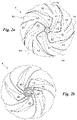
Fig. 2a shows a top view of the baffle plate of a liquid distributor for cooling or fire-fighting installations according to the invention; -
Fig. 2b shows a bottom view of the baffle plate of a liquid distributor for cooling or fire-fighting installations according to the invention; -
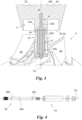
Fig. 3 is a detailed front sectional view of a liquid distributor for cooling or fire-fighting installation according to the invention; and -
Fig. 4 is an exploded detailed view of the central parts of a liquid distributor for cooling or fire-fighting installation according to the invention. - In this document, measures, values, forms and geometrical references (such as verticality and parallelism), when associated with words like "about" or other similar terms like "almost" or "substantially", should be understood as excluding measurement errors or inaccuracies due to manufacture and/or production errors, and above all excluding a slight deviation from the associated value, measure, form or geometric reference. For instance, these terms, when associated with a value, preferably mean a deviation not higher than 10% of said value.
- Moreover, when used, terms like "first", "second", "upper", "lower", "main", "secondary" do not necessarily identify an order, a priority of relation or position, but they may be simply used to clearly distinguish different components.
- Unless otherwise specified, as resulting from the following discussions, it is to be noted that terms like "treatment", "information", "determination" "computation" and the like, refer to the action and/or process of a computer or similar device of electronic calculation, treating and/or transforming data represented as physical ones, such as electronic quantities of registers of an information system and/or memory into other data likewise represented as physical quantities inside information systems, registers or other devices to store, transmit or show information.
- The measurements and data given in the present document are to be considered, unless otherwise stated, as obtained under International Standard Atmosphere ICAO (ISO 2533:1975).
- With reference now to the figures of the drawings, the liquid distributor for cooling or fire-fighting installations according to the present invention is globally indicated with
reference number 1. - The
distributor 1 may also be equally used inside a cooling plant or inside a fire-fighting installation. - Generally speaking, the
distributor 1 is fitted for supplying water in the form of jets and/or droplets made by acting on the water flow hitting thedistributor 1. - Moreover, the
distributor 1 is suitable for being connected to pipes included in an external hydraulic distribution network, so as to supply continuously the water conveyed thereinto from the external hydraulic network. Briefly, thedistributor 1 comprises at least aduct 2. Duct 2 is preferably configured to convey a liquid along one direction. More particularly,duct 2 conveys the fluid parallel to or along itscentral axis 2a. -
Central axis 2 is the axis around whichduct 2 is mainly developed. Thereforeduct 2 is substantially a tubular body extending along thecentral axis 2a. - Conveyance is preferably carried out passively. This means that the fluid, i.e. water, preferably is introduced into
duct 2 autonomously, preferably by gravity. Therefore, in this connection,central axis 2a ofduct 2 is suitable to be arranged at right angles to ground, when thedistributor 1 is being used. - Duct 2 may also be a single piece, or may include a
tubular container 20, inside which anextractible cartridge 21 may be arranged. - The
tubular container 20 is a containing element preferably including a lower border, namely at an end facing the ground and configured to prevent thecartridge 21 to slide downwards. Said cartridge may be inserted into thetubular container 20 and removed therefrom, by causing the cartridge to slide along thecentral axis 2a. Therefore, the cartridge may be shaped externally along thetubular container 20 and may define a variable internal opening. - Indeed, it is possible to provide the
distributor 1 with a spare kit comprising a plurality ofdifferent cartridges 21 defining different openings. On the whole,duct 2 and consequently thetubular container 20 and thecartridge 21 may define either a cylindrical or most preferably truncated conical shape. - In any case, the
distributor 1 comprises also aconcentrator 3. Theconcentrator 3 substantially is a component suitable for directing the fluid into a predeterminedconcentration area 3a. Such aconcentration area 3a is substantially an area that can be defined along a plane transversal to thecentral axis 2a. More particularly, theconcentration area 3a is defined in amain plane 2b at right angles with thecentral axis 2a. Clearly the plane is a virtual element on which theconcentration area 3a my still virtually be defined. - The
concentrator 3 as a structure is integrally constrained toduct 2, and is spaced fromduct 2 along thecentral axis 2a. Therefore, the fluid falling fromduct 2 hits theconcentrator 3 and is sent to theconcentration area 3a. Thus, theconcentrator 3 is just configured to concentrate the liquid in theconcentration area 3a. The constraint betweenduct 2 andconcentrator 3 may be carried out by different modes. Preferably, in a preferred embodiment, thedistributor 1 may comprise aframe 5. -
Frame 5 substantially is a support and connection element forduct 2 andconcentrator 3. Therefore,frame 5 may ne a further component to be constrained toduct 2 andconcentrator 3, or it may be integral withduct 2, more particularly thetubular container 20, and withconcentrator 3. Thus, in turn, at least a portion ofduct 2 andconcentrator 3 may be integral.Frame 5 preferably is U-shaped and therefore is configured to mutually connectduct 2 andconcentrator 3, surrounding saidconcentrator 3. - Still in greater detail.
Concentrator 3 may comprise anenvelope 32 and twoarms 33. Theenvelope 32 substantially is a preferably at least partially hollow body extending along themain axis 2a. - Moreover,
envelope 32 preferably comprises a first barrel shapedportion 32a adjacent todeflector 4 and asecond portion 32b defining a paraboloid shape. Therefore,envelope 32 defines a shape like an aircraft fuselage, with the front portion defined by thesecond portion 32b. Thus, the liquid coming fromduct 2 substantially hits thesecond portion 32b and flows along thefirst portion 32a before falling on thedeflector 4, like air flows around an aircraft fuselage. -
Arms 33 are preferably arranged transversal, for instance perpendicular tomain axis 2a. Moreover,arms 33 are integrally constrained toenvelope 32 andframe 5 at the opposite sides ofenvelope 32. - Therefore,
arms 33 define sections on planes parallel tomain axis 2a, like wing contours with a leadingedge facing duct 2. Thus, even thearms 33 contribute to convey the liquid, letting the same to flow on their surface in a controlled way, as it happens on theenvelope 32. Therefore, theconcentration area 3a substantially encloses an area including atleast envelope 32 andarms 33. - The
distributor 1 comprises also adeflector 4.Deflector 4 preferably has a labile constraint withconcentrator 3. More particularly,deflector 4 may rotate around themain axis 2a, for instance in respect of theconcentrator 3. - Thus, the
deflector 4 is arranged in connection of fluidic passage with the concentration area. This means that thedeflector 4 is substantially adapted to receive the liquid passing through theconcentration area 3a in order to deflect the direction of movement of said flow. Indeed, thedeflector 4 is configured to deflect the liquid alongradial trajectories 4a. - The
radial trajectories 4a are at least partially transversal to thecentral axis 2a. Indeed, theradial trajectories 4a extend at least from thecentral axis 2a to the outside, distributed around thecentral axis 2a. However, theradial trajectories 4a might also extend partially parallel to thecentral axis 2a. Preferably, theradial trajectories 4a are extending both transversally and partially around thecentral axis 2a. - Advantageously, the
deflector 4 comprises a plurality ofblades 40. Theblades 40 are extending alongradial trajectories 4a. Thus,blades 40 are configured to push, when hit by liquid,deflector 4 to rotate around themain axis 2a. Therefore, thedeflector 4 is thrusted to rotate, preferably by gravity, by the liquid incoming from theconcentration area 3a. With such a rotation, thedeflector 4 allows the liquid to branch out along the radial trajectories, thus being subdivided into a plurality of streamlets, then divided into droplets. - In order to make easier this latter aspect, the
radial trajectories 4a are curvilinear and diverging in respect of thecentral axis 2a. More particularly, they are advantageously diverging to ground. Thus, theradial trajectories 4a are at least partially helicoidal. Also theblades 40 have walls that extend at least partially in a helicoidal way. - Still in a further detail, the
deflector 4 comprises also a plurality of distribution surfaces 41. The distribution surfaces 41 are preferably transversal and integral withblades 40. Moreover, the distribution surfaces 41 a are substantially diverging from thecentral axis 2a, and each surface is configured to connect twoadjacent blades 40. Therefore, the distribution surfaces substantially define theradial trajectories 4a, because the liquid flows on them, once theconcentration area 3a is passed. - The
deflector 4 moreover comprises a plurality offins 42. Eachfin 42 preferably is transversal and integral with acorresponding distribution surface 41. - Moreover, each
fin 42 extends along curvilinear trajectories radially to thecentral axis 2a. For instance, eachfin 42 may extend substantially along a correspondingradial trajectory 4a. Preferably, thefins 42 extend at the free end of the distribution surfaces 41. In this way, the liquid reaches thefins 42 shortly before leaving thedeflector 4. - In order to warrant a correct fit of
concentrator 3 anddeflector 4, thedistributor 1 preferably is provided with some measures. More particularly, the concentrator comprises a firstcentral body 30. Thecentral body 30 is substantially aligned with thecentral axis 2a. Thus, it is an oblong element like for instance a pivot. Preferably, the firstcentral body 30 comprises astem 30a.Stem 30a is therefore aligned with themain axis 2a. Moreover, advantageously, the firstcentral body 30 comprises also twoheads 30b. - The
heads 30b substantially are mutually separated by thestem 30a, and therefore are mutually spaced along themain axis 2a. Moreover, theheads 30b define greater sections along planes perpendicular to themain axis 2a in respect of thestem 30a. - The first
central body 30 is particularly integral with theenvelope 32. Still in greater detail,envelope 32 comprises the firstcentral body 30, or he firstcentral body 30 extends along themain axis 2a surrounded byenvelope 32. -
Deflector 4 comprises instead a secondcentral body 43. The secondcentral body 43 is preferably hollow. Moreover, the secondcentral body 43 is the element around whichblades 40 anddistribution surfaces 41 are extending. - Preferably, the second
central body 43 is configured to be connected to the firstcentral body 30. Therefore, the latter is so inserted in the secondcentral body 43 in such a way that the secondcentral body 43 may rotate in respect of the firstcentral body 30. Thus, the cavity of the secondcentral body 43 extends along themain axis 2a so as to receive the firstcentral body 30. - Still in greater detail, heads 30b of the
central body 30 are so configured as to contact thecentral body 43, so that betweenstem 30a and secondcentral body 43 there is agap 31. Thegap 31 substantially is the enclosed space betweenstem 30a, heads 30b and secondcentral body 43. - Thus, the second
central body 43, constrained with the firstcentral body 30, is also substantially enclosed at least partially inenvelope 32. - Clearly, the second
central body 43 might also not be a single piece, and as shown inFig. 3 , may comprise two hollow elements being concentric with thecentral axis 2a, where the inner element, shown without the outer element inFig. 4 , is suitable for being connected to the firstcentral body 30, thus providing for thegap 31. Moreover, the outer element may include an upper shoulder in order to block the translation of the inner element in respect of thecentral axis 2a. Thus, the secondcentral body 43 may also comprise further elements, for instance a washer and/or a bolt, as shown inFig. 4 , to be constrained to the firstcentral body 30 under said firstcentral body 30, to block together with the shoulder of the first element, the translation of the inner element in respect of the outer element. - In detail, the
envelope 32 is configured to surround the secondcentral body 43, without contacting the second central body, when thedistributor 1 is being used. In this way, betweenenvelope 32 and secondcentral body 43 there is provided aleak 34. Thisleak 34 therefore is an opening through which at least a portion of liquid may percolate, so as to lubricate saidcentral bodies - The operation of the distributor, above described in structural terms, is the following:
In substance, the liquid is conveyed by gravity throughout theduct 2 parallel tomain axis 2a; then the liquid reaches the concentrator3, where it hits thesecond portion 32b ofenvelope 32 and thearms 33, being conveyed to theconcentration area 3a. After theconcentration area 3a, the liquid stands on theblades 40, so as to cause thedeflector 4 to rotate, and on the distribution surfaces 41 so as to be radially conveyed along theradial trajectories 4a through thefins 42. The liquid coming out from thedeflector 4 is then distributed in the form of droplets and/or intermittent stream lets. - The
distributor 1 according to the invention attains important advantages. Indeed, thedistributor 1 of liquid for cooling or fire-fighting installations allows to deliver liquid undergoing any pressure, advantageously through simple fall by gravity. Moreover, thedistributor 1 defines a simple and economic structure. Additionally, thedistributor 1 is extremely efficient and does not need active control or feeding devices that may burden the global structure. - In detail, the
leak 34 allows to keep thebodies central body 30 defining only two contact points, separated by thestem 30a with the secondcentral body 43, allows to reduce considerably the vibrations of thedeflector 4 during the rotations around themain axis 2a. - The invention is susceptible of variants comprised in the frame of the inventive concept defined in the annexed claims. In this environment, all the details may be replaced by equivalent elements, and the materials, forms and dimensions may be of any kind.
Claims (10)
- Liquid distribution system (1) for cooling or fire-fighting installations, comprising:- a duct (2) configured to convey a liquid parallel to its central axis (2a), and arranged to be perpendicular to ground;- a concentrator (3) constrained integral with said duct (2), and spaced from said duct (2) along said central axis (2a), and configured to concentrate said liquid in a predetermined concentration area (3a), defined in a main plane (2b) perpendicular to said central axis (2a);- a deflector (4) having a labile connection with said concentrator (3), so as to be able to rotate around said central axis (2a), in fluid flow connection with said concentration area (3a), and configured to deflect said liquid along radial trajectories (4a) at least partially transversal to said axis (2a);- and characterized by the fact that- said deflector (4) comprises a plurality of blades (40) extending along said radial trajectories (4a) and configured to push, when hit by said liquid, said deflector (4) to rotate around said central axis (2a).
- Distribution system (1) according to claim 1, wherein said radial trajectories (4a) are curvilinear and divergent in respect of said central axis (2a).
- Distribution system (1) according to any preceding claim, wherein said deflector (4) comprises a plurality of distribution surfaces (41) transversal and integral with said blades (40), divergent in respect of said central axis (2a), and each configured to connect two adjacent blades (40).
- Distribution system (1) according to claim 3, wherein said deflector (4) comprises a plurality of fins (42), each fin being transversal and integral with a corresponding distribution surface (41) and extending along curvilinear trajectories, radially to said central axis (2a), at the free ends of said distribution surfaces (41).
- Distribution system (1) according to any preceding claim, wherein said concentrator (3) comprises a first central body (30) aligned with said central axis (2a), and said deflector (4) comprises a second central hollow body (43), along which said blades (40) and said distribution surfaces (41) are extended, in which said first central body (30) is inserted, in such a way that said second central body (43) may rotate in respect of said first central body (30).
- Distribution system (1) according to claim 5, wherein said first central body (30) comprises a stem (30a) aligned with said central axis (2a) and two heads (30b), spaced by said stem (30a), and defining main sections along planes perpendicular to said central axis (2a) in respect of said stem (30a), and configured to contact said second central body (43), in such a way that a gap (31) is present between said stem (30a) and said second central body (43).
- Distribution system (1) according to any of claims 5 - 6, wherein said concentrator (3) comprises an envelope (32) extending along said central axis (2a), including said first central body (30) and configured to surround said second central body (43), without contacting said second central body (43), when said system (1) is operative, so as to form a leak (34), through which at least a portion of said liquid may percolate. So as to lubricate said central bodies (30, 43).
- Distribution system (1) according to claim 7, wherein said envelope (32) comprises a first portion (32a) having the shape of a barrel and adjacent to said deflector (4), and a second portion (32b) having the form of a paraboloid.
- Distribution system (1) according to any preceding claim, comprising a frame (5) having a U shape, and configured to mutually connect said duct (2) and said concentrator (3), surrounding said concentrator (3).
- Distribution system (1) according to any preceding claim, wherein said concentrator (3) comprises two arms (33), transversal to said central axis (2a), and integrally constrained to said envelope (32) and to said frame (5) at opposite sides of said envelope (32), and defining sections on planes parallel to said central axis (2a), with a shape like a wing contour, with leading edge facing said duct (2).
Applications Claiming Priority (1)
| Application Number | Priority Date | Filing Date | Title |
|---|---|---|---|
| IT102021000024791A IT202100024791A1 (en) | 2021-09-28 | 2021-09-28 | LIQUID DISPENSER FOR COOLING OR FIRE-FIGHTING SYSTEMS |
Publications (3)
| Publication Number | Publication Date |
|---|---|
| EP4155657A1 true EP4155657A1 (en) | 2023-03-29 |
| EP4155657B1 EP4155657B1 (en) | 2025-11-12 |
| EP4155657C0 EP4155657C0 (en) | 2025-11-12 |
Family
ID=79018743
Family Applications (1)
| Application Number | Title | Priority Date | Filing Date |
|---|---|---|---|
| EP22197541.0A Active EP4155657B1 (en) | 2021-09-28 | 2022-09-23 | Liquid distribution system for cooling or fire-fighting installations |
Country Status (2)
| Country | Link |
|---|---|
| EP (1) | EP4155657B1 (en) |
| IT (1) | IT202100024791A1 (en) |
Cited By (1)
| Publication number | Priority date | Publication date | Assignee | Title |
|---|---|---|---|---|
| CN117861125A (en) * | 2024-03-12 | 2024-04-12 | 四川特威特消防科技有限公司 | High-speed rotary jetting device suitable for compressed air foam liquid |
Citations (3)
| Publication number | Priority date | Publication date | Assignee | Title |
|---|---|---|---|---|
| US5152458A (en) * | 1991-06-13 | 1992-10-06 | Curtis Harold D | Automatically adjustable fluid distributor |
| US20040195359A1 (en) * | 2003-03-13 | 2004-10-07 | Curtis Harold D. | Fluid distributing apparatus |
| US20200215557A1 (en) * | 2019-01-09 | 2020-07-09 | Rain Bird Corporation | Rotary Nozzles and Deflectors |
-
2021
- 2021-09-28 IT IT102021000024791A patent/IT202100024791A1/en unknown
-
2022
- 2022-09-23 EP EP22197541.0A patent/EP4155657B1/en active Active
Patent Citations (3)
| Publication number | Priority date | Publication date | Assignee | Title |
|---|---|---|---|---|
| US5152458A (en) * | 1991-06-13 | 1992-10-06 | Curtis Harold D | Automatically adjustable fluid distributor |
| US20040195359A1 (en) * | 2003-03-13 | 2004-10-07 | Curtis Harold D. | Fluid distributing apparatus |
| US20200215557A1 (en) * | 2019-01-09 | 2020-07-09 | Rain Bird Corporation | Rotary Nozzles and Deflectors |
Cited By (1)
| Publication number | Priority date | Publication date | Assignee | Title |
|---|---|---|---|---|
| CN117861125A (en) * | 2024-03-12 | 2024-04-12 | 四川特威特消防科技有限公司 | High-speed rotary jetting device suitable for compressed air foam liquid |
Also Published As
| Publication number | Publication date |
|---|---|
| EP4155657B1 (en) | 2025-11-12 |
| IT202100024791A1 (en) | 2023-03-28 |
| EP4155657C0 (en) | 2025-11-12 |
Similar Documents
| Publication | Publication Date | Title |
|---|---|---|
| ES2578159T3 (en) | Pressurized air assisted spray nozzle assembly | |
| RU2481159C1 (en) | Fluid sprayer | |
| CN102612387B (en) | Apparatus for regulating two-phase flow and portable atomizer based on two-phase flow | |
| EP4155657B1 (en) | Liquid distribution system for cooling or fire-fighting installations | |
| RU2521803C1 (en) | Kochetov pneumatic sprayer | |
| WO2019130317A1 (en) | Spraying rotor | |
| RU2424835C1 (en) | Fluid sprayer | |
| PT1062048E (en) | METHOD FOR ALTERING THE ROTATION MOVEMENT OF A FLUID, IN THE ROTATION CAMERA OF A SPRAYER, AND A PROPAGATION SYSTEM AT JACTO | |
| RU2542239C1 (en) | Liquid atomiser | |
| CA2056805C (en) | Improved spray nozzles | |
| CN102939133A (en) | Spray head for a uniform fluid distribution and a fluid distribution system | |
| CN201760363U (en) | Rotary hydraulic atomization spray nozzle | |
| KR20180131689A (en) | Rotary injection device | |
| US12318789B2 (en) | Sweeping jet device with multidirectional output | |
| US3762649A (en) | Spray apparatus for spraying herbicides, insecticides and the like | |
| RU2530790C1 (en) | Kochetov's air-blast atomizer | |
| US3945572A (en) | Rotating atomizer nozzle | |
| ES3001582T3 (en) | Spraying device | |
| IE50818B1 (en) | Spray nozzle | |
| RU2764303C1 (en) | Liquid sprayer | |
| RU2671697C1 (en) | Heat recovery unit with fluidized bed | |
| CN110997155B (en) | Atomizer nozzle | |
| EP1048358A2 (en) | Water atomizing nozzle of impact type for dust suppression | |
| RU2347625C1 (en) | Turbine-type liquid sprayers | |
| RU2243656C1 (en) | Fan-type plant sprayer |
Legal Events
| Date | Code | Title | Description |
|---|---|---|---|
| PUAI | Public reference made under article 153(3) epc to a published international application that has entered the european phase |
Free format text: ORIGINAL CODE: 0009012 |
|
| STAA | Information on the status of an ep patent application or granted ep patent |
Free format text: STATUS: THE APPLICATION HAS BEEN PUBLISHED |
|
| AK | Designated contracting states |
Kind code of ref document: A1 Designated state(s): AL AT BE BG CH CY CZ DE DK EE ES FI FR GB GR HR HU IE IS IT LI LT LU LV MC MK MT NL NO PL PT RO RS SE SI SK SM TR |
|
| P01 | Opt-out of the competence of the unified patent court (upc) registered |
Effective date: 20230529 |
|
| STAA | Information on the status of an ep patent application or granted ep patent |
Free format text: STATUS: REQUEST FOR EXAMINATION WAS MADE |
|
| 17P | Request for examination filed |
Effective date: 20230928 |
|
| RBV | Designated contracting states (corrected) |
Designated state(s): AL AT BE BG CH CY CZ DE DK EE ES FI FR GB GR HR HU IE IS IT LI LT LU LV MC MK MT NL NO PL PT RO RS SE SI SK SM TR |
|
| GRAP | Despatch of communication of intention to grant a patent |
Free format text: ORIGINAL CODE: EPIDOSNIGR1 |
|
| STAA | Information on the status of an ep patent application or granted ep patent |
Free format text: STATUS: GRANT OF PATENT IS INTENDED |
|
| INTG | Intention to grant announced |
Effective date: 20250630 |
|
| GRAS | Grant fee paid |
Free format text: ORIGINAL CODE: EPIDOSNIGR3 |
|
| GRAA | (expected) grant |
Free format text: ORIGINAL CODE: 0009210 |
|
| STAA | Information on the status of an ep patent application or granted ep patent |
Free format text: STATUS: THE PATENT HAS BEEN GRANTED |
|
| AK | Designated contracting states |
Kind code of ref document: B1 Designated state(s): AL AT BE BG CH CY CZ DE DK EE ES FI FR GB GR HR HU IE IS IT LI LT LU LV MC MK MT NL NO PL PT RO RS SE SI SK SM TR |
|
| REG | Reference to a national code |
Ref country code: CH Ref legal event code: F10 Free format text: ST27 STATUS EVENT CODE: U-0-0-F10-F00 (AS PROVIDED BY THE NATIONAL OFFICE) Effective date: 20251112 Ref country code: GB Ref legal event code: FG4D |
|
| REG | Reference to a national code |
Ref country code: DE Ref legal event code: R096 Ref document number: 602022024807 Country of ref document: DE |
|
| REG | Reference to a national code |
Ref country code: IE Ref legal event code: FG4D |
|
| U01 | Request for unitary effect filed |
Effective date: 20251204 |
|
| P04 | Withdrawal of opt-out of the competence of the unified patent court (upc) registered |
Free format text: CASE NUMBER: UPC_APP_91171_1/2023 Effective date: 20251210 |
|
| U07 | Unitary effect registered |
Designated state(s): AT BE BG DE DK EE FI FR IT LT LU LV MT NL PT RO SE SI Effective date: 20251210 |
|
| PG25 | Lapsed in a contracting state [announced via postgrant information from national office to epo] |
Ref country code: ES Free format text: LAPSE BECAUSE OF FAILURE TO SUBMIT A TRANSLATION OF THE DESCRIPTION OR TO PAY THE FEE WITHIN THE PRESCRIBED TIME-LIMIT Effective date: 20251112 |
|
| PG25 | Lapsed in a contracting state [announced via postgrant information from national office to epo] |
Ref country code: NO Free format text: LAPSE BECAUSE OF FAILURE TO SUBMIT A TRANSLATION OF THE DESCRIPTION OR TO PAY THE FEE WITHIN THE PRESCRIBED TIME-LIMIT Effective date: 20260212 |
|
| PG25 | Lapsed in a contracting state [announced via postgrant information from national office to epo] |
Ref country code: HR Free format text: LAPSE BECAUSE OF FAILURE TO SUBMIT A TRANSLATION OF THE DESCRIPTION OR TO PAY THE FEE WITHIN THE PRESCRIBED TIME-LIMIT Effective date: 20251112 |
|
| PG25 | Lapsed in a contracting state [announced via postgrant information from national office to epo] |
Ref country code: RS Free format text: LAPSE BECAUSE OF FAILURE TO SUBMIT A TRANSLATION OF THE DESCRIPTION OR TO PAY THE FEE WITHIN THE PRESCRIBED TIME-LIMIT Effective date: 20260212 |
|
| PG25 | Lapsed in a contracting state [announced via postgrant information from national office to epo] |
Ref country code: IS Free format text: LAPSE BECAUSE OF FAILURE TO SUBMIT A TRANSLATION OF THE DESCRIPTION OR TO PAY THE FEE WITHIN THE PRESCRIBED TIME-LIMIT Effective date: 20260312 |