EP4155671A1 - Verfahren, vorrichtung und system zur bestätigung der strassenvektorgeometrie auf der basis von luftbildern - Google Patents
Verfahren, vorrichtung und system zur bestätigung der strassenvektorgeometrie auf der basis von luftbildern Download PDFInfo
- Publication number
- EP4155671A1 EP4155671A1 EP22197008.0A EP22197008A EP4155671A1 EP 4155671 A1 EP4155671 A1 EP 4155671A1 EP 22197008 A EP22197008 A EP 22197008A EP 4155671 A1 EP4155671 A1 EP 4155671A1
- Authority
- EP
- European Patent Office
- Prior art keywords
- road
- data
- pixel values
- spectral
- list
- Prior art date
- Legal status (The legal status is an assumption and is not a legal conclusion. Google has not performed a legal analysis and makes no representation as to the accuracy of the status listed.)
- Granted
Links
Images






Classifications
-
- G—PHYSICS
- G01—MEASURING; TESTING
- G01C—MEASURING DISTANCES, LEVELS OR BEARINGS; SURVEYING; NAVIGATION; GYROSCOPIC INSTRUMENTS; PHOTOGRAMMETRY OR VIDEOGRAMMETRY
- G01C21/00—Navigation; Navigational instruments not provided for in groups G01C1/00 - G01C19/00
- G01C21/38—Electronic maps specially adapted for navigation; Updating thereof
- G01C21/3804—Creation or updating of map data
- G01C21/3807—Creation or updating of map data characterised by the type of data
- G01C21/3815—Road data
- G01C21/3819—Road shape data, e.g. outline of a route
-
- G—PHYSICS
- G06—COMPUTING OR CALCULATING; COUNTING
- G06V—IMAGE OR VIDEO RECOGNITION OR UNDERSTANDING
- G06V20/00—Scenes; Scene-specific elements
- G06V20/10—Terrestrial scenes
- G06V20/182—Network patterns, e.g. roads or rivers
-
- G—PHYSICS
- G01—MEASURING; TESTING
- G01C—MEASURING DISTANCES, LEVELS OR BEARINGS; SURVEYING; NAVIGATION; GYROSCOPIC INSTRUMENTS; PHOTOGRAMMETRY OR VIDEOGRAMMETRY
- G01C11/00—Photogrammetry or videogrammetry, e.g. stereogrammetry; Photographic surveying
- G01C11/04—Interpretation of pictures
-
- G—PHYSICS
- G01—MEASURING; TESTING
- G01C—MEASURING DISTANCES, LEVELS OR BEARINGS; SURVEYING; NAVIGATION; GYROSCOPIC INSTRUMENTS; PHOTOGRAMMETRY OR VIDEOGRAMMETRY
- G01C21/00—Navigation; Navigational instruments not provided for in groups G01C1/00 - G01C19/00
- G01C21/38—Electronic maps specially adapted for navigation; Updating thereof
- G01C21/3804—Creation or updating of map data
- G01C21/3833—Creation or updating of map data characterised by the source of data
- G01C21/3852—Data derived from aerial or satellite images
-
- G—PHYSICS
- G06—COMPUTING OR CALCULATING; COUNTING
- G06V—IMAGE OR VIDEO RECOGNITION OR UNDERSTANDING
- G06V10/00—Arrangements for image or video recognition or understanding
- G06V10/20—Image preprocessing
- G06V10/30—Noise filtering
-
- G—PHYSICS
- G06—COMPUTING OR CALCULATING; COUNTING
- G06V—IMAGE OR VIDEO RECOGNITION OR UNDERSTANDING
- G06V10/00—Arrangements for image or video recognition or understanding
- G06V10/40—Extraction of image or video features
- G06V10/42—Global feature extraction by analysis of the whole pattern, e.g. using frequency domain transformations or autocorrelation
-
- G—PHYSICS
- G06—COMPUTING OR CALCULATING; COUNTING
- G06V—IMAGE OR VIDEO RECOGNITION OR UNDERSTANDING
- G06V10/00—Arrangements for image or video recognition or understanding
- G06V10/40—Extraction of image or video features
- G06V10/44—Local feature extraction by analysis of parts of the pattern, e.g. by detecting edges, contours, loops, corners, strokes or intersections; Connectivity analysis, e.g. of connected components
-
- G—PHYSICS
- G06—COMPUTING OR CALCULATING; COUNTING
- G06V—IMAGE OR VIDEO RECOGNITION OR UNDERSTANDING
- G06V10/00—Arrangements for image or video recognition or understanding
- G06V10/40—Extraction of image or video features
- G06V10/56—Extraction of image or video features relating to colour
-
- G—PHYSICS
- G06—COMPUTING OR CALCULATING; COUNTING
- G06V—IMAGE OR VIDEO RECOGNITION OR UNDERSTANDING
- G06V10/00—Arrangements for image or video recognition or understanding
- G06V10/70—Arrangements for image or video recognition or understanding using pattern recognition or machine learning
- G06V10/74—Image or video pattern matching; Proximity measures in feature spaces
- G06V10/75—Organisation of the matching processes, e.g. simultaneous or sequential comparisons of image or video features; Coarse-fine approaches, e.g. multi-scale approaches; using context analysis; Selection of dictionaries
- G06V10/751—Comparing pixel values or logical combinations thereof, or feature values having positional relevance, e.g. template matching
-
- G—PHYSICS
- G06—COMPUTING OR CALCULATING; COUNTING
- G06V—IMAGE OR VIDEO RECOGNITION OR UNDERSTANDING
- G06V30/00—Character recognition; Recognising digital ink; Document-oriented image-based pattern recognition
- G06V30/40—Document-oriented image-based pattern recognition
- G06V30/42—Document-oriented image-based pattern recognition based on the type of document
- G06V30/422—Technical drawings; Geographical maps
Definitions
- Location-based service providers e.g., mapping and navigation providers
- mapping and navigation providers are continually challenged to provide compelling services and applications.
- One area of development relates to providing map data at a granularity to support advanced applications such as autonomous driving.
- Such advanced applications generally require highly accurate maps (e.g., digital maps) and vehicles equipped with sophisticated location-based sensors (e.g., global positioning system (GPS) sensors, Light Detection and Ranging (LiDAR) sensors, etc.) so that navigation systems can generate lane-level routing.
- GPS global positioning system
- LiDAR Light Detection and Ranging
- road geometry data is susceptible to various errors due to inaccuracies in positioning devices, sensor errors, obstructions, unforeseen situations where relevant algorithms underperform, etc.
- a computer-implemented method comprises retrieving a feature and a vector representation of a road link.
- the method also comprises processing one or more aerial images depicting the road link to extract a list of spectral pixel values corresponding to the vector representation.
- the method further comprises determining a degree of misalignment between the spectral pixel values and a spectral signature of the feature of the road link.
- the method further comprises initiating a confirmation of a geometry of the vector representation based on the degree of misalignment.
- the method further comprises providing the confirmation as an output.
- a computer-readable storage medium carrying one or more sequences of one or more instructions which, when executed by one or more processors, cause, at least in part, an apparatus to retrieve a feature and a vector representation of a road link.
- the apparatus is also caused to process one or more aerial images depicting the road link to extract a list of spectral pixel values corresponding to the vector representation.
- the apparatus is further caused to determine a degree of misalignment between the spectral pixel values and a spectral signature of the feature of the road link.
- the apparatus is further caused to initiate a confirmation of a geometry of the vector representation based on the degree of misalignment.
- the apparatus is further caused to provide the confirmation as an output.
- an apparatus comprises means for retrieving a feature and a vector representation of a road link.
- the apparatus also comprises means for processing one or more aerial images depicting the road link to extract a list of spectral pixel values corresponding to the vector representation.
- the apparatus further comprises means for determining a degree of misalignment between the spectral pixel values and a spectral signature of the feature of the road link.
- the apparatus further comprises means for initiating a confirmation of a geometry of the vector representation based on the degree of misalignment.
- the apparatus further comprises means for providing the confirmation as an output.
- a method comprising facilitating access to at least one interface configured to allow access to at least one service, the at least one service configured to perform any one or any combination of network or service provider methods (or processes) disclosed in this application.
- the methods can be accomplished on the service provider side or on the mobile device side or in any shared way between service provider and mobile device with actions being performed on both sides.
- An apparatus comprising means for performing the method of any of the claims.
- FIG. 1 is a diagram of a system capable of capable of confirming road vector geometry based on aerial image(s), according to one embodiment.
- Road vector data is typically determined from sensor data.
- the accuracy of the road vector data depends on the quality of the sensors which can be susceptible to various errors due to inaccuracies in positioning devices, sensor errors, obstructions, unforeseen situations where relevant algorithms underperform, etc.
- Some road vector data may be susceptible to human errors, such as crowd-sourced road data requiring cross-checking.
- the map service providers can use the images to maintain road vector data up-to-date accuracy and quality.
- the map making processes need to scale through automation and deterministic algorithms so as to provide a distinct level of data quality and accurate representation of the real world.
- a system 100 of FIG. 1 introduces the capability to confirm road vector geometry based on spectral pixel values 103 of a pre-existing vector representation of a road link 101 extracted from aerial image(s), according to one embodiment.
- the system 100 can uses a line-drawing algorithm (e.g., Bresenham Algorithm) to get a list of pixels in the aerial image(s) based on the vector representation of the road link, as well as the associated spectral pixel values 103.
- a line-drawing algorithm e.g., Bresenham Algorithm
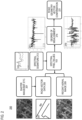
- FIG. 2 is diagram of a process 200 for automatically confirming road geometry based on spectral pixel values of a road link extracted from aerial image(s), according to one embodiment.
- road vector data 205 can be extracted from raster image/map data, etc. 201.
- a road link diagram 207 (depicting the road link 101 based on the road vector data 205) can be generated from a raster image 203.
- Common road extraction algorithms can be classification-based, knowledge-based, mathematical morphology, active contour model, and dynamic programming, etc.
- Such raster image can be retrieved from a remote sensing image library.
- Remote sensing e.g., from satellite or aircraft
- Remote sensing can detect and monitor the physical characteristics of an area by measuring its reflected and emitted radiation at a distance.
- remotely sensed data such as aerial photography, satellite images, LiDAR, radar, unmanned aerial systems (UAS), thermal imagery, hyperspectral data, etc.
- USGS Global Visualization Viewer
- GPS Global Visualization Viewer
- Raster images are pixel-based and contain color and tonal information of the image.
- Examples of raster image file types are: BMP, TIFF, GIF, PNG, and JPEG files.
- the raster image 203 depicts a main road, a small road, several houses and tree blocks, grass blocks, and other areas.
- the road link diagram 207 can be extracted from a raster map, i.e., an electronic map image made up of a set number of pixels.
- Vector data can display latitude and longitude using lines, splines, points, polygons, etc. to describe the topology.
- the road vector data 205 e.g., of the road line 101
- the road vector data 205 can be spatial data in a format consisting of points, lines, splines, and/or polygons.
- the road vector data 205 can comprise sequential points or vertices stored as coordinate pairs that indicate the road link 101. Each vertex contains x coordinate and a y coordinate. Beside roads, other map features such as administrative borders, linear features, rivers, etc. can be recorded as vector data.
- the system 100 can algorithmically confirm road vector geometry (e.g., expressed in the road vector data 205) with recent aerial image(s) 209, such as the aerial image 211.
- Not confirmed vector data such as those have a deviation over a threshold distance (e.g., 5 meters), require further review/verification, e.g., by human, artificial intelligence, machine learning algorithms, etc.
- FIG. 3A is a diagram 300 depicting spectral signatures of different materials, according to one embodiment. Dry grass is visually different from asphalt and fresh basalt, and its spectral signatures is quite different from the spectral signatures of asphalt and fresh basalt. Although asphalt and fresh basalt appear similar in visible light, they reflect different amounts of infrared light that constitute distinctive parts of their spectral signatures in FIG. 3A .
- the system 100 can use natural-color (also called true-color) spectral pixel values in red, green, and blue channels in aerial images to confirm a road vector geometry. Concurrently or alternatively, the system 100 can use false-color spectral pixel values in wavelength channel(s) outside the visible range in arial images to confirm a road vector geometry.
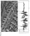
- FIG. 3B are diagrams of spectral pixel values of a vector geometry, according to various embodiment. The top diagram of FIG. 3B is a raster image 301 marked with a vector representation 303 of the road link 101.
- Such vector representation 303 can be represented as a list of spectral pixel values in R, B, G channels/bands in a spectral profile diagram 307 which provide a fingerprint-like representation of the road link 101.
- the spectral values of a gray asphalt road surface of the road link 101 for each band are quite homogeneous (e.g., varying between 145 and 160 for each band), except a drop 309 (e.g., a darker value corresponding to a powerline) at a location 305 of the vector representation 303.
- the spectral feature signature of one material typically maintains a higher correlation value among the RGB bands/channels, which points to a higher confidence of alignment.
- the system 100 can set a pre-determined threshold value on that correlation and/or a confidence indicator value for confirming the road vector geometry or raising a flag for review.
- FIG. 3C is a diagram of an example grid, according to one embodiment. However, as shown in FIG. 3C , it is not as intuitive to draw a line in a raster image between two pixels of a grid 310: (1, 1) at the top left end of the line and (11, 5) at the bottom right end of a line 311.
- the system 100 can use a line drawing algorithm (e.g., Bresenham Algorithm) to get a list of pixel values for the line 311: (1, 1), (2, 1), (3, 2), (4, 2), (5, 3), (6, 3), (7, 3), (8, 4), (9, 4), (10, 5), (11, 5).
- line drawing algorithms include naive algorithm, Xiaolin Wu's line algorithm, Gupta-Sproull algorithm, etc.
- the system 100 can use the line drawing algorithm to get a list of pixel values from the raster image 301 as the road vector representation 303 for the road link 101.
- FIGs. 3D-3E are diagrams of spectral pixel values of two vector geometry examples, according to various embodiments.
- FIGs. 3D-3E share a recent or latest raster image 320 which covers a bigger area than the raster image 301 in FIG. 3B yet with two vector geometry examples 321 and 331 respectively that were created (e.g., by some map creator application user or as input data set from a source supplier such as a direct crowd-source, OpenStreetMap, a public agency, a commercial source, etc.) and need to be validated/confirmed to ensure the data is correct and up to date.
- a source supplier such as a direct crowd-source, OpenStreetMap, a public agency, a commercial source, etc.
- the spectral profile diagram 217 shows a high degree of alignment, i.e., a high confidence indicator confirming that the vector geometry example 321 is validated as close to the road geometry in the real world (e.g., close to 100% match).
- the vector geometry example 321 a very close match with the actual road segment based on the relatively homogeneous spectral profile in the diagram 217 with minimum outliers/peaks yet overall very low noise.
- the spectral profile diagram 219 shows a low degree of alignment, i.e., a low confidence indicator confirming that the vector geometry example 321 is validated as deviating from the road geometry in the real world.
- the confidence indicator decreases.
- the same road is represented with the slightly shifted vector geometry example 331.
- This vector geometry example 331 intersects with the buildings and grass lands along the road.
- the right portion of the vector geometry example 331 has a high confirmation, whereas the shifted portion of the vector geometry example 331 shows a low confirmation.
- the system 100 can just remove the data and/or initiate further review/verification, e.g., by human, artificial intelligence, machine learning algorithms, etc. Alternatively or concurrently, the system 100 can use the confirmation results to perform statistical analysis and build a quality matrix for the respective road geometry vector data source.
- the system 100 can use statistical information related to the color distribution of vehicles 105a-105n (also collectively referred to as vehicles 105) to ensure road segments occupied with vehicles are properly coded as road elements rather than being disregarded due to the high variations of colors.
- FIG. 3F shows an example aerial image of a road segment occupied by rows of vehicles that lead to an untypical RGB representation (e.g., of a road or vegetation).
- RGB representation e.g., of a road or vegetation.
- Such statistical information related to the vehicle color distribution can be observed from historic aerial images, drive files, etc. of the exact road, roads in the area (e.g., a tile, a zip code, a town, a city, a province, a country, etc.), etc.
- the system 100 can use multiple aerial images to remove noise related to the passing vehicles or moving/temporary elements such as fallen trees/leaves, water, mud, snow, ice, oil spills, traffic cones, temporary road markings/signs, shadows of road furniture, etc.
- the system 100 can use multiple aerial images including image(s) with and without the moving/temporary elements to identify the color distribution of the moving/temporary elements, and then adjust the spectral pixel values as discussed thereby removing the noise caused by the moving/temporary elements.
- aerial images taken at noon time have less shadows, such that the system 100 can use recent or latest aerial images taken during noon time to minimize noise caused by shadows on road segments.
- system 100 can use the spectral pixel values contributed by vehicles to count vehicle numbers in aerial image(s) for traffic data, for cross checking with other sources of traffic data.
- the system 100 can apply the process 200 to automatedly confirm any pre-existing map feature geometry (e.g., other road link geometry such as bike lanes, waterways, etc.) with homogeneous spectral pixel values in aerial images.
- a bike lane is a road link dedicated for bicycles, while a waterway can be a road link for water-based transport.
- FIG. 3G is an aerial image showing bike lanes
- FIG. 3H is an aerial image showing a river (i.e., an example waterway) for the system 100 to apply the process 200 to confirm respective pre-existing map feature geometry.
- system 100 can apply the process 200 to confirm more complicated map elements with polygon representations, such as a roof with two boxes of colors and/or extra patterns via their edges.
- the system 100 can leverage latest technological advances in aerial imagery in higher frequency and accuracy and simply rely on pixel values in the aerial images to confirm the road geometries for mapping in an automated, scalable way without using machine learning models (e.g. supervised learning).
- machine learning models e.g. supervised learning
- the system 100 can determine vector data of the road link 101 by processing sensor data (including vehicle trajectory data) from the vehicles 105 (e.g., standard vehicles, autonomous vehicles, heavily assisted driving (HAD) vehicles, semi-autonomous vehicles, etc.).
- the vehicles 105 include one or more vehicle sensors 107a-107n (also collectively referred to as vehicle sensors 107) (e.g., positioning sensors) and have connectivity to a mapping platform 109 via a communication network 111.
- the sensor data includes probe data may be reported as probe points, which are individual data records collected at a point in time that records telemetry data for that point in time.
- a probe point can include attributes such as: (1) probe ID, (2) longitude, (3) latitude, (4) elevation, (5) heading, (6) speed, and (7) time.
- attributes such as: (1) probe ID, (2) longitude, (3) latitude, (4) elevation, (5) heading, (6) speed, and (7) time.
- the list of attributes is provided by way of illustration and not limitation. For example, attributes such as tilt, steering angle, wiper activation, etc. can be included and reported for a probe point.
- the vehicles 105 may include vehicle sensors 107 for reporting measuring and/or reporting attributes.
- the attributes can also be any attribute normally collected by an on-board diagnostic (OBD) system of the vehicle 105, and available through an interface to the OBD system (e.g., OBD II interface or other similar interface).
- OBD on-board diagnostic
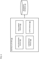
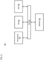
- FIG. 4 is a diagram of the components of the mapping platform 109, according to one embodiment.
- the mapping platform 109 includes one or more components for confirming road vector geometry based on aerial image(s), according to the various embodiments described herein. It is contemplated that the functions of these components may be combined or performed by other components of equivalent functionality.
- the mapping platform 109 includes a data processing module 401, a misalignment module 403, a confirmation module 405, and an output module 407, and has connectivity to the geographic database 123.
- the above presented modules and components of the mapping platform 109 can be implemented in hardware, firmware, software, or a combination thereof. Though depicted as a separate entity in FIG.
- mapping platform 109 may be implemented as a module of any other component of the system 100.
- the mapping platform 109 and/or the modules 401-407 may be implemented as a cloud-based service, local service, native application, or combination thereof.
- the functions of the mapping platform 109, the modules 401-407, and/or edge devices (e.g., UEs 113) are discussed with respect to FIGs. 2-6 .
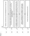
- FIG. 5 is a flowchart of a process for confirming road vector geometry based on aerial image(s), according to one embodiment.
- the mapping platform 109, and/or any of the modules 401-407 may perform one or more portions of the process 500 and may be implemented in, for instance, a chip set including a processor and a memory as shown in FIG. 9 .
- the mapping platform 109, and/or the modules 401-407 can provide means for accomplishing various parts of the process 500, as well as means for accomplishing embodiments of other processes described herein in conjunction with other components of the system 100.
- the process 500 is illustrated and described as a sequence of steps, its contemplated that various embodiments of the process 500 may be performed in any order or combination and need not include all the illustrated steps.
- the data processing module 401 can retrieve a feature and a vector representation (e.g., the vector geometry example 321 in FIG. 3D , the vector geometry example 331 in FIG. 3E ) of a road link (e.g., associated with a roadway, a waterway, or a bike lane).
- a vector representation e.g., the vector geometry example 321 in FIG. 3D , the vector geometry example 331 in FIG. 3E
- a road link e.g., associated with a roadway, a waterway, or a bike lane.
- the data processing module 401 can process one or more aerial images (e.g., the raster image 211 in FIG. 2 ) depicting the road link (e.g., the road link 101) to extract a list of spectral pixel values (e.g., the spectral pixel values 103) corresponding to the vector representation of the road link. For instance, the data processing module 401 can extract a list of pixels in the one or more aerial images based on the vector representation of the road link and a line-drawing algorithm (e.g., Bresenham Algorithm), and the list of spectral pixel values are associated with the list of pixels.
- a line-drawing algorithm e.g., Bresenham Algorithm
- the misalignment module 403 can determine a degree of misalignment (e.g., the degree of misalignment 215) between the spectral pixel values (e.g., the spectral profile in the diagram 217 in FIG. 3D , the spectral profile in the diagram 219 in FIG. 3E , etc.) and a spectral signature (e.g., asphalt, tarmac, concrete, or other road surface materials) of the feature of the road link (e.g., the spectral signature 213in FIG. 2A, the spectral signatures in FIG. 3A ).
- the vector representation can be retrieved from digital map data of a geographic database (e.g., the geographic database 123).
- the confirmation module 405 can initiate a confirmation of a geometry of the vector representation (e.g., the vector geometry example 321 in FIG. 3D ) based on the degree of misalignment (e.g., of the corresponding spectral pixel data in R, G, B bands in the spectral profile in FIG. 3D ).
- the confirmation module 405 can compute a confidence indicator (e.g., almost 100% in FIG. 3D ) based on the degree of misalignment, and the confirmation of the geometry of the vector representation can be based on the confidence indicator. For instance, the confidence indicator decreases as the degree of misalignment increases. As shown in FIG.
- the spectral feature signature of one uniform material typically maintains a higher correlation value among the RGB bands/channels, that leads to a higher confidence of alignment.
- the system 100 can set a pre-determined threshold value based on experiments for the correlation and/or the confidence indicator thereby confirming the road vector geometry or raising a flag for review the road vector geometry.
- the data processing module 401 can process the one or more aerial images (e.g., similar to the roaster image in FIG. 3F ) to determine a color distribution of a plurality vehicles depicted in the one or more aerial images, and adjust the extracting of the list of spectral pixel values is based on the color distribution (e.g., with a lot of white cars). For instance, the adjusting of the extracting of the list of spectral pixel values can be based on determining that a spectral pixel value variation of the fingerprint-like representation is greater than a threshold variation (e.g., 150).
- a threshold variation e.g. 150
- the data processing module 401 can tolerate certain variations in the spectral profile for portion(s) of the road link corresponding to lengths of colored objects commonly found on the road (e.g. vehicles, road markings, etc.). In this case, the data processing module 401 can set a minimum length of a continuous spectral pixel value signature profile as a condition to determine whether the extracted information is useful to confirm a road vector geometry. Referring back to FIG. 3F , when the road link is occupied by too many vehicles and road markings to reveal sufficient road surface, the data processing module 401 cannot find a minimum length of a continuous spectral pixel value signature profile for the road link such that the aerial image in FIG. 3F is not suitable for the process 200.
- the data processing module 401 can process the one or more aerial images to determine spectral pixel variation data corresponding to one or more objects (e.g., fallen trees/leaves, water, mud, snow, ice, oil spills, traffic cones, temporary road markings/signs, shadows of road furniture, etc.) on the road link, and exclude one or more object spectral pixel values corresponding to the one or more objects from the list spectral pixel values before determining the degree of misalignment.
- the data processing module 401 can code an object type of the one or more objects based on the spectral pixel variation data, and the one or more object spectral pixel values can be excluded from the list of spectral pixel values based on the object type.
- the data processing module 401 can select the one or more aerial images based on traffic information associated with the road link. For instance, the data processing module 401 can select aerial images taken at noon time have less shadows, and/or during no or low vehicle traffic (e.g., early morning), to avoid noise caused by vehicles on road segments, etc.
- the system 100 can set one or more parameters for selecting the aerial images such as a minimum correlation value for channels (e.g., "65%”), a target color/spectral signature (for calculating a deviation from a target feature, such as "asphalt"), a maximum tolerance distance for objects on the road (e.g., "4.5 meters” for a car), an image capturing timing (e.g., "noon time” to avoid shadows), a maximum tolerance number of objects on the road (e.g., "60” vehicles for a 50-meter highway segment), etc.
- the output module 407 can providing the confirmation as an output. FIGs.
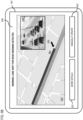
- FIG. 6A-6B are diagrams of example user interfaces of monitoring and/or flagging road vector data, according to various embodiments.
- FIG. 6A is a diagram of a user interface associated with monitoring road vector data, according to example embodiment(s).
- the UI 601 may be generated for the UE 115 that depicts a bar chart 603 and a data source quality scale 605 as results of a confirmation analysis based on the above-discussed embodiments.
- the UI 601 further shows a confirmation analysis setting panel 607 that includes an upload vector data source menu 609, a plurality of data source switches 611, an aerial image parameter menu 613, and an input 615 of "Confirmation Analysis.”
- the data source switches 611 include direct crowd-sources 611a, OpenStreetMap 611b, agency-generated 611c, commercial source A 61 1d, commercial source B 61 1e, commercial source C 611f, etc.
- the direct crowd-sources 611a is switched on and the above-mentioned example aerial image parameters are selected by a user (e.g., a map service provider, a city planner, a pedestrian, a driver, a passenger, etc. with different levels of data access based on credentials), and the user further selects the input 615 of "Confirmation Analysis".
- a user e.g., a map service provider, a city planner, a pedestrian, a driver, a passenger, etc. with different levels of data access based on credentials
- the user can be a human.
- the selection of the mentioned options can be performed by artificial intelligence via an application programming interface (API) without involving users or UIs, for automated submission of road links for review based on updated imagery.
- API application programming interface
- the user interface 621 in FIG. 6B (e.g., a navigation application 115) is generated for a UE 113 (e.g., a mobile device, an embedded navigation system, a client terminal, etc.).
- the user interface 621 in FIG. 6B shows a map 623, an arrow 625 pointing towards a road link flagged for review (e.g., a lane shift caused by road widening detected on a road segment 627 in the map 623 based on the color difference between old and new road pavements reflected in the spectral profiles of the different road segments as discussed, and an alert 629: "Warning!
- the user interface 621 also shows a "More Details” button 631 and a “ Manually Update” button 633.
- a user can interact with the user interfaces via one or more physical interactions (e.g., a touch, a tap, a gesture, typing, etc.), one or more voice commands (e.g., "review the flagged road link for geometry” "update the flagged road link with a new attribute,” etc.), or a combination thereof.
- the user interface 621 shows a live traffic image 635.
- the user can then proceed with manually updating the road geometry change and/or the lane shift incident into the map database by selecting the "Manually Update” button 633.
- the system 100 can prompt the user to confirm the road geometry change and/or the lane shift incident determined by the system 100 to update the map database accordingly without further user intervention. This is particularly true in the case of a user that is a passenger in an autonomous vehicle. It is contemplated that the system 100 can determine or detect one or more actions by a user (e.g., an eye gaze) and automatically confirm the road geometry change and/or the road incident and update the map database accordingly.
- a user e.g., an eye gaze
- the content providers 121 may also store content associated with the mapping platform 109, the services platform 117, the services 119, the geographic database 123, and/or the vehicles 105. In another embodiment, the content providers 121 may manage access to a central repository of data, and offer a consistent, standard interface to data, and/or the geographic database 123.
- the UEs 113 are any type of embedded system, mobile terminal, fixed terminal, or portable terminal including a built-in navigation system, a personal navigation device, mobile handset, station, unit, device, multimedia computer, multimedia tablet, Internet node, communicator, desktop computer, laptop computer, notebook computer, netbook computer, tablet computer, personal communication system (PCS) device, personal digital assistants (PDAs), audio/video player, digital camera/camcorder, positioning device, fitness device, television receiver, radio broadcast receiver, electronic book device, game device, or any combination thereof, including the accessories and peripherals of these devices, or any combination thereof. It is also contemplated that a UE 113 can support any type of interface to the user (such as "wearable" circuitry, etc.).
- a UE 113 may be associated with a vehicle 105 (e.g., a mobile device) or be a component part of the vehicle 105 (e.g., an embedded navigation system).
- the UEs 113 may include the mapping platform 109 to confirm road vector geometry based on aerial image(s).
- the probe points can be reported from the vehicles 105 in real-time, in batches, continuously, or at any other frequency requested by the system 100 over, for instance, the communication network 111 for processing by the mapping platform 109.
- the probe points also can be map matched to specific road links stored in the geographic database 123.
- the system 100 e.g., via the mapping platform 109) generates vehicle paths or trajectories from the observed and expected frequency of probe points for an individual probe as discussed with respect to the various embodiments described herein so that the probe traces represent a travel trajectory or vehicle path of the probe through the road network.
- the vehicles 105 are configured with various sensors (e.g., vehicle sensors 107) for generating or collecting probe data, sensor data, related geographic/map data, etc.
- the sensed data represents sensor data associated with a geographic location or coordinates at which the sensor data was collected (e.g., a latitude and longitude pair).
- the probe data (e.g., stored in the geographic database 123) includes location probes collected by one or more vehicle sensors 107.
- the vehicle sensors 107 may include a RADAR system, a LiDAR system, global positioning sensor for gathering location data (e.g., GPS), a network detection sensor for detecting wireless signals or receivers for different short-range communications (e.g., Bluetooth, Wi-Fi, Li-Fi, near field communication (NFC) etc.), temporal information sensors, a camera/imaging sensor for gathering image data, an audio recorder for gathering audio data, velocity sensors mounted on a steering wheel of the vehicles 105, switch sensors for determining whether one or more vehicle switches are engaged, and the like.
- a RADAR system e.g., a LiDAR system
- global positioning sensor for gathering location data
- a network detection sensor for detecting wireless signals or receivers for different short-range communications
- NFC near field communication
- the vehicles 105 can be any type of vehicle manned or unmanned (e.g., cars, trucks, buses, vans, motorcycles, scooters, drones, etc.) that travels through road links of a road network.
- vehicle manned or unmanned e.g., cars, trucks, buses, vans, motorcycles, scooters, drones, etc.
- sensors 107 of a vehicle 105 may include light sensors, orientation sensors augmented with height sensors and acceleration sensor (e.g., an accelerometer can measure acceleration and can be used to determine orientation of the vehicle), tilt sensors to detect the degree of incline or decline of a vehicle 105 along a path of travel, moisture sensors, pressure sensors, etc.
- vehicle sensors 107 about the perimeter of a vehicle 105 may detect the relative distance of the vehicle 105 from a physical divider, a lane line of a link or roadway, the presence of other vehicles, pedestrians, traffic lights, potholes and any other objects, or a combination thereof.
- the vehicle sensors 107 may detect weather data, traffic information, or a combination thereof.
- the UEs 113 may also be configured with various sensors (not shown for illustrative convenience) for acquiring and/or generating probe data and/or sensor data associated with a vehicle 105, a driver, a passenger, other vehicles, conditions regarding the driving environment or roadway, etc.
- sensors may be used as GPS receivers for interacting with the one or more satellites 125 to determine and track the current speed, position, and location of a vehicle 105 travelling along a link or road link.
- the sensors may gather tilt data (e.g., a degree of incline or decline of the vehicle during travel), motion data, light data, sound data, image data, weather data, temporal data and other data associated with the vehicles 105 and/or UEs 113.
- the sensors may detect local or transient network and/or wireless signals, such as those transmitted by nearby devices during navigation of a vehicle along a roadway (Li-Fi, near field communication (NFC)) etc.
- the mapping platform 109 retrieves aggregated probe points gathered and/or generated by the vehicle sensors 107 and/or the UEs 113 resulting from the travel of the UEs 113 and/or vehicles 105 on a road link of a road network.
- the geographic database 123 stores a plurality of probe points and/or trajectories generated by different vehicle sensors 107, UEs 113, applications 115, vehicles 105, etc. over a period while traveling in a large, monitored area (e.g., a stretch of roadway where a closure incident is reported).
- a time sequence of probe points specifies a trajectory-i.e., a path traversed by a UE 113, application 115, vehicle 105, etc. over the period. In one instance, as the time between data points increases, so does the distance and the possible routes/paths between those two points.
- the communication network 111 of the system 100 includes one or more networks such as a data network, a wireless network, a telephony network, or any combination thereof.
- the data network may be any local area network (LAN), metropolitan area network (MAN), wide area network (WAN), a public data network (e.g., the Internet), short range wireless network, or any other suitable packet-switched network, such as a commercially owned, proprietary packet-switched network, e.g., a proprietary cable or fiberoptic network, and the like, or any combination thereof.
- a protocol includes a set of rules defining how the network nodes within the communication network 111 interact with each other based on information sent over the communication links.
- the protocols are effective at different layers of operation within each node, from generating and receiving physical signals of various types, to selecting a link for transferring those signals, to the format of information indicated by those signals, to identifying which software application executing on a computer system sends or receives the information.
- the conceptually different layers of protocols for exchanging information over a network are described in the Open Systems Interconnection (OSI) Reference Model.
- the higher layer protocol is said to be encapsulated in the lower layer protocol.
- the headers included in a packet traversing multiple heterogeneous networks, such as the Internet typically include a physical (layer 1) header, a data-link (layer 2) header, an internetwork (layer 3) header and a transport (layer 4) header, and various application (layer 5, layer 6 and layer 7) headers as defined by the OSI Reference Model.
- geographic features are represented using polygons (e.g., two-dimensional features) or polygon extrusions (e.g., three-dimensional features).
- polygons e.g., two-dimensional features
- polygon extrusions e.g., three-dimensional features
- the edges of the polygons correspond to the boundaries or edges of the respective geographic feature.
- a two-dimensional polygon can be used to represent a footprint of the building
- a three-dimensional polygon extrusion can be used to represent the three-dimensional surfaces of the building.
- Node A point that terminates a link.
- Link (or “edge”) - A contiguous, non-branching string of one or more line segments terminating in a node at each end.
- link can be a straight line, a spline, etc.
- Shape point A point along a link between two nodes (e.g., used to alter a shape of the link without defining new nodes).
- Oriented link A link that has a starting node (referred to as the “reference node”) and an ending node (referred to as the “non reference node”).
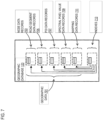
- the geographic database 123 includes node data records 703, road link or link data records 705, POI data records 707, spectral pixel value data records 709, mapping data records 711, and indexes 713, for example. More, fewer or different data records can be provided. In one embodiment, additional data records (not shown) can include cartographic ("carto") data records, routing data, and maneuver data. In one embodiment, the indexes 713 may improve the speed of data retrieval operations in the geographic database 123. In one embodiment, the indexes 713 may be used to quickly locate data without having to search every row in the geographic database 123 every time it is accessed. For example, in one embodiment, the indexes 713 can be a spatial index of the polygon points associated with stored feature polygons.
- the road/link segments and nodes can be associated with attributes, such as geographic coordinates, street names, address ranges, speed limits, turn restrictions at intersections, and other navigation related attributes, as well as POIs, such as gasoline stations, hotels, restaurants, museums, stadiums, offices, automobile dealerships, auto repair shops, buildings, stores, parks, etc.
- the geographic database 123 can include data about the POIs and their respective locations in the POI data records 707.
- the geographic database 123 can also include data about places, such as cities, towns, or other communities, and other geographic features, such as bodies of water, mountain ranges, etc.
- Such place or feature data can be part of the POI data records 707 or can be associated with POIs or POI data records 707 (such as a data point used for displaying or representing a position of a city).
- certain attributes such as lane marking data records, mapping data records and/or other attributes can be features or layers associated with the link-node structure of the database.
- the geographic database 123 can also include the spectral pixel value data records 709 for storing spectral pixel value data records, spectral profile data, road geometry data, misalignment data, confirmation data, map element color distribution data, training data, prediction models, annotated observations, computed featured distributions, sampling probabilities, and/or any other data generated or used by the system 100 according to the various embodiments described herein.
- the spectral pixel value data records 709 can be associated with one or more of the node records 703, road link records 705, and/or POI data records 707 to support localization or visual odometry based on the features stored therein and the corresponding estimated quality of the features.
- the records 709 can also be associated with or used to classify the characteristics or metadata of the corresponding records 703, 705, and/or 707.
- the mapping data records 711 model road surfaces and other map features to centimeter-level or better accuracy.
- the mapping data records 711 also include lane models that provide the precise lane geometry with lane boundaries, as well as rich attributes of the lane models. These rich attributes include, but are not limited to, lane traversal information, lane types, lane marking types, lane level speed limit information, and/or the like.
- the mapping data records 711 are divided into spatial partitions of varying sizes to provide mapping data to vehicles 105 and other end user devices with near real-time speed without overloading the available resources of the vehicles 105 and/or devices (e.g., computational, memory, bandwidth, etc. resources).
- mapping data records 711 are created from high-resolution 3D mesh or point-cloud data generated, for instance, from LiDAR-equipped vehicles.
- the 3D mesh or point-cloud data are processed to create 3D representations of a street or geographic environment at centimeter-level accuracy for storage in the mapping data records 711.
- the mapping data records 711 also include real-time sensor data collected from probe vehicles in the field.
- the real-time sensor data for instance, integrates real-time traffic information, weather, and road conditions (e.g., potholes, road friction, road wear, etc.) with highly detailed 3D representations of street and geographic features to provide precise real-time also at centimeter-level accuracy.
- Other sensor data can include vehicle telemetry or operational data such as windshield wiper activation state, braking state, steering angle, accelerator position, and/or the like.
- the geographic database 123 can be maintained by the content provider 119 in association with the services platform 117 (e.g., a map developer).
- the map developer can collect geographic data to generate and enhance the geographic database 123.
- the map developer can employ field personnel to travel by vehicle (e.g., vehicles 105 and/or UEs 113) along roads throughout the geographic region to observe features and/or record information about them, for example.
- remote sensing such as aerial or satellite photography, can be used.
- the geographic database 123 can be a master geographic database stored in a format that facilitates updating, maintenance, and development.
- the master geographic database or data in the master geographic database can be in an Oracle spatial format or other spatial format, such as for development or production purposes.
- the Oracle spatial format or development/production database can be compiled into a delivery format, such as a geographic data files (GDF) format.
- GDF geographic data files
- the data in the production and/or delivery formats can be compiled or further compiled to form geographic database products or databases, which can be used in end user navigation devices or systems.
- geographic data is compiled (such as into a platform specification format (PSF) format) to organize and/or configure the data for performing navigation-related functions and/or services, such as route calculation, route guidance, map display, speed calculation, distance and travel time functions, and other functions, by a navigation device, such as by a vehicle 105 or a UE 113, for example.
- the navigation-related functions can correspond to vehicle navigation, pedestrian navigation, or other types of navigation.
- the compilation to produce the end user databases can be performed by a party or entity separate from the map developer. For example, a customer of the map developer, such as a navigation device developer or other end user device developer, can perform compilation on a received geographic database in a delivery format to produce one or more compiled navigation databases.
- a superposition of multiple simultaneous quantum states before measurement represents a quantum bit (qubit).
- a sequence of one or more digits constitutes digital data that is used to represent a number or code for a character.
- information called analog data is represented by a near continuum of measurable values within a particular range.
- the set of operations also typically include comparing two or more units of information, shifting positions of units of information, and combining two or more units of information, such as by addition or multiplication or logical operations like OR, exclusive OR (XOR), and AND.
- Each operation of the set of operations that can be performed by the processor is represented to the processor by information called instructions, such as an operation code of one or more digits.
- a sequence of operations to be executed by the processor 802, such as a sequence of operation codes, constitute processor instructions, also called computer system instructions or, simply, computer instructions.
- Processors may be implemented as mechanical, electrical, magnetic, optical, chemical or quantum components, among others, alone or in combination.
- Information including instructions for confirming road vector geometry based on aerial image(s), is provided to the bus 810 for use by the processor from an external input device 812, such as a keyboard containing alphanumeric keys operated by a human user, or a sensor.
- an external input device 812 such as a keyboard containing alphanumeric keys operated by a human user, or a sensor.
- a sensor detects conditions in its vicinity and transforms those detections into physical expression compatible with the measurable phenomenon used to represent information in computer system 800.
- Other external devices coupled to bus 810 used primarily for interacting with humans, include a display device 814, such as a cathode ray tube (CRT) or a liquid crystal display (LCD), or plasma screen or printer for presenting text or images, and a pointing device 816, such as a mouse or a trackball or cursor direction keys, or motion sensor, for controlling a position of a small cursor image presented on the display 814 and issuing commands associated with graphical elements presented on the display 814.
- a display device 814 such as a cathode ray tube (CRT) or a liquid crystal display (LCD), or plasma screen or printer for presenting text or images
- a pointing device 816 such as a mouse or a trackball or cursor direction keys, or motion sensor, for controlling a position of a small cursor image presented on the display 814 and issuing commands associated with graphical elements presented on the display 814.
- a display device 814 such as a cathode ray tube (CRT
- special purpose hardware such as an application specific integrated circuit (ASIC) 820, is coupled to bus 810.
- the special purpose hardware is configured to perform operations not performed by processor 802 quickly enough for special purposes.
- application specific ICs include graphics accelerator cards for generating images for display 814, cryptographic boards for encrypting and decrypting messages sent over a network, speech recognition, and interfaces to special external devices, such as robotic arms and medical scanning equipment that repeatedly perform some complex sequence of operations that are more efficiently implemented in hardware.
- Computer system 800 also includes one or more instances of a communications interface 870 coupled to bus 810.
- Communication interface 870 provides a one-way or two-way communication coupling to a variety of external devices that operate with their own processors, such as printers, scanners and external disks. In general the coupling is with a network link 878 that is connected to a local network 880 to which a variety of external devices with their own processors are connected.
- communication interface 870 may be a parallel port or a serial port or a universal serial bus (USB) port on a personal computer.
- USB universal serial bus
- communications interface 870 is an integrated services digital network (ISDN) card or a digital subscriber line (DSL) card or a telephone modem that provides an information communication connection to a corresponding type of telephone line.
- ISDN integrated services digital network
- DSL digital subscriber line
- a communication interface 870 is a cable modem that converts signals on bus 810 into signals for a communication connection over a coaxial cable or into optical signals for a communication connection over a fiber optic cable.
- communications interface 870 may be a local area network (LAN) card to provide a data communication connection to a compatible LAN, such as Ethernet. Wireless links may also be implemented.
- LAN local area network
- the communications interface 870 sends or receives or both sends and receives electrical, acoustic or electromagnetic signals, including infrared and optical signals, that carry information streams, such as digital data.
- the communications interface 870 includes a radio band electromagnetic transmitter and receiver called a radio transceiver.
- the communications interface 870 enables connection to the communication network 111 for confirming road vector geometry based on aerial image(s).
- Non-volatile media include, for example, optical or magnetic disks, such as storage device 808.
- Volatile media include, for example, dynamic memory 804.
- Transmission media include, for example, coaxial cables, copper wire, fiber optic cables, and carrier waves that travel through space without wires or cables, such as acoustic waves and electromagnetic waves, including radio, optical and infrared waves. Signals include man-made transient variations in amplitude, frequency, phase, polarization or other physical properties transmitted through the transmission media.
- Computer-readable media include, for example, a floppy disk, a flexible disk, hard disk, magnetic tape, any other magnetic medium, a CD-ROM, CDRW, DVD, any other optical medium, punch cards, paper tape, optical mark sheets, any other physical medium with patterns of holes or other optically recognizable indicia, a RAM, a PROM, an EPROM, a FLASH-EPROM, any other memory chip or cartridge, a carrier wave, or any other medium from which a computer can read.
- a floppy disk a flexible disk, hard disk, magnetic tape, any other magnetic medium, a CD-ROM, CDRW, DVD, any other optical medium, punch cards, paper tape, optical mark sheets, any other physical medium with patterns of holes or other optically recognizable indicia, a RAM, a PROM, an EPROM, a FLASH-EPROM, any other memory chip or cartridge, a carrier wave, or any other medium from which a computer can read.
- Network link 878 typically provides information communication using transmission media through one or more networks to other devices that use or process the information.
- network link 878 may provide a connection through local network 880 to a host computer 882 or to equipment 884 operated by an Internet Service Provider (ISP).
- ISP equipment 884 in turn provides data communication services through the public, world-wide packet-switching communication network of networks now commonly referred to as the Internet 890.
- a computer called a server host 892 connected to the Internet hosts a process that provides a service in response to information received over the Internet.
- server host 892 hosts a process that provides information representing video data for presentation at display 814. It is contemplated that the components of system can be deployed in various configurations within other computer systems, e.g., host 882 and server 892.
- FIG. 9 illustrates a chip set 900 upon which an embodiment of the invention may be implemented.
- Chip set 900 is programmed to confirm road vector geometry based on aerial image(s) as described herein and includes, for instance, the processor and memory components described with respect to FIG. 8 incorporated in one or more physical packages (e.g., chips).
- a physical package includes an arrangement of one or more materials, components, and/or wires on a structural assembly (e.g., a baseboard) to provide one or more characteristics such as physical strength, conservation of size, and/or limitation of electrical interaction. It is contemplated that in certain embodiments the chip set can be implemented in a single chip.
- the chip set 900 includes a communication mechanism such as a bus 901 for passing information among the components of the chip set 900.
- a processor 903 has connectivity to the bus 901 to execute instructions and process information stored in, for example, a memory 905.
- the processor 903 may include one or more processing cores with each core configured to perform independently.
- a multi-core processor enables multiprocessing within a single physical package. Examples of a multi-core processor include two, four, eight, or greater numbers of processing cores.
- the processor 903 may include one or more microprocessors configured in tandem via the bus 901 to enable independent execution of instructions, pipelining, and multithreading.
- the processor 903 may also be accompanied with one or more specialized components to perform certain processing functions and tasks such as one or more digital signal processors (DSP) 907, or one or more application-specific integrated circuits (ASIC) 909.
- DSP digital signal processors
- ASIC application-specific integrated circuits
- a DSP 907 typically is configured to process real-world signals (e.g., sound) in real time independently of the processor 903.
- an ASIC 909 can be configured to performed specialized functions not easily performed by a general purposed processor.
- Other specialized components to aid in performing the inventive functions described herein include one or more field programmable gate arrays (FPGA) (not shown), one or more controllers (not shown), or one or more other special-purpose computer chips.
- FPGA field programmable gate arrays
- the processor 903 and accompanying components have connectivity to the memory 905 via the bus 901.
- the memory 905 includes both dynamic memory (e.g., RAM, magnetic disk, writable optical disk, etc.) and static memory (e.g., ROM, CD-ROM, etc.) for storing executable instructions that when executed perform the inventive steps described herein to confirm road vector geometry based on aerial image(s).
- the memory 905 also stores the data associated with or generated by the execution of the inventive steps.
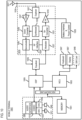
- FIG. 10 is a diagram of exemplary components of a mobile terminal 1001 (e.g., handset or vehicle or part thereof) capable of operating in the system of FIG. 1 , according to example embodiment(s).
- a radio receiver is often defined in terms of front-end and back-end characteristics.
- the front-end of the receiver encompasses all of the Radio Frequency (RF) circuitry whereas the back-end encompasses all of the base-band processing circuitry.
- Pertinent internal components of the telephone include a Main Control Unit (MCU) 1003, a Digital Signal Processor (DSP) 1005, and a receiver/transmitter unit including a microphone gain control unit and a speaker gain control unit.
- MCU Main Control Unit
- DSP Digital Signal Processor
- a main display unit 1007 provides a display to the user in support of various applications and mobile station functions that offer automatic contact matching.
- An audio function circuitry 1009 includes a microphone 1011 and microphone amplifier that amplifies the speech signal output from the microphone 1011. The amplified speech signal output from the microphone 1011 is fed to a coder/decoder (CODEC) 1013.
- CDDEC coder/decoder
- a user of mobile station 1001 speaks into the microphone 1011 and his or her voice along with any detected background noise is converted into an analog voltage.
- the analog voltage is then converted into a digital signal through the Analog to Digital Converter (ADC) 1023.
- ADC Analog to Digital Converter
- the control unit 1003 routes the digital signal into the DSP 1005 for processing therein, such as speech encoding, channel encoding, encrypting, and interleaving.
- the processed voice signals are encoded, by units not separately shown, using a cellular transmission protocol such as global evolution (EDGE), general packet radio service (GPRS), global system for mobile communications (GSM), Internet protocol multimedia subsystem (IMS), universal mobile telecommunications system (UMTS), etc., as well as any other suitable wireless medium, e.g., microwave access (WiMAX), Long Term Evolution (LTE) networks, code division multiple access (CDMA), wireless fidelity (WiFi), satellite, and the like.
- a cellular transmission protocol such as global evolution (EDGE), general packet radio service (GPRS), global system for mobile communications (GSM), Internet protocol multimedia subsystem (IMS), universal mobile telecommunications system (UMTS), etc.
- EDGE global evolution
- GPRS general packet radio service
- GSM global system for mobile communications
- IMS Internet protocol multimedia subsystem
- UMTS universal mobile telecommunications system
- any other suitable wireless medium e.g., microwave access (WiMAX), Long Term Evolution (LTE)
- the encoded signals are then routed to an equalizer 1025 for compensation of any frequency-dependent impairments that occur during transmission though the air such as phase and amplitude distortion.
- the modulator 1027 combines the signal with a RF signal generated in the RF interface 1029.
- the modulator 1027 generates a sine wave by way of frequency or phase modulation.
- an upconverter 1031 combines the sine wave output from the modulator 1027 with another sine wave generated by a synthesizer 1033 to achieve the desired frequency of transmission.
- the signal is then sent through a PA 1019 to increase the signal to an appropriate power level.
- the PA 1019 acts as a variable gain amplifier whose gain is controlled by the DSP 1005 from information received from a network base station.
- the signal is then filtered within the duplexer 1021 and optionally sent to an antenna coupler 1035 to match impedances to provide maximum power transfer. Finally, the signal is transmitted via antenna 1017 to a local base station.
- An automatic gain control (AGC) can be supplied to control the gain of the final stages of the receiver.
- the signals may be forwarded from there to a remote telephone which may be another cellular telephone, other mobile phone or a land-line connected to a Public Switched Telephone Network (PSTN), or other telephony networks.
- PSTN Public Switched Telephone Network
- the MCU 1003 receives various signals including input signals from the keyboard 1047.
- the keyboard 1047 and/or the MCU 1003 in combination with other user input components (e.g., the microphone 1011) comprise a user interface circuitry for managing user input.
- the MCU 1003 runs a user interface software to facilitate user control of at least some functions of the mobile station 1001 to confirm road vector geometry based on aerial image(s).
- the MCU 1003 also delivers a display command and a switch command to the display 1007 and to the speech output switching controller, respectively.
- the MCU 1003 exchanges information with the DSP 1005 and can access an optionally incorporated SIM card 1049 and a memory 1051.
- the MCU 1003 executes various control functions required of the station.
- the DSP 1005 may, depending upon the implementation, perform any of a variety of conventional digital processing functions on the voice signals. Additionally, DSP 1005 determines the background noise level of the local environment from the signals detected by microphone 1011 and sets the gain of microphone 1011 to a level selected to compensate for the natural tendency of the user of the mobile station 1001.
- the CODEC 1013 includes the ADC 1023 and DAC 1043.
- the memory 1051 stores various data including call incoming tone data and is capable of storing other data including music data received via, e.g., the global Internet.
- the software module could reside in RAM memory, flash memory, registers, or any other form of writable computer-readable storage medium known in the art including non-transitory computer-readable storage medium.
- the memory device 1051 may be, but not limited to, a single memory, CD, DVD, ROM, RAM, EEPROM, optical storage, or any other non-volatile or non-transitory storage medium capable of storing digital data.
- An optionally incorporated SIM card 1049 carries, for instance, important information, such as the cellular phone number, the carrier supplying service, subscription details, and security information.
- the SIM card 1049 serves primarily to identify the mobile station 1001 on a radio network.
- the card 1049 also contains a memory for storing a personal telephone number registry, text messages, and user specific mobile station settings.
Landscapes
- Engineering & Computer Science (AREA)
- Physics & Mathematics (AREA)
- General Physics & Mathematics (AREA)
- Multimedia (AREA)
- Theoretical Computer Science (AREA)
- Remote Sensing (AREA)
- Computer Vision & Pattern Recognition (AREA)
- Radar, Positioning & Navigation (AREA)
- Artificial Intelligence (AREA)
- Automation & Control Theory (AREA)
- Health & Medical Sciences (AREA)
- Computing Systems (AREA)
- Databases & Information Systems (AREA)
- Evolutionary Computation (AREA)
- General Health & Medical Sciences (AREA)
- Medical Informatics (AREA)
- Software Systems (AREA)
- Processing Or Creating Images (AREA)
- Image Analysis (AREA)
- Traffic Control Systems (AREA)
Applications Claiming Priority (1)
| Application Number | Priority Date | Filing Date | Title |
|---|---|---|---|
| US17/483,422 US11721096B2 (en) | 2021-09-23 | 2021-09-23 | Method, apparatus, and system for confirming road vector geometry based on aerial images |
Publications (2)
| Publication Number | Publication Date |
|---|---|
| EP4155671A1 true EP4155671A1 (de) | 2023-03-29 |
| EP4155671B1 EP4155671B1 (de) | 2026-04-01 |
Family
ID=83439082
Family Applications (1)
| Application Number | Title | Priority Date | Filing Date |
|---|---|---|---|
| EP22197008.0A Active EP4155671B1 (de) | 2021-09-23 | 2022-09-22 | Verfahren, vorrichtung und system zur bestätigung der strassenvektorgeometrie auf der basis von luftbildern |
Country Status (2)
| Country | Link |
|---|---|
| US (1) | US11721096B2 (de) |
| EP (1) | EP4155671B1 (de) |
Families Citing this family (3)
| Publication number | Priority date | Publication date | Assignee | Title |
|---|---|---|---|---|
| US12394073B2 (en) * | 2022-01-24 | 2025-08-19 | Motional Ad Llc | Aligning geodata graph over electronic maps |
| CN121120842A (zh) * | 2025-09-05 | 2025-12-12 | 浙江时空智子大数据有限公司 | 基于多源数据融合多级街区生成方法、系统及电子设备 |
| CN121051183B (zh) * | 2025-10-29 | 2026-03-13 | 青岛市勘察测绘研究院 | 路网提取方法、装置、电子设备及计算机可读存储介质 |
Family Cites Families (11)
| Publication number | Priority date | Publication date | Assignee | Title |
|---|---|---|---|---|
| JP4228745B2 (ja) * | 2003-03-28 | 2009-02-25 | 株式会社日立製作所 | 多スペクトル撮像画像解析装置 |
| US7660441B2 (en) | 2004-07-09 | 2010-02-09 | Southern California, University | System and method for fusing geospatial data |
| JP2007033931A (ja) | 2005-07-27 | 2007-02-08 | Hitachi Software Eng Co Ltd | 衛星画像等を用いた地図作成のための道路認識システム |
| US7869667B1 (en) | 2007-01-19 | 2011-01-11 | Google Inc. | Method for automatic alignment of raster data with vector data in a geographic information system |
| US8731305B1 (en) | 2011-03-09 | 2014-05-20 | Google Inc. | Updating map data using satellite imagery |
| JP5724110B2 (ja) | 2011-07-07 | 2015-05-27 | 株式会社日立製作所 | 経路作成システム、経路作成方法及びプログラム |
| US9395193B2 (en) | 2012-06-10 | 2016-07-19 | Apple Inc. | Scalable and efficient cutting of map tiles |
| US9805276B2 (en) * | 2016-03-31 | 2017-10-31 | Toyota Jidosha Kabushiki Kaisha | Generating real-time driver familiarity index for fine-grained dynamic road scenes |
| US20180321142A1 (en) * | 2017-05-05 | 2018-11-08 | Magna Electronics Inc. | Road surface detection system |
| US11386649B2 (en) * | 2019-11-15 | 2022-07-12 | Maxar Intelligence Inc. | Automated concrete/asphalt detection based on sensor time delay |
| US11941878B2 (en) * | 2021-06-25 | 2024-03-26 | Raytheon Company | Automated computer system and method of road network extraction from remote sensing images using vehicle motion detection to seed spectral classification |
-
2021
- 2021-09-23 US US17/483,422 patent/US11721096B2/en active Active
-
2022
- 2022-09-22 EP EP22197008.0A patent/EP4155671B1/de active Active
Non-Patent Citations (3)
| Title |
|---|
| MACEDO M�RCIA ET AL: "Remote Sensing Applied to the Extraction of Road Geometric Features Based on Optimum Path Forest Classifiers, Northeastern Brazil", vol. 12, no. 01, 1 January 2020 (2020-01-01), pages 15 - 44, XP093020355, ISSN: 2151-1950, Retrieved from the Internet <URL:https://www.scirp.org/journal/doi.aspx?doi=10.4236/jgis.2020.121002> DOI: 10.4236/jgis.2020.121002 * |
| SUKHENDU DAS ET AL: "Use of Salient Features for the Design of a Multistage Framework to Extract Roads From High-Resolution Multispectral Satellite Images", IEEE TRANSACTIONS ON GEOSCIENCE AND REMOTE SENSING, IEEE, USA, vol. 49, no. 10, 1 October 2011 (2011-10-01), pages 3906 - 3931, XP011384196, ISSN: 0196-2892, DOI: 10.1109/TGRS.2011.2136381 * |
| ZHANWU YU ET AL: "A novel two-steps strategy for automatic gis-image registration", IMAGE PROCESSING, 2004. ICIP '04. 2004 INTERNATIONAL CONFERENCE ON SINGAPORE 24-27 OCT. 2004, PISCATAWAY, NJ, USA,IEEE, vol. 3, 24 October 2004 (2004-10-24), pages 1711 - 1714, XP010786090, ISBN: 978-0-7803-8554-2, DOI: 10.1109/ICIP.2004.1421402 * |
Also Published As
| Publication number | Publication date |
|---|---|
| US11721096B2 (en) | 2023-08-08 |
| EP4155671B1 (de) | 2026-04-01 |
| US20230086235A1 (en) | 2023-03-23 |
Similar Documents
| Publication | Publication Date | Title |
|---|---|---|
| US12174859B2 (en) | Method, apparatus, and system for machine learning-based persistence filtering | |
| US11906309B2 (en) | Method and apparatus for providing a map matcher tolerant to wrong map features | |
| US11756417B2 (en) | Method, apparatus, and system for detecting road incidents | |
| US10296795B2 (en) | Method, apparatus, and system for estimating a quality of lane features of a roadway | |
| US10984552B2 (en) | Method, apparatus, and system for recommending ground control points for image correction | |
| US11023747B2 (en) | Method, apparatus, and system for detecting degraded ground paint in an image | |
| US10929696B2 (en) | Method, apparatus, and system for determining a negative observation of a road feature | |
| US20200110817A1 (en) | Method, apparatus, and system for providing quality assurance for map feature localization | |
| US11270578B2 (en) | Method, apparatus, and system for detecting road closures based on probe activity | |
| EP4155671B1 (de) | Verfahren, vorrichtung und system zur bestätigung der strassenvektorgeometrie auf der basis von luftbildern | |
| US20220299341A1 (en) | Method, apparatus, and system for providing route-identification for unordered line data | |
| US11549816B2 (en) | Systems and methods for controlling mapping information inaccuracies | |
| EP3786584B1 (de) | Verfahren, vorrichtung und system zur auswahl von sensorsystemen für kartenmerkmalsgenauigkeit und zuverlässigkeitsspezifikationen | |
| US11946769B2 (en) | Method, apparatus, and system for identifying special areas and cleaning-up map data | |
| EP3671126B1 (de) | Verfahren, vorrichtung und system zur bereitstellung einer auflösung von strassenschliessungsgrapheninkonsistenzen | |
| US12236691B2 (en) | Method, apparatus, and system for estimating a lane width | |
| US11367252B2 (en) | System and method for generating line-of-sight information using imagery | |
| EP4202884A1 (de) | Verfahren, vorrichtung und system zur bestimmung eines fahrradspurunterbrechungsindex auf der basis von fahrzeugsensordaten | |
| US20220048514A1 (en) | Method, apparatus, and system for detecting a slippery road condition based on a friction measurement | |
| US20220397419A1 (en) | Systems and methods for selecting a navigation map | |
| US20230358558A1 (en) | Method, apparatus, and system for determining a lane marking confusion index based on lane confusion event detections | |
| EP3822940A1 (de) | Verfahren, vorrichtung und system zur bereitstellung einer dynamischen fensterdatenübertragung zwischen strassensperrungserkennung und strassensperrungsüberprüfung | |
| US11699246B2 (en) | Systems and methods for validating drive pose refinement | |
| US20230085192A1 (en) | Systems and methods for traffic control | |
| US20230266142A1 (en) | Method, apparatus, and system for reconstructing a road linear feature |
Legal Events
| Date | Code | Title | Description |
|---|---|---|---|
| PUAI | Public reference made under article 153(3) epc to a published international application that has entered the european phase |
Free format text: ORIGINAL CODE: 0009012 |
|
| STAA | Information on the status of an ep patent application or granted ep patent |
Free format text: STATUS: THE APPLICATION HAS BEEN PUBLISHED |
|
| AK | Designated contracting states |
Kind code of ref document: A1 Designated state(s): AL AT BE BG CH CY CZ DE DK EE ES FI FR GB GR HR HU IE IS IT LI LT LU LV MC MK MT NL NO PL PT RO RS SE SI SK SM TR |
|
| STAA | Information on the status of an ep patent application or granted ep patent |
Free format text: STATUS: REQUEST FOR EXAMINATION WAS MADE |
|
| 17P | Request for examination filed |
Effective date: 20230928 |
|
| RBV | Designated contracting states (corrected) |
Designated state(s): AL AT BE BG CH CY CZ DE DK EE ES FI FR GB GR HR HU IE IS IT LI LT LU LV MC MK MT NL NO PL PT RO RS SE SI SK SM TR |
|
| STAA | Information on the status of an ep patent application or granted ep patent |
Free format text: STATUS: EXAMINATION IS IN PROGRESS |
|
| 17Q | First examination report despatched |
Effective date: 20231113 |
|
| GRAP | Despatch of communication of intention to grant a patent |
Free format text: ORIGINAL CODE: EPIDOSNIGR1 |
|
| STAA | Information on the status of an ep patent application or granted ep patent |
Free format text: STATUS: GRANT OF PATENT IS INTENDED |
|
| INTG | Intention to grant announced |
Effective date: 20251030 |
|
| GRAS | Grant fee paid |
Free format text: ORIGINAL CODE: EPIDOSNIGR3 |
|
| GRAA | (expected) grant |
Free format text: ORIGINAL CODE: 0009210 |
|
| STAA | Information on the status of an ep patent application or granted ep patent |
Free format text: STATUS: THE PATENT HAS BEEN GRANTED |
|
| AK | Designated contracting states |
Kind code of ref document: B1 Designated state(s): AL AT BE BG CH CY CZ DE DK EE ES FI FR GB GR HR HU IE IS IT LI LT LU LV MC MK MT NL NO PL PT RO RS SE SI SK SM TR |
|
| REG | Reference to a national code |
Ref country code: CH Ref legal event code: F10 Free format text: ST27 STATUS EVENT CODE: U-0-0-F10-F00 (AS PROVIDED BY THE NATIONAL OFFICE) Effective date: 20260401 Ref country code: GB Ref legal event code: FG4D |
|
| REG | Reference to a national code |
Ref country code: DE Ref legal event code: R096 Ref document number: 602022033351 Country of ref document: DE |
|
| P01 | Opt-out of the competence of the unified patent court (upc) registered |
Free format text: CASE NUMBER: UPC_APP_0009710_4155671/2026 Effective date: 20260312 |
|
| REG | Reference to a national code |
Ref country code: IE Ref legal event code: FG4D |