EP4155751A1 - Positionierung einer vorrichtung mittels funksignalen - Google Patents
Positionierung einer vorrichtung mittels funksignalen Download PDFInfo
- Publication number
- EP4155751A1 EP4155751A1 EP21199607.9A EP21199607A EP4155751A1 EP 4155751 A1 EP4155751 A1 EP 4155751A1 EP 21199607 A EP21199607 A EP 21199607A EP 4155751 A1 EP4155751 A1 EP 4155751A1
- Authority
- EP
- European Patent Office
- Prior art keywords
- arrival
- reference signal
- positioning reference
- time
- positioning
- Prior art date
- Legal status (The legal status is an assumption and is not a legal conclusion. Google has not performed a legal analysis and makes no representation as to the accuracy of the status listed.)
- Pending
Links
Images



Classifications
-
- G—PHYSICS
- G01—MEASURING; TESTING
- G01S—RADIO DIRECTION-FINDING; RADIO NAVIGATION; DETERMINING DISTANCE OR VELOCITY BY USE OF RADIO WAVES; LOCATING OR PRESENCE-DETECTING BY USE OF THE REFLECTION OR RERADIATION OF RADIO WAVES; ANALOGOUS ARRANGEMENTS USING OTHER WAVES
- G01S5/00—Position-fixing by co-ordinating two or more direction or position line determinations; Position-fixing by co-ordinating two or more distance determinations
- G01S5/02—Position-fixing by co-ordinating two or more direction or position line determinations; Position-fixing by co-ordinating two or more distance determinations using radio waves
- G01S5/06—Position of source determined by co-ordinating a plurality of position lines defined by path-difference measurements
-
- G—PHYSICS
- G01—MEASURING; TESTING
- G01S—RADIO DIRECTION-FINDING; RADIO NAVIGATION; DETERMINING DISTANCE OR VELOCITY BY USE OF RADIO WAVES; LOCATING OR PRESENCE-DETECTING BY USE OF THE REFLECTION OR RERADIATION OF RADIO WAVES; ANALOGOUS ARRANGEMENTS USING OTHER WAVES
- G01S5/00—Position-fixing by co-ordinating two or more direction or position line determinations; Position-fixing by co-ordinating two or more distance determinations
- G01S5/02—Position-fixing by co-ordinating two or more direction or position line determinations; Position-fixing by co-ordinating two or more distance determinations using radio waves
- G01S5/0205—Details
- G01S5/021—Calibration, monitoring or correction
-
- G—PHYSICS
- G01—MEASURING; TESTING
- G01S—RADIO DIRECTION-FINDING; RADIO NAVIGATION; DETERMINING DISTANCE OR VELOCITY BY USE OF RADIO WAVES; LOCATING OR PRESENCE-DETECTING BY USE OF THE REFLECTION OR RERADIATION OF RADIO WAVES; ANALOGOUS ARRANGEMENTS USING OTHER WAVES
- G01S3/00—Direction-finders for determining the direction from which infrasonic, sonic, ultrasonic or electromagnetic waves, or particle emission, not having a directional significance, are being received
- G01S3/02—Direction-finders for determining the direction from which infrasonic, sonic, ultrasonic or electromagnetic waves, or particle emission, not having a directional significance, are being received using radio waves
- G01S3/14—Systems for determining direction or deviation from predetermined direction
- G01S3/46—Systems for determining direction or deviation from predetermined direction using antennas spaced apart and measuring phase or time difference between signals therefrom, i.e. path-difference systems
-
- G—PHYSICS
- G01—MEASURING; TESTING
- G01S—RADIO DIRECTION-FINDING; RADIO NAVIGATION; DETERMINING DISTANCE OR VELOCITY BY USE OF RADIO WAVES; LOCATING OR PRESENCE-DETECTING BY USE OF THE REFLECTION OR RERADIATION OF RADIO WAVES; ANALOGOUS ARRANGEMENTS USING OTHER WAVES
- G01S5/00—Position-fixing by co-ordinating two or more direction or position line determinations; Position-fixing by co-ordinating two or more distance determinations
- G01S5/02—Position-fixing by co-ordinating two or more direction or position line determinations; Position-fixing by co-ordinating two or more distance determinations using radio waves
- G01S5/0205—Details
- G01S5/0221—Receivers
-
- G—PHYSICS
- G01—MEASURING; TESTING
- G01S—RADIO DIRECTION-FINDING; RADIO NAVIGATION; DETERMINING DISTANCE OR VELOCITY BY USE OF RADIO WAVES; LOCATING OR PRESENCE-DETECTING BY USE OF THE REFLECTION OR RERADIATION OF RADIO WAVES; ANALOGOUS ARRANGEMENTS USING OTHER WAVES
- G01S5/00—Position-fixing by co-ordinating two or more direction or position line determinations; Position-fixing by co-ordinating two or more distance determinations
- G01S5/02—Position-fixing by co-ordinating two or more direction or position line determinations; Position-fixing by co-ordinating two or more distance determinations using radio waves
- G01S5/0252—Radio frequency fingerprinting
- G01S5/02521—Radio frequency fingerprinting using a radio-map
-
- H—ELECTRICITY
- H04—ELECTRIC COMMUNICATION TECHNIQUE
- H04W—WIRELESS COMMUNICATION NETWORKS
- H04W64/00—Locating users or terminals or network equipment for network management purposes, e.g. mobility management
- H04W64/003—Locating users or terminals or network equipment for network management purposes, e.g. mobility management locating network equipment
-
- G—PHYSICS
- G01—MEASURING; TESTING
- G01S—RADIO DIRECTION-FINDING; RADIO NAVIGATION; DETERMINING DISTANCE OR VELOCITY BY USE OF RADIO WAVES; LOCATING OR PRESENCE-DETECTING BY USE OF THE REFLECTION OR RERADIATION OF RADIO WAVES; ANALOGOUS ARRANGEMENTS USING OTHER WAVES
- G01S5/00—Position-fixing by co-ordinating two or more direction or position line determinations; Position-fixing by co-ordinating two or more distance determinations
- G01S5/02—Position-fixing by co-ordinating two or more direction or position line determinations; Position-fixing by co-ordinating two or more distance determinations using radio waves
- G01S5/10—Position of receiver fixed by co-ordinating a plurality of position lines defined by path-difference measurements, e.g. omega or decca systems
-
- G—PHYSICS
- G01—MEASURING; TESTING
- G01S—RADIO DIRECTION-FINDING; RADIO NAVIGATION; DETERMINING DISTANCE OR VELOCITY BY USE OF RADIO WAVES; LOCATING OR PRESENCE-DETECTING BY USE OF THE REFLECTION OR RERADIATION OF RADIO WAVES; ANALOGOUS ARRANGEMENTS USING OTHER WAVES
- G01S5/00—Position-fixing by co-ordinating two or more direction or position line determinations; Position-fixing by co-ordinating two or more distance determinations
- G01S5/02—Position-fixing by co-ordinating two or more direction or position line determinations; Position-fixing by co-ordinating two or more distance determinations using radio waves
- G01S5/14—Determining absolute distances from a plurality of spaced points of known location
Definitions
- Embodiments of the present disclosure relate to enabling positioning of an apparatus using radio signals communicated between reference points and the apparatus.
- Mathematically trilateration finds a position x of the apparatus that minimizes an error function.
- An error function can be defined, for a putative position x p of the apparatus, that depends upon the magnitude, for each reference point r, of a difference between a measured distance d pr ( x p ) between the putative position x p and the reference point and an expected (e.g. calculated) distance D pr between the putative position x p and the known position of the reference point.
- x Argmin xp ( ⁇ r ( d pr ( x p ) ⁇ D pr ) 2 .
- Other optimization approaches can be used.
- the distance d pr ( x p ) can be measured using positioning radio signals transmitted between the reference points and the apparatus.
- an apparatus comprising:
- the compensation value compensates for a phase center offset of an antenna that receives the positioning reference signal, wherein the phase center offset varies with angle of arrival of the positioning reference signal.
- the apparatus is configured to enable positioning of the apparatus using downlink time difference of arrival (DL-TDOA).
- DL-TDOA downlink time difference of arrival
- positioning reference signal has a frequency of less than 6 or 8 GHz.
- the apparatus comprises means for converting measurements of time of arrival of a positioning reference signal at the multiple antennas to current phase center offset values for the multiple antennas and using the current phase center offset values for the multiple antennas to compensate a time of arrival measurement for the positioning reference signal.
- the apparatus comprises: a mapping database comprising multiple entries, wherein different entries are accessed via different combinations of measurements of time of arrival of a positioning reference signal at the multiple antennas; means for accessing an entry of the database via a combination of measurements of time of arrival of a positioning reference signal at the multiple antennas to obtain compensation values for the measurements of time of arrival of the positioning reference signal at the multiple antennas.
- the entry of the database stores compensation values for the measurements of time of arrival of a positioning reference signal at the multiple antennas or stores values for calculating compensation values for the measurements of time of arrival of a positioning reference signal at the multiple antennas.
- At least one entry of the database is associated with a phase center offset for each of some or all the multiple antennas, wherein the associated phase center off set determines the compensation value used for compensating time of arrival of a positioning reference signal at the respective antenna.
- the apparatus is configured to use the accessed entry to obtain an estimated angle of arrival of the positioning reference signal.
- the apparatus is configured, if the measurements of time of arrival of the positioning reference signal at the multiple antennas, for each of some or all of a plurality of positioning reference signals from different reference points, are insufficient to disambiguate a position of the apparatus to:
- the apparatus is configured to use compensated time of arrival measurements to position the apparatus or the apparatus is configured to transmit compensated time of arrival measurements for a plurality of positioning reference signals from different reference points to enable positioning of the apparatus.
- each of some or all of the multiple antennas has, in-situ, a unique radiation pattern and as such the phase center offset for any given angle of arrival will be different for each of some or all of the multiple antennas, wherein the phase center offset for an antenna is an offset of a physical phase reference position from a defined origin.
- the apparatus is configured as user equipment or as a component of a vehicle.
- a method comprising: obtaining a compensated time of arrival measurement for a first positioning reference signal from a first reference point comprising:
- a computer program comprising instructions that when run on at least one processor of an apparatus causes the apparatus to:
- a class (or set) can be referenced using a reference number without a subscript index and an instance of the class (member of the set) can be referenced using a reference number with a particular subscript index.
- the distances used for trilateration can be measured using time of arrival of positioning radio signals transmitted between the reference points and the apparatus. These radio signals when transmitted to the apparatus will be referred to as positioning reference signals.
- trilateration assumes that each positioning reference signal received by the apparatus, is received at the same position on the apparatus or that any change in the reception position for different positioning reference signals does not introduce a significant error to the time of arrival.
- reception diversity is used.
- the antennas of the apparatus are at different positions, often spaced apart, to achieve a different path to each antenna for a positioning reference signal transmitted from the reference point.
- the fact that the antennas have different characteristics and have different positions can be a source of error for trilateration.
- an apparatus 10 comprises multiple antennas 20; and positioning means for enabling positioning of the apparatus 10.
- the positioning means comprises:
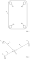
- FIG 1 illustrates an example of an apparatus 10 comprising multiple antennas 20.
- the multiple antennas 20 are spatially diverse- they have different physical positions relative to each other.
- Each antenna 20 is configured to receive a positioning reference signal 4illustrated in FIG 2 ).
- a first antenna 20 1 , a second antenna 20 2 , a third antenna 20 3 and a fourth antenna 20 4 are positioned at or towards corners or edges of the apparatus 10.
- the first antenna 20 1 , the second antenna 20 2 , the third antenna 20 3 and the fourth antenna 20 4 are spaced apart, to a significant or to a maximum or near maximum extent.
- FIG 2 illustrates a positioning system comprising multiple different reference points 2.
- the multiple reference points 2 are spatially diverse- they have different physical positions relative to each other.
- a first reference point 2 1 transmits a first reference signal 4 1
- a second reference point 2 2 transmits a second reference signal 4 2
- a third reference point 2 3 transmits a third reference signal 4 3 .
- Each reference point 2 is configured to transmit a positioning reference signal 4.
- the positioning reference signal 4 can comprise far field electromagnetic waves, and can therefore be referred to as a radio signal which includes radio frequency signals and microwave frequency signals, for example.
- the positioning reference signal 4 transmitted from a reference point 2 can have different radio characteristics than the positioning reference signal 4 transmitted from a different reference point 2.
- the positioning reference signal 4 transmitted from a reference point 2 can comprise data that is different to data comprised in a positioning reference signal 4 transmitted from a different reference point 2.
- the apparatus 10 receives the multiple positioning reference signals 4 from the different respective reference points 2.
- the reception of multiple positioning reference signal 4 provides information used to estimate a distance (or a proxy parameter dependent upon the distance) that changes with the spatial separation between the apparatus 10 and the reference point 2 that has transmitted the positioning reference signal 4 received at the apparatus.
- the reception of multiple positioning reference signals 4 provides the estimated distances (or proxy parameters dependent upon the distances) from the apparatus 10 to the respective reference points 2 transmitting the multiple positioning reference signals 4.
- An estimated distance can, for example, be expressed as an absolute distance- the spatial separation between the apparatus 10 and the reference point 2 that has transmitted the positioning reference signal 4 received at the apparatus 10 or can, for example, be expressed as a relative distance- a difference between two such physical distances.
- a time of arrival of positioning reference signal 4 is used as a proxy parameter for estimated distance and a difference between time of arrival of positioning reference signals 4 (delta time of arrival) is used as a proxy parameter for a difference between distances to the respective reference points 2.
- a time of arrival of a positioning reference signal 4, relative to its time of transmission, can be used as a proxy parameter for absolute distance.
- a difference between a time of arrival of a positioning reference signal 4 from one reference point 2 and a time of arrival of a positioning reference signal 4 from a different reference point 2 can be used as a proxy parameter for relative distance.
- Knowledge of the estimated distances (absolute or relative) of the apparatus 10 is used with knowledge of positions of the reference points 2 that transmitted received positioning reference signals 4 to position the apparatus 10. This positioning can, for example, occur at the apparatus 10 or remote from the apparatus 10. Knowledge of the estimated distances (absolute or relative) of the apparatus 10 can be transferred from the apparatus 10 for such remote determination.
- the apparatus 10 is configured as a terminal of a radio telecommunication network.
- the apparatus 10 can be user equipment in a third-generation partnership (3GPP) radio telecommunication network.
- 3GPP third-generation partnership
- a base station is used to communicate with a terminal over a radio interface.
- the reference points 2 are base stations of the radio telecommunication network.
- the positioning reference signals 4 are downlink reference signals controlled by the radio telecommunication network.
- the positioning reference signal 4 has a frequency of less than 6 or 8 GHz.
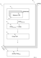
- FIG 3 illustrates a method 60.
- the method comprises a series of blocks 50 1 , 50 2 , 50 3 ... each associated with a respective positioning reference signal (PRS) 4 1 , 4 2 , 4 3 ... transmitted from respective reference points 2 1 , 2 2 , 2 3 ...
- Each block 50 i compensates a distance estimate d i (by compensating the equivalent time of arrival ToA i ) based on reception of the respective positioning reference signal (PRS) 4 i at one or more of the antennas 20 of the apparatus 10.
- time of arrival is compensated, however, in other examples the compensation can be applied to delta time of arrival or equivalent parameters.
- ToA time of arrival
- ⁇ ToA ⁇ antenna set of time of arrivals 65 associated with the set of multiple antennas 20 ( ⁇ antennas ⁇ ).
- the method comprises: obtaining a compensated time of arrival measurement 69 for a first positioning reference signal 4 1 from a first reference point 2 1 comprising:
- the method comprises: obtaining a compensated time of arrival measurement 69 for a second positioning reference signal 4 2 from a second reference point 2 2 comprising:
- the method comprises: obtaining a compensated time of arrival measurement 69 for an ith positioning reference signal 4 i from an ith reference point 2 i comprising:
- the method comprises providing compensated time of arrival measurements 69 for the first positioning reference signal 4 1 and the second positioning reference signal 4 2 (and optionally other compensated time of arrival measurements 69 for other positioning reference signals) to enable positioning of the apparatus 10.
- the apparatus 10 is configured to perform the method 60 and comprises means for converting measurements of time of arrival 65 of a positioning reference signal 4 i from reference point 4 i at the multiple antennas 20 to a compensation value 67 and using the compensation value 67 to produce a compensated time of arrival measurement 69 for the positioning reference signal 4 i and is configured to provide 70 compensated time of arrival measurements 69 for a plurality of positioning reference signals ...4 i-1 , 4 i , 4 i+1 ... from different reference points ...2 i-1 , 2 i , 2 i+1 ... to enable positioning of the apparatus 10.
- the apparatus 10 can comprise means for measuring 64 time of arrival 65of a positioning reference signal 4 i at the multiple antennas 20.
- the measurement can comprise measuring 64 the time of arrival 65 of that positioning reference signal 4 at each one of the multiple antennas 20 or a subset of the multiple antennas 20.
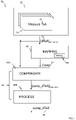
- FIG 4 illustrates an example of block 50 i as previously described that is used for obtaining a compensated time of arrival measurement 69 for a positioning reference signal 4 i from a reference point 2 i .
- Some or all of the blocks 50 i in FIG 3 can be replaced by an equivalent block 50i from FIG 4 .
- delta time of arrival (dToA) is compensated.
- dToA delta time of arrival
- PRS positioning reference signal
- dToA delta time of arrival
- ⁇ dToA ⁇ antennas set of time of arrivals 65 associated with the set of multiple antennas 20
- the apparatus 10 comprises a mapping database 100 that is used for converting 66 the measurements of time of arrival 65 of the positioning reference signal 4 i at multiple antennas 20 of the apparatus 10 to a compensation value 67.
- the mapping database 100 can comprise multiple entries each entry being associated with a compensation value 67 (which can comprise a set of compensations for one or more of the respective measurements of time of arrival 65).
- the different entries are each accessed via different combinations of measurements of time of arrival 65 of a positioning reference signal 4 at the multiple antennas 20.
- the set of measurements of time of arrival of the positioning reference signal 4 i at the multiple antennas 20 can be used to look-up a compensation value 67 i .
- An entry of the database 100 can store a set of compensations (as a compensation value 67 i ) for the measurements of time of arrival 65 of a positioning reference signal 4 i at the multiple antennas 20 or store values for calculating a set of compensations (as a compensation value 67 i ) for the measurements of time of arrival 65 of a positioning reference signal 4 at the multiple antennas 20.
- the apparatus 10 comprises means for accessing an entry of the database 100 via an ordered sequence of measurements of time of arrival 65 of a positioning reference signal 4 i at the multiple antennas 20 to obtain a compensation value 67 i for the measurements of time of arrival 65 of the positioning reference signal 4 at the multiple antennas 20.
- Each compensation in the set of compensations defined by the compensation value 67 i can be used to compensate 68A each time of arrival 65 of a positioning reference signal 4 at each of the respective antennas 20.
- the compensated times of arrival of the positioning reference signal 4 at the respective antennas 20 can then be processed 68B to obtain a compensated time of arrival 69 of the positioning reference signal 4 at the apparatus 10.
- the compensation can be applied to the time of arrival by applying it to an absolute value (e.g. ToA FIG 3 ) or a relative value (e.g. dToA FIG 4 ).
- an absolute value e.g. ToA FIG 3
- a relative value e.g. dToA FIG 4
- the radiation patterns 22 associated with the antennas 20 are not identical.
- An antenna 20 j (not illustrated) has an associated radiation pattern 22 j (illustrated).
- the different radiation patterns 22 can, for example, arise from intentional differences in design or unintentional differences arising from manufacturing tolerances.
- the physical placement on the chassis can be a significant factor.
- the different radiation patterns 22 can, for example, be at least partially caused by different local environments of the antennas 20. For example, the presence of electrical conductors or electrical paths to ground can affect capacitance and hence the antenna radiation pattern 22 of the antenna 20.
- phase center PC phase space
- O physical center
- phase center offset (PCO) for an antenna 20 is an offset of a physical phase reference position (phase center) from a defined origin (e.g. physical center).
- the defined origin O is used to measure an angle of arrival (AoA) ⁇ of a positioning reference signal 4.
- a radiation pattern 22 causes a particular phase center offset (PCO) for that angle of arrival (AoA).
- the PCO is the offset of the physical phase reference position from the origin.
- the displacement of the phase center offset (PCO) from the origin O can be represented as a propagation offset vector (POV).
- the length of the propagation offset vector (POV) represents a delay (relative to the origin) that comprises a fixed component and a variable component.
- the fixed component if any, represents the spatial separation between the origin O and the phase reference position (e.g. the physical center) of the antenna.
- the variable component represents the difference between the phase reference position (e.g. physical center) of the antenna and the phase center of the antenna 20.
- the variable component is compensated for by the compensation value 67.
- the compensation value 67 (compensations for each antenna 20) for different angles of arrival (AoA) ⁇ can be measured in the laboratory to create entries for the mapping database 100 which can then be loaded onto all the apparatus 10 in a production line.
- the lengths of the propagation offset vectors (POV) of the antennas 20 are independent of power variations due to fading and can be used to estimate the Angle of Arrival (AoA).
- a compensation (C j ⁇ ) compensates for a phase center offset of a particular antenna 20 j that receives the positioning reference signal 4 from a particular direction of arrival ⁇ .
- the phase center offset can vary with the antenna 20 j and varies with the angle of arrival ⁇ of the positioning reference signal 4.
- the pattern of lengths of the propagation offset vectors (POV) of the antennas 20 can be used to estimate the Angle of Arrival (AoA). Also, the pattern of differences between lengths of the propagation offset vectors (POV) in the antennas 20 can be used to estimate the Angle of Arrival (AoA). 20 j . Thus, the pattern of time differences ⁇ dToA ⁇ antennas between time of arrival for an incoming positioning reference signal 4 can be used to estimate the Angle of Arrival (AoA) of the positioning reference signal 4.
- the pattern of time differences ⁇ dToA ⁇ antennas or the associated estimated Angle of Arrival (AoA) can be used to look-up, in the mapping database 100, the compensation (C j ⁇ ) for each antenna 20 j at that angle of arrival ⁇ .
- the result is a set of compensations, one for each antenna 20, for a particular positioning reference signal associated with the angle of arrival ⁇ .
- the set of compensations (C j ⁇ ) for all antennas at a particular angle of arrival can be accessed 66 as a database entry as the compensation value 67.
- the compensation value 67 (set of compensations for the antennas) is used to compensate 68A the time differences ⁇ dToA ⁇ antennas of the respective antennas to produce a set of compensated time differences ⁇ comp_dTOA ⁇ antennas for the respective antennas.
- the set of compensated time differences ⁇ comp_dTOA ⁇ antennas for the respective antennas 20 are processed 68B to produce a compensated time difference 69 (comp_dTOA) for the apparatus 10.
- the measurements of time of arrival 65 of a particular positioning reference signal 4 i at multiple antennas 20 j of an apparatus 10 are converted to a compensation value 67 used to produce a compensated time of arrival measurement 69 for the particular positioning reference signal 4 i .
- the time of arrival 65 is a time difference dToA and the compensated time of arrival measurement 69 is a compensated time difference (comp_dTOA).
- the processing 68B can, for example, comprise calculating an average of the compensated time differences ⁇ comp_dTOA ⁇ antennas in the set of compensated time differences ⁇ comp_dTOA ⁇ antennas . This can be an average across all antennas for a particular positioning reference signal (particular angle of arrival). The average is the compensated time difference 69 (comp_dTOA) for the apparatus 10.
- the processing 68B can, for example, comprise selecting one of the compensated time differences comp_dTOA in the set of compensated time differences ⁇ comp_dTOA ⁇ antennas .
- the selected one of compensated time differences is the compensated time difference 69 (comp_dTOA) for the apparatus 10.
- the selection can be based on any suitable criterion. For example, the compensated time difference with smallest variance can be selected.
- This process 50 can be repeated for multiple different positioning reference signals 4 with different angles of arrival, as previously described, to produce a compensated time difference 69 (comp_dTOA) for the apparatus 10 for each positioning reference signal 4.
- the apparatus 10 enables positioning of the apparatus 10 using downlink time difference of arrival (DL-TDOA) based on the compensated time differences 69 (comp_dTOA) for the apparatus 10 for the multiple positioning reference signals 4.
- DL-TDOA downlink time difference of arrival
- comp_dTOA compensated time differences 69
- the apparatus 10 can be configured to convert measurements of time of arrival of a positioning reference signal 4 at the multiple antennas 20 to current phase center offset values for the multiple antennas 20 and using the current phase center offset values for the multiple antennas 20 to compensate a time of arrival measurement for the positioning reference signal 4.
- An entry of the database 100, associated with a particular angle of arrival, is associated with a phase center offset for each of the multiple antennas 20.
- the associated phase center offset determines the compensations C j ⁇ used for compensating time of arrival of a positioning reference signal 4 (received at angle of arrival ⁇ ) at the respective antennas 20 j .
- simple trilateration to find a three-dimensional position, normally requires that the reference points 2 are separated over three dimensions. If the reference points 2 are separated over two-dimensions (a single plane), then simple trilateration provides ambiguous positions on either side of the plane (e.g. in some examples. the locus of intersecting spheres). The ambiguity can be resolved by not only matching the equivalent distance to the reference points on the plane (radius of the spheres) but also matching a detected angle of arrival to the expected angle of arrival for the respective reference points 2.
- the reference points 2 are separated over two dimensions. If the reference points 2 are separated over a single dimension (a single line), then simple trilateration provides ambiguous positions on either side of the line (e.g. in some examples the locus of intersecting circles). The ambiguity can be resolved by not only matching the distances to the reference points 2 on the line (radius of the circles) but also matching a detected angle of arrival to the expected angle of arrival for the respective reference points 2. As illustrated in FIG 7 & 8 , the vector difference between the detected angle of arrivals of the positioning reference signals resolves the ambiguity. If the vector difference A is less than 180° it is to one side of the line (the right-side in FIG 8 ) and if the vector difference is more than 180° it is to the other side of the line.
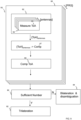
- FIG 9 illustrates an example, in which the example of FIG 3 has been extended.
- trilateration is enabled. If there are an insufficient number of appropriately positioned reference points 2 to enable trilateration without ambiguity, then trilateration is not enabled and instead disambiguation is enabled.
- the disambiguation uses a detected angle of arrival of the positioning reference signal 4.
- the position of the apparatus 10 is determined by disambiguating the ambiguous positions using angle of arrival information.
- the pattern of time differences ⁇ dTOA ⁇ antennas between time of arrival for an incoming positioning reference signal 4 can be used to estimate the Angle of Arrival (AoA) of the reference positioning reference signal 4.
- the Angle of Arrival (AoA) of a first positioning reference signal 4 1 and the Angle of Arrival (AoA) of the second positioning reference signal 4 2 can be processed 85 to produce a parameter that is used to enable disambiguation 87 of the ambiguous positions.
- the Angle of Arrival (AoA) of the first positioning reference signal 4 1 can be subtracted from the Angle of Arrival (AoA) of the second positioning reference signal 4 2 to produce a difference angle that can be used to enable disambiguation 87 of the ambiguous position.
- the apparatus 10 can obtain the angle of arrival when the mapping database 100 is accessed as previously described.
- the pattern of time differences ⁇ dTOA ⁇ antenna between time of arrival for an incoming positioning reference signal 4 at the different antennas 20 can be used to estimate the Angle of Arrival (AoA) of the positioning reference signal.
- AoA Angle of Arrival
- the apparatus 10 can be configured, if the measurements of time of arrival of the positioning reference signal 4 at the multiple antennas 20, for each of a plurality of positioning reference signals 4 from different reference points 2, are insufficient to disambiguate a position of the apparatus 10 to:
- the apparatus 10 can be configured to use the compensated time of arrival measurements to position the apparatus 10.
- the apparatus 10 performs positioning of the apparatus 10 and the apparatus 10 receives positioning assistance data from the network.
- the positioning assistance data can, for example, include global position coordinates for the reference points 2.
- the apparatus 10 can be configured to transmit the compensated time of arrival measurements for a plurality of positioning reference signals 4 from different reference points 2 to enable positioning of the apparatus 10.
- the apparatus 10 assists positioning of the apparatus 10 by another device, and the apparatus 10 does not need to receive positioning assistance data from the network.
- the apparatus 10 can, for example, provide the compensated TOAs (for all positioning reference signals) or the origin-referenced dTOA between all positioning reference signals to the network which determines the position.
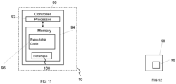
- Fig 11 illustrates an example of a controller 90 of the apparatus 10.
- the controller 90 can provide means for performing the above-described methods.
- controller 90 may be as controller circuitry.
- the controller 90 may be implemented in hardware alone, have certain aspects in software including firmware alone or can be a combination of hardware and software (including firmware).
- the controller 90 may be implemented using instructions that enable hardware functionality, for example, by using executable instructions of a computer program 96 in a general-purpose or special-purpose processor 92 that may be stored on a computer readable storage medium (disk, memory etc) to be executed by such a processor 92.
- a general-purpose or special-purpose processor 92 may be stored on a computer readable storage medium (disk, memory etc) to be executed by such a processor 92.
- the processor 92 is configured to read from and write to the memory 94.
- the processor 92 may also comprise an output interface via which data and/or commands are output by the processor 92 and an input interface via which data and/or commands are input to the processor 92.
- the memory 94 can in some examples store, permanently or temporarily, all or part of the mapping database 100.
- the memory 94 stores a computer program 96 comprising computer program instructions (computer program code) that controls the operation of the apparatus 10 10 when loaded into the processor 92.
- the computer program instructions, of the computer program 96 provide the logic and routines that enables the apparatus 10 to perform the methods illustrated in the Figures.
- the processor 92 by reading the memory 94 is able to load and execute the computer program 96.
- the apparatus 10 therefore comprises:
- the computer program 96 may arrive at the apparatus 10 via any suitable delivery mechanism 98.
- the delivery mechanism 98 may be, for example, a machine readable medium, a computer-readable medium, a nontransitory computer-readable storage medium, a computer program product, a memory device, a record medium such as a Compact Disc Read-Only Memory (CD-ROM) or a Digital Versatile Disc (DVD) or a solid state memory, an article of manufacture that comprises or tangibly embodies the computer program 96.
- the delivery mechanism may be a signal configured to reliably transfer the computer program 96.
- the apparatus 10 may propagate or transmit the computer program 96 as a computer data signal.
- the computer program 96 comprises instructions that when run on at least one processor 92 of an apparatus 10 causes the apparatus 10 to:
- the computer program instructions may be comprised in a computer program, a nontransitory computer readable medium, a computer program product, a machine readable medium. In some but not necessarily all examples, the computer program instructions may be distributed over more than one computer program.
- memory 94 is illustrated as a single component/circuitry it may be implemented as one or more separate components/circuitry some or all of which may be integrated/removable and/or may provide permanent/semi-permanent/ dynamic/cached storage.
- processor 92 is illustrated as a single component/circuitry it may be implemented as one or more separate components/circuitry some or all of which may be integrated/removable.
- the processor 92 may be a single core or multi-core processor.
- references to 'computer-readable storage medium', 'computer program product', 'tangibly embodied computer program' etc. or a 'controller', 'computer', 'processor' etc. should be understood to encompass not only computers having different architectures such as single /multi- processor architectures and sequential (Von Neumann)/parallel architectures but also specialized circuits such as fieldprogrammable gate arrays (FPGA), application specific circuits (ASIC), signal processing devices and other processing circuitry.
- References to computer program, instructions, code etc. should be understood to encompass software for a programmable processor or firmware such as, for example, the programmable content of a hardware device whether instructions for a processor, or configuration settings for a fixed-function device, gate array or programmable logic device etc.
- circuitry may refer to one or more or all of the following:
- circuitry also covers an implementation of merely a hardware circuit or processor and its (or their) accompanying software and/or firmware.
- circuitry also covers, for example and if applicable to the particular claim element, a baseband integrated circuit for a mobile device or a similar integrated circuit in a server, a cellular network device, or other computing or network device.
- the blocks illustrated in the Figures may represent steps in a method and/or sections of code in the computer program 96.
- the illustration of a particular order to the blocks does not necessarily imply that there is a required or preferred order for the blocks and the order and arrangement of the block may be varied. Furthermore, it may be possible for some blocks to be omitted.
- the apparatus 10 comprises multiple antennas 20; and positioning means 90 for enabling positioning of the apparatus 10.
- the positioning means 90 comprises:
- the above-described examples can provide for positioning of the apparatus 10 within a sub-meter accuracy.
- the above-described examples can provide for positioning of the apparatus 10 within an accuracy of 20cm or even below 10cm.
- the above-described examples can provide for positioning of the apparatus 10 with low latency, high network efficiency and/or high device efficiency.
- the above-described examples find application as enabling components of: automotive systems; telecommunication systems; electronic systems including consumer electronic products; distributed computing systems; media systems for generating or rendering media content including audio, visual and audio visual content and mixed, mediated, virtual and/or augmented reality; personal systems including personal health systems or personal fitness systems; navigation systems; user interfaces also known as human machine interfaces; networks including cellular, non-cellular, and optical networks; ad-hoc networks; the internet; the internet of things; virtualized networks; and related software and services.
- a property of the instance can be a property of only that instance or a property of the class or a property of a sub-class of the class that includes some but not all of the instances in the class. It is therefore implicitly disclosed that a feature described with reference to one example but not with reference to another example, can where possible be used in that other example as part of a working combination but does not necessarily have to be used in that other example.
- 'a' or 'the' is used in this document with an inclusive not an exclusive meaning. That is any reference to X comprising a/the Y indicates that X may comprise only one Y or may comprise more than one Y unless the context clearly indicates the contrary. If it is intended to use 'a' or 'the' with an exclusive meaning then it will be made clear in the context. In some circumstances the use of 'at least one' or 'one or more' may be used to emphasis an inclusive meaning but the absence of these terms should not be taken to infer any exclusive meaning.
- the presence of a feature (or combination of features) in a claim is a reference to that feature or (combination of features) itself and also to features that achieve substantially the same technical effect (equivalent features).
- the equivalent features include, for example, features that are variants and achieve substantially the same result in substantially the same way.
- the equivalent features include, for example, features that perform substantially the same function, in substantially the same way to achieve substantially the same result.
Landscapes
- Engineering & Computer Science (AREA)
- Physics & Mathematics (AREA)
- General Physics & Mathematics (AREA)
- Radar, Positioning & Navigation (AREA)
- Remote Sensing (AREA)
- Computer Networks & Wireless Communication (AREA)
- Signal Processing (AREA)
- Position Fixing By Use Of Radio Waves (AREA)
Priority Applications (3)
| Application Number | Priority Date | Filing Date | Title |
|---|---|---|---|
| EP21199607.9A EP4155751A1 (de) | 2021-09-28 | 2021-09-28 | Positionierung einer vorrichtung mittels funksignalen |
| US17/935,792 US12392861B2 (en) | 2021-09-28 | 2022-09-27 | Positioning of an apparatus using radio signals |
| CN202211188034.9A CN115877316A (zh) | 2021-09-28 | 2022-09-28 | 使用无线电信号的装置的定位 |
Applications Claiming Priority (1)
| Application Number | Priority Date | Filing Date | Title |
|---|---|---|---|
| EP21199607.9A EP4155751A1 (de) | 2021-09-28 | 2021-09-28 | Positionierung einer vorrichtung mittels funksignalen |
Publications (1)
| Publication Number | Publication Date |
|---|---|
| EP4155751A1 true EP4155751A1 (de) | 2023-03-29 |
Family
ID=78134780
Family Applications (1)
| Application Number | Title | Priority Date | Filing Date |
|---|---|---|---|
| EP21199607.9A Pending EP4155751A1 (de) | 2021-09-28 | 2021-09-28 | Positionierung einer vorrichtung mittels funksignalen |
Country Status (3)
| Country | Link |
|---|---|
| US (1) | US12392861B2 (de) |
| EP (1) | EP4155751A1 (de) |
| CN (1) | CN115877316A (de) |
Families Citing this family (2)
| Publication number | Priority date | Publication date | Assignee | Title |
|---|---|---|---|---|
| KR20230078643A (ko) * | 2020-09-22 | 2023-06-02 | 퀄컴 인코포레이티드 | 기준 신호 구성 포지셔닝 및 관리 |
| US20240097774A1 (en) * | 2022-08-16 | 2024-03-21 | Nvidia Corporation | Wireless beam selection |
Citations (4)
| Publication number | Priority date | Publication date | Assignee | Title |
|---|---|---|---|---|
| EP3254482A1 (de) * | 2015-02-06 | 2017-12-13 | Qualcomm Incorporated | Vorspannungskompensation zwischen frequenzen für zeitdifferenzmessungen bei positionsbestimmungen |
| EP3360201A1 (de) * | 2015-10-08 | 2018-08-15 | Polte Corporation | Einfallswinkelpositionierungssystem zur verfolgung von objekten |
| US20190037351A1 (en) * | 2005-12-15 | 2019-01-31 | Polte Corporation | Angle of arrival (aoa) positioning method and system for positional finding and tracking objects using reduced attenuation rf technology |
| US20190335416A1 (en) * | 2018-04-30 | 2019-10-31 | Qualcomm Incorporated | Reference signal measurement in mobile device having multiple antenna receiver |
Family Cites Families (15)
| Publication number | Priority date | Publication date | Assignee | Title |
|---|---|---|---|---|
| GB0325622D0 (en) | 2003-11-03 | 2003-12-10 | Cambridge Consultants | System for determining positional information |
| US10834531B2 (en) | 2005-12-15 | 2020-11-10 | Polte Corporation | Multi-path mitigation in rangefinding and tracking objects using reduced attenuation RF technology |
| US20080129613A1 (en) | 2006-12-05 | 2008-06-05 | Nokia Corporation | Calibration for re-configurable active antennas |
| US7855681B2 (en) | 2008-11-19 | 2010-12-21 | Harris Corporation | Systems and methods for determining element phase center locations for an array of antenna elements |
| CN102323489B (zh) | 2011-08-18 | 2013-09-11 | 北京华力创通科技股份有限公司 | 对接收机天线的相位中心进行校准的方法和装置 |
| US10863313B2 (en) | 2014-08-01 | 2020-12-08 | Polte Corporation | Network architecture and methods for location services |
| EP2883076A1 (de) | 2012-08-13 | 2015-06-17 | Telefonaktiebolaget LM Ericsson (PUBL) | Verbesserung einer positionierung mit übertragungszeit-einstellungsinformationen |
| CN102830406B (zh) | 2012-08-30 | 2014-05-28 | 航天东方红卫星有限公司 | 一种gps天线相位中心变化对绝对定位精度的修正方法 |
| CN104502926B (zh) | 2014-12-17 | 2017-10-24 | 武汉大学 | 一种基于精密机械臂的室外gnss接收机绝对天线相位中心校正方法 |
| CN113167855B (zh) * | 2018-12-19 | 2024-06-18 | 瑞典爱立信有限公司 | 差分匹配求和定位 |
| CN111435910B (zh) | 2019-01-11 | 2023-05-23 | 株式会社Kt | 在新无线电中执行定位的装置和方法 |
| US12057918B2 (en) | 2019-08-16 | 2024-08-06 | Nokia Technologies Oy | Non-line-of-sight path detection for user equipment positioning in wireless networks |
| WO2021032300A1 (en) | 2019-08-21 | 2021-02-25 | Nokia Solutions And Networks Oy | Apparatus, method and computer program for determining beamforming direction |
| US12553979B2 (en) | 2020-09-30 | 2026-02-17 | Nokia Technologies Oy | Compensating for dynamic antenna array phase deviation |
| EP4726434A2 (de) | 2020-09-30 | 2026-04-15 | Nokia Technologies Oy | Dynamische kompensation der winkelphasenabweichung einer gruppenantenne zur breitstrahlpositionierung |
-
2021
- 2021-09-28 EP EP21199607.9A patent/EP4155751A1/de active Pending
-
2022
- 2022-09-27 US US17/935,792 patent/US12392861B2/en active Active
- 2022-09-28 CN CN202211188034.9A patent/CN115877316A/zh active Pending
Patent Citations (6)
| Publication number | Priority date | Publication date | Assignee | Title |
|---|---|---|---|---|
| US20190037351A1 (en) * | 2005-12-15 | 2019-01-31 | Polte Corporation | Angle of arrival (aoa) positioning method and system for positional finding and tracking objects using reduced attenuation rf technology |
| EP3254482A1 (de) * | 2015-02-06 | 2017-12-13 | Qualcomm Incorporated | Vorspannungskompensation zwischen frequenzen für zeitdifferenzmessungen bei positionsbestimmungen |
| EP3254482B1 (de) * | 2015-02-06 | 2019-09-04 | Qualcomm Incorporated | Vorspannungskompensation zwischen frequenzen für zeitdifferenzmessungen bei positionsbestimmungen |
| EP3360201A1 (de) * | 2015-10-08 | 2018-08-15 | Polte Corporation | Einfallswinkelpositionierungssystem zur verfolgung von objekten |
| EP3360201B1 (de) * | 2015-10-08 | 2021-07-07 | PoLTE Corporation | Einfallswinkelpositionierungssystem zur verfolgung von objekten |
| US20190335416A1 (en) * | 2018-04-30 | 2019-10-31 | Qualcomm Incorporated | Reference signal measurement in mobile device having multiple antenna receiver |
Also Published As
| Publication number | Publication date |
|---|---|
| US20230095643A1 (en) | 2023-03-30 |
| CN115877316A (zh) | 2023-03-31 |
| US12392861B2 (en) | 2025-08-19 |
Similar Documents
| Publication | Publication Date | Title |
|---|---|---|
| Wen et al. | A survey on 5G massive MIMO localization | |
| KR101544315B1 (ko) | 무선 네트워크에서의 삼변측량법을 이용한 효과적인 3차원 위치 추정 방법 및 이를 실시하기 위한 프로그램이 기록된 기록 매체 | |
| US12392861B2 (en) | Positioning of an apparatus using radio signals | |
| Noroozi et al. | Algebraic solution for three‐dimensional TDOA/AOA localisation in multiple‐input–multiple‐output passive radar | |
| EP2984882A1 (de) | Positionsbestimmung einer mobilen vorrichtung | |
| Norouzi et al. | Joint time difference of arrival/angle of arrival position finding in passive radar | |
| Doukhnitch et al. | An efficient approach for trilateration in 3D positioning | |
| CN112118624B (zh) | 改进距离测量精度的方法及用于其的电子装置 | |
| Zhu et al. | Indoor localization for passive moving objects based on a redundant SIMO radar sensor | |
| US12146975B2 (en) | Positioning system and method | |
| CN106604391A (zh) | 一种室内wifi定位方法及服务器 | |
| KR101627419B1 (ko) | 이동 노드의 위치 추정 방법 및 그 장치 | |
| Huang et al. | 3D TDOA/AOA localization in MIMO passive radar with transmitter and receiver position errors | |
| Wang et al. | An improved 3D indoor positioning study with ray tracing modeling for 6G systems | |
| WO2016067064A1 (en) | A method and system for 3d position estimation of an object using time of arrival measurements | |
| CN106063317B (zh) | 业务热点的定位方法及装置 | |
| Wang et al. | Target localisation in multistatic radar using BR, TDOA, and AOA measurements | |
| Zhang et al. | High precision positioning algorithm based on carrier phase and time of arrival | |
| Lee et al. | Optimised solution for hybrid TDOA/AOA‐based geolocation using Nelder‐Mead simplex method | |
| KR101689628B1 (ko) | 고정 신호원의 위치 추정 장치 및 방법 | |
| Zhang et al. | An efficient estimator for target localization in a multistation redundancy system without matrix inversion | |
| EP4086652B1 (de) | Mobile positioniervorrichtung sowie verfahren und programm zur ortsmessung in einem drahtlosen netzwerk, die auf einer mobilen plattform implementiert sind | |
| He | DOA estimation approach based on parallel stochastic resonance system and signal correlation calculation | |
| WO2024001409A1 (zh) | 通信方法以及通信装置 | |
| Erić et al. | An approach for determination of antenna positions in distributed antenna system used for UWB indoor self-localization: Experimental results |
Legal Events
| Date | Code | Title | Description |
|---|---|---|---|
| PUAI | Public reference made under article 153(3) epc to a published international application that has entered the european phase |
Free format text: ORIGINAL CODE: 0009012 |
|
| STAA | Information on the status of an ep patent application or granted ep patent |
Free format text: STATUS: THE APPLICATION HAS BEEN PUBLISHED |
|
| AK | Designated contracting states |
Kind code of ref document: A1 Designated state(s): AL AT BE BG CH CY CZ DE DK EE ES FI FR GB GR HR HU IE IS IT LI LT LU LV MC MK MT NL NO PL PT RO RS SE SI SK SM TR |
|
| STAA | Information on the status of an ep patent application or granted ep patent |
Free format text: STATUS: REQUEST FOR EXAMINATION WAS MADE |
|
| 17P | Request for examination filed |
Effective date: 20230925 |
|
| RBV | Designated contracting states (corrected) |
Designated state(s): AL AT BE BG CH CY CZ DE DK EE ES FI FR GB GR HR HU IE IS IT LI LT LU LV MC MK MT NL NO PL PT RO RS SE SI SK SM TR |
|
| STAA | Information on the status of an ep patent application or granted ep patent |
Free format text: STATUS: EXAMINATION IS IN PROGRESS |