EP4155773A1 - Vorrichtung und verfahren zur rauschunterdrückung für ein wetterradar - Google Patents
Vorrichtung und verfahren zur rauschunterdrückung für ein wetterradar Download PDFInfo
- Publication number
- EP4155773A1 EP4155773A1 EP22196602.1A EP22196602A EP4155773A1 EP 4155773 A1 EP4155773 A1 EP 4155773A1 EP 22196602 A EP22196602 A EP 22196602A EP 4155773 A1 EP4155773 A1 EP 4155773A1
- Authority
- EP
- European Patent Office
- Prior art keywords
- radio interference
- echo
- observation
- azimuth angles
- observation information
- Prior art date
- Legal status (The legal status is an assumption and is not a legal conclusion. Google has not performed a legal analysis and makes no representation as to the accuracy of the status listed.)
- Withdrawn
Links
Images




Classifications
-
- G—PHYSICS
- G01—MEASURING; TESTING
- G01S—RADIO DIRECTION-FINDING; RADIO NAVIGATION; DETERMINING DISTANCE OR VELOCITY BY USE OF RADIO WAVES; LOCATING OR PRESENCE-DETECTING BY USE OF THE REFLECTION OR RERADIATION OF RADIO WAVES; ANALOGOUS ARRANGEMENTS USING OTHER WAVES
- G01S13/00—Systems using the reflection or reradiation of radio waves, e.g. radar systems; Analogous systems using reflection or reradiation of waves whose nature or wavelength is irrelevant or unspecified
- G01S13/88—Radar or analogous systems specially adapted for specific applications
- G01S13/95—Radar or analogous systems specially adapted for specific applications for meteorological use
-
- G—PHYSICS
- G01—MEASURING; TESTING
- G01S—RADIO DIRECTION-FINDING; RADIO NAVIGATION; DETERMINING DISTANCE OR VELOCITY BY USE OF RADIO WAVES; LOCATING OR PRESENCE-DETECTING BY USE OF THE REFLECTION OR RERADIATION OF RADIO WAVES; ANALOGOUS ARRANGEMENTS USING OTHER WAVES
- G01S7/00—Details of systems according to groups G01S13/00, G01S15/00, G01S17/00
- G01S7/02—Details of systems according to groups G01S13/00, G01S15/00, G01S17/00 of systems according to group G01S13/00
- G01S7/023—Interference mitigation, e.g. reducing or avoiding non-intentional interference with other HF-transmitters, base station transmitters for mobile communication or other radar systems, e.g. using electro-magnetic interference [EMI] reduction techniques
-
- G—PHYSICS
- G01—MEASURING; TESTING
- G01S—RADIO DIRECTION-FINDING; RADIO NAVIGATION; DETERMINING DISTANCE OR VELOCITY BY USE OF RADIO WAVES; LOCATING OR PRESENCE-DETECTING BY USE OF THE REFLECTION OR RERADIATION OF RADIO WAVES; ANALOGOUS ARRANGEMENTS USING OTHER WAVES
- G01S7/00—Details of systems according to groups G01S13/00, G01S15/00, G01S17/00
- G01S7/02—Details of systems according to groups G01S13/00, G01S15/00, G01S17/00 of systems according to group G01S13/00
- G01S7/40—Means for monitoring or calibrating
- G01S7/4004—Means for monitoring or calibrating of parts of a radar system
- G01S7/4008—Means for monitoring or calibrating of parts of a radar system of transmitters
-
- G—PHYSICS
- G01—MEASURING; TESTING
- G01S—RADIO DIRECTION-FINDING; RADIO NAVIGATION; DETERMINING DISTANCE OR VELOCITY BY USE OF RADIO WAVES; LOCATING OR PRESENCE-DETECTING BY USE OF THE REFLECTION OR RERADIATION OF RADIO WAVES; ANALOGOUS ARRANGEMENTS USING OTHER WAVES
- G01S13/00—Systems using the reflection or reradiation of radio waves, e.g. radar systems; Analogous systems using reflection or reradiation of waves whose nature or wavelength is irrelevant or unspecified
- G01S13/02—Systems using reflection of radio waves, e.g. primary radar systems; Analogous systems
- G01S13/06—Systems determining position data of a target
- G01S13/08—Systems for measuring distance only
- G01S13/10—Systems for measuring distance only using transmission of interrupted, pulse modulated waves
-
- G—PHYSICS
- G01—MEASURING; TESTING
- G01S—RADIO DIRECTION-FINDING; RADIO NAVIGATION; DETERMINING DISTANCE OR VELOCITY BY USE OF RADIO WAVES; LOCATING OR PRESENCE-DETECTING BY USE OF THE REFLECTION OR RERADIATION OF RADIO WAVES; ANALOGOUS ARRANGEMENTS USING OTHER WAVES
- G01S13/00—Systems using the reflection or reradiation of radio waves, e.g. radar systems; Analogous systems using reflection or reradiation of waves whose nature or wavelength is irrelevant or unspecified
- G01S13/02—Systems using reflection of radio waves, e.g. primary radar systems; Analogous systems
- G01S13/06—Systems determining position data of a target
- G01S13/42—Simultaneous measurement of distance and other co-ordinates
-
- G—PHYSICS
- G01—MEASURING; TESTING
- G01S—RADIO DIRECTION-FINDING; RADIO NAVIGATION; DETERMINING DISTANCE OR VELOCITY BY USE OF RADIO WAVES; LOCATING OR PRESENCE-DETECTING BY USE OF THE REFLECTION OR RERADIATION OF RADIO WAVES; ANALOGOUS ARRANGEMENTS USING OTHER WAVES
- G01S13/00—Systems using the reflection or reradiation of radio waves, e.g. radar systems; Analogous systems using reflection or reradiation of waves whose nature or wavelength is irrelevant or unspecified
- G01S13/02—Systems using reflection of radio waves, e.g. primary radar systems; Analogous systems
- G01S13/50—Systems of measurement based on relative movement of target
- G01S13/58—Velocity or trajectory determination systems; Sense-of-movement determination systems
- G01S13/581—Velocity or trajectory determination systems; Sense-of-movement determination systems using transmission of interrupted pulse modulated waves and based upon the Doppler effect resulting from movement of targets
- G01S13/582—Velocity or trajectory determination systems; Sense-of-movement determination systems using transmission of interrupted pulse modulated waves and based upon the Doppler effect resulting from movement of targets adapted for simultaneous range and velocity measurements
-
- Y—GENERAL TAGGING OF NEW TECHNOLOGICAL DEVELOPMENTS; GENERAL TAGGING OF CROSS-SECTIONAL TECHNOLOGIES SPANNING OVER SEVERAL SECTIONS OF THE IPC; TECHNICAL SUBJECTS COVERED BY FORMER USPC CROSS-REFERENCE ART COLLECTIONS [XRACs] AND DIGESTS
- Y02—TECHNOLOGIES OR APPLICATIONS FOR MITIGATION OR ADAPTATION AGAINST CLIMATE CHANGE
- Y02A—TECHNOLOGIES FOR ADAPTATION TO CLIMATE CHANGE
- Y02A90/00—Technologies having an indirect contribution to adaptation to climate change
- Y02A90/10—Information and communication technologies [ICT] supporting adaptation to climate change, e.g. for weather forecasting or climate simulation
Definitions
- the present disclosure relates to an apparatus and method for removing noise for a weather radar and, more particularly, to an apparatus and method for removing noise for a weather radar, the apparatus and method being able to detecting a radio interference echo, which is noise due to radio interference that is generated by reception of other external radio waves to a weather radar except for a radio wave transmitted from the weather radar, separately from weather eco according to normal weather measurement, and being able to remove the radio interference echo.
- a radio interference echo which is noise due to radio interference that is generated by reception of other external radio waves to a weather radar except for a radio wave transmitted from the weather radar, separately from weather eco according to normal weather measurement, and being able to remove the radio interference echo.
- a weather radar (hereafter, radar) is equipment that transmits a radio wave (electromagnetic wave or pulse or radar beam) and measures average reflection intensity and location of a target in a sampling volume through the reception power and the reception time of a signal returning after being reflected by rain or snow (hydrometeor) that is the target.
- a radio wave electromagnetic wave or pulse or radar beam
- the weather radar can observe a 3D (volume) state of the atmosphere in the form of polar coordination by observing while changing an azimuth angle of 0 ⁇ 360 degrees and an altitude angle of 0 ⁇ 90 degrees of an antenna.
- An external radio wave transmitted by other radar equipment such as an airplane that transmits a radio wave around the weather radar may be received to the weather radar when the weather radar receives a radio wave reflected by a target after transmitting the radio wave, and accordingly, radio interference may be generated with the radio wave transmitted from the weather radar due to the external radio wave.
- observation information that is provided by the weather radar includes an abnormal echo due to radio interference other than a normal observation echo created on the basis of a radio wave reflected by a target related to weather such as precipitation.
- a radio interference echo due to radio interference is usually observed at certain some azimuth angles in a low-layer (low-altitude angle) observation in which an external source may exist.
- a radial velocity (V r ) has a characteristic that an observation value is not related to a radio interference echo, but a portion of a radial velocity is lost even in a precipitation echo, so a radial velocity is not used as a discrimination condition in data quality management in a normal observation state to prevent mis-removable of precipitation.
- radio interference echoes with various reflectivities may be detected in random directions up to a high altitude angle.
- abnormal radio interference echoes are different in characteristic from other non-weather echoes such as waves, chaff, and an abnormal radio wave, there is a need for specified characteristic variable and discrimination condition in order to completely discriminate and remove abnormal radio interference echoes from a precipitation echo.
- Patent Document Korean Patent No. 10-1846294
- An objective of the present disclosure is to discriminate and accurately detect an abnormal radio interference echo, which is generated in observation information created on the basis of an echo signal of a weather radar due to radio interference between an external radio wave and a reflective wave received when an external radio wave that is not a radio wave transmitted from a weather radar is received to the weather radar and the radio wave transmitted from the weather radar is reflected by a target, from a normal weather echo, and to give a support to be able to increase accuracy of observation information by effectively removing the abnormal radio interference echo.
- a method of removing noise for a weather radar of an apparatus for removing noise includes: a data creation step of creating data information including one or more items of observation information including an echo corresponding to an echo signal received from the weather radar based on the echo signal; a determiner configured to calculate an average reflectivity of reflectivities for one or more echoes corresponding to azimuth angles for each azimuth angle at which one or more echoes exist of a plurality of azimuth angles included in the observation information, and then calculate the number of interest azimuth angles that are azimuth angles at which the average reflectivity satisfies a preset radio interference discrimination condition, thereby calculating the number of the interest azimuth angles for each of one or more items of observation information, and configured to determine whether radio interference is generated for the data information by comparing the number of interest azimuth angles of each of one or more items of observation information with a preset reference for determining whether radio interference is generated; and a removal step of, when radio interference was generated in the data information through the
- the echo is composed of data including a location of a target corresponding to the echo signal, an azimuth angle corresponding to the target, an altitude angle corresponding to the target, a reflectivity corresponding to the target, and a differential reflectivity corresponding to the target.
- Z H is a reflectivity
- r is an observation radius
- r max is a maximum observation radius
- ⁇ is an azimuth angle
- ⁇ altitude angle.
- the determination step determines, for a plurality of azimuth angles included in the observation information, whether Z H ALL ⁇ ⁇ ⁇ that is the average reflectivity calculated for all regions corresponding to the azimuth angle satisfies Z H ALL ⁇ ⁇ ⁇ > 60.0 ⁇ ⁇ dBZ that is a first condition according to a preset radio interference discrimination condition in the observation information or whether Z H NoV , ⁇ ⁇ ⁇ that is the average reflectivity calculated for regions in which a radar velocity does not exist of regions corresponding to the azimuth angles satisfies Z H NoV , ⁇ ⁇ ⁇ > 45.0 ⁇ ⁇ dBZ that is a second condition according to a preset radio interference discrimination condition, and determines azimuth angles satisfying the first condition or the second condition as interest azimuth angles in which the radio interference echo exists.
- the determination step determines that radio interference was generated in the data information when the data information includes the one or more items of observation information corresponding to the one or more altitude angles, respectively, and the number of the interest azimuth angles included in at least one of the one or more items of observation information exceeds 3; and determines that radio interference was generated in the data information when the data information includes observation information that is the volume information and the number of interest azimuth angles included in the observation information exceeds 5.
- the observation information includes a plurality of grids that is discriminated by an observation radius, an altitude angle, and an azimuth angle
- the removal step sets, for each of azimuth angles included in the observation information, a section from an observation radius, at which an average differential reflectivity of the azimuth angles is calculated as 75% of a value designated in advance as a precipitation range, to a maximum observation radius of the observation information corresponding to the azimuth angles, as a radio interference-possible section corresponding to the azimuth angles.
- An apparatus for removing noise for a weather radar includes: a data creator configured to create data information including one or more items of observation information including an echo corresponding to an echo signal received from a weather radar based on the echo signal; a determiner configured to calculate an average reflectivity of reflectivities for one or more echoes corresponding to azimuth angles for each azimuth angle at which one or more echoes exist of a plurality of azimuth angles included in the observation information, and then calculate the number of interest azimuth angles that are azimuth angles at which the average reflectivity satisfies a preset radio interference discrimination condition, thereby calculating the number of the interest azimuth angles for each of one or more items of observation information, and configured to determine whether radio interference is generated for the data information by comparing the number of interest azimuth angles of each of one or more items of observation information with a preset reference for determining whether radio interference is generated; and a remover configured to, when radio interference was generated in the data information, calculate an average differential reflectivity
- the present disclosure has an effect of discriminating and accurately detecting an abnormal radio interference echo, which is generated in observation information created on the basis of an echo signal of a weather radar due to radio interference between an external radio wave and a reflective wave received when an external radio wave that is not a radio wave transmitted from a weather radar is received to the weather radar and the radio wave transmitted from the weather radar is reflected by a target, from a normal weather-related echo, and of giving a support to be able to increase accuracy of observation information by effectively removing the abnormal radio interference echo.
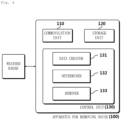
- FIG. 4 is a configuration diagram of an apparatus for removing noise for a weather radar (hereafter, an apparatus for removing noise) according to an embodiment of the present disclosure.
- the apparatus 100 for removing noise may include a communication unit 110 for communicating with a weather radar, a control unit 130 receiving an echo signal from the apparatus 100 for removing noise through the communication unit 110, and a storage unit 120 storing various kinds of information.
- the control unit 130 may perform a general control function of the apparatus 100 for removing noise and may include a RAM, a ROM, a CPU, a GPU, and buses, and the RAM, the ROM, the CPU, the GPU, etc. may be connected through the buses.
- At least one of the communication unit 110 and the storage unit 120 may be included in the control unit 130 and the communication unit 110 can communicate with a weather radar through various well-known wired/wireless communication types.
- the weather radar may include a transmitter that generates a radio wave (a microwave or radar beam) to be emitted to the atmosphere, an antenna that receives a radio wave that is emitted to the atmosphere and reflected by a target, and a receiver that amplifies and transmits the radio wave, which is reflected by the target and received through the antenna, as an echo signal to the apparatus 100 for removing noise, and may further include a radome for protecting the antenna, a waveguide through which a transmission radio and a reception radio wave move, etc.
- a radio wave a microwave or radar beam
- the echo signal may mean a signal generated by the receiver on the basis of a reception radio wave and the target may include various weather elements such as cloud, rain, snow, and hail.
- An echo signal generated by the weather radar on the basis of a radio wave reflected by a target related to weather such as precipitation is shown as an echo, such as a precipitation echo, in observation information created through the apparatus 100 for removing noise.
- An echo included in observation information described in the present disclosure may mean data created by processing the echo signal in the control unit 130, and the observation information may be a radarscope image including a plurality of preset grids including the echo.
- the radarscope image may mean an image that is displayed on a physical radarscope or an image including a virtual radarscope.
- the echo signal may include information, such as the location (coordinates) of a target that corresponds to the echo signal, an azimuth angle corresponding to the target, an altitude angle corresponding to the target, a reflectivity measured to correspond to the target, a differential reflectivity measured to correspond to the target, and a radar velocity measured to correspond to the target, and the echo signal generated on the basis of the echo signal may also include the same information as the echo signal.
- the echo may include various echoes such as a precipitation echo (or weather echo) and a non-precipitation echo (or non-weather echo).
- a precipitation echo or weather echo
- a non-precipitation echo or non-weather echo
- radio interference may be generated between an external radio wave and a reflective wave received when an external radio wave that is not a radio wave transmitted from a weather radar is received to the weather radar and the radio wave transmitted from the weather radar is reflected by a target; and the weather radar generates a signal generated by radio interference also as an echo signal.
- An echo signal generated by such radio interference is included in observation information as a radio interference echo and the radio interference echo, as described above, makes it difficult to observe a precipitation echo related to weather.
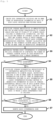
- FIG. 5 is an operation flowchart of the apparatus 100 for removing noise according to an embodiment of the present disclosure.
- control unit 130 performs a general control function of the apparatus 100 for removing noise shown in FIG. 4 .
- control unit 130 may include a data creator 131, a determiner 132, and a remover 133.
- the data creator 131 can receive an echo signal from the weather radar through the communication unit 110 and can create data information including one or more items of observation information including an echo corresponding to the echo signal on the basis of the echo signal received from the weather radar (S1).
- the data creator 131 can create the echo signal as an echo that is a radarscope or a datum displayed in a radarscope-related image, and can create one or more items of observation information including a plurality of echoes respectively corresponding to a plurality of echo signals received from the weather radar through the communication unit 110.
- the data creator 131 can create data information including the one or more items of observation information to correspond to a specific time or specific hours on the basis of one or more echo signals received at the specific time or the specific hours.
- the data information may include one or more items of observation information corresponding to one or more altitude angles, respectively, or may include one item of observation information composed of volume information for all altitude angles.
- the data creator 131 can create observation information corresponding to a single altitude angle for each of a plurality of different altitude angles on the basis of a plurality of echo signals that is received through the communication unit 110, and can create data information including a plurality of items of observation information created to correspond to the plurality of altitude angles, respectively.
- the data creator 131 can create observation information composed of volume information, in which an echo signal (or an echo) for each of a plurality of different altitude angles is included in one item of observation information, on the basis of a plurality of echo signals received through the communication unit 110, and can create data information including the observation information.
- the determiner 132 can receive data information from the data creator 131.
- the determiner 132 calculates an average reflectivity of reflectivities for one or more echoes corresponding to azimuth angles for each azimuth angle (each altitude angle) at which one or more echoes exist of a plurality of azimuth angles included in the observation information, and then calculates the number of interest azimuth angles at which the average reflectivity satisfies a preset radio interference discrimination condition, thereby being able to calculate the number of the interest azimuth angles for each of one or more items of observation information.
- the determiner 132 can calculate the average reflectivity Z H ⁇ ⁇ ⁇ in accordance with the following Equation 1.
- Z H r ⁇ ⁇ ⁇ r r ⁇ ⁇ r max ⁇ r 2.5 km r max r r ⁇ ⁇ r max
- Z H may be a reflectivity (reflectivity of an echo)
- r may be an observation radius
- r max may be a maximum observation radius
- ⁇ may be an azimuth angle
- ⁇ may be an altitude angle.
- the observation radius and the maximum observation radius may mean radii based on the center of the observation information.
- the determiner 132 can calculate the number of radio interference azimuth angles having an intense reflectivity (the number of interest azimuth angles) by calculating an average reflectivity within each azimuth angle at all altitude angles as a characteristic variable to determine whether abnormal radio interference is generated.
- a weight value is applied to the observation radius r (or the observation distance) by reflecting the characteristic that the reflectivity of a radio interference echo slightly decreases at a short distance, as in Equation 1, and since a high reflectivity may be observed from a topographical echo, a reflectivity CZ employing a topological filter is used to exclude a high reflectivity. It is preferable to exclude data within 2.5km in which the quality of data is low.
- the determiner 132 can recognize the interest azimuth angle using the preset radio interference discrimination condition, which is described in detail.
- the determiner 132 can determine whether Z H ALL ⁇ ⁇ ⁇ that is the average reflectivity calculated from Equation 1 satisfies a first condition (the following Equation 2) according to a preset radio interference discrimination condition for all regions corresponding to a specific azimuth angle for the specific azimuth angle in observation information.
- the determiner 132 can determine whether Z H NoV , ⁇ ⁇ ⁇ that is the average reflectivity calculated from Equation 1 satisfies a second condition (the following Equation 3) according to a preset radio interference discrimination condition for a region in which a radar velocity does not exist of regions corresponding to the specific azimuth angle in the observation information.
- the determiner 132 can recognize a region (or one or more regions) in which a radar velocity does not exist of regions corresponding to the specific azimuth angle in the observation information on the basis of one or more echoes corresponding to the specific azimuth angle.
- the determiner 132 can determine the specific azimuth angle as an interest azimuth angle in which a radio interference echo that is an echo generated by radio interference (radio interference echo corresponding to an echo signal generated by radio interference) exists.
- the determiner 132 can recognize azimuth angles corresponding to an interest azimuth angle of a plurality of azimuth angles included in the observation angle by determining whether the plurality of azimuth angles is an interest azimuth angle in the same way of determining whether the specific azimuth angle is an interest azimuth angle on the basis of the radio interference discrimination condition described above.
- two kinds of average reflectivities Z H ALL ⁇ ⁇ ⁇ and Z H NoV , ⁇ ⁇ ⁇ are calculated in accordance with a data use condition when calculating an average reflectivity at every azimuth angle, and the first condition and the second condition are applied to each of the average reflectivities, whereby when even one condition corresponds, it is determined as an interest azimuth angle that is a radio interference azimuth angle.
- an azimuth-angle average reflectivity over 60dBz may be observed even though a topological echo or a strong convective precipitation echo is observed, but a strong (high-reflectivity) topological echo is not shown at all azimuth angles and a reflectivity CZ employing a topological filter is used in the present disclosure, thereby excluding influence by a topological echo.
- a convective precipitation echo may be misjudged as a radio interference echo because it may be shown with a high reflectivity throughout an azimuth angle, but the present disclosure, for considering this case, applies a critical value (>60dBZ) greatly larger than an azimuth-angle average reflectivity that can be observed from precipitation to an average reflectivity Z H ALL ⁇ ⁇ ⁇ using the entire region of an azimuth angle.
- a very high reflectivity may be observed throughout one azimuth angle even from linear strong convective precipitation.
- the radio interference discrimination condition described above can be applied to radar data in which a radar observation radius is 200km or more (or an observation altitude angle is 3.5°or more) in consideration of the space scale of a convective precipitation system, and the critical value of each condition was calculated by reflecting an average reflective value that cannot be obtained from a precipitation echo.
- an intended average value characteristic from a characteristic variable Z H ⁇ ⁇ ⁇ may be distorted (a radio interference echo has a high value in the entire section), an appropriate upper limit value (e.g., Z H ALL ⁇ ⁇ ⁇ is 62.5dBZ, Z H NoV , ⁇ ⁇ ⁇ is 52.5dBZ) was applied when averaging a reflectivity so that misjudgment is not generated due to contamination of the characteristic variable.
- an appropriate upper limit value e.g., Z H ALL ⁇ ⁇ ⁇ is 62.5dBZ, Z H NoV , ⁇ ⁇ ⁇ is 52.5dBZ
- the determiner 132 can determine whether radio interference is generated for the data information by comparing the number of interest azimuth angles of each of one or more items of observation information with a preset reference for determining whether radio interference is generated (S3).
- the determiner 132 can determine that radio interference was generated in the data information when the data information includes one or more items of observation information corresponding to one or more altitude angles, respectively, and the number of the interest azimuth angles included in at least one of the one or more items of observation information exceeds 3.
- the determiner 132 can determine that radio interference was generated in the data information when the data information includes one item of observation information that is the volume information and the number of interest azimuth angles included in the observation information exceeds 5.
- Weather radar observation generally observes one plane with intervals of 1° throughout a 360° direction and performs observation for several altitude angles, thereby collecting data about 3D atmosphere in a polar coordination type.
- a weather radar performs volume observation for nine altitude angles with intervals of 5 minutes and the apparatus 100 for removing noise can process observation information in the unit of each altitude angle (single altitude angle plan data) or can process observation information and one volume datum for all altitude angles. Accordingly, in the present disclosure, when a strong radio interference direction in which the number of interest azimuth angles exceeds 3 in observation information corresponding to a single altitude angle or the number of interest azimuth angles of all azimuth angles exceeds 5 in observation information that is a volume datum is detected, data information of the corresponding time can be defined to be determined as data in which a radio interference echo was generated.
- the determiner 132 can process the specific data information as information in which a radio interference echo is not generated.
- the remover 133 in cooperation with the determiner 132, calculates an average differential reflectivity of one or more differential reflectivities of echoes corresponding to azimuth angles, respectively, included in one or more items of observation information for each of the items of observation information included in the data information, sets a radio interference-possible section in the observation information on the basis of the average differential reflectivity of each azimuth angle, and applies a preset critical condition to a plurality of grids included in the radio interference-possible section, thereby being able to recognize grids in which a radio interference echo, which is an echo generated by radio interference, is included (S5).
- the remover 133 can perform a function of removing the radio interference echo included in a grid for each of grids recognized as including the radio interference echo (S6, S7).
- the observation information may include a plurality of grids that is discriminated by an observation radius, an altitude angle, and an azimuth angle.
- the remover 133 can calculate Z DR ⁇ ⁇ ⁇ that is an average reflectivity for each azimuth angle from the observation information in accordance with the following Equation 4.
- Z DR ⁇ ⁇ ⁇ ⁇ r r + 10 km Z DR r ⁇ ⁇ n
- r may be an observation angle
- ⁇ may be an azimuth angle
- ⁇ may be an altitude angle
- n may be the number of grids that are used to calculate the average differential reflectivity from the observation information.
- the remover 133 can set, for each of azimuth angles included in the observation information, a section from an observation radius r, at which the average differential reflectivity of the azimuth angles is calculated as 75% of a value designated in advance as a precipitation range, to a maximum observation radius r max of the observation information corresponding to the azimuth angles, as a radio interference-possible section corresponding to the azimuth angles.
- the remover 133 can calculate an observation radius at which the average differential reflectivity is 75% of a value designated in advance as a precipitation range through Equation 4 for each one or more azimuth angles included in the observation information, and can set the section between the calculated observation radius and the maximum observation radius.
- the remover 133 can set one or more radio interference-possible section corresponding to the one or more azimuth angles, respectively, in the observation information.
- the value designated in advance as a precipitation range may be set as any one of values less than 5dB.
- the remover 133 recognizes grids, which satisfy the following Equation 5 according to the critical condition or satisfy the following Equation 6 according to the critical condition for each of a plurality of grids included in one or more radio interference-possible sections corresponding to one or more azimuth angles, respectively, for the radio interference-possible sections, and determines that the radio interference echo is included in the recognized grids, thereby being able to remove the radio interference echo from the recognized grids.
- Vr null or Vr > 50.0 m / s
- Z DR may be a differential reflectivity of an echo included in a grid and V r may be a radar velocity of an echo included in a grid.
- the remover 133 can remove the radio interference by applying an additional discrimination condition to each of radar observation grids (r, ⁇ , ⁇ ).
- the precipitation echo may be misjudged and removed when the critical condition is applied. Accordingly, it is possible to determine a radio interference-possible section of every azimuth angle (the dotted line (or dashed line) ⁇ end r max of the observation radius in the differential reflectivity image of FIG. 7 ), using the characteristic of a radio interference echo, in which a differential reflectivity observation value has a large positive (+) or negative (-) value in comparison to a precipitation region, and to operate the remover 133 only for the corresponding section in the way of applying the critical condition.
- the dotted line or dashed line
- the precipitation echo edge point (distance) should be flexibly determined at each azimuth angle, and the remover 133 calculates an azimuth-angle average differential reflectivity value for a distance section of 10km, as in Equation 4, and defines the section from a point (distance r), at which the value corresponds to 75% of a precipitation range ( ⁇ 5dB), to r max as a radio interference-possible section.
- the remover 133 determines whether each radar observation point (grids of observation information) is a radio interference echo and removes radio interference echoes by applying a critical condition that uses a differential reflectivity and a radar velocity as discrimination variables, after determining a radio interference-possible section.
- FIG. 8 is an example showing the result according to operations of discriminating and removing radio interference echoes of the apparatus 100 for removing noise according to an embodiment of the present disclosure, and shows the result of effectively discriminating and removing residual radio interference echoes using a characteristic variable and a discrimination condition specified for radio interference echo discrimination according to the present disclosure when applying an existing radar quality management technology optimized for the normal observation state data of FIG. 3 .
- the dynamic data processing technique of the apparatus 100 for removing noise has the advantage that it is possible to further increase the useful value of radar data by solving an unnecessary and excessive loss of precipitation echoes of normal observation and residual radio interference echoes of abnormal observation and it has a high useful value as a site support technology by improving performance of real-time radar grid-based quality management simultaneously with monitoring the observation state of a radar system.
- the present disclosure can discriminate and accurately detect an abnormal radio interference echo, which is generated in observation information created on the basis of an echo signal of a weather radar due to radio interference between an external radio wave and a reflective wave received when an external radio wave that is not a radio wave transmitted from a weather radar is received to the weather radar and the radio wave transmitted from the weather radar is reflected by a target, from a normal weather-related echo, and can give a support to be able to increase accuracy of observation information by effectively removing the abnormal radio interference echo.
- a storage 120 for example, a memory
- hardware such as a processor, a controller, an ALU (arithmetic logic unit), a digital signal processor, a microcomputer, an FPGA(Field Programmable Gate Array), a PLU (programmable logic unit), and a microprocessor; and any devices that can execute software including a set of instructions and a combination thereof or instructions and can give responses.
Landscapes
- Engineering & Computer Science (AREA)
- Radar, Positioning & Navigation (AREA)
- Remote Sensing (AREA)
- Physics & Mathematics (AREA)
- Computer Networks & Wireless Communication (AREA)
- General Physics & Mathematics (AREA)
- Electromagnetism (AREA)
- Radar Systems Or Details Thereof (AREA)
- Environmental & Geological Engineering (AREA)
- Life Sciences & Earth Sciences (AREA)
- Atmospheric Sciences (AREA)
- Biodiversity & Conservation Biology (AREA)
- Ecology (AREA)
- Environmental Sciences (AREA)
Applications Claiming Priority (1)
| Application Number | Priority Date | Filing Date | Title |
|---|---|---|---|
| KR1020210126551A KR102387059B1 (ko) | 2021-09-24 | 2021-09-24 | 기상 레이더를 위한 노이즈 제거 장치 및 방법 |
Publications (1)
| Publication Number | Publication Date |
|---|---|
| EP4155773A1 true EP4155773A1 (de) | 2023-03-29 |
Family
ID=81212085
Family Applications (1)
| Application Number | Title | Priority Date | Filing Date |
|---|---|---|---|
| EP22196602.1A Withdrawn EP4155773A1 (de) | 2021-09-24 | 2022-09-20 | Vorrichtung und verfahren zur rauschunterdrückung für ein wetterradar |
Country Status (5)
| Country | Link |
|---|---|
| US (1) | US12140668B2 (de) |
| EP (1) | EP4155773A1 (de) |
| JP (1) | JP7295317B2 (de) |
| KR (1) | KR102387059B1 (de) |
| WO (1) | WO2023048407A1 (de) |
Families Citing this family (4)
| Publication number | Priority date | Publication date | Assignee | Title |
|---|---|---|---|---|
| KR102387059B1 (ko) * | 2021-09-24 | 2022-04-15 | 대한민국 | 기상 레이더를 위한 노이즈 제거 장치 및 방법 |
| CN115686377B (zh) * | 2022-11-17 | 2023-06-09 | 福建省气象局 | 一种天气雷达数据格式存储及读取方法 |
| KR102714810B1 (ko) * | 2024-04-04 | 2024-10-11 | 대한민국 | X 밴드 기상레이더 자료에 대한 품질관리 장치 및 방법 |
| CN118033548B (zh) * | 2024-04-12 | 2024-06-18 | 成都远望科技有限责任公司 | 一种双发双收顶扫云雷达同频干扰识别方法及装置 |
Citations (5)
| Publication number | Priority date | Publication date | Assignee | Title |
|---|---|---|---|---|
| EP2296010A2 (de) * | 2009-09-14 | 2011-03-16 | Kabushiki Kaisha Toshiba | Radarvorrichtung mit Doppelpolarisierung und Störungseinschätzungsverfahren |
| KR101784607B1 (ko) * | 2016-05-02 | 2017-10-12 | 연세대학교 산학협력단 | 다중 레이더 시스템에서의 간섭 신호 제거 장치 및 방법 |
| KR101846294B1 (ko) | 2017-04-11 | 2018-05-18 | 대한민국 | 기상 레이더 기반 강우중심 추적방법 |
| CN110058241A (zh) * | 2019-04-09 | 2019-07-26 | 天津大学 | 用于天气雷达图像径向干扰回波消除的剪切波方法 |
| KR20210126551A (ko) | 2019-02-13 | 2021-10-20 | 미요시 유시 가부시끼가이샤 | 화장료 배합제 및 화장료, 및 그 제조 방법 |
Family Cites Families (10)
| Publication number | Priority date | Publication date | Assignee | Title |
|---|---|---|---|---|
| US5523759A (en) * | 1992-04-14 | 1996-06-04 | Honeywell Inc. | In flight doppler weather radar wind shear detection system |
| KR100922130B1 (ko) * | 2008-11-13 | 2009-10-16 | 부경대학교 산학협력단 | 도플러 기상레이더의 이차 에코 제거 방법 |
| KR101221773B1 (ko) * | 2011-05-09 | 2013-01-11 | 경북대학교 산학협력단 | 이중편파 레이더를 이용한 기상 및 비기상 에코 분류 방법 |
| JP2013238532A (ja) | 2012-05-16 | 2013-11-28 | Mitsubishi Electric Corp | レーダ装置及びレーダシステム |
| US9250317B1 (en) | 2012-12-20 | 2016-02-02 | Raytheon Canada Limited | Methods and apparatus for 3D radar data from 2D primary surveillance radar and passive adjunct radar |
| TWI662800B (zh) | 2017-01-26 | 2019-06-11 | 日商東芝股份有限公司 | 雷達裝置及電波干擾之迴避方法 |
| KR101868600B1 (ko) * | 2018-01-17 | 2018-06-18 | 엘아이지넥스원 주식회사 | 장거리 레이더를 이용하는 표적 탐지각 산출 장치와 방법 및 이 장치를 구비하는 장거리 레이더 시스템 |
| US10877150B2 (en) * | 2018-03-06 | 2020-12-29 | Honeywell International Inc. | Ice crystal detection by weather radar |
| KR102194427B1 (ko) * | 2020-06-09 | 2020-12-23 | 대한민국 | 기상 레이더의 관측 정보를 위한 노이즈 제거 장치 및 방법 |
| KR102387059B1 (ko) * | 2021-09-24 | 2022-04-15 | 대한민국 | 기상 레이더를 위한 노이즈 제거 장치 및 방법 |
-
2021
- 2021-09-24 KR KR1020210126551A patent/KR102387059B1/ko active Active
-
2022
- 2022-08-24 WO PCT/KR2022/012625 patent/WO2023048407A1/ko not_active Ceased
- 2022-09-07 US US17/939,887 patent/US12140668B2/en active Active
- 2022-09-15 JP JP2022146931A patent/JP7295317B2/ja active Active
- 2022-09-20 EP EP22196602.1A patent/EP4155773A1/de not_active Withdrawn
Patent Citations (5)
| Publication number | Priority date | Publication date | Assignee | Title |
|---|---|---|---|---|
| EP2296010A2 (de) * | 2009-09-14 | 2011-03-16 | Kabushiki Kaisha Toshiba | Radarvorrichtung mit Doppelpolarisierung und Störungseinschätzungsverfahren |
| KR101784607B1 (ko) * | 2016-05-02 | 2017-10-12 | 연세대학교 산학협력단 | 다중 레이더 시스템에서의 간섭 신호 제거 장치 및 방법 |
| KR101846294B1 (ko) | 2017-04-11 | 2018-05-18 | 대한민국 | 기상 레이더 기반 강우중심 추적방법 |
| KR20210126551A (ko) | 2019-02-13 | 2021-10-20 | 미요시 유시 가부시끼가이샤 | 화장료 배합제 및 화장료, 및 그 제조 방법 |
| CN110058241A (zh) * | 2019-04-09 | 2019-07-26 | 天津大学 | 用于天气雷达图像径向干扰回波消除的剪切波方法 |
Also Published As
| Publication number | Publication date |
|---|---|
| WO2023048407A1 (ko) | 2023-03-30 |
| JP7295317B2 (ja) | 2023-06-20 |
| JP2023047319A (ja) | 2023-04-05 |
| KR102387059B1 (ko) | 2022-04-15 |
| US20230094388A1 (en) | 2023-03-30 |
| US12140668B2 (en) | 2024-11-12 |
Similar Documents
| Publication | Publication Date | Title |
|---|---|---|
| EP4155773A1 (de) | Vorrichtung und verfahren zur rauschunterdrückung für ein wetterradar | |
| US8089391B1 (en) | Weather radar system and method using data from a lightning sensor | |
| CN109324335B (zh) | 一种基于激光雷达识别风切变的方法和系统 | |
| US11614539B2 (en) | Apparatus and method for removing noise for observation information of weather radar | |
| EP2172789A2 (de) | System und Verfahren zur Hinderniserkennung und Warnung | |
| CN113189554B (zh) | 雷达实测回波数据的处理方法、电子设备及存储介质 | |
| JPWO2017051647A1 (ja) | 降水粒子判別装置、気象レーダー装置、降水粒子判別方法、及び降水粒子判別プログラム | |
| CN115343681B (zh) | 一种针对空中目标的雷达可探测性评价方法 | |
| JP6712313B2 (ja) | 信号処理装置及びレーダ装置 | |
| Marzano et al. | Hydrometeor classification from dual-polarized weather radar: extending fuzzy logic from S-band to C-band data | |
| US20090167596A1 (en) | Method of processing a radar image | |
| EP2562558B1 (de) | Verfahren zur Lokalisierung von im Meer treibenden Zielen | |
| CN106501807A (zh) | 一种冰雹粒子识别方法及装置 | |
| CN105911546A (zh) | 一种海杂波的识别方法及装置 | |
| RU2100824C1 (ru) | Способ формирования сигналов грозовой опасности | |
| CN119001637A (zh) | 一种基于电信号处理的雷达监测方法及系统 | |
| KR102068287B1 (ko) | 브로드밴드 레이더를 이용한 해적선 탐지 시스템 및 그 방법 | |
| EP4113157B1 (de) | Eiskristalldetektion und -qualifizierung mittels vertikaler wetterzellenstruktur | |
| Wilson et al. | An estimation and verification of vessel radar-cross-sections for HF Surface Wave Radar | |
| US11650290B2 (en) | System and method of determining target's range profiles for costal surveillance radars | |
| KR102817941B1 (ko) | 국지적 기상 레이더에서의 기상 변화 탐지 방법 및 장치 | |
| JP2005114416A (ja) | 擾乱検出装置 | |
| KR102882733B1 (ko) | 해상 표적 탐지 레이다의 표적 처리 시스템 및 그 방법 | |
| Wu et al. | An Interferometric Method for Simultaneous Measurement of Radial and Tangential Wind Field Based on Digital Phased Array Radar | |
| RU2626018C1 (ru) | Способ определения эффективной площади рассеяния воздушных объектов бортовой радиолокационной станцией |
Legal Events
| Date | Code | Title | Description |
|---|---|---|---|
| PUAI | Public reference made under article 153(3) epc to a published international application that has entered the european phase |
Free format text: ORIGINAL CODE: 0009012 |
|
| STAA | Information on the status of an ep patent application or granted ep patent |
Free format text: STATUS: REQUEST FOR EXAMINATION WAS MADE |
|
| 17P | Request for examination filed |
Effective date: 20220920 |
|
| AK | Designated contracting states |
Kind code of ref document: A1 Designated state(s): AL AT BE BG CH CY CZ DE DK EE ES FI FR GB GR HR HU IE IS IT LI LT LU LV MC MK MT NL NO PL PT RO RS SE SI SK SM TR |
|
| STAA | Information on the status of an ep patent application or granted ep patent |
Free format text: STATUS: EXAMINATION IS IN PROGRESS |
|
| 17Q | First examination report despatched |
Effective date: 20240305 |
|
| STAA | Information on the status of an ep patent application or granted ep patent |
Free format text: STATUS: THE APPLICATION HAS BEEN WITHDRAWN |
|
| 18W | Application withdrawn |
Effective date: 20240628 |